US4942933A - Relating to rotary drill bits - Google Patents
Relating to rotary drill bitsDownload PDFInfo
- Publication number
- US4942933A US4942933AUS07/250,930US25093088AUS4942933AUS 4942933 AUS4942933 AUS 4942933AUS 25093088 AUS25093088 AUS 25093088AUS 4942933 AUS4942933 AUS 4942933A
- Authority
- US
- United States
- Prior art keywords
- cutter assemblies
- rotary drill
- cutter
- drill bit
- bit body
- Prior art date
- Legal status (The legal status is an assumption and is not a legal conclusion. Google has not performed a legal analysis and makes no representation as to the accuracy of the status listed.)
- Expired - Lifetime
Links
- 230000000712assemblyEffects0.000claimsabstractdescription92
- 238000000429assemblyMethods0.000claimsabstractdescription92
- 238000005520cutting processMethods0.000claimsabstractdescription53
- 230000033001locomotionEffects0.000claimsabstractdescription22
- 238000005553drillingMethods0.000claimsabstractdescription15
- 230000015572biosynthetic processEffects0.000claimsabstractdescription11
- 238000005755formation reactionMethods0.000claimsabstractdescription11
- 239000012530fluidSubstances0.000claimsabstractdescription8
- 238000004140cleaningMethods0.000claimsabstractdescription5
- 238000001816coolingMethods0.000claimsabstractdescription5
- 239000010432diamondSubstances0.000claimsdescription19
- 229910003460diamondInorganic materials0.000claimsdescription18
- 239000000463materialSubstances0.000claimsdescription12
- 238000005552hardfacingMethods0.000claimsdescription6
- 238000000034methodMethods0.000claimsdescription5
- 229910052751metalInorganic materials0.000claimsdescription3
- 239000002184metalSubstances0.000claimsdescription3
- 238000004663powder metallurgyMethods0.000claimsdescription3
- 239000007787solidSubstances0.000claimsdescription2
- 238000012856packingMethods0.000abstractdescription3
- UONOETXJSWQNOL-UHFFFAOYSA-Ntungsten carbideChemical compound[W+]#[C-]UONOETXJSWQNOL-UHFFFAOYSA-N0.000description9
- 238000005299abrasionMethods0.000description5
- 229910000831SteelInorganic materials0.000description2
- 238000004519manufacturing processMethods0.000description2
- 239000010959steelSubstances0.000description2
- 230000004323axial lengthEffects0.000description1
- 230000005540biological transmissionEffects0.000description1
- 238000005219brazingMethods0.000description1
- 238000004891communicationMethods0.000description1
- 238000010276constructionMethods0.000description1
- 230000000694effectsEffects0.000description1
- 238000003754machiningMethods0.000description1
- 238000000465mouldingMethods0.000description1
- 238000013021overheatingMethods0.000description1
- 239000002245particleSubstances0.000description1
- 238000000926separation methodMethods0.000description1
Images

Classifications
- E—FIXED CONSTRUCTIONS
- E21—EARTH OR ROCK DRILLING; MINING
- E21B—EARTH OR ROCK DRILLING; OBTAINING OIL, GAS, WATER, SOLUBLE OR MELTABLE MATERIALS OR A SLURRY OF MINERALS FROM WELLS
- E21B10/00—Drill bits
- E21B10/60—Drill bits characterised by conduits or nozzles for drilling fluids
- E21B10/602—Drill bits characterised by conduits or nozzles for drilling fluids the bit being a rotary drag type bit with blades
- E—FIXED CONSTRUCTIONS
- E21—EARTH OR ROCK DRILLING; MINING
- E21B—EARTH OR ROCK DRILLING; OBTAINING OIL, GAS, WATER, SOLUBLE OR MELTABLE MATERIALS OR A SLURRY OF MINERALS FROM WELLS
- E21B10/00—Drill bits
- E21B10/46—Drill bits characterised by wear resisting parts, e.g. diamond inserts
- E21B10/56—Button-type inserts
- E21B10/567—Button-type inserts with preformed cutting elements mounted on a distinct support, e.g. polycrystalline inserts
- E21B10/573—Button-type inserts with preformed cutting elements mounted on a distinct support, e.g. polycrystalline inserts characterised by support details, e.g. the substrate construction or the interface between the substrate and the cutting element
Definitions
- the inventionrelates to rotary drill bits for use in drilling or coring holes in subsurface formations and of the kind comprising a bit body having a shank for connection to a drill string, a plurality of cutter assemblies mounted at the surface of the bit body, and a passage in the bit body for supplying drilling fluid to the surface of the bit body for cooling and cleaning the cutter assemblies.
- each cutter assemblycomprises a mounting body which is received in a socket in the surface of the bit body, the mounting body having a cutter portion at one end thereof.
- the mounting bodymay comprise a separately formed stud generally in the form of a cylinder of constant cross section, the cutting portion being provided by a preform cutting element mounted on a plane surface at one end of the stud which is inclined to the centerline of the stud, or is at right angles thereto.
- the preform cutting elementmay be of the kind comprising a tablet, often circular or part-circular, having a thin, hard cutting layer of polycrystalline diamond bonded to a thicker, less hard backing layer, for example, of tungsten carbide.
- preform cutting elementsare also known which consist of a unitary body of thermally stable polycrystalline diamond.
- preform cutting elementinstead of the preform cutting element being mounted on a separately formed stud, it may be integrally formed with a backing layer of sufficient thickness for the backing layer itself to form the mounting body which is received in a socket in the bit body.
- the bit bodymay be machined from metal, usually steel, in which case the sockets for the cutter assemblies may conveniently be machined in the surface of the bit body.
- the bit body, or a part thereofis molded using a powder metallurgy process.
- the socketsare usually formed in the bit body during the molding process and may or may not be subject to further machining operations before the cutter assemblies are mounted on the bit body.
- the present inventionsets out to provide an arrangement whereby adjacent cutter assemblies may be packed together closely side-by-side on the bit body, while avoiding the disadvantages of the known arrangements.
- adjacent cutter assemblieshave their centerlines inclined at different angles, there may be provided an angular separation between adjacent mounting bodies which increases the further the bodies extend into the bit body. This can, therefore, permit a comparatively large distance between the inner ends of adjacent mounting bodies, to provide a substantial body of material between the inner ends of the bodies.
- the difference in inclination of adjacent mounting bodiesmay permit one or both of the bodies to extend more deeply into the bit body material than the other, and this also may allow closer packing of the cutting portions without detriment to the strength of the bit body around the cutter assemblies.
- the difference in inclination between the centerlines of said adjacent cutter assembliesis preferably greater than 30°, and more preferably greater than 35°.
- One of said two adjacent cutter assembliesmay have its centerline inclined at substantially 90° to said normal direction of forward movement, and the other of said cutter assemblies may have its centerline inclined at less than 90° to said normal direction of forward movement so as to be inclined rearwardly with respect to said direction.
- each said cutting portionhas a front cutting face, and the front cutting faces on said two adjacent cutter assemblies are inclined at substantially the same angle to said normal direction of forward movement of the cutter assemblies in use.
- At least some of said cutter assemblieseach comprise a preform tablet having a front cutting face of polycrystalline diamond material and a rear face bonded to a surface on a carrier.
- the preform tabletmay comprise a thin, hard facing layer of polycrystalline diamond material bonded to a less hard backing layer, the backing layer having a rear face bonded to said surface on the carrier.
- at least some of said cutter assembliesmay each comprise a thin, hard facing layer of polycrystalline diamond material bonded to a less hard backing layer, the diamond layer thereby constituting said cutting portion and the backing layer constituting said mounting body.
- One of said two adjacent cutter assembliesmay have said front cutting face thereof extending substantially at right angles to the centerline of the mounting body of the cutter assembly.
- alternate cutter assemblies in the rowmay have the centerlines thereof inclined at a first or a second angle respectively to the normal direction of forward movement thereof.
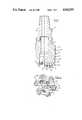
- FIG. 1is a vertical section through a rotary drill bit according to invention, the cutter assemblies being shown isometrically;
- FIG. 2is an end view of the drill bit of FIG. 1;
- FIGS. 3 and 4are lengthwise sections through adjacent cutter of the drill bit of FIGS. 1 and 2;
- FIG. 5is a sectional view of part of an alternative form of drill bit, the cutter assemblies again being shown isometrically;
- FIGS. 6 and 7are lengthwise sections through adjacent cutter assemblies of the drill bit of FIG. 5 taken on lines 6--6 and 7--7, respectively;
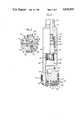
- FIG. 8is a diagrammatic vertical section through a drill bit in accordance with another embodiment of the invention.
- FIG. 9is a diagrammatic end view of the bit shown in FIG. 8.
- the bit body 10includes a separately formed shank portion 11 at one end for connection to the drill string.
- the bit body shownis molded by a powder metallurgy process, in known manner.
- the surface of the bit body 10comprises an operative end face 12 and a laterally facing portion 40.
- the operative end face 12 of the bit body 10is formed with six blades 13 radiating from the central area of the bit and the blades carry cutter assemblies 14, 15 and 16 spaced apart along the length thereof.
- the cutter assembliesare of three different types as will be described in greater detail hereafter.
- the laterally facing portion 40 of the surface of the bit bodydefines a gauge section 17 including kickers 18 which contact the walls of the borehole being drilled to stabilize the bit in the borehole.
- Laterally extending or gauge cutter assembliesare mounted at the laterally facing portion 40 of the surface of the bit body 10 below kickers 18.
- Cutter 42may be similar to cutters 14 described below, but of slightly modified shape, or of any other suitable type.
- a central passage 19 in the bit body and shankdelivers drilling fluid to nozzles 20 in the end face 12 of the bit body, in known manner.
- each blade 13there are disposed side-by-side, in a row, a number of cutter assemblies, alternate cutter assemblies in the row being indicated at 14 and 15, respectively.
- FIG. 3shows diagrammatically a cutter assembly of the type indicated at 14 in FIGS. 1 and 2.
- the cutter assemblycomprises a generally cylindrical stud 21 of circular cross section received in a correspondingly-shaped socket 22 in the bit body 10.
- the centerline of the studis indicated at 23.
- the studmay be formed from cemented tungsten carbide.
- the stud 21Adjacent its outer end, the stud 21 is formed at one side with a flat plane 24 which is inclined with respect to the centerline of the stud. Bonded onto the plane surface 24 is a cutting element 25 in the form of a circular tablet.
- the cutting elementcomprises a thin, hard facing layer 26 of polycrystalline diamond bonded to a thicker backing layer 27 of cemented tungsten carbide.
- FIG. 4illustrates the alternative type of cutter assembly 15.
- the components making up the cutter assembly 15are generally similar to the components of the assembly 14 and will not therefore be described in detail.
- the centerline 30 of each cutter assembly 15is inclined at less than 90° to the normal forward direction 29 of movement of the cutter assembly in use, for example, is inclined at 45° to such direction.
- the plane surface 31 of the stud 32 on which the cutting element 33 is mountedis inclined at such an angle to the centerline 30 of the stud that the front cutting face of the polycrystalline diamond layer 34 of the cutting element is inclined at the same angle to the formation 28 as the front cutting face of the cutting element 25 of the cutter assembly 14.
- the cutter assemblies 16 shown in FIG. 2are disposed rearwardly of the cutter assemblies 14 and 15 with respect to the normal direction of rotation of the bit.
- the cutter assemblies 16are back-up assemblies comprising bosses, for example, of cemented tungsten carbide, impregnated with natural diamonds. Although such back-up cutter assemblies will not normally require to be sufficiently closely spaced to require the arrangement according to the present invention, the invention includes within its scope arrangements in which two such adjacent cutters have their centerlines inclined at different angles with respect to the normal direction of forward movement.
- the cutting elements 25 and 33are two-layer preform cutting elements comprising a layer of polycrystalline diamond bonded to a backing layer of cemented tungsten carbide.
- preform cutting elementsare formed in an extremely high pressure, high temperature press and the preform elements are subsequently bonded, for example, by brazing, to the studs.
- the present inventionis not limited to the use of such preform cutting elements which are shown only by way of example.
- FIGS. 5-7show an alternative form of drill bit in which cutting elements of the type 14 shown in FIG. 3 are alternated along the blade 35 on the bit body 36 with a further type of cutter assembly 37.
- the cutter assembly 37comprises a hard facing layer 38 of polycrystalline diamond bonded to a thick tungsten carbide backing layer 39.
- the centerline 40 of the cutter assemblyis inclined at about 20° to the normal forward direction of movement 29 of the cutter assembly.
- the front cutting face of the polycrystalline diamond layer 38extends at right angles to the centerline 40 of the cutter assembly, and the angle of inclination of the centerline 40 is selected to provide an angle of inclination (known as the "back rake" angle) between the front cutting face and the normal to the formation which is essentially the same as the back rake angle of the cutter assembly 14.
- FIG. 6shows a cutter assembly 14 of the arrangement of FIG. 5 and also shows an adjacent cutter assembly 37 in dotted lines. It will be seen that, in this case, interference between the cutter assemblies 14 and 37 is avoided not only by virtue of the difference in the angles of inclination of centerlines 23 and 40 but also by limiting the axial length of the cutter assembly 37 and hence the extent to which it projects into the bit body 36.
- the cutter assembly 37may be of a known kind in which the two-layer cutting element is formed in the abovementioned high pressure, high temperature press but with the backing layer 29 being of substantially greater thickness than is the case in the cutting elements such as shown, for example, at 25 and 33 in FIGS. 3 and 4.
- the front polycrystalline diamond layer 38may be regarded as the cutting portion and the backing layer 39 onto which it is bonded in the press may be regarded as the mounting body of the cutter assembly.
- the inventionalso includes within its scope arrangements in which the two-layer structure shown at 37 is bonded to a further cylindrical tungsten carbide stud which extends coaxially with the backing layer 39 and rearwardly thereof.
- a similar cutter assemblymay be formed by bonding a thin, two-layer preform cutter of the kind shown at 25 and 33 to an equal diameter cylindrical tungsten carbide stud, the cutting element being bonded to the circular end face of the stud so as to be coaxial therewith.
- FIGS. 1 and 5are not true sections through the blades on which the cutter assemblies are mounted since, for clarity, the cutter assemblies are shown isometrically.
- the primary cutter assembliesi.e. the polycrystalline diamond layered assemblies 14, 15 and 37, as opposed to the back-up assembly 16 are arranged in rows with alternate cutting assemblies having the centerlines of their mounting bodies disposed at alternately different angles of inclination along the entire length of each row.
- the principles of the present inventioncan be used to advantage by providing such alternating angles of inclination only on a limited portion of a bit.
- FIGS. 8 and 9illustrate a way in which the present invention can be selectively applied only to certain portions of a drill bit.
- the main bit body 44comprises an outer fixed part 46 having at its upper end a reduced diameter portion 48 which is secured within the lower end of a sub-assembly 50, the upper end of which is formed with a threaded shank 52 for connection to the drill string.
- the surface of the fixed part 46is formed with two end face portions 54 and two laterally facing portions 55.
- end face portions 54there are mounted abrasion elements 56.
- the abrasion elements 56may be of any suitable form, for example, they may comprise tungsten carbide studs in which are embedded particles of natural diamond.
- the end face portions, and the abrasion elements thereon,constitute a secondary cutting structure.
- a movable central part 58 of the bitis axially slidable within a bore 60 in the part 46, interengaging splines 62 on the part 58 and in the bore 60 being provided for the transmission of torque between the two parts.
- the lower end of the movable part 58is formed with a head portion 64, the surface of which has end face 63 and laterally facing portions 65.
- blades 66which carry preform cutter assemblies 14 and 15, and the cutter assemblies 14 and 15 on its end face 63 constitute the primary cutting structure of the bit.
- Laterally extending cutter assemblies 42are carried at laterally facing portions 65 of the head 64 of the movable part 58 of the bit.
- drilling fluid under pressureis supplied through the passage 74, passage 72, passages 70 and nozzles 68 for cleaning and cooling the cutters.
- a piston assembly 76including a heavy duty seal 78 and scraper ring 80, is mounted on the upper end of the movable bit body part 58 and is slidable within a cylinder 83 integrally formed with the sub-assembly 50.
- the lower end of the cylinder 82is in communication, through low pressure link passages 84, with the annular space between the sub-assembly 50 and the walls of the bore, (normally referred to as the annulus).
- the cutter assemblies 14 and 15 mounted on the end face 63may be susceptible to overheating, and consequent damage or failure, as a result of excessive weight-on-bit and/or excessive torque and the configuration of the bit is such as automatically to compensate for such excessive loads.
- the configurationalso protects the cutters against momentary overloads due to impact, for example, as a result of the bit being dropped in the hole.
- the part 58may be so positioned normally in relation to the fixed part 46 that when the cutters 14 and 15 are in operation under normal weight-on-bit loads the abrasion elements 56 on the face portions 54 are either out of engagement with the formation or perform only a subsidiary cutting effect on the formation.
- the cutter assemblies 14 and 15are still, of necessity, subjected to a certain amount of heat and, of course, to the drilling forces.
- the radially outermost cutter assembliestake the brunt of this heat and force, and it is therefore desirable to place a relatively large number of cutter assemblies close together in this area.
- the studs or mounting bodies of these assembliesbe well supported by adequate material of the bit body therebetween.
- the first two cutter assemblies 14are identical to assemblies 14 of the preceding embodiments.
- the third cutter assembly 14ais in fact one of the assemblies 14, i.e. is identical thereto in form and inclination to the direction of motion (as viewed in a plane, such as FIG. 3, which is parallel to said direction), but has been given the more specific reference character 14a to distinguish it from others of the cutter assemblies 14.
- the fourth cutter assembly 15 in the rowis identical to cutter assemblies 15 of the first embodiment described hereinabove.
- the centerline of its mounting body or studis inclined at a different angle to the direction of motion from that of cutter assembly 14a.
- the fifth cutter assembly 14bis virtually identical to the other assemblies 14, and more specifically assembly 14a. More particularly, its inclination to the direction of motion is the same as those of the other assemblies 14, and is therefore different from that of assembly 15.
Landscapes
- Engineering & Computer Science (AREA)
- Life Sciences & Earth Sciences (AREA)
- Mining & Mineral Resources (AREA)
- Geology (AREA)
- Mechanical Engineering (AREA)
- Physics & Mathematics (AREA)
- Environmental & Geological Engineering (AREA)
- Fluid Mechanics (AREA)
- General Life Sciences & Earth Sciences (AREA)
- Geochemistry & Mineralogy (AREA)
- Chemical & Material Sciences (AREA)
- Crystallography & Structural Chemistry (AREA)
- Earth Drilling (AREA)
Abstract
Description
Claims (13)
Applications Claiming Priority (2)
| Application Number | Priority Date | Filing Date | Title |
|---|---|---|---|
| GB8810751 | 1988-05-06 | ||
| GB8810751AGB2218131B (en) | 1988-05-06 | 1988-05-06 | Improvements in or relating to rotary drill bits |
Related Parent Applications (1)
| Application Number | Title | Priority Date | Filing Date |
|---|---|---|---|
| US07129943Continuation-In-Part | 1987-11-25 |
Publications (1)
| Publication Number | Publication Date |
|---|---|
| US4942933Atrue US4942933A (en) | 1990-07-24 |
Family
ID=10636462
Family Applications (1)
| Application Number | Title | Priority Date | Filing Date |
|---|---|---|---|
| US07/250,930Expired - LifetimeUS4942933A (en) | 1988-05-06 | 1988-09-29 | Relating to rotary drill bits |
Country Status (2)
| Country | Link |
|---|---|
| US (1) | US4942933A (en) |
| GB (1) | GB2218131B (en) |
Cited By (30)
| Publication number | Priority date | Publication date | Assignee | Title |
|---|---|---|---|---|
| EP0502610A1 (en)* | 1991-02-01 | 1992-09-09 | Camco Drilling Group Limited | Rotary drill bits and methods of designing such drill bits |
| US5244039A (en)* | 1991-10-31 | 1993-09-14 | Camco Drilling Group Ltd. | Rotary drill bits |
| US5383527A (en)* | 1993-09-15 | 1995-01-24 | Smith International, Inc. | Asymmetrical PDC cutter |
| US5443565A (en)* | 1994-07-11 | 1995-08-22 | Strange, Jr.; William S. | Drill bit with forward sweep cutting elements |
| US5549171A (en)* | 1994-08-10 | 1996-08-27 | Smith International, Inc. | Drill bit with performance-improving cutting structure |
| US5582261A (en)* | 1994-08-10 | 1996-12-10 | Smith International, Inc. | Drill bit having enhanced cutting structure and stabilizing features |
| US5649604A (en)* | 1994-10-15 | 1997-07-22 | Camco Drilling Group Limited | Rotary drill bits |
| US5651421A (en)* | 1994-11-01 | 1997-07-29 | Camco Drilling Group Limited | Rotary drill bits |
| US5957227A (en)* | 1996-11-20 | 1999-09-28 | Total | Blade-equipped drilling tool, incorporating secondary cutting edges and passages designed for the removal of evacuated material |
| US5992549A (en)* | 1996-10-11 | 1999-11-30 | Camco Drilling Group Limited | Cutting structures for rotary drill bits |
| US6164395A (en)* | 1996-10-11 | 2000-12-26 | Camco International (Uk) Limited | Cutting structure for rotary drill bits |
| US6202770B1 (en)* | 1996-02-15 | 2001-03-20 | Baker Hughes Incorporated | Superabrasive cutting element with enhanced durability and increased wear life and apparatus so equipped |
| US6283233B1 (en)* | 1996-12-16 | 2001-09-04 | Dresser Industries, Inc | Drilling and/or coring tool |
| US6408958B1 (en) | 2000-10-23 | 2002-06-25 | Baker Hughes Incorporated | Superabrasive cutting assemblies including cutters of varying orientations and drill bits so equipped |
| US6659199B2 (en) | 2001-08-13 | 2003-12-09 | Baker Hughes Incorporated | Bearing elements for drill bits, drill bits so equipped, and method of drilling |
| US20060048973A1 (en)* | 2004-09-09 | 2006-03-09 | Brackin Van J | Rotary drill bits including at least one substantially helically extending feature, methods of operation and design thereof |
| US20060157279A1 (en)* | 2005-01-18 | 2006-07-20 | Smith International, Inc. | Fixed-head bit with stabilizing features |
| US20060278436A1 (en)* | 1999-08-26 | 2006-12-14 | Dykstra Mark W | Drilling apparatus with reduced exposure of cutters |
| US20070151770A1 (en)* | 2005-12-14 | 2007-07-05 | Thomas Ganz | Drill bits with bearing elements for reducing exposure of cutters |
| US20100276200A1 (en)* | 2009-04-30 | 2010-11-04 | Baker Hughes Incorporated | Bearing blocks for drill bits, drill bit assemblies including bearing blocks and related methods |
| US20110079438A1 (en)* | 2009-10-05 | 2011-04-07 | Baker Hughes Incorporated | Drill bits and tools for subterranean drilling, methods of manufacturing such drill bits and tools and methods of directional and off center drilling |
| US20110100721A1 (en)* | 2007-06-14 | 2011-05-05 | Baker Hughes Incorporated | Rotary drill bits including bearing blocks |
| US20110155472A1 (en)* | 2009-12-28 | 2011-06-30 | Baker Hughes Incorporated | Earth-boring tools having differing cutting elements on a blade and related methods |
| US20110192651A1 (en)* | 2010-02-05 | 2011-08-11 | Baker Hughes Incorporated | Shaped cutting elements on drill bits and other earth-boring tools, and methods of forming same |
| US8851207B2 (en) | 2011-05-05 | 2014-10-07 | Baker Hughes Incorporated | Earth-boring tools and methods of forming such earth-boring tools |
| US9022149B2 (en) | 2010-08-06 | 2015-05-05 | Baker Hughes Incorporated | Shaped cutting elements for earth-boring tools, earth-boring tools including such cutting elements, and related methods |
| US9316058B2 (en) | 2012-02-08 | 2016-04-19 | Baker Hughes Incorporated | Drill bits and earth-boring tools including shaped cutting elements |
| US9981406B2 (en) | 2015-06-25 | 2018-05-29 | Black & Decker Inc. | Drill bit |
| US10107041B2 (en)* | 2013-09-04 | 2018-10-23 | Shear Bits, Ltd. | Drill bit having shear cutters and gouging cutters |
| US11384601B2 (en) | 2019-03-01 | 2022-07-12 | Precise Drilling Components Ltd | Hole opener for horizontal directional drilling |
Families Citing this family (1)
| Publication number | Priority date | Publication date | Assignee | Title |
|---|---|---|---|---|
| US5960896A (en)* | 1997-09-08 | 1999-10-05 | Baker Hughes Incorporated | Rotary drill bits employing optimal cutter placement based on chamfer geometry |
Citations (6)
| Publication number | Priority date | Publication date | Assignee | Title |
|---|---|---|---|---|
| US4343372A (en)* | 1980-06-23 | 1982-08-10 | Hughes Tool Company | Gage row structure of an earth boring drill bit |
| US4505342A (en)* | 1982-11-22 | 1985-03-19 | Nl Industries, Inc. | Drill bit |
| GB2151283A (en)* | 1983-12-03 | 1985-07-17 | Nl Petroleum Prod | Improvements in rotary drill bits |
| US4593777A (en)* | 1983-02-22 | 1986-06-10 | Nl Industries, Inc. | Drag bit and cutters |
| US4669556A (en)* | 1984-01-31 | 1987-06-02 | Nl Industries, Inc. | Drill bit and cutter therefor |
| US4679639A (en)* | 1983-12-03 | 1987-07-14 | Nl Petroleum Products Limited | Rotary drill bits and cutting elements for such bits |
- 1988
- 1988-05-06GBGB8810751Apatent/GB2218131B/ennot_activeExpired - Lifetime
- 1988-09-29USUS07/250,930patent/US4942933A/ennot_activeExpired - Lifetime
Patent Citations (6)
| Publication number | Priority date | Publication date | Assignee | Title |
|---|---|---|---|---|
| US4343372A (en)* | 1980-06-23 | 1982-08-10 | Hughes Tool Company | Gage row structure of an earth boring drill bit |
| US4505342A (en)* | 1982-11-22 | 1985-03-19 | Nl Industries, Inc. | Drill bit |
| US4593777A (en)* | 1983-02-22 | 1986-06-10 | Nl Industries, Inc. | Drag bit and cutters |
| GB2151283A (en)* | 1983-12-03 | 1985-07-17 | Nl Petroleum Prod | Improvements in rotary drill bits |
| US4679639A (en)* | 1983-12-03 | 1987-07-14 | Nl Petroleum Products Limited | Rotary drill bits and cutting elements for such bits |
| US4669556A (en)* | 1984-01-31 | 1987-06-02 | Nl Industries, Inc. | Drill bit and cutter therefor |
Cited By (52)
| Publication number | Priority date | Publication date | Assignee | Title |
|---|---|---|---|---|
| EP0502610A1 (en)* | 1991-02-01 | 1992-09-09 | Camco Drilling Group Limited | Rotary drill bits and methods of designing such drill bits |
| US5222566A (en)* | 1991-02-01 | 1993-06-29 | Camco Drilling Group Ltd. | Rotary drill bits and methods of designing such drill bits |
| US5244039A (en)* | 1991-10-31 | 1993-09-14 | Camco Drilling Group Ltd. | Rotary drill bits |
| US5383527A (en)* | 1993-09-15 | 1995-01-24 | Smith International, Inc. | Asymmetrical PDC cutter |
| US5443565A (en)* | 1994-07-11 | 1995-08-22 | Strange, Jr.; William S. | Drill bit with forward sweep cutting elements |
| US5582261A (en)* | 1994-08-10 | 1996-12-10 | Smith International, Inc. | Drill bit having enhanced cutting structure and stabilizing features |
| US5549171A (en)* | 1994-08-10 | 1996-08-27 | Smith International, Inc. | Drill bit with performance-improving cutting structure |
| US5649604A (en)* | 1994-10-15 | 1997-07-22 | Camco Drilling Group Limited | Rotary drill bits |
| US5651421A (en)* | 1994-11-01 | 1997-07-29 | Camco Drilling Group Limited | Rotary drill bits |
| US6202770B1 (en)* | 1996-02-15 | 2001-03-20 | Baker Hughes Incorporated | Superabrasive cutting element with enhanced durability and increased wear life and apparatus so equipped |
| US5992549A (en)* | 1996-10-11 | 1999-11-30 | Camco Drilling Group Limited | Cutting structures for rotary drill bits |
| US6164395A (en)* | 1996-10-11 | 2000-12-26 | Camco International (Uk) Limited | Cutting structure for rotary drill bits |
| US5957227A (en)* | 1996-11-20 | 1999-09-28 | Total | Blade-equipped drilling tool, incorporating secondary cutting edges and passages designed for the removal of evacuated material |
| US6283233B1 (en)* | 1996-12-16 | 2001-09-04 | Dresser Industries, Inc | Drilling and/or coring tool |
| US7814990B2 (en) | 1999-08-26 | 2010-10-19 | Baker Hughes Incorporated | Drilling apparatus with reduced exposure of cutters and methods of drilling |
| US8172008B2 (en) | 1999-08-26 | 2012-05-08 | Baker Hughes Incorporated | Drilling apparatus with reduced exposure of cutters and methods of drilling |
| US20110114392A1 (en)* | 1999-08-26 | 2011-05-19 | Baker Hughes Incorporated | Drilling apparatus with reduced exposure of cutters and methods of drilling |
| US20060278436A1 (en)* | 1999-08-26 | 2006-12-14 | Dykstra Mark W | Drilling apparatus with reduced exposure of cutters |
| US8066084B2 (en) | 1999-08-26 | 2011-11-29 | Baker Hughes Incorporated | Drilling apparatus with reduced exposure of cutters and methods of drilling |
| BE1014915A5 (en) | 2000-10-23 | 2004-06-01 | Baker Hughes Inc | Structure drilling subterranean. |
| US6408958B1 (en) | 2000-10-23 | 2002-06-25 | Baker Hughes Incorporated | Superabrasive cutting assemblies including cutters of varying orientations and drill bits so equipped |
| US6659199B2 (en) | 2001-08-13 | 2003-12-09 | Baker Hughes Incorporated | Bearing elements for drill bits, drill bits so equipped, and method of drilling |
| US20080142271A1 (en)* | 2004-09-09 | 2008-06-19 | Baker Hughes Incorporated | Methods of designing rotary drill bits including at least one substantially helically extending feature |
| US7360608B2 (en) | 2004-09-09 | 2008-04-22 | Baker Hughes Incorporated | Rotary drill bits including at least one substantially helically extending feature and methods of operation |
| US20060048973A1 (en)* | 2004-09-09 | 2006-03-09 | Brackin Van J | Rotary drill bits including at least one substantially helically extending feature, methods of operation and design thereof |
| US8011275B2 (en) | 2004-09-09 | 2011-09-06 | Baker Hughes Incorporated | Methods of designing rotary drill bits including at least one substantially helically extending feature |
| US7308957B2 (en)* | 2005-01-18 | 2007-12-18 | Smith International, Inc. | Fixed-head bit with stabilizing features |
| US20060157279A1 (en)* | 2005-01-18 | 2006-07-20 | Smith International, Inc. | Fixed-head bit with stabilizing features |
| US20070151770A1 (en)* | 2005-12-14 | 2007-07-05 | Thomas Ganz | Drill bits with bearing elements for reducing exposure of cutters |
| US8752654B2 (en) | 2005-12-14 | 2014-06-17 | Baker Hughes Incorporated | Drill bits with bearing elements for reducing exposure of cutters |
| US8448726B2 (en) | 2005-12-14 | 2013-05-28 | Baker Hughes Incorporated | Drill bits with bearing elements for reducing exposure of cutters |
| US8141665B2 (en) | 2005-12-14 | 2012-03-27 | Baker Hughes Incorporated | Drill bits with bearing elements for reducing exposure of cutters |
| US8757297B2 (en) | 2007-06-14 | 2014-06-24 | Baker Hughes Incorporated | Rotary drill bits including bearing blocks |
| US20110100721A1 (en)* | 2007-06-14 | 2011-05-05 | Baker Hughes Incorporated | Rotary drill bits including bearing blocks |
| US8459382B2 (en) | 2007-06-14 | 2013-06-11 | Baker Hughes Incorporated | Rotary drill bits including bearing blocks |
| US20100276200A1 (en)* | 2009-04-30 | 2010-11-04 | Baker Hughes Incorporated | Bearing blocks for drill bits, drill bit assemblies including bearing blocks and related methods |
| US20110079438A1 (en)* | 2009-10-05 | 2011-04-07 | Baker Hughes Incorporated | Drill bits and tools for subterranean drilling, methods of manufacturing such drill bits and tools and methods of directional and off center drilling |
| US9309723B2 (en) | 2009-10-05 | 2016-04-12 | Baker Hughes Incorporated | Drill bits and tools for subterranean drilling, methods of manufacturing such drill bits and tools and methods of directional and off center drilling |
| US9890597B2 (en) | 2009-10-05 | 2018-02-13 | Baker Hughes Incorporated | Drill bits and tools for subterranean drilling including rubbing zones and related methods |
| US20110155472A1 (en)* | 2009-12-28 | 2011-06-30 | Baker Hughes Incorporated | Earth-boring tools having differing cutting elements on a blade and related methods |
| US8505634B2 (en) | 2009-12-28 | 2013-08-13 | Baker Hughes Incorporated | Earth-boring tools having differing cutting elements on a blade and related methods |
| US8794356B2 (en) | 2010-02-05 | 2014-08-05 | Baker Hughes Incorporated | Shaped cutting elements on drill bits and other earth-boring tools, and methods of forming same |
| US20110192651A1 (en)* | 2010-02-05 | 2011-08-11 | Baker Hughes Incorporated | Shaped cutting elements on drill bits and other earth-boring tools, and methods of forming same |
| US9200483B2 (en) | 2010-06-03 | 2015-12-01 | Baker Hughes Incorporated | Earth-boring tools and methods of forming such earth-boring tools |
| US9458674B2 (en) | 2010-08-06 | 2016-10-04 | Baker Hughes Incorporated | Earth-boring tools including shaped cutting elements, and related methods |
| US9022149B2 (en) | 2010-08-06 | 2015-05-05 | Baker Hughes Incorporated | Shaped cutting elements for earth-boring tools, earth-boring tools including such cutting elements, and related methods |
| US8851207B2 (en) | 2011-05-05 | 2014-10-07 | Baker Hughes Incorporated | Earth-boring tools and methods of forming such earth-boring tools |
| US9316058B2 (en) | 2012-02-08 | 2016-04-19 | Baker Hughes Incorporated | Drill bits and earth-boring tools including shaped cutting elements |
| US10017998B2 (en) | 2012-02-08 | 2018-07-10 | Baker Hughes Incorporated | Drill bits and earth-boring tools including shaped cutting elements and associated methods |
| US10107041B2 (en)* | 2013-09-04 | 2018-10-23 | Shear Bits, Ltd. | Drill bit having shear cutters and gouging cutters |
| US9981406B2 (en) | 2015-06-25 | 2018-05-29 | Black & Decker Inc. | Drill bit |
| US11384601B2 (en) | 2019-03-01 | 2022-07-12 | Precise Drilling Components Ltd | Hole opener for horizontal directional drilling |
Also Published As
| Publication number | Publication date |
|---|---|
| GB2218131B (en) | 1992-03-25 |
| GB2218131A (en) | 1989-11-08 |
| GB8810751D0 (en) | 1988-06-08 |
Similar Documents
| Publication | Publication Date | Title |
|---|---|---|
| US4942933A (en) | Relating to rotary drill bits | |
| EP0239178B1 (en) | Rotary drill bit | |
| EP0688937B1 (en) | Improvements in or relating to elements faced with superhard material | |
| EP0828917B1 (en) | Predominantly diamond cutting structures for earth boring | |
| US6269894B1 (en) | Cutting elements for rotary drill bits | |
| US6672406B2 (en) | Multi-aggressiveness cuttting face on PDC cutters and method of drilling subterranean formations | |
| US7000715B2 (en) | Rotary drill bits exhibiting cutting element placement for optimizing bit torque and cutter life | |
| US6123161A (en) | Rotary drill bits | |
| US8783388B1 (en) | Superabrasive inserts including an arcuate peripheral surface | |
| US5163524A (en) | Rotary drill bits | |
| US6230828B1 (en) | Rotary drilling bits for directional drilling exhibiting variable weight-on-bit dependent cutting characteristics | |
| EP0601840B1 (en) | Improvements in or relating to cutting elements for rotary drill bits | |
| US5816346A (en) | Rotary drill bits and methods of designing such drill bits | |
| EP0225101A2 (en) | Improvements in or relating to drill bits | |
| EP0154422B1 (en) | Improvements in rotary drill bits | |
| GB2188354A (en) | Rotary drill bit | |
| US4928777A (en) | Cutting elements for rotary drill bits | |
| US4705122A (en) | Cutter assemblies for rotary drill bits | |
| EP0962621B1 (en) | Preform cutting elements for rotary drill bits | |
| US5174396A (en) | Cutter assemblies for rotary drill bits | |
| EP0936012A1 (en) | Elements faced with superhard material |
Legal Events
| Date | Code | Title | Description |
|---|---|---|---|
| AS | Assignment | Owner name:REED TOOL COMPANY LIMITED, FARBURN INDUSTRIAL ESTA Free format text:ASSIGNMENT OF ASSIGNORS INTEREST.;ASSIGNORS:BARR, JOHN D.;WARDLEY, MICHAEL T.;REEL/FRAME:004965/0608;SIGNING DATES FROM 19881006 TO 19881028 Owner name:REED TOOL COMPANY LIMITED, SCOTLAND Free format text:ASSIGNMENT OF ASSIGNORS INTEREST;ASSIGNORS:BARR, JOHN D.;WARDLEY, MICHAEL T.;SIGNING DATES FROM 19881006 TO 19881028;REEL/FRAME:004965/0608 | |
| STCF | Information on status: patent grant | Free format text:PATENTED CASE | |
| CC | Certificate of correction | ||
| FPAY | Fee payment | Year of fee payment:4 | |
| FPAY | Fee payment | Year of fee payment:8 | |
| FPAY | Fee payment | Year of fee payment:12 | |
| AS | Assignment | Owner name:CAMCO DRILLING GROUP LIMITED, UNITED KINGDOM Free format text:CHANGE OF NAME;ASSIGNOR:REED TOOL COMPANY LIMITED;REEL/FRAME:015293/0380 Effective date:19910403 | |
| AS | Assignment | Owner name:REEDHYCALOG UK LIMITED, UNITED KINGDOM Free format text:ASSIGNMENT OF ASSIGNORS INTEREST;ASSIGNOR:CAMCO DRILLING GROUP LIMITED;REEL/FRAME:015370/0384 Effective date:20041011 |