US4942788A - Method of manufacturing a cutter for atherectomy device - Google Patents
Method of manufacturing a cutter for atherectomy deviceDownload PDFInfo
- Publication number
- US4942788A US4942788AUS07/386,905US38690589AUS4942788AUS 4942788 AUS4942788 AUS 4942788AUS 38690589 AUS38690589 AUS 38690589AUS 4942788 AUS4942788 AUS 4942788A
- Authority
- US
- United States
- Prior art keywords
- cutter
- lumen
- blank
- recited
- obstructive tissue
- Prior art date
- Legal status (The legal status is an assumption and is not a legal conclusion. Google has not performed a legal analysis and makes no representation as to the accuracy of the status listed.)
- Expired - Lifetime
Links
- 238000004519manufacturing processMethods0.000titleclaimsdescription18
- 230000000414obstructive effectEffects0.000claimsabstractdescription40
- 238000005520cutting processMethods0.000claimsabstractdescription17
- 230000000750progressive effectEffects0.000claimsabstractdescription7
- 230000000149penetrating effectEffects0.000claimsabstractdescription3
- 238000000034methodMethods0.000claimsdescription32
- 239000003082abrasive agentSubstances0.000claimsdescription2
- 230000002093peripheral effectEffects0.000claimsdescription2
- 239000012634fragmentSubstances0.000abstractdescription8
- 230000035515penetrationEffects0.000abstractdescription6
- 210000001367arteryAnatomy0.000description31
- 239000000463materialSubstances0.000description8
- 239000011159matrix materialSubstances0.000description7
- JOYRKODLDBILNP-UHFFFAOYSA-NEthyl urethaneChemical compoundCCOC(N)=OJOYRKODLDBILNP-UHFFFAOYSA-N0.000description4
- 241000282414Homo sapiensSpecies0.000description4
- 239000004952PolyamideSubstances0.000description4
- 238000009825accumulationMethods0.000description4
- 239000008280bloodSubstances0.000description4
- 210000004369bloodAnatomy0.000description4
- 229920002647polyamidePolymers0.000description4
- 239000007787solidSubstances0.000description4
- 208000027418Wounds and injuryDiseases0.000description3
- 239000000203mixtureSubstances0.000description3
- 238000007493shaping processMethods0.000description3
- 238000004804windingMethods0.000description3
- 206010002091AnaesthesiaDiseases0.000description2
- 239000004593EpoxySubstances0.000description2
- 206010020772HypertensionDiseases0.000description2
- 230000037005anaesthesiaEffects0.000description2
- 230000000903blocking effectEffects0.000description2
- 238000010276constructionMethods0.000description2
- 238000004132cross linkingMethods0.000description2
- 229920000642polymerPolymers0.000description2
- 230000009295sperm incapacitationEffects0.000description2
- 229910001220stainless steelInorganic materials0.000description2
- 239000010935stainless steelSubstances0.000description2
- 238000001356surgical procedureMethods0.000description2
- WFKWXMTUELFFGS-UHFFFAOYSA-NtungstenChemical compound[W]WFKWXMTUELFFGS-UHFFFAOYSA-N0.000description2
- 239000010937tungstenSubstances0.000description2
- 229910052721tungstenInorganic materials0.000description2
- ZOXJGFHDIHLPTG-UHFFFAOYSA-NBoronChemical compound[B]ZOXJGFHDIHLPTG-UHFFFAOYSA-N0.000description1
- 229920000049Carbon (fiber)Polymers0.000description1
- RTAQQCXQSZGOHL-UHFFFAOYSA-NTitaniumChemical compound[Ti]RTAQQCXQSZGOHL-UHFFFAOYSA-N0.000description1
- 230000009286beneficial effectEffects0.000description1
- 230000005540biological transmissionEffects0.000description1
- 229910052796boronInorganic materials0.000description1
- 239000004917carbon fiberSubstances0.000description1
- 230000015556catabolic processEffects0.000description1
- 238000000576coating methodMethods0.000description1
- 239000002131composite materialSubstances0.000description1
- 210000004351coronary vesselAnatomy0.000description1
- 230000008878couplingEffects0.000description1
- 238000010168coupling processMethods0.000description1
- 238000005859coupling reactionMethods0.000description1
- 230000003247decreasing effectEffects0.000description1
- 238000006731degradation reactionMethods0.000description1
- 229910003460diamondInorganic materials0.000description1
- 239000010432diamondSubstances0.000description1
- 239000000428dustSubstances0.000description1
- 230000000694effectsEffects0.000description1
- 238000009760electrical discharge machiningMethods0.000description1
- 238000013467fragmentationMethods0.000description1
- 238000006062fragmentation reactionMethods0.000description1
- 239000011521glassSubstances0.000description1
- 210000004013groinAnatomy0.000description1
- 208000014674injuryDiseases0.000description1
- 238000003780insertionMethods0.000description1
- 230000037431insertionEffects0.000description1
- 210000003734kidneyAnatomy0.000description1
- 238000011542limb amputationMethods0.000description1
- 208000010125myocardial infarctionDiseases0.000description1
- 210000000056organAnatomy0.000description1
- 239000002245particleSubstances0.000description1
- 230000005855radiationEffects0.000description1
- 230000003252repetitive effectEffects0.000description1
- 230000000717retained effectEffects0.000description1
- 239000000523sampleSubstances0.000description1
- 239000010936titaniumSubstances0.000description1
- 229910052719titaniumInorganic materials0.000description1
- 230000008733traumaEffects0.000description1
- UONOETXJSWQNOL-UHFFFAOYSA-Ntungsten carbideChemical compound[W+]#[C-]UONOETXJSWQNOL-UHFFFAOYSA-N0.000description1
Images


Classifications
- A—HUMAN NECESSITIES
- A61—MEDICAL OR VETERINARY SCIENCE; HYGIENE
- A61B—DIAGNOSIS; SURGERY; IDENTIFICATION
- A61B17/00—Surgical instruments, devices or methods
- A61B17/32—Surgical cutting instruments
- A61B17/3205—Excision instruments
- A61B17/3207—Atherectomy devices working by cutting or abrading; Similar devices specially adapted for non-vascular obstructions
- A61B17/320758—Atherectomy devices working by cutting or abrading; Similar devices specially adapted for non-vascular obstructions with a rotating cutting instrument, e.g. motor driven
Definitions
- This inventionrelates to apparatus for excising obstructive tissue in lumens of living beings.
- the inventionalso relates to a cutter for inclusion in such apparatus for excising such obstructive tissue from such lumens even when such obstructive tissue is hard and/or diffuse.
- the inventionalso relates to methods of forming the cutter and further relates to methods of removing obstructive tissue from the lumen of living beings.
- Heart attacksconstitute one of the major sources of incapacitation and/or death to human beings. Such failures have often resulted from blockages in coronary arteries. Such blockages have resulted from the accumulation of plaque in the arterial walls. Such accumulation of plaque has gradually blocked the flow of blood through the arteries to the heart until there is a complete stoppage or almost a complete stoppage.
- Blockage of arteries other than adjacent to the heartcan also cause incapacitation and/or death to human beings.
- plaque build-up in the arteries of the arms or legscan result in limb amputations
- plaque build-up in the arteries of the head and neckcan result in strokes
- plaque build-up in the arteries of the kidneyscan result in hypertension (high blood pressure)
- plaque build-up in other peripheral (non-coronary) arteriescan result in degradation of the organs which they supply.
- Another methodhas also been developed in recent years to alleviate the blockage of arteries in living beings.
- This methodinvolves the insertion of a balloon into the artery at a position removed from the blocked position in the artery of the living being.
- the balloonis moved as by a conduit to the blocked position in the artery.
- the balloonis then inflated to expand the diameter of the artery at the blocked position.
- By expanding the diameter of the arterythe opening in the artery at the blocked position is enlarged, thereby alleviating the blockage.
- the balloon methodhas certain inherent disadvantages. It is not desirable to expand the arterial wall at the blocked position because the expansion tends to stretch, and thereby weaken, the arterial wall. Furthermore, the plaque blocking the artery is often quite hard, fibrous, calcified and/or diffuse. This makes it difficult for the balloon to overcome the counterforce exerted by the plaque against the balloon. It has accordingly been difficult to expand the arterial wall against this counterforce. This is particularly true when the plaque is quite thick at the position where the balloon is being inflated.
- the system and method of this inventionprovide a torque tube which can be easily and efficiently inserted into the artery and manipulated to the position at which the plaque is blocking the passage of blood in the artery.
- the apparatus of this inventionalso includes a cutter which excises plaque from the arterial walls even when the plaque is hard, fibrous, calcified and/or diffuse. The apparatus then removes the plaque fragments efficiently, as by a vacuum, from the blood stream. In this way, any danger is eliminated of having the removed plaque block the artery at a position downstream from that at which the plaque is excised from the arterial wall.
- the inventionalso provides a method of forming the cutter.
- the inventionfurther provides a method of excising plaque from the arterial walls.
- a cutterpenetrates at its forward end into, and excises, obstructive tissue in a lumen in a living being by providing two spaced external segments of a cylindrical generally hollow portion with cutting surfaces at their edges.
- the cuttermay have a forward portion of restricted dimensions to facilitate the penetration of the cutter into the obstructive tissue.
- a progressively expanding portionsuch as a truncated cone extends rearwardly from the portion of restricted dimensions.
- the cutterenlarges the area of excision of the obstructive tissue from the lumen wall at progressive positions rearwardly from the forward end.
- the obstructive tissue in the lumen at the progressively expanding positionsmay be excised at the positions of penetration of the obstructive tissue by rotating the cutter manually or by a motor. The cutter may then be moved forwardly to penetrate the obstructive tissue through an additional distance in the lumen.
- the cuttermay also have a hollow portion of substantially constant dimensions, such as a hollow cylinder, at the laterally expanded end.
- This hollow cylinderis coupled to a torque tube which has strong and resilient properties to follow the contour of the lumen and to communicate a penetrating force to the forward end of the cutter and a torque to the cutter to rotate the cutter.
- a vacuummay be applied to the cutter through the torque tube to remove fragments of obstructive tissue excised from the lumen.
- a solid cylindrical rodis mounted on a lathe and the interior of the cutter is bored out along the longitudinal axis of the rod.
- the rodis then turned to dimension the outer configuration of the cutter around the interior and the resultant blank is cut from the rod.
- This blankis then held by a collet on a rectangular-shaped collet holder block.
- the collet holder, and the blank held thereon,are mounted in the V-block of an electrical discharge machine to burn holes into the blank which form the blades of the cutter. The blades are then sharpened by a lapping process.
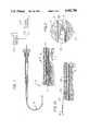
- FIG. 1is a schematic view, partially in section as to the mechanical features and partially in block form as to the electrical features, showing one embodiment of an invention for excising obstructive tissue from the lumen of a living being;
- FIG. 2is an enlarged fragmentary sectional view of a portion of the embodiment in FIG. 1, this portion being encircled by an arrow in FIG. 1 and the arrow being identified by the numeral "2";
- FIG. 3is an enlarged fragmentary view, partially broken to indicate elements in section, of a torque tube included in the embodiment shown in FIGS. 1 and 2;
- FIG. 4is an enlarged fragmentary sectional view taken substantially on the line 4--4 of FIG. 3 and illustrating certain components in the torque tube in further detail;
- FIG. 5is an enlarged perspective view of a cutter included in the embodiment shown in FIGS. 1 and 2;
- FIG. 6is an enlarged elevational view of the cutter shown in FIG. 5;
- FIG. 7is an enlarged sectional view, taken on the line 7--7 of FIG. 6, of the cutter shown in FIGS. 5 and 6 and schematically illustrates additional details of construction of the cutter;
- FIG. 8is an enlarged fragmentary sectional view taken substantially on the line 8--8 of FIG. 7 and illustrates the construction of the cutter at the front end of the cutter;
- FIG. 9is a sectional view of the cutter and is taken substantially on the line 9--9 of FIG. 8;
- FIG. 10is a view schematically illustrating how the cutter and the torque tube are advanced along a guide wire in the lumen to the position where the obstructive tissue to be excised is located;
- FIG. 11is a perspective view of the front of the cutter
- FIG. 12is a perspective view of the back of the cutter
- FIG. 13is a perspective view of an alternate embodiment of a cutter
- FIG. 14is a cross-sectional view of the cutter as seen along the line 14--14 in FIG. 13;
- FIG. 15is a perspective view of the workpiece holder assembly.
- a system generally indicated at 10for excising obstructive tissue such as plaque 12 from a lumen such as an artery 14 in a living being such as a human.
- the systemincludes a cutter generally indicated at 16, a torque tube generally indicated at 18 and a source 20 of vacuum.
- the systemmay also include a motor 22 for rotating the torque tube 18 and the cutter 16 at a relatively low speed to excise the plaque 12 from the artery 14.
- the cutter 16may be made from a suitable material such as a stainless steel.
- the cutter 16includes a hollow end portion 26 (FIGS. 5, 6 and 7) having a substantially constant shape such as a cylinder.
- the external diameter of the cylindrical portion 26may be approximately seventy-two thousandths of an inch (0.072").
- the thickness of the portion 26may be approximately four thousandths of an inch (0.004").
- the length of the portion 26may be approximately one tenth of an inch (0.1").
- An intermediate portion 28 of progressively decreasing dimensionsextends from the end portion 26.
- the intermediate portion 28may have an external length of approximately five hundredths of an inch (0.05") and may constitute a segment of a truncated cone.
- the diameter of the intermediate portion 28 at the thin or truncated end of the segmented conemay be approximately twenty-two thousandths of an inch (0.022"). As will be appreciated, these dimensions are also only illustrative.
- the intermediate portion 28is substantially hollow as indicated at 30 in FIGS. 5 and 7.
- the intermediate portion 28has a pair of diametrically disposed blades 32 defined by cutting edges 34 (FIG. 9).
- the cutting edges 34are preferably quite sharp.
- the sharpness of the cutting edges 34is enhanced by a progressive tapering (as indicated at 36), at the lateral ends of the blades 32, of the distance between the external and internal walls defining the thickness of the blades.
- the maximum thickness of each of the blades 32may be on the order of two thousandths to three thousandths of an inch (0.002"-0.003").
- Each of the blades 32preferably has external and internal surfaces with annular configurations.
- the external and internal sufaces of the blades 32may extend annularly for an angle of approximately fifty degrees (50°) or sixty degrees (60°).
- the blades 32are longer at one end than at the other end. This may be seen by comparing the blades 32 at positions 38 and 40 in FIG. 6.
- the increased length of the blades 32 at the position 38results from a cut made in the end portion 26 at a position adjacent the intermediate portion 28.
- the taper in the blades 32 at the side adjacent the position 38may be more shallow than the taper of the blades at the side adjacent the position 40.
- a tip portion 44extends from the intermediate portion 28.
- the tip portion 44has a substantially constant shape adjacent the truncated end of the intermediate portion 28.
- the tip portion 44may be cylindrical adjacent the truncated end of the intermediate portion 28.
- the external diameter of this cylindermay be approximately twenty-three thousandths of an inch (0.023").
- the diameter of this cylindermay conform substantially to the width of the blades 32 at the truncated ends of the blades.
- the opening 30 in the intermediate portion 28extends partially into the tip portion 44 as indicated at 46 in FIG. 7.
- a conical portion 48extends from the cylindrical portion of the tip portion 44.
- the diameter of the conical portion 48 at the free end of the conical portionmay be approximately sixteen thousandths of an inch (0.016").
- the conical portionis open at its forward end as indicated at 49 in FIG. 5.
- the total length of the tip portion 44may be approximately fifteen thousandths to twenty thousandths of an inch (0.015"-0.020").
- the blades 32are integrated at their forward ends by the tip portion 44. This imparts strength to the blades 32.
- the cutter 16may be initially formed with (a) a solid end portion having the external configuration of the end portion 26, (b) a solid conical portion having the external configuration of the intermediate portion 28 and (c) a tip portion having the external configuration of the tip portion 44.
- a cylindrical holemay be formed in the end portion 26 and a cylindrical hole may be formed in the tip portion 44 to form the opening 49.
- the intermediate portion 28is then burned as by electrical discharge machining to form the opening 30 (and the extended opening 46) to define the blades 32.
- cutter 16will be still further appreciated with reference to FIG. 11 and FIG. 12.
- cylinder 26establishes a base 100, and that base 100 is coaxially aligned with cylindrical-shaped tip 44. More specifically, as best described with reference to axis 102 in FIG. 12, base 100 is coaxially aligned and distanced from tip 44 along axis 102. Because the diameter of tip 44 is less than the diameter of base 100, the region intermediate tip 44 and base 100 establishes a hollow frustum 104 therebetween.
- a hole 106is cut into frustum 104 substantially as shown in FIG. 11 and a hole 108 is cut into frustum 104 diametrically opposite from hole 106 substantially as shown in FIG. 12.
- holes 106 and 108 in frustum 104create the substantially straight blades 32a and 32b which connect tip 44 with base 100.
- FIGS. 11 and 12also show that hole 108 extends longitudinally farther into base 100 than does hole 106. The result of this difference is that cutting edge 34a of blade 32a is shorter than cutting edge 34b of blade 32b.
- FIG. 12shows that blades 32a and 32b are each inclined to the axis 102 at an angle 110 which is approximately equal to forty-five degrees (45°). It will be appreciated, however, that for the purposes of the present invention angle 110 can range between approximately forty and seventy degrees (40°-70°).
- cutter 16must account for its miniaturization and the precise tolerances which are consequently required.
- a solid rod of the material to be used for cutter 16is mounted on a standard lathe (not shown).
- a drillis aligned with the longitudinal axis of the rod and advanced into the rod to bore out the interior hollow of end portion 26.
- the conically-shaped interior hollow of intermediate portion 28can be bored out along with the interior hollow of end portion 26.
- the interior hollow of intermediate portion 28can be formed in a separate operation. In either case, a cylindrically-shaped interior hollow for tip portion 44 is then formed which has an inner diameter that is substantially smaller than the inner diameter of the interior hollow of end portion 26.
- the rodis turned on the lathe in a well known manner to form the outer surfaces and establish a structure having a substantially uniform thickness.
- the resultis a blank 200 which is configured substantially as shown in FIG. 15.
- a work piece holding assemblygenerally designated 202.
- work piece holding assembly 202is to maintain blank 200 in a proper orientation during the shaping of the blades 32.
- the holding assembly 202comprises a collet 204 which has a hole 206 for receiving blank 200.
- collet 204is tapered such that when the collet 204 is pushed into the recess 208 of block 210, the jaws 212a, b and c of collet 204 close onto blank 200 and fixedly hold blank 200 in its relationship to the collet holder block 210.
- the generally rectangular block 210is effectively an extension of blank 200 which can be easily handled to orient blank 200 during the blade shaping procedure.
- collet holder block 210As a first step in the process of shaping blades 32, collet holder block 210, with blank 200 properly mounted thereon, is engaged with an electric discharge machine (not shown).
- This engagementmay be accomplished in any of several ways well known in the art such as by interlocking block 210 with a V-block 214 or between V-block 214 and a V-block 216.
- V-blocks 214 and 216are only representative of devices which will stationarily hold the combination of collet holder block 210 and blank 200.
- block 210 and blank 200can be transferred from the V-block of one machine to the V-block of another and still maintain a similar orientation with respect to the working structure.
- the blades 32 of cutter 16are formed on blank 200 by using an electric discharge machine to burn the holes 106 and 108 into frustrum 104. Since the allowable tolerances for burning holes 106 and 108 into frustrum 104 is on the order of one ten thousandths of an inch (1/10,000 in.), it will be appreciated that blank 200 must be firmly held on collet holder block 210. Further, repetitive operations require that subsequent orientations of the blank 200 be substantially identical with that of previous operations. Block 210 permits this.
- block 210is transferred to a lapping machine (not shown) where the blades 32 are lapped or filed until they have sufficiently sharp edges to perform the intended atherectomy procedure.
- the lappingmay be accomplished using a tungsten carbide lap with a diamond dust surface having particles sized on the order of one to five microns. It will be appreciated that this lapping process can be accomplished in sequential stages using progressively finer abrasives.
- cutter 16is intended to be rotated about axis 102 in the direction of arrow 112. Further, it is intended that cutter 16 be advanced, as necessary, along axis 102 in the direction of arrow 114.
- the intention here, of course,is to accomplish the operation generally shown in FIGS. 1 and 2.
- cutting edges 34a and 34bare the respective leading edges of blades 32a and 32b. As such, they cut into the obstructive tissue. It happens, however, since edge 32a is shorter than edge 32b, edge 32a makes a smaller cut into the obstructive tissue than will edge 32b. Thus, the side of cutter 16 on which blade 32a is located encounters more resistive tissue.
- cutter 16tends to deflect off axis 102 away from blade 32a and in the direction of blade 34b. As intended by the present invention, this deflection ensures that the broader sweep of blade 32b is able to cut a channel into the obstructive tissue which has a diameter that is equal to or slightly greater than the diameter of base 100. This is necessary in order for cutter 16 to advance into, rather than getting hung up on the obstructive tissue.
- hole 108extends longitudinally into base 100 to establish a heel 130.
- the length of edge 132determines the distance of heel 130 from frustum 104.
- the length of edge 132establishes the extent to which blade 32b will cut into the obstructive tissue.
- the aggressiveness of cutter 16is directly proportional to the depth of heel 130, as established by the length of edge 132. It will be appreciated by the skilled artisan that this aggressiveness, together with the deflection of cutter 16 as disclosed above, will determine the rate at which obstructive tissue is excised by cutter 16.
- guide wire 80can be passed through base 100, frustum 104 and tip 44 in a manner which will allow wire 80 to guide cutter 16 along a predetermined path.
- Means to rotate cutter 16 for its intended purposecan then be operatively attached to cutter 16.
- base 100is formed with a curved blade 116 which extends from the forward edge 118 of base 100.
- the butt 128 of blade 116may be integral with the forward edge 118 or attached thereto by any means well known in the art.
- a cutting edge 120is formed on curved blade 116 which will cut obstructive tissue during the rotation of cutter 16.
- a hole 122is formed at the end 124 of curved blade 116 and is positioned with respect to cutter 16 to intersect the longitudinal axis 126 of cutter 16. As best seen in FIG. 14, hole 122 is positioned to surroundingly receive the guide wire 80 therethrough. Also, as best seen in FIG.
- blade 116is preferably curved such that the portion of blade 116 wherein hole 122 is formed will lie in a plane that is substantially prependicular to axis 126. With this structure, curved blade 116 can be rotated about wire 80 for cutting obstructive tissue from the lumen into which guide wire 80 has been placed.
- the torque tube 18may include a thin polymeric liner 70 (FIG. 4) made from a suitable material such as a polyamide. However, polyamides or other polymeric materials may also be used for the liner 70.
- the liner 70may have a suitable thickness such as approximately five thousandths of an inch (0.005") and may have a suitable inner diameter such as approximately forty-three thousandths of an inch (0.0.43").
- a wire 72 made from a suitable material such as tungstenmay be wound spirally on the liner 70.
- Tungstenis desirable because it is strong and resilient and is able to transmit torque, particularly when spirally wound.
- the wire 72may also be made from other suitable materials such as stainless steel, titanium or polymers.
- the wire 72may have a suitable diameter such as approximately two thousandths of an inch (0.002") and a tension modulus of approximately 350 Kpsi.
- the wire 72may be wound on the liner 70 at a suitable angle such as an angle of approximately thirty degrees (30°). It will be appreciated that any resilient member with properties corresponding to those of the wire 72 may be used instead of the wire 72.
- a matrix 74is disposed on the liner 70 and the winding 72 and may be provided with a suitable thickness such as approximately three thousandths of an inch (0.003").
- the matrix 74may be made from a mixture of a urethane and an epoxy. When the mixture is cured and subjected to gamma radiation in the order of 2-3 Mrads, the matrix 74 becomes cross-linked three-dimensionally. The cross-linking binds the matrix 74 to the liner 70 and the winding 72. The cross-linking enhances the properties of the torque tube 18 in providing torque transmission and flexibility.
- the matrix 74may be made from polymeric composites using glass, boron and/or carbon fibers.
- the liner 70 and the matrix 74may be considered as a sheath encasing the wire 72.
- torque tube 18the dimensions specified above for the torque tube 18 are only illustrative. Actually, torque tubes of different sizes may be used when the cutters have different sizes. It will also be appreciated that the combination of the torque tube 18 and the cutter 16 as described above is preferred. However, other coupling members may be used with the cutter 16 than the torque tube 18. Furthermore, other cutters may be used with the torque tube 18 than the cutter 16.
- a thin resilient guide wire 80(FIG. 10) is then inserted into a lumen such as an artery 14 through the percutaneous opening and is advanced along the lumen to at least the position where the obstructive tissue such as the plaque 12 is to be excised from the lumen.
- the resilient guide wire 80is generally advanced along the lumen to a position beyond the obstruction.
- the cutter 16 and the torque tube 18are then disposed on the guide wire 80 and advanced along the guide wire to the position where the obstructive tissue is to be excised from the lumen.
- the guide wire 80may be retained in the lumen to provide a guide for the cutter 16, particularly when the cutter is to be advanced along the lumen.
- the torque tube 18may be disposed within a sleeve 76 (FIG. 1) which is disposed in the artery 14.
- the sleeve 76may be made from a suitable material such as a polyamide which may be coated with a suitable material such as a urethane. However, other polymers may be used instead of the polyamide and other coatings may be used instead of urethane.
- the sleeve 76is stationary and the torque tube 18 is rotated within the sleeve. Since the torque tube 18 is disposed within the sleeve 76, it does not rub against the artery when it is rotated.
- the torque tube 18is then operated to move the portion 44 of the cutter 16 into the plaque 12. This can be accomplished even though the plaque 12 almost completely blocks the artery and even though the plaque may be hard, fibrous, diffuse and/or calcified. This results from the force localized at the tip portion 44 and particularly from the intermediate portion 28 and the cutting edges 34 on the blades 32 in the intermediate portion. Depending upon the size of the opening remaining in the artery as a result of a partial blockage of the artery by the plaque, at least part of the intermediate portion 28 may also penetrate the plaque 12.
- the conical portion 48 of the tip 44is then forced into the plaque 12.
- the penetrationcan then be sometimes enlarged by forcing the intermediate portion 28 into the plaque. This can be accomplished because the force is concentrated substantially only at the blades 32 in the intermediate portion 28 and because the blades are relatively thin.
- the opening produced by the tip portion 44can sometimes be enlarged because the distance between the blades 32 in the intermediate portion 28 is progressively increased with progressive distances from the tip portion 44.
- the tip portion 44is advanced (and sometimes at least a portion of the intermediate portion 28) into the plaque 12, while the torque tube 18 and the cutter 16 are rotating.
- the rotationmay be accomplished manually or automatically as by the motor 22.
- the motor 22When the motor 22 is used, it may be operated at a relatively low speed such as approximately eight hundred revolutions per minute (800 rpm). By operating the motor 22 at a relatively low speed, the operator is able to control the removal of the plaque 12 from the arterial wall 14.
- the torque tube 18When the torque tube 18 is rotated either manually or by the motor 22, it transmits the torque to the cutter 16. This results from the spiral winding 72 and the cross-linked matrix 74. The resultant rotation of the cutter 16 causes the blades 32 to excise the plaque 12 from the arterial wall 14. When the plaque 12 is excised from the arterial wall 14, it enters the opening 30 between the blades 32. The plaque 12 entering the opening 30 is in a form of small fragments. The fragments of the plaque 12 are then removed through the torque tube 18 by the vacuum applied by the source 20.
- the apparatus described abovehas certain important advantages. It is able to penetrate the plaque 12, even when the plaque is hard, diffuse, fibrous and/or calcified, by concentrating the applied forces at the tip portion 44. It is then sometimes able to expand this penetration by applying the localized forces to an expanding, but thin, area in the intermediate portion 28. The apparatus then excises the plaque 12 in the penetrated area by rotating the cutter 16 to provide a fragmentation of the plaque by the blades 32.
- the application of a vacuum to the excised fragments of the plaque 12is advantageous. It insures that the fragments of the plaque 12 excised from the arterial wall are removed directly from the body of the living being. This prevents the plaque from being deposited in the lumen of an artery at a downstream position. When the fragments of the plaque 12 are removed by the source 20 from the body of the living being, relatively little blood from the living being is lost.
- the bladesare able to excise the obstructive tissue to the full external diameter of the end portion 26. This provides for an enhanced efficiency in the operation of the cutter 16.
Landscapes
- Health & Medical Sciences (AREA)
- Surgery (AREA)
- Life Sciences & Earth Sciences (AREA)
- Biomedical Technology (AREA)
- Nuclear Medicine, Radiotherapy & Molecular Imaging (AREA)
- Engineering & Computer Science (AREA)
- Vascular Medicine (AREA)
- Heart & Thoracic Surgery (AREA)
- Medical Informatics (AREA)
- Molecular Biology (AREA)
- Animal Behavior & Ethology (AREA)
- General Health & Medical Sciences (AREA)
- Public Health (AREA)
- Veterinary Medicine (AREA)
- Surgical Instruments (AREA)
Abstract
Description
Claims (14)
Priority Applications (1)
| Application Number | Priority Date | Filing Date | Title |
|---|---|---|---|
| US07/386,905US4942788A (en) | 1987-11-23 | 1989-07-26 | Method of manufacturing a cutter for atherectomy device |
Applications Claiming Priority (2)
| Application Number | Priority Date | Filing Date | Title |
|---|---|---|---|
| US07/123,713US4895166A (en) | 1987-11-23 | 1987-11-23 | Rotatable cutter for the lumen of a blood vesel |
| US07/386,905US4942788A (en) | 1987-11-23 | 1989-07-26 | Method of manufacturing a cutter for atherectomy device |
Related Parent Applications (1)
| Application Number | Title | Priority Date | Filing Date |
|---|---|---|---|
| US07/213,691Continuation-In-PartUS4887613A (en) | 1987-11-23 | 1988-06-30 | Cutter for atherectomy device |
Publications (1)
| Publication Number | Publication Date |
|---|---|
| US4942788Atrue US4942788A (en) | 1990-07-24 |
Family
ID=26821821
Family Applications (1)
| Application Number | Title | Priority Date | Filing Date |
|---|---|---|---|
| US07/386,905Expired - LifetimeUS4942788A (en) | 1987-11-23 | 1989-07-26 | Method of manufacturing a cutter for atherectomy device |
Country Status (1)
| Country | Link |
|---|---|
| US (1) | US4942788A (en) |
Cited By (38)
| Publication number | Priority date | Publication date | Assignee | Title |
|---|---|---|---|---|
| US20040143287A1 (en)* | 2003-01-21 | 2004-07-22 | Angioscore, Inc. | Apparatus and methods for treating hardened vascular lesions |
| US20050021070A1 (en)* | 2003-01-21 | 2005-01-27 | Angioscore, Inc. | Methods and apparatus for manipulating vascular prostheses |
| US20050021071A1 (en)* | 2003-01-21 | 2005-01-27 | Angioscore, Inc. | Apparatus and methods for treating hardened vascular lesions |
| US20050177130A1 (en)* | 2004-02-10 | 2005-08-11 | Angioscore, Inc. | Balloon catheter with spiral folds |
| US20060259005A1 (en)* | 2005-05-11 | 2006-11-16 | Angioscore, Inc. | Methods and systems for delivering substances into luminal walls |
| US20090105687A1 (en)* | 2007-10-05 | 2009-04-23 | Angioscore, Inc. | Scoring catheter with drug delivery membrane |
| WO2009097308A1 (en)* | 2008-01-28 | 2009-08-06 | Innovative Therapies, Inc. | Method and apparatus for manufacturing wound dressing for negative pressure wound therapy |
| US20110172658A1 (en)* | 2007-11-16 | 2011-07-14 | Kardium Inc. | Medical device for use in bodily lumens, for example an atrium |
| US8150499B2 (en)* | 2006-05-19 | 2012-04-03 | Kardium Inc. | Automatic atherectomy system |
| US8489172B2 (en) | 2008-01-25 | 2013-07-16 | Kardium Inc. | Liposuction system |
| WO2014093159A1 (en)* | 2012-12-12 | 2014-06-19 | Covidien Lp | Eccentric pass-thru cutter |
| US8920411B2 (en) | 2006-06-28 | 2014-12-30 | Kardium Inc. | Apparatus and method for intra-cardiac mapping and ablation |
| US8940002B2 (en) | 2010-09-30 | 2015-01-27 | Kardium Inc. | Tissue anchor system |
| US9011423B2 (en) | 2012-05-21 | 2015-04-21 | Kardium, Inc. | Systems and methods for selecting, activating, or selecting and activating transducers |
| US9072511B2 (en) | 2011-03-25 | 2015-07-07 | Kardium Inc. | Medical kit for constricting tissue or a bodily orifice, for example, a mitral valve |
| US9119633B2 (en) | 2006-06-28 | 2015-09-01 | Kardium Inc. | Apparatus and method for intra-cardiac mapping and ablation |
| US9173977B2 (en) | 2010-04-19 | 2015-11-03 | Angioscore, Inc. | Coating formulations for scoring or cutting balloon catheters |
| US9192468B2 (en) | 2006-06-28 | 2015-11-24 | Kardium Inc. | Method for anchoring a mitral valve |
| US9198592B2 (en) | 2012-05-21 | 2015-12-01 | Kardium Inc. | Systems and methods for activating transducers |
| US9204964B2 (en) | 2009-10-01 | 2015-12-08 | Kardium Inc. | Medical device, kit and method for constricting tissue or a bodily orifice, for example, a mitral valve |
| US9351756B2 (en) | 2010-09-21 | 2016-05-31 | Angioscore, Inc. | Method and system for treating valve stenosis |
| US9375328B2 (en) | 2001-11-09 | 2016-06-28 | Angioscore, Inc. | Balloon catheter with non-deployable stent |
| US9452016B2 (en) | 2011-01-21 | 2016-09-27 | Kardium Inc. | Catheter system |
| US9480525B2 (en) | 2011-01-21 | 2016-11-01 | Kardium, Inc. | High-density electrode-based medical device system |
| US9492227B2 (en) | 2011-01-21 | 2016-11-15 | Kardium Inc. | Enhanced medical device for use in bodily cavities, for example an atrium |
| USD777926S1 (en) | 2012-01-20 | 2017-01-31 | Kardium Inc. | Intra-cardiac procedure device |
| USD777925S1 (en) | 2012-01-20 | 2017-01-31 | Kardium Inc. | Intra-cardiac procedure device |
| US9572557B2 (en) | 2006-02-21 | 2017-02-21 | Kardium Inc. | Method and device for closing holes in tissue |
| US9744038B2 (en) | 2008-05-13 | 2017-08-29 | Kardium Inc. | Medical device for constricting tissue or a bodily orifice, for example a mitral valve |
| US10028783B2 (en) | 2006-06-28 | 2018-07-24 | Kardium Inc. | Apparatus and method for intra-cardiac mapping and ablation |
| US10086178B2 (en) | 2001-11-09 | 2018-10-02 | Angioscore, Inc. | Balloon catheter with non-deployable stent |
| US10117668B2 (en) | 2013-10-08 | 2018-11-06 | The Spectranetics Corporation | Balloon catheter with non-deployable stent having improved stability |
| US10368936B2 (en) | 2014-11-17 | 2019-08-06 | Kardium Inc. | Systems and methods for selecting, activating, or selecting and activating transducers |
| US10722184B2 (en) | 2014-11-17 | 2020-07-28 | Kardium Inc. | Systems and methods for selecting, activating, or selecting and activating transducers |
| US10827977B2 (en) | 2012-05-21 | 2020-11-10 | Kardium Inc. | Systems and methods for activating transducers |
| US11033392B2 (en) | 2006-08-02 | 2021-06-15 | Kardium Inc. | System for improving diastolic dysfunction |
| US11259867B2 (en) | 2011-01-21 | 2022-03-01 | Kardium Inc. | High-density electrode-based medical device system |
| US11389232B2 (en) | 2006-06-28 | 2022-07-19 | Kardium Inc. | Apparatus and method for intra-cardiac mapping and ablation |
Citations (32)
| Publication number | Priority date | Publication date | Assignee | Title |
|---|---|---|---|---|
| US2729210A (en)* | 1954-06-22 | 1956-01-03 | Frank C Spencer | Medical instrument |
| US2749909A (en)* | 1956-06-12 | Biopsy knife | ||
| US3512519A (en)* | 1967-10-26 | 1970-05-19 | Robert M Hall | Anatomical biopsy sampler |
| US3605721A (en)* | 1969-11-03 | 1971-09-20 | Ismet Hallac | Biopsy needle |
| US3815604A (en)* | 1972-06-19 | 1974-06-11 | Malley C O | Apparatus for intraocular surgery |
| US3990453A (en)* | 1973-04-25 | 1976-11-09 | Douvas Nicholas G | Apparatus for cataract surgery |
| US4273128A (en)* | 1980-01-14 | 1981-06-16 | Lary Banning G | Coronary cutting and dilating instrument |
| US4320762A (en)* | 1975-03-10 | 1982-03-23 | Bentov Itzhak E | Dilator |
| US4441509A (en)* | 1981-05-21 | 1984-04-10 | Sherwood Medical Company | Endometrial sampling device |
| US4589412A (en)* | 1984-01-03 | 1986-05-20 | Intravascular Surgical Instruments, Inc. | Method and apparatus for surgically removing remote deposits |
| US4598710A (en)* | 1984-01-20 | 1986-07-08 | Urban Engineering Company, Inc. | Surgical instrument and method of making same |
| US4610662A (en)* | 1981-11-24 | 1986-09-09 | Schneider Medintag Ag | Method for the elimination or the enlargement of points of constriction in vessels carrying body fluids |
| US4627436A (en)* | 1984-03-01 | 1986-12-09 | Innoventions Biomedical Inc. | Angioplasty catheter and method for use thereof |
| US4631052A (en)* | 1984-01-03 | 1986-12-23 | Intravascular Surgical Instruments, Inc. | Method and apparatus for surgically removing remote deposits |
| US4636195A (en)* | 1982-04-02 | 1987-01-13 | Harvey Wolinsky | Method and apparatus for removing arterial constriction |
| US4640296A (en)* | 1983-11-12 | 1987-02-03 | Schnepp Pesch Wolfram | Biopsy cannula |
| US4646738A (en)* | 1985-12-05 | 1987-03-03 | Concept, Inc. | Rotary surgical tool |
| US4653496A (en)* | 1985-02-01 | 1987-03-31 | Bundy Mark A | Transluminal lysing system |
| US4655217A (en)* | 1985-10-11 | 1987-04-07 | Reed Matt H | Method and apparatus for disabling vein valves in-situ |
| US4664112A (en)* | 1985-08-12 | 1987-05-12 | Intravascular Surgical Instruments, Inc. | Catheter based surgical methods and apparatus therefor |
| US4669469A (en)* | 1986-02-28 | 1987-06-02 | Devices For Vascular Intervention | Single lumen atherectomy catheter device |
| US4679557A (en)* | 1984-09-10 | 1987-07-14 | E. R. Squibb & Sons, Inc. | Electrodynamic transluminal angioplasty system |
| US4685458A (en)* | 1984-03-01 | 1987-08-11 | Vaser, Inc. | Angioplasty catheter and method for use thereof |
| US4686982A (en)* | 1985-06-19 | 1987-08-18 | John Nash | Spiral wire bearing for rotating wire drive catheter |
| US4690140A (en)* | 1986-04-01 | 1987-09-01 | John Mecca | Arterial regenerator |
| US4696667A (en)* | 1986-03-20 | 1987-09-29 | Helmut Masch | Intravascular catheter and method |
| US4708147A (en)* | 1985-02-25 | 1987-11-24 | Haaga John R | Universal biopsy needle |
| US4728319A (en)* | 1986-03-20 | 1988-03-01 | Helmut Masch | Intravascular catheter |
| US4732154A (en)* | 1984-05-14 | 1988-03-22 | Surgical Systems & Instruments, Inc. | Rotary catheter system |
| US4754755A (en)* | 1984-05-14 | 1988-07-05 | Husted Royce Hill | Catheter with a rotary blade |
| US4757826A (en)* | 1985-05-01 | 1988-07-19 | Gazi Abdulhay | Endocervical biopsy instrument |
| US4765332A (en)* | 1986-07-14 | 1988-08-23 | Medinnovations, Inc. | Pullback atherectomy catheter system |
- 1989
- 1989-07-26USUS07/386,905patent/US4942788A/ennot_activeExpired - Lifetime
Patent Citations (32)
| Publication number | Priority date | Publication date | Assignee | Title |
|---|---|---|---|---|
| US2749909A (en)* | 1956-06-12 | Biopsy knife | ||
| US2729210A (en)* | 1954-06-22 | 1956-01-03 | Frank C Spencer | Medical instrument |
| US3512519A (en)* | 1967-10-26 | 1970-05-19 | Robert M Hall | Anatomical biopsy sampler |
| US3605721A (en)* | 1969-11-03 | 1971-09-20 | Ismet Hallac | Biopsy needle |
| US3815604A (en)* | 1972-06-19 | 1974-06-11 | Malley C O | Apparatus for intraocular surgery |
| US3990453A (en)* | 1973-04-25 | 1976-11-09 | Douvas Nicholas G | Apparatus for cataract surgery |
| US4320762A (en)* | 1975-03-10 | 1982-03-23 | Bentov Itzhak E | Dilator |
| US4273128A (en)* | 1980-01-14 | 1981-06-16 | Lary Banning G | Coronary cutting and dilating instrument |
| US4441509A (en)* | 1981-05-21 | 1984-04-10 | Sherwood Medical Company | Endometrial sampling device |
| US4610662A (en)* | 1981-11-24 | 1986-09-09 | Schneider Medintag Ag | Method for the elimination or the enlargement of points of constriction in vessels carrying body fluids |
| US4636195A (en)* | 1982-04-02 | 1987-01-13 | Harvey Wolinsky | Method and apparatus for removing arterial constriction |
| US4640296A (en)* | 1983-11-12 | 1987-02-03 | Schnepp Pesch Wolfram | Biopsy cannula |
| US4589412A (en)* | 1984-01-03 | 1986-05-20 | Intravascular Surgical Instruments, Inc. | Method and apparatus for surgically removing remote deposits |
| US4631052A (en)* | 1984-01-03 | 1986-12-23 | Intravascular Surgical Instruments, Inc. | Method and apparatus for surgically removing remote deposits |
| US4598710A (en)* | 1984-01-20 | 1986-07-08 | Urban Engineering Company, Inc. | Surgical instrument and method of making same |
| US4627436A (en)* | 1984-03-01 | 1986-12-09 | Innoventions Biomedical Inc. | Angioplasty catheter and method for use thereof |
| US4685458A (en)* | 1984-03-01 | 1987-08-11 | Vaser, Inc. | Angioplasty catheter and method for use thereof |
| US4754755A (en)* | 1984-05-14 | 1988-07-05 | Husted Royce Hill | Catheter with a rotary blade |
| US4732154A (en)* | 1984-05-14 | 1988-03-22 | Surgical Systems & Instruments, Inc. | Rotary catheter system |
| US4679557A (en)* | 1984-09-10 | 1987-07-14 | E. R. Squibb & Sons, Inc. | Electrodynamic transluminal angioplasty system |
| US4653496A (en)* | 1985-02-01 | 1987-03-31 | Bundy Mark A | Transluminal lysing system |
| US4708147A (en)* | 1985-02-25 | 1987-11-24 | Haaga John R | Universal biopsy needle |
| US4757826A (en)* | 1985-05-01 | 1988-07-19 | Gazi Abdulhay | Endocervical biopsy instrument |
| US4686982A (en)* | 1985-06-19 | 1987-08-18 | John Nash | Spiral wire bearing for rotating wire drive catheter |
| US4664112A (en)* | 1985-08-12 | 1987-05-12 | Intravascular Surgical Instruments, Inc. | Catheter based surgical methods and apparatus therefor |
| US4655217A (en)* | 1985-10-11 | 1987-04-07 | Reed Matt H | Method and apparatus for disabling vein valves in-situ |
| US4646738A (en)* | 1985-12-05 | 1987-03-03 | Concept, Inc. | Rotary surgical tool |
| US4669469A (en)* | 1986-02-28 | 1987-06-02 | Devices For Vascular Intervention | Single lumen atherectomy catheter device |
| US4728319A (en)* | 1986-03-20 | 1988-03-01 | Helmut Masch | Intravascular catheter |
| US4696667A (en)* | 1986-03-20 | 1987-09-29 | Helmut Masch | Intravascular catheter and method |
| US4690140A (en)* | 1986-04-01 | 1987-09-01 | John Mecca | Arterial regenerator |
| US4765332A (en)* | 1986-07-14 | 1988-08-23 | Medinnovations, Inc. | Pullback atherectomy catheter system |
Non-Patent Citations (6)
| Title |
|---|
| Banning G. Lary, M.D., and Roger W. Sherman, M.D., A Method for Creating a Coronary Myocardial Artery, Surgery, St. Louis , Jun., 1966, vol. 59, No. 6, pp. 1061 1064.* |
| Banning G. Lary, M.D., and Roger W. Sherman, M.D., A Method for Creating a Coronary-Myocardial Artery, Surgery, St. Louis, Jun., 1966, vol. 59, No. 6, pp. 1061-1064. |
| Banning G. Lary, M.D., Coronary Artery Incision and Dilation, Archives of Surgery, Dec. 1980, vol. 115, pp. 1478 1480.* |
| Banning G. Lary, M.D., Coronary Artery Incision and Dilation, Archives of Surgery, Dec. 1980, vol. 115, pp. 1478-1480. |
| Banning G. Lary, M.D., Method for Increasing the Diameter of Long Segments of the Coronary Artery, The American Surgeon, Jan., 1966, vol. 32, No. 1, pp. 33 35.* |
| Banning G. Lary, M.D., Method for Increasing the Diameter of Long Segments of the Coronary Artery, The American Surgeon, Jan., 1966, vol. 32, No. 1, pp. 33-35. |
Cited By (137)
| Publication number | Priority date | Publication date | Assignee | Title |
|---|---|---|---|---|
| US10086178B2 (en) | 2001-11-09 | 2018-10-02 | Angioscore, Inc. | Balloon catheter with non-deployable stent |
| US11571554B2 (en) | 2001-11-09 | 2023-02-07 | Angioscore, Inc. | Balloon catheter with non-deployable stent |
| US9375328B2 (en) | 2001-11-09 | 2016-06-28 | Angioscore, Inc. | Balloon catheter with non-deployable stent |
| US9962529B2 (en) | 2003-01-21 | 2018-05-08 | Angioscore, Inc. | Apparatus and methods for treating hardened vascular lesions |
| US20050021071A1 (en)* | 2003-01-21 | 2005-01-27 | Angioscore, Inc. | Apparatus and methods for treating hardened vascular lesions |
| US8721667B2 (en) | 2003-01-21 | 2014-05-13 | Angioscore, Inc. | Apparatus and methods for treating hardened vascular lesions |
| US10722694B2 (en) | 2003-01-21 | 2020-07-28 | Angioscore, Inc. | Apparatus and methods for treating hardened vascular lesions |
| US20050021070A1 (en)* | 2003-01-21 | 2005-01-27 | Angioscore, Inc. | Methods and apparatus for manipulating vascular prostheses |
| US7686824B2 (en) | 2003-01-21 | 2010-03-30 | Angioscore, Inc. | Apparatus and methods for treating hardened vascular lesions |
| US7955350B2 (en) | 2003-01-21 | 2011-06-07 | Angioscore, Inc. | Apparatus and methods for treating hardened vascular lesions |
| US20040143287A1 (en)* | 2003-01-21 | 2004-07-22 | Angioscore, Inc. | Apparatus and methods for treating hardened vascular lesions |
| US8080026B2 (en) | 2003-01-21 | 2011-12-20 | Angioscore, Inc. | Apparatus and methods for treating hardened vascular lesions |
| US20040243158A1 (en)* | 2003-01-21 | 2004-12-02 | Angioscore, Inc., A Delaware Corporation | Apparatus and methods for treating hardened vascular lesions |
| US8454636B2 (en) | 2003-01-21 | 2013-06-04 | Angioscore, Inc. | Apparatus and methods for treating hardened vascular lesions |
| US20050177130A1 (en)* | 2004-02-10 | 2005-08-11 | Angioscore, Inc. | Balloon catheter with spiral folds |
| US8864743B2 (en) | 2005-05-11 | 2014-10-21 | Angioscore, Inc. | Methods and systems for delivering substances into luminal walls |
| US10342960B2 (en) | 2005-05-11 | 2019-07-09 | Angioscore, Inc. | Methods and systems for delivering substances into luminal walls |
| US20060259005A1 (en)* | 2005-05-11 | 2006-11-16 | Angioscore, Inc. | Methods and systems for delivering substances into luminal walls |
| US10076641B2 (en) | 2005-05-11 | 2018-09-18 | The Spectranetics Corporation | Methods and systems for delivering substances into luminal walls |
| US11420030B2 (en) | 2005-05-11 | 2022-08-23 | Angioscore, Inc. | Methods and systems for delivering substances into luminal walls |
| US9586031B2 (en) | 2005-05-11 | 2017-03-07 | Angioscore, Inc. | Methods and systems for delivering substances into luminal walls |
| US9572557B2 (en) | 2006-02-21 | 2017-02-21 | Kardium Inc. | Method and device for closing holes in tissue |
| US8150499B2 (en)* | 2006-05-19 | 2012-04-03 | Kardium Inc. | Automatic atherectomy system |
| US8532746B2 (en) | 2006-05-19 | 2013-09-10 | Kardium Inc. | Automatic atherectomy system |
| US8920411B2 (en) | 2006-06-28 | 2014-12-30 | Kardium Inc. | Apparatus and method for intra-cardiac mapping and ablation |
| US9192468B2 (en) | 2006-06-28 | 2015-11-24 | Kardium Inc. | Method for anchoring a mitral valve |
| US9987083B2 (en) | 2006-06-28 | 2018-06-05 | Kardium Inc. | Apparatus and method for intra-cardiac mapping and ablation |
| US9987084B2 (en) | 2006-06-28 | 2018-06-05 | Kardium Inc. | Apparatus and method for intra-cardiac mapping and ablation |
| US9119634B2 (en) | 2006-06-28 | 2015-09-01 | Kardium Inc. | Apparatus and method for intra-cardiac mapping and ablation |
| US9119633B2 (en) | 2006-06-28 | 2015-09-01 | Kardium Inc. | Apparatus and method for intra-cardiac mapping and ablation |
| US10820941B2 (en) | 2006-06-28 | 2020-11-03 | Kardium Inc. | Apparatus and method for intra-cardiac mapping and ablation |
| US11389231B2 (en) | 2006-06-28 | 2022-07-19 | Kardium Inc. | Apparatus and method for intra-cardiac mapping and ablation |
| US10828094B2 (en) | 2006-06-28 | 2020-11-10 | Kardium Inc. | Apparatus and method for intra-cardiac mapping and ablation |
| US10828093B2 (en) | 2006-06-28 | 2020-11-10 | Kardium Inc. | Apparatus and method for intra-cardiac mapping and ablation |
| US11399890B2 (en) | 2006-06-28 | 2022-08-02 | Kardium Inc. | Apparatus and method for intra-cardiac mapping and ablation |
| US10028783B2 (en) | 2006-06-28 | 2018-07-24 | Kardium Inc. | Apparatus and method for intra-cardiac mapping and ablation |
| US11389232B2 (en) | 2006-06-28 | 2022-07-19 | Kardium Inc. | Apparatus and method for intra-cardiac mapping and ablation |
| US11033392B2 (en) | 2006-08-02 | 2021-06-15 | Kardium Inc. | System for improving diastolic dysfunction |
| US20090105687A1 (en)* | 2007-10-05 | 2009-04-23 | Angioscore, Inc. | Scoring catheter with drug delivery membrane |
| US10828097B2 (en) | 2007-11-16 | 2020-11-10 | Kardium Inc. | Medical device for use in bodily lumens, for example an atrium |
| US10499986B2 (en) | 2007-11-16 | 2019-12-10 | Kardium Inc. | Medical device for use in bodily lumens, for example an atrium |
| US11076913B2 (en) | 2007-11-16 | 2021-08-03 | Kardium Inc. | Medical device for use in bodily lumens, for example an atrium |
| US11331141B2 (en) | 2007-11-16 | 2022-05-17 | Kardium Inc. | Medical device for use in bodily lumens, for example an atrium |
| US11801091B2 (en) | 2007-11-16 | 2023-10-31 | Kardium Inc. | Medical device for use in bodily lumens, for example an atrium |
| US20110172658A1 (en)* | 2007-11-16 | 2011-07-14 | Kardium Inc. | Medical device for use in bodily lumens, for example an atrium |
| US10828096B2 (en) | 2007-11-16 | 2020-11-10 | Kardium Inc. | Medical device for use in bodily lumens, for example an atrium |
| US8906011B2 (en) | 2007-11-16 | 2014-12-09 | Kardium Inc. | Medical device for use in bodily lumens, for example an atrium |
| US10828098B2 (en) | 2007-11-16 | 2020-11-10 | Kardium Inc. | Medical device for use in bodily lumens, for example an atrium |
| US10828095B2 (en) | 2007-11-16 | 2020-11-10 | Kardium Inc. | Medical device for use in bodily lumens, for example an atrium |
| US11413091B2 (en) | 2007-11-16 | 2022-08-16 | Kardium Inc. | Medical device for use in bodily lumens, for example an atrium |
| US8932287B2 (en) | 2007-11-16 | 2015-01-13 | Kardium Inc. | Medical device for use in bodily lumens, for example an atrium |
| US11432874B2 (en) | 2007-11-16 | 2022-09-06 | Kardium Inc. | Medical device for use in bodily lumens, for example an atrium |
| US9585717B2 (en) | 2007-11-16 | 2017-03-07 | Kardium Inc. | Medical device for use in bodily lumens, for example an atrium |
| US9603661B2 (en) | 2007-11-16 | 2017-03-28 | Kardium Inc. | Medical device for use in bodily lumens, for example an atrium |
| US11751940B2 (en) | 2007-11-16 | 2023-09-12 | Kardium Inc. | Medical device for use in bodily lumens, for example an atrium |
| US11304751B2 (en) | 2007-11-16 | 2022-04-19 | Kardium Inc. | Medical device for use in bodily lumens, for example an atrium |
| US11633231B2 (en) | 2007-11-16 | 2023-04-25 | Kardium Inc. | Medical device for use in bodily lumens, for example an atrium |
| US9750569B2 (en) | 2007-11-16 | 2017-09-05 | Kardium Inc. | Medical device for use in bodily lumens, for example an atrium |
| US9820810B2 (en) | 2007-11-16 | 2017-11-21 | Kardium Inc. | Medical device for use in bodily lumens, for example an atrium |
| US9839474B2 (en) | 2007-11-16 | 2017-12-12 | Kardium Inc. | Medical device for use in bodily lumens, for example an atrium |
| US9877779B2 (en) | 2007-11-16 | 2018-01-30 | Kardium Inc. | Medical device for use in bodily lumens, for example an atrium |
| US8489172B2 (en) | 2008-01-25 | 2013-07-16 | Kardium Inc. | Liposuction system |
| WO2009097308A1 (en)* | 2008-01-28 | 2009-08-06 | Innovative Therapies, Inc. | Method and apparatus for manufacturing wound dressing for negative pressure wound therapy |
| US20100018370A1 (en)* | 2008-01-28 | 2010-01-28 | David Tumey | Method and apparatus for manufacturing wound dressing for negative pressure wound therapy |
| US9744038B2 (en) | 2008-05-13 | 2017-08-29 | Kardium Inc. | Medical device for constricting tissue or a bodily orifice, for example a mitral valve |
| US9867703B2 (en) | 2009-10-01 | 2018-01-16 | Kardium Inc. | Medical device, kit and method for constricting tissue or a bodily orifice, for example, a mitral valve |
| US10687941B2 (en) | 2009-10-01 | 2020-06-23 | Kardium Inc. | Medical device, kit and method for constricting tissue or a bodily orifice, for example, a mitral valve |
| US10813758B2 (en) | 2009-10-01 | 2020-10-27 | Kardium Inc. | Medical device, kit and method for constricting tissue or a bodily orifice, for example, a mitral valve |
| US9204964B2 (en) | 2009-10-01 | 2015-12-08 | Kardium Inc. | Medical device, kit and method for constricting tissue or a bodily orifice, for example, a mitral valve |
| US9173977B2 (en) | 2010-04-19 | 2015-11-03 | Angioscore, Inc. | Coating formulations for scoring or cutting balloon catheters |
| US10471184B2 (en) | 2010-04-19 | 2019-11-12 | Angioscore, Inc. | Coating formulations for scoring or cutting balloon catheters |
| US10314947B2 (en) | 2010-04-19 | 2019-06-11 | Angioscore, Inc. | Coating formulations for scoring or cutting balloon catheters |
| US9351756B2 (en) | 2010-09-21 | 2016-05-31 | Angioscore, Inc. | Method and system for treating valve stenosis |
| US9364254B2 (en) | 2010-09-21 | 2016-06-14 | Angioscore, Inc. | Method and system for treating valve stenosis |
| US10736652B2 (en) | 2010-09-21 | 2020-08-11 | Angioscore, Inc. | Method and system for treating valve stenosis |
| US8940002B2 (en) | 2010-09-30 | 2015-01-27 | Kardium Inc. | Tissue anchor system |
| US10485608B2 (en) | 2011-01-21 | 2019-11-26 | Kardium Inc. | Catheter system |
| US12383325B2 (en) | 2011-01-21 | 2025-08-12 | Kardium Inc. | Enhanced medical device for use in bodily cavities, for example an atrium |
| US12059202B2 (en) | 2011-01-21 | 2024-08-13 | Kardium Inc. | Catheter system |
| US9486273B2 (en) | 2011-01-21 | 2016-11-08 | Kardium Inc. | High-density electrode-based medical device system |
| US11896295B2 (en) | 2011-01-21 | 2024-02-13 | Kardium Inc. | High-density electrode-based medical device system |
| US9492227B2 (en) | 2011-01-21 | 2016-11-15 | Kardium Inc. | Enhanced medical device for use in bodily cavities, for example an atrium |
| US11607261B2 (en) | 2011-01-21 | 2023-03-21 | Kardium Inc. | Enhanced medical device for use in bodily cavities, for example an atrium |
| US11596463B2 (en) | 2011-01-21 | 2023-03-07 | Kardium Inc. | Enhanced medical device for use in bodily cavities, for example an atrium |
| US9492228B2 (en) | 2011-01-21 | 2016-11-15 | Kardium Inc. | Enhanced medical device for use in bodily cavities, for example an atrium |
| US12349955B2 (en) | 2011-01-21 | 2025-07-08 | Kardium Inc. | Enhanced medical device for use in bodily cavities, for example an atrium |
| US11399881B2 (en) | 2011-01-21 | 2022-08-02 | Kardium Inc. | Enhanced medical device for use in bodily cavities, for example an atrium |
| US12178490B2 (en) | 2011-01-21 | 2024-12-31 | Kardium Inc. | Enhanced medical device for use in bodily cavities, for example an atrium |
| US9675401B2 (en) | 2011-01-21 | 2017-06-13 | Kardium Inc. | Enhanced medical device for use in bodily cavities, for example an atrium |
| US11350989B2 (en) | 2011-01-21 | 2022-06-07 | Kardium Inc. | Catheter system |
| US9452016B2 (en) | 2011-01-21 | 2016-09-27 | Kardium Inc. | Catheter system |
| US11298173B2 (en) | 2011-01-21 | 2022-04-12 | Kardium Inc. | Enhanced medical device for use in bodily cavities, for example an atrium |
| US11259867B2 (en) | 2011-01-21 | 2022-03-01 | Kardium Inc. | High-density electrode-based medical device system |
| US9480525B2 (en) | 2011-01-21 | 2016-11-01 | Kardium, Inc. | High-density electrode-based medical device system |
| US9526573B2 (en) | 2011-01-21 | 2016-12-27 | Kardium Inc. | Enhanced medical device for use in bodily cavities, for example an atrium |
| US9072511B2 (en) | 2011-03-25 | 2015-07-07 | Kardium Inc. | Medical kit for constricting tissue or a bodily orifice, for example, a mitral valve |
| US10058318B2 (en) | 2011-03-25 | 2018-08-28 | Kardium Inc. | Medical kit for constricting tissue or a bodily orifice, for example, a mitral valve |
| USD777925S1 (en) | 2012-01-20 | 2017-01-31 | Kardium Inc. | Intra-cardiac procedure device |
| USD777926S1 (en) | 2012-01-20 | 2017-01-31 | Kardium Inc. | Intra-cardiac procedure device |
| US11589821B2 (en) | 2012-05-21 | 2023-02-28 | Kardium Inc. | Systems and methods for activating transducers |
| US9198592B2 (en) | 2012-05-21 | 2015-12-01 | Kardium Inc. | Systems and methods for activating transducers |
| US10827977B2 (en) | 2012-05-21 | 2020-11-10 | Kardium Inc. | Systems and methods for activating transducers |
| US11154248B2 (en) | 2012-05-21 | 2021-10-26 | Kardium Inc. | Systems and methods for activating transducers |
| US9532831B2 (en) | 2012-05-21 | 2017-01-03 | Kardium Inc. | Systems and methods for activating transducers |
| US12376795B2 (en) | 2012-05-21 | 2025-08-05 | Kardium Inc. | Systems and methods for activating transducers |
| US9980679B2 (en) | 2012-05-21 | 2018-05-29 | Kardium Inc. | Systems and methods for activating transducers |
| US9445862B2 (en) | 2012-05-21 | 2016-09-20 | Kardium Inc. | Systems and methods for selecting, activating, or selecting and activating transducers |
| US9572509B2 (en) | 2012-05-21 | 2017-02-21 | Kardium Inc. | Systems and methods for activating transducers |
| US11633238B2 (en) | 2012-05-21 | 2023-04-25 | Kardium Inc. | Systems and methods for selecting, activating, or selecting and activating transducers |
| US12376796B2 (en) | 2012-05-21 | 2025-08-05 | Kardium Inc. | Systems and methods for activating transducers |
| US12324636B2 (en) | 2012-05-21 | 2025-06-10 | Kardium Inc. | Systems and methods for selecting, activating, or selecting and activating transducers |
| US9259264B2 (en) | 2012-05-21 | 2016-02-16 | Kardium Inc. | Systems and methods for activating transducers |
| US9693832B2 (en) | 2012-05-21 | 2017-07-04 | Kardium Inc. | Systems and methods for selecting, activating, or selecting and activating transducers |
| US12226172B2 (en) | 2012-05-21 | 2025-02-18 | Kardium Inc. | Systems and methods for selecting, activating, or selecting and activating transducers |
| US9017320B2 (en) | 2012-05-21 | 2015-04-28 | Kardium, Inc. | Systems and methods for activating transducers |
| US9017321B2 (en) | 2012-05-21 | 2015-04-28 | Kardium, Inc. | Systems and methods for activating transducers |
| US10470826B2 (en) | 2012-05-21 | 2019-11-12 | Kardium Inc. | Systems and methods for selecting, activating, or selecting and activating transducers |
| US10918446B2 (en) | 2012-05-21 | 2021-02-16 | Kardium Inc. | Systems and methods for selecting, activating, or selecting and activating transducers |
| US9888972B2 (en) | 2012-05-21 | 2018-02-13 | Kardium Inc. | Systems and methods for selecting, activating, or selecting and activating transducers |
| US9439713B2 (en) | 2012-05-21 | 2016-09-13 | Kardium Inc. | Systems and methods for activating transducers |
| US9011423B2 (en) | 2012-05-21 | 2015-04-21 | Kardium, Inc. | Systems and methods for selecting, activating, or selecting and activating transducers |
| US11672485B2 (en) | 2012-05-21 | 2023-06-13 | Kardium Inc. | Systems and methods for activating transducers |
| US11690684B2 (en) | 2012-05-21 | 2023-07-04 | Kardium Inc. | Systems and methods for selecting, activating, or selecting and activating transducers |
| US10568576B2 (en) | 2012-05-21 | 2020-02-25 | Kardium Inc. | Systems and methods for activating transducers |
| US11805974B2 (en) | 2012-05-21 | 2023-11-07 | Kardium Inc. | Systems and methods for selecting, activating, or selecting and activating transducers |
| WO2014093159A1 (en)* | 2012-12-12 | 2014-06-19 | Covidien Lp | Eccentric pass-thru cutter |
| US10143488B2 (en) | 2012-12-12 | 2018-12-04 | Covidien Lp | Eccentric pass-thru cutter |
| US10485571B2 (en) | 2013-10-08 | 2019-11-26 | Angioscore, Inc. | Balloon catheter with non-deployable stent having improved stability |
| US10117668B2 (en) | 2013-10-08 | 2018-11-06 | The Spectranetics Corporation | Balloon catheter with non-deployable stent having improved stability |
| US12133745B2 (en) | 2014-11-17 | 2024-11-05 | Kardium Inc. | Systems and methods for selecting, activating, or selecting and activating transducers |
| US11026637B2 (en) | 2014-11-17 | 2021-06-08 | Kardium Inc. | Systems and methods for selecting, activating, or selecting and activating transducers |
| US10722184B2 (en) | 2014-11-17 | 2020-07-28 | Kardium Inc. | Systems and methods for selecting, activating, or selecting and activating transducers |
| US10751006B2 (en) | 2014-11-17 | 2020-08-25 | Kardium Inc. | Systems and methods for selecting, activating, or selecting and activating transducers |
| US10368936B2 (en) | 2014-11-17 | 2019-08-06 | Kardium Inc. | Systems and methods for selecting, activating, or selecting and activating transducers |
| US10758191B2 (en) | 2014-11-17 | 2020-09-01 | Kardium Inc. | Systems and methods for selecting, activating, or selecting and activating transducers |
| US11026638B2 (en) | 2014-11-17 | 2021-06-08 | Kardium Inc. | Systems and methods for selecting, activating, or selecting and activating transducers |
| US12383208B2 (en) | 2014-11-17 | 2025-08-12 | Kardium Inc. | Systems and methods for selecting, activating, or selecting and activating transducers |
Similar Documents
| Publication | Publication Date | Title |
|---|---|---|
| US4942788A (en) | Method of manufacturing a cutter for atherectomy device | |
| US4887613A (en) | Cutter for atherectomy device | |
| US4895166A (en) | Rotatable cutter for the lumen of a blood vesel | |
| EP0427368B1 (en) | Atherectomy system | |
| AU701424B2 (en) | Hollow surgical cutter with apertured flutes | |
| US4603694A (en) | Arthroscopic shaver | |
| US4994067A (en) | Distal atherectomy catheter | |
| US5843103A (en) | Shaped wire rotational atherectomy device | |
| US5728129A (en) | Distal atherectomy catheter | |
| CN105120778B (en) | Devices, systems, and methods for the guide tip casing for rotating atherectomy | |
| US5366464A (en) | Atherectomy catheter device | |
| EP2303149B1 (en) | Eccentric abrading and cutting head for high-speed rotational atherectomy devices | |
| AU776593B2 (en) | Making closed end tubes for surgical instruments | |
| US5376100A (en) | Rotary atherectomy or thrombectomy device with centrifugal transversal expansion | |
| US5192291A (en) | Rotationally expandable atherectomy cutter assembly | |
| US5676012A (en) | Process for forming endoscopic shaver blade from elongate tube | |
| EP0086048B1 (en) | Method and apparatus for removal of enclosed intra-arterial deposits | |
| US20040162548A1 (en) | Method and apparatus for excimer laser ablation of obstructions | |
| US4660267A (en) | Method for fabricating an arthroscopic shaver | |
| US20250261964A1 (en) | Rotational atherectomy apparatus and rotational atherectomy device | |
| US5742019A (en) | Method for manufacturing an atherectomy cutter having a positive angle of attack | |
| GB2100990A (en) | Surgical cutting tool for eye and other operations | |
| US7249414B2 (en) | Method for making a root canal instrument | |
| AU602835B2 (en) | Cutter for atherectomy device | |
| WO2025212909A1 (en) | Composite bur and methods of using same to remove hard tissue |
Legal Events
| Date | Code | Title | Description |
|---|---|---|---|
| AS | Assignment | Owner name:INTERVENTIONAL TECHNOLOGIES, INC., 4949 VIEWRIDGE Free format text:ASSIGNMENT OF ASSIGNORS INTEREST.;ASSIGNORS:FARR, ANDREW F.;RADISCH, HERBERT R. JR.;REEL/FRAME:005142/0270 Effective date:19890717 | |
| STCF | Information on status: patent grant | Free format text:PATENTED CASE | |
| FEPP | Fee payment procedure | Free format text:PAYOR NUMBER ASSIGNED (ORIGINAL EVENT CODE: ASPN); ENTITY STATUS OF PATENT OWNER: LARGE ENTITY | |
| FPAY | Fee payment | Year of fee payment:4 | |
| AS | Assignment | Owner name:UNITED STATES SURGIGAL CORPORATION, CONNECTICUT Free format text:SECURITY AGREEMENT;ASSIGNOR:INTERVENTIONAL TECHNOLOGIES, INC.;REEL/FRAME:008013/0868 Effective date:19960524 | |
| AS | Assignment | Owner name:INTERVENTIONAL TECHNOLOGIES, INC., CALIFORNIA Free format text:RELEASE OF SECURITY INTEREST;ASSIGNOR:UNITED STATES SURGICAL CORPORATION;REEL/FRAME:008313/0995 Effective date:19970113 | |
| FPAY | Fee payment | Year of fee payment:8 | |
| FEPP | Fee payment procedure | Free format text:PAT HOLDER NO LONGER CLAIMS SMALL ENTITY STATUS, ENTITY STATUS SET TO UNDISCOUNTED (ORIGINAL EVENT CODE: STOL); ENTITY STATUS OF PATENT OWNER: LARGE ENTITY | |
| FPAY | Fee payment | Year of fee payment:12 | |
| AS | Assignment | Owner name:BOSTON SCIENTIFIC SCIMED, INC., MINNESOTA Free format text:REQUEST FOR CORRECTION OF NON-RECORDATION OF ASSIGNMENT DOCUMENT.;ASSIGNOR:SCIMED LIFE SYSTEMS, INC.;REEL/FRAME:018563/0192 Effective date:20050101 | |
| AS | Assignment | Owner name:SCIMED LIFE SYSTEMS, INC., MINNESOTA Free format text:ASSIGNMENT OF ASSIGNORS INTEREST;ASSIGNOR:INTERVENTIONAL TECHNOLOGIES INC.;REEL/FRAME:018767/0269 Effective date:20020101 |