US4942512A - Control method of robot system and apparatus for realizing the same - Google Patents
Control method of robot system and apparatus for realizing the sameDownload PDFInfo
- Publication number
- US4942512A US4942512AUS07/196,063US19606388AUS4942512AUS 4942512 AUS4942512 AUS 4942512AUS 19606388 AUS19606388 AUS 19606388AUS 4942512 AUS4942512 AUS 4942512A
- Authority
- US
- United States
- Prior art keywords
- module
- message
- modules
- destination
- messages
- Prior art date
- Legal status (The legal status is an assumption and is not a legal conclusion. Google has not performed a legal analysis and makes no representation as to the accuracy of the status listed.)
- Expired - Fee Related
Links
Images

Classifications
- G—PHYSICS
- G05—CONTROLLING; REGULATING
- G05B—CONTROL OR REGULATING SYSTEMS IN GENERAL; FUNCTIONAL ELEMENTS OF SUCH SYSTEMS; MONITORING OR TESTING ARRANGEMENTS FOR SUCH SYSTEMS OR ELEMENTS
- G05B19/00—Programme-control systems
- G05B19/02—Programme-control systems electric
- G05B19/18—Numerical control [NC], i.e. automatically operating machines, in particular machine tools, e.g. in a manufacturing environment, so as to execute positioning, movement or co-ordinated operations by means of programme data in numerical form
- G05B19/402—Numerical control [NC], i.e. automatically operating machines, in particular machine tools, e.g. in a manufacturing environment, so as to execute positioning, movement or co-ordinated operations by means of programme data in numerical form characterised by control arrangements for positioning, e.g. centring a tool relative to a hole in the workpiece, additional detection means to correct position
- G—PHYSICS
- G05—CONTROLLING; REGULATING
- G05B—CONTROL OR REGULATING SYSTEMS IN GENERAL; FUNCTIONAL ELEMENTS OF SUCH SYSTEMS; MONITORING OR TESTING ARRANGEMENTS FOR SUCH SYSTEMS OR ELEMENTS
- G05B19/00—Programme-control systems
- G05B19/02—Programme-control systems electric
- G05B19/18—Numerical control [NC], i.e. automatically operating machines, in particular machine tools, e.g. in a manufacturing environment, so as to execute positioning, movement or co-ordinated operations by means of programme data in numerical form
- G05B19/414—Structure of the control system, e.g. common controller or multiprocessor systems, interface to servo, programmable interface controller
- G—PHYSICS
- G05—CONTROLLING; REGULATING
- G05B—CONTROL OR REGULATING SYSTEMS IN GENERAL; FUNCTIONAL ELEMENTS OF SUCH SYSTEMS; MONITORING OR TESTING ARRANGEMENTS FOR SUCH SYSTEMS OR ELEMENTS
- G05B2219/00—Program-control systems
- G05B2219/10—Plc systems
- G05B2219/11—Plc I-O input output
- G05B2219/1114—Address by module name
- Y—GENERAL TAGGING OF NEW TECHNOLOGICAL DEVELOPMENTS; GENERAL TAGGING OF CROSS-SECTIONAL TECHNOLOGIES SPANNING OVER SEVERAL SECTIONS OF THE IPC; TECHNICAL SUBJECTS COVERED BY FORMER USPC CROSS-REFERENCE ART COLLECTIONS [XRACs] AND DIGESTS
- Y02—TECHNOLOGIES OR APPLICATIONS FOR MITIGATION OR ADAPTATION AGAINST CLIMATE CHANGE
- Y02P—CLIMATE CHANGE MITIGATION TECHNOLOGIES IN THE PRODUCTION OR PROCESSING OF GOODS
- Y02P90/00—Enabling technologies with a potential contribution to greenhouse gas [GHG] emissions mitigation
- Y02P90/02—Total factory control, e.g. smart factories, flexible manufacturing systems [FMS] or integrated manufacturing systems [IMS]
Definitions
- the present inventionrelates to a robot system having a central control unit for managing the entire operation of the robot system and a plurality of peripheral control modules for controlling the operations of the respective portions of the robot. More particularly, the present invention relates to a communication control method of transmitting operation information among program modules of the central control unit, among control modules, and between the program modules and the control modules; and an apparatus for realizing the method.
- control systemit is divided into peripheral control modules for controlling the respective portions of the mechanism and signal processing and a central control unit for managing and controlling the entire operation.
- the peripheral equipmentsuch as a sensor belongs to the robot controller and performs input/output of a simple signal in response to a communication instruction incorporated in the robot language.
- the robot systemIn the conventional robot system, no serious problems occur when the robot performs a comparatively simple operation.
- the robot systemwhen it is a so-called multifunction system, it has a plurality of peripheral control modules for independently controlling the respective portions of the robot. It also includes in the central control unit a plurality of program modules, which can concurrently be performed to exchange instruction signals between any two of the control modules and the program modules.
- the following problemsarise.
- Each peripheral control module and each program module of the central control unitmust have a work program that can cope with any possible situation. As a result, when the operation of the robot system is changed, or when the operation sequence of each control module is changed, a new work program must be created.
- the central control unit and each program moduleWhen a certain operation is instructed to a robot section and completion of the instructed operation is awaited, the central control unit and each program module must monitor a signal transmitted from the corresponding robot section in a program manner, and other program processes cannot be performed during this monitoring.
- each program processing module of the central control unitindependently and parallelly processes the program, it cannot control a corresponding control module immediately based on the processing result if other processing modules use the communication line.
- the present inventionhas been made in view of the above situation and has as its object to provide a communication control method of a robot system wherein when the arrangement of control modules is changed, a communication control can be performed without changing the program of each program module, when a new function is added to the robot, the method can sufficiently cope with it, and the operation of the respective portions of the robot can appropriately reflect the processing state, and a request of each module.
- the present inventionalso provides an apparatus for realizing the method.
- the robot systemcomprises a plurality of program modules each for independently performing required program processing in the central control unit, a robot mechanism, and a plurality of control modules for controlling associated portions of the robot mechanism.
- communicationis performed among program modules, among the control modules, and between the program modules and the peripheral control modules.
- a communication moduleis provided for performing communication management.
- Each moduleincludes a data base on the connection style for communication with another module, a status buffer and a queue buffer for the modules.
- the status bufferstores the current status information of each module and the queue buffer sequentially stores the names of source modules, each of which has sent a message to a destination module, and stores the message itself.
- the destination module name and the messageare transmitted to the communication module.
- the communication modulealternately monitors messages transmitted from modules within the system, and the state of the queue buffer.
- the destination module name and the messageare read in accordance with a reception procedure of the source module described in the connection style data base.
- the source module name and the messageare stored in the queue buffer of the destination module.
- the stored messageis monitored and found in the queue buffer.
- the control methodcan cope with it by altering the communication transfer status data base of the communication module.
- the message arrival order to a specific moduleis maintained at the reception order of the communication module by the queue. Therefore, even when a new function is added to the robot, the control method can sufficiently cope with it, and the respective portions of the robot can appropriately reflect the program processing state and request of each module.
- FIG. 1is a block diagram of a multifunction robot system according to an embodiment of the present invention
- FIG. 2is a flowchart for explaining the operation of an intermodule communication control module
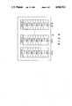
- FIG. 3shows the arrangement of a queue buffer used for communication control.
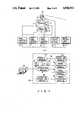
- FIG. 1shows the arrangement of a robot system according to an embodiment of the present invention.
- the robot systemhas, e.g., 7-degree-of-freedom arms 11 and 11', 6-degree-of-freedom dynamic amount measuring sensors 12 and 12', and 4-degree-of-freedom hands 13 and 13'.
- Stereo camera 15 for obtaining visual informationis provided above robot main body 10 through neck 14.
- Arm control module 16controls arms 11 and 11' in accordance with an arm control instruction.
- Right and left hand control modules 17 and 18control hands 13 and 13' in accordance with right and left hand control instructions, respectively.
- Head-eye control module 19controls swing of neck 14 in accordance with input control instructions.
- Image proccesing hardware module 20fetches image data in accordance with an input control instruction and transmits it.
- These peripheral control modules 16 to 20respectively have a function to transmit and receive data.
- Central control unit 30 for managing the operation of the overall robot systemis connected to terminal 40 and control modules 16 to 20 through external communication line 21.
- Terminal 40displays the processing results of respective control modules 16 to 20 and the processing results of the respective program modules 31 to 37 of control unit 30. Necessary information is entered as required from terminal 40 by an operator.
- Central control unit 30has supervisor module 31, work procedure generation modules 32 and 33, image processing modules 34 to 36, and communication module 37.
- Module 31sends various control instructions to modules 16 to 20 and 32 and 33 to progress the overall operations.
- Work procedure generation modules 32 and 33 and image processing modules 34 to 36serve as follows.
- Module 32generates the parts assembly sequence from the structure of an assembly sample.
- Module 33determines the operation sequences and operation amounts of the respective portions of the robot based on the parts assembly sequence.
- Module 34fetches images of the assembly sample and estimates its structure.
- Module 35detects a correction amount of a hand when a part is to be gripped.
- Module 36detects relative positions of parts when they are to be assembled.
- Communication module 37is connected to program modules 31 to 36 through internal communication system 38, and enables bidirectional communication among modules 31 to 36 in central control unit 30, among control modules 16 to 20, and between modules 31 to 36 and modules 16 to 20.
- Communication program module 37is connected to transmission request list 41, queue buffer 39, and queue list 42.
- Buffer 39has queue areas 39-16, 39-17, . . . , and 39-36 corresponding to respective modules 16 to 36, as shown in FIG. 3. Each area sequentially stores a source module name (S.M.) and a message (MES.). The status of the module is also stored.
- S.M.source module name
- MES.message
- the status of the moduleis also stored.
- a transmission requestis supplied, a number assigned to the module that has generated the transmission request is written in list 41. The number can be an identifier such as a module name.
- List 42indicates whether a message is stored in each area of buffer 39 by means of 1 bit, i.e., 1 or 0. The number of messages stored in each area can be written in list 42 instead of 1 or 0 to indicate the presence of messages.
- step S2module 37 monitors a transmission request from modules 16 to 20 and 31 to 36. If no transmission request is supplied, i.e., if NO in step S2, step S16 is executed. However, if YES in step S2, i.e., if a transmission request is supplied from e.g., module 16 to module 32 and from module 32 to module 17, numbers assigned to modules 16 and 32 are written in transmission request list 41 in step S4.
- step S6it is checked whether transmission request list 41 is empty. If NO in step S6, step S8 is executed, and the numbers stored in list 41 are read out starting from the head of list 41.
- step S10data is output from a module identified by its number, i.e., module 16 in this example.
- the dataincludes a destination module name and a message.
- a source module nameis discriminated from the assigned number.
- the source module name and received messageare written in area 39-32 of queue buffer 39 in accordance with the destination module name. In this case, when a message to be transmitted is already written in area 39-32, the source module name and message are written after it. Therefore, necessary data can be stored in buffer 39 while designating an appropriate destination module among modules 16 to 20 and 31 to 36.
- queue list 42is updated to include a message corresponding to module 32 in step S12.
- step S6is executed again. Since a transmission request supplied from module 32 is present in transmission request list 41, steps S8 to S12 are repeated in the same manner as described above.
- step S16is executed, and it is checked from queue list 42 whether a message to be transmitted is present in queue buffer 39. If a message to be transmitted is present in buffer 39, it is output from buffer 39 to a corresponding module in a predetermined order. In this example, the order is module 16-20 and then module 31-36.
- step S18it is first checked from queue list 41 whether a message destined to module 16 is present. If there is no such message, the same check is performed for module 17. If there is such a message, it is checked in step S20 whether destination module 17 is in an enabled state from the status written in area 39-17 of queue buffer 39. If NO in step S20, the flow returns to step S16.
- step S18Assume that the processing for each destination module has progressed and that checking is to be performed for module 32 in step S18.
- a message destined to module 32has been received in advance and written in queue buffer 39.
- NOis obtained in step S18 and it is checked in step S20 whether module 32 is in the enabled state. If YES in step S20, the message and the source module name that are read out from buffer 39 are transmitted to module 32 together with a destination module name in step S22. Then, queue list 42 is updated in step S24 and step S16 is executed. In this manner, a message is transmitted only once to each destination module.
- the enable/disable state of a corresponding one of modules 16 to 20 and 31 to 36is updated by transmitting the changed module state to the status of queue buffer 39 through module 37.
- steps S16 to S24are executed and a message is transmitted only once to each destination module.
- the transmission and reception sequences of each modulecan be kept unchanged. Since mutual communication among the respective modules is performed through module 37, the physical state of a destination module need not be considered, the entire arrangement can be simplified, and the flexibility of each module can be improved. Even when the system arrangement or the operating state is changed, only the program of module 37 need be modified and the information transmission path need not be modified. Modules 16 to 20 and 31 to 36 need not monitor the communication line, resulting in a simplified program. The same or different operation instructions can be supplied to a plurality of modules at once, and thus the parallel operations of the respective portions of the robot can be executed.
Landscapes
- Engineering & Computer Science (AREA)
- Human Computer Interaction (AREA)
- Manufacturing & Machinery (AREA)
- Physics & Mathematics (AREA)
- General Physics & Mathematics (AREA)
- Automation & Control Theory (AREA)
- Manipulator (AREA)
- Numerical Control (AREA)
- Selective Calling Equipment (AREA)
- Computer And Data Communications (AREA)
Abstract
Description
U.S. application Ser. No. 07/196.061 filed May 19, 1988 and U.S. application Ser. No. 97/196.063 filed May 19, 1988 are related applications.
1. Field of the Invention
The present invention relates to a robot system having a central control unit for managing the entire operation of the robot system and a plurality of peripheral control modules for controlling the operations of the respective portions of the robot. More particularly, the present invention relates to a communication control method of transmitting operation information among program modules of the central control unit, among control modules, and between the program modules and the control modules; and an apparatus for realizing the method.
Generally, along with widening in application range, both the mechanism and control systems of industrial robots have become complicated. Regarding the control system, it is divided into peripheral control modules for controlling the respective portions of the mechanism and signal processing and a central control unit for managing and controlling the entire operation.
Conventional industrial robots operate in accordance with a permanent work program. The peripheral equipment such as a sensor belongs to the robot controller and performs input/output of a simple signal in response to a communication instruction incorporated in the robot language.
In the conventional robot system, no serious problems occur when the robot performs a comparatively simple operation. However, when the robot system is a so-called multifunction system, it has a plurality of peripheral control modules for independently controlling the respective portions of the robot. It also includes in the central control unit a plurality of program modules, which can concurrently be performed to exchange instruction signals between any two of the control modules and the program modules. In such a multifunction system, the following problems arise.
Each peripheral control module and each program module of the central control unit must have a work program that can cope with any possible situation. As a result, when the operation of the robot system is changed, or when the operation sequence of each control module is changed, a new work program must be created.
Since the respective portions of the robot are controlled using instructions having simple contents, it is difficult for the robot to have a complicated function.
When a certain operation is instructed to a robot section and completion of the instructed operation is awaited, the central control unit and each program module must monitor a signal transmitted from the corresponding robot section in a program manner, and other program processes cannot be performed during this monitoring.
Furthermore, when each program processing module of the central control unit independently and parallelly processes the program, it cannot control a corresponding control module immediately based on the processing result if other processing modules use the communication line.
The present invention has been made in view of the above situation and has as its object to provide a communication control method of a robot system wherein when the arrangement of control modules is changed, a communication control can be performed without changing the program of each program module, when a new function is added to the robot, the method can sufficiently cope with it, and the operation of the respective portions of the robot can appropriately reflect the processing state, and a request of each module. The present invention also provides an apparatus for realizing the method.
The robot system according to the present invention comprises a plurality of program modules each for independently performing required program processing in the central control unit, a robot mechanism, and a plurality of control modules for controlling associated portions of the robot mechanism. In the robot system, communication is performed among program modules, among the control modules, and between the program modules and the peripheral control modules. For this purpose, in the present invention, a communication module is provided for performing communication management. Each module includes a data base on the connection style for communication with another module, a status buffer and a queue buffer for the modules. The status buffer stores the current status information of each module and the queue buffer sequentially stores the names of source modules, each of which has sent a message to a destination module, and stores the message itself.
When a certain message is to be transmitted from one module to another, the destination module name and the message are transmitted to the communication module. The communication module alternately monitors messages transmitted from modules within the system, and the state of the queue buffer. When a message is transmitted, the destination module name and the message are read in accordance with a reception procedure of the source module described in the connection style data base. Then, the source module name and the message are stored in the queue buffer of the destination module. The stored message is monitored and found in the queue buffer. When the status of the destination module is in the enabled state, the source module name and the message are transmitted to the destination module in accordance with the transfer procedure described in the connection style data base.
In this manner, according to the present invention, even if the arrangement of the control modules or program modules is altered, the control method can cope with it by altering the communication transfer status data base of the communication module. The message arrival order to a specific module is maintained at the reception order of the communication module by the queue. Therefore, even when a new function is added to the robot, the control method can sufficiently cope with it, and the respective portions of the robot can appropriately reflect the program processing state and request of each module.
FIG. 1 is a block diagram of a multifunction robot system according to an embodiment of the present invention;
FIG. 2 is a flowchart for explaining the operation of an intermodule communication control module; and
FIG. 3 shows the arrangement of a queue buffer used for communication control.
A robot system according to a preferred embodiment of the present invention will be described in detail with reference to the accompanying drawings.
FIG. 1 shows the arrangement of a robot system according to an embodiment of the present invention. Referring to FIG. 1, the robot system has, e.g., 7-degree-of-freedom arms 11 and 11', 6-degree-of-freedom dynamicamount measuring sensors 12 and 12', and 4-degree-of-freedom hands 13 and 13'.Stereo camera 15 for obtaining visual information is provided above robotmain body 10 throughneck 14.Arm control module 16 controlsarms 11 and 11' in accordance with an arm control instruction. Right and lefthand control modules control hands 13 and 13' in accordance with right and left hand control instructions, respectively. Head-eye control module 19 controls swing ofneck 14 in accordance with input control instructions. Image proccesinghardware module 20 fetches image data in accordance with an input control instruction and transmits it. Theseperipheral control modules 16 to 20 respectively have a function to transmit and receive data.
The operation of the robot system having the above arrangement will be described with reference to FIG. 2.
Instep S2 module 37 monitors a transmission request frommodules 16 to 20 and 31 to 36. If no transmission request is supplied, i.e., if NO in step S2, step S16 is executed. However, if YES in step S2, i.e., if a transmission request is supplied from e.g.,module 16 tomodule 32 and frommodule 32 tomodule 17, numbers assigned tomodules transmission request list 41 in step S4.
In step S6, it is checked whethertransmission request list 41 is empty. If NO in step S6, step S8 is executed, and the numbers stored inlist 41 are read out starting from the head oflist 41. In step S10, data is output from a module identified by its number, i.e.,module 16 in this example. The data includes a destination module name and a message. A source module name is discriminated from the assigned number. The source module name and received message are written in area 39-32 ofqueue buffer 39 in accordance with the destination module name. In this case, when a message to be transmitted is already written in area 39-32, the source module name and message are written after it. Therefore, necessary data can be stored inbuffer 39 while designating an appropriate destination module amongmodules 16 to 20 and 31 to 36. Then,queue list 42 is updated to include a message corresponding tomodule 32 in step S12.
Then, step S6 is executed again. Since a transmission request supplied frommodule 32 is present intransmission request list 41, steps S8 to S12 are repeated in the same manner as described above.
When it is determined in step S6 thattransmission request list 41 is empty, step S16 is executed, and it is checked fromqueue list 42 whether a message to be transmitted is present inqueue buffer 39. If a message to be transmitted is present inbuffer 39, it is output frombuffer 39 to a corresponding module in a predetermined order. In this example, the order is module 16-20 and then module 31-36.
In step S18, it is first checked fromqueue list 41 whether a message destined tomodule 16 is present. If there is no such message, the same check is performed formodule 17. If there is such a message, it is checked in step S20 whetherdestination module 17 is in an enabled state from the status written in area 39-17 ofqueue buffer 39. If NO in step S20, the flow returns to step S16.
Assume that the processing for each destination module has progressed and that checking is to be performed formodule 32 in step S18. A message destined tomodule 32 has been received in advance and written inqueue buffer 39. Thus, NO is obtained in step S18 and it is checked in step S20 whethermodule 32 is in the enabled state. If YES in step S20, the message and the source module name that are read out frombuffer 39 are transmitted tomodule 32 together with a destination module name in step S22. Then,queue list 42 is updated in step S24 and step S16 is executed. In this manner, a message is transmitted only once to each destination module. When a module status change occurs, the enable/disable state of a corresponding one ofmodules 16 to 20 and 31 to 36 is updated by transmitting the changed module state to the status ofqueue buffer 39 throughmodule 37.
When the flow returns to step S2 from step S16, if no transmission request is generated, steps S16 to S24 are executed and a message is transmitted only once to each destination module.
In the embodiment described above, the transmission and reception sequences of each module can be kept unchanged. Since mutual communication among the respective modules is performed throughmodule 37, the physical state of a destination module need not be considered, the entire arrangement can be simplified, and the flexibility of each module can be improved. Even when the system arrangement or the operating state is changed, only the program ofmodule 37 need be modified and the information transmission path need not be modified.Modules 16 to 20 and 31 to 36 need not monitor the communication line, resulting in a simplified program. The same or different operation instructions can be supplied to a plurality of modules at once, and thus the parallel operations of the respective portions of the robot can be executed.
When the program modules are increased in size, a plurality of central control units can be coupled through a communication module and an increase in communicational complexity can be prevented. Moreover, various changes and modifications can be made within the spirit and scope of the invention.
Claims (9)
1. A method for controlling a robot system having a commander and a plurality of modules, comprising the steps of:
generating one or more requests to transmit one or more messages from a source module to a destination module;
inputting the transmission requests to the commander;
placing the transmission requests into a sequential list of transmission requests;
writing the messages into queue buffers, corresponding to the destination modules, until the sequential list is depleted; and
transmitting one messages from each of the queue buffers to the corresponding destination modules in a predetermined order.
2. A method according to claim 1, further including the step, after the step of transmitting, of:
repeating the steps of generating, inputting, placing, writing, and transmitting.
3. A method according to claim 2, further including:
after the step of placing, generating a status list identifying the status of each queue buffer as either containing at least one message or containing no message; and
during the step of writing, checking the status list and placing messages in queue buffers, which already contain one or more messages, in sequential order.
4. A method according to claim 1, wherein the step of generating is performed in accordance with a work procedure for the robot system.
5. A method according to claim 1, wherein the step of transmitting includes:
checking whether a destination module is busy; and
transmitting the message from the queue buffer corresponding to the destination module only if the destination module is not busy.
6. A robot system, comprising:
a plurality of modules, each module capable of acting as a source module of a message and as a destination module of a message, each module including means for generating transmission requests and for generating messages to be sent to other modules, and
a commander in communication with the plurality of modules, including:
means for receiving the transmission requests and messages from the modules,
a sequential list memory for storing the received transmission requests in sequential order,
a plurality of queue buffers, corresponding to the plurality of modules, capable of storing the messages to be sent to particular destination modules in the buffers corresponding to the particular destination modules, and
means for transmitting one messages from each of the queue buffers to the destination modules corresponding to the queue buffers, in a predetermined order.
7. A system according to claim 6, wherein the commander further includes:
means for determining whether a particular queue buffer contains a previous message and, if a queue buffer contains a previous message, for placing a subsequent message in the queue buffer with the previous message, in sequential order.
8. A system according to claim 6, wherein each module further includes means for generating messages in accordance with a work procedure for the robot system.
9. A system according to claim 6, wherein the commander further includes:
means for determining whether a destination module is busy; and
means for transmitting a message to a particular destination module only if the particular destination module is not busy.
Applications Claiming Priority (2)
| Application Number | Priority Date | Filing Date | Title |
|---|---|---|---|
| JP62124604AJPS63289607A (en) | 1987-05-21 | 1987-05-21 | Inter-module communication control system for intelligent robot |
| JP62-124604 | 1987-05-21 |
Publications (1)
| Publication Number | Publication Date |
|---|---|
| US4942512Atrue US4942512A (en) | 1990-07-17 |
Family
ID=14889550
Family Applications (1)
| Application Number | Title | Priority Date | Filing Date |
|---|---|---|---|
| US07/196,063Expired - Fee RelatedUS4942512A (en) | 1987-05-21 | 1988-05-19 | Control method of robot system and apparatus for realizing the same |
Country Status (5)
| Country | Link |
|---|---|
| US (1) | US4942512A (en) |
| EP (1) | EP0291966B1 (en) |
| JP (1) | JPS63289607A (en) |
| KR (1) | KR910000872B1 (en) |
| DE (1) | DE3873411T2 (en) |
Cited By (54)
| Publication number | Priority date | Publication date | Assignee | Title |
|---|---|---|---|---|
| US5031109A (en)* | 1987-12-14 | 1991-07-09 | Gemplus Card International | System for controlling a wandering robot |
| US5300869A (en)* | 1992-07-30 | 1994-04-05 | Iowa State University Research Foundation, Inc. | Nonholonomic camera space manipulation |
| US20070108109A1 (en)* | 2003-06-26 | 2007-05-17 | Abb Ab | Control method for machines, including a system, computer program, data signal and gui |
| US20070291128A1 (en)* | 2006-06-15 | 2007-12-20 | Yulun Wang | Mobile teleconferencing system that projects an image provided by a mobile robot |
| US20080065268A1 (en)* | 2002-07-25 | 2008-03-13 | Yulun Wang | Medical Tele-robotic system with a master remote station with an arbitrator |
| US20090105882A1 (en)* | 2002-07-25 | 2009-04-23 | Intouch Technologies, Inc. | Medical Tele-Robotic System |
| US20100010671A1 (en)* | 2008-07-14 | 2010-01-14 | Atsushi Miyamoto | Information processing system, information processing method, robot control system, robot control method, and computer program |
| US20100191375A1 (en)* | 2009-01-29 | 2010-07-29 | Wright Timothy C | Documentation through a remote presence robot |
| US8000837B2 (en) | 2004-10-05 | 2011-08-16 | J&L Group International, Llc | Programmable load forming system, components thereof, and methods of use |
| US20110213210A1 (en)* | 2009-08-26 | 2011-09-01 | Intouch Technologies, Inc. | Portable telepresence apparatus |
| US8340819B2 (en) | 2008-09-18 | 2012-12-25 | Intouch Technologies, Inc. | Mobile videoconferencing robot system with network adaptive driving |
| US8401275B2 (en) | 2004-07-13 | 2013-03-19 | Intouch Technologies, Inc. | Mobile robot with a head-based movement mapping scheme |
| US8650538B2 (en) | 2012-05-01 | 2014-02-11 | Concurix Corporation | Meta garbage collection for functional code |
| US8670017B2 (en) | 2010-03-04 | 2014-03-11 | Intouch Technologies, Inc. | Remote presence system including a cart that supports a robot face and an overhead camera |
| US8726255B2 (en) | 2012-05-01 | 2014-05-13 | Concurix Corporation | Recompiling with generic to specific replacement |
| CN103846915A (en)* | 2012-11-29 | 2014-06-11 | 株式会社大亨 | Robot system |
| US8793669B2 (en) | 2012-07-17 | 2014-07-29 | Concurix Corporation | Pattern extraction from executable code in message passing environments |
| US8836751B2 (en) | 2011-11-08 | 2014-09-16 | Intouch Technologies, Inc. | Tele-presence system with a user interface that displays different communication links |
| US8849679B2 (en) | 2006-06-15 | 2014-09-30 | Intouch Technologies, Inc. | Remote controlled robot system that provides medical images |
| US8861750B2 (en) | 2008-04-17 | 2014-10-14 | Intouch Technologies, Inc. | Mobile tele-presence system with a microphone system |
| US8897920B2 (en) | 2009-04-17 | 2014-11-25 | Intouch Technologies, Inc. | Tele-presence robot system with software modularity, projector and laser pointer |
| US8902278B2 (en) | 2012-04-11 | 2014-12-02 | Intouch Technologies, Inc. | Systems and methods for visualizing and managing telepresence devices in healthcare networks |
| US8965579B2 (en) | 2011-01-28 | 2015-02-24 | Intouch Technologies | Interfacing with a mobile telepresence robot |
| US8996165B2 (en) | 2008-10-21 | 2015-03-31 | Intouch Technologies, Inc. | Telepresence robot with a camera boom |
| US9098611B2 (en) | 2012-11-26 | 2015-08-04 | Intouch Technologies, Inc. | Enhanced video interaction for a user interface of a telepresence network |
| US9138891B2 (en) | 2008-11-25 | 2015-09-22 | Intouch Technologies, Inc. | Server connectivity control for tele-presence robot |
| US9160783B2 (en) | 2007-05-09 | 2015-10-13 | Intouch Technologies, Inc. | Robot system that operates through a network firewall |
| US9174342B2 (en) | 2012-05-22 | 2015-11-03 | Intouch Technologies, Inc. | Social behavior rules for a medical telepresence robot |
| US9193065B2 (en) | 2008-07-10 | 2015-11-24 | Intouch Technologies, Inc. | Docking system for a tele-presence robot |
| US9198728B2 (en) | 2005-09-30 | 2015-12-01 | Intouch Technologies, Inc. | Multi-camera mobile teleconferencing platform |
| US9251313B2 (en) | 2012-04-11 | 2016-02-02 | Intouch Technologies, Inc. | Systems and methods for visualizing and managing telepresence devices in healthcare networks |
| US9264664B2 (en) | 2010-12-03 | 2016-02-16 | Intouch Technologies, Inc. | Systems and methods for dynamic bandwidth allocation |
| US9296107B2 (en) | 2003-12-09 | 2016-03-29 | Intouch Technologies, Inc. | Protocol for a remotely controlled videoconferencing robot |
| CN105488892A (en)* | 2016-01-04 | 2016-04-13 | 杭州亚美利嘉科技有限公司 | Method and server for robot queuing management |
| US9323250B2 (en) | 2011-01-28 | 2016-04-26 | Intouch Technologies, Inc. | Time-dependent navigation of telepresence robots |
| US9361021B2 (en) | 2012-05-22 | 2016-06-07 | Irobot Corporation | Graphical user interfaces including touchpad driving interfaces for telemedicine devices |
| US9575813B2 (en) | 2012-07-17 | 2017-02-21 | Microsoft Technology Licensing, Llc | Pattern matching process scheduler with upstream optimization |
| US9602765B2 (en) | 2009-08-26 | 2017-03-21 | Intouch Technologies, Inc. | Portable remote presence robot |
| US9610685B2 (en) | 2004-02-26 | 2017-04-04 | Intouch Technologies, Inc. | Graphical interface for a remote presence system |
| US9842192B2 (en) | 2008-07-11 | 2017-12-12 | Intouch Technologies, Inc. | Tele-presence robot system with multi-cast features |
| US9974612B2 (en) | 2011-05-19 | 2018-05-22 | Intouch Technologies, Inc. | Enhanced diagnostics for a telepresence robot |
| US10059000B2 (en) | 2008-11-25 | 2018-08-28 | Intouch Technologies, Inc. | Server connectivity control for a tele-presence robot |
| US10343283B2 (en) | 2010-05-24 | 2019-07-09 | Intouch Technologies, Inc. | Telepresence robot system that can be accessed by a cellular phone |
| US10471588B2 (en) | 2008-04-14 | 2019-11-12 | Intouch Technologies, Inc. | Robotic based health care system |
| US10769739B2 (en) | 2011-04-25 | 2020-09-08 | Intouch Technologies, Inc. | Systems and methods for management of information among medical providers and facilities |
| US10808882B2 (en) | 2010-05-26 | 2020-10-20 | Intouch Technologies, Inc. | Tele-robotic system with a robot face placed on a chair |
| US10875182B2 (en) | 2008-03-20 | 2020-12-29 | Teladoc Health, Inc. | Remote presence system mounted to operating room hardware |
| US11154981B2 (en) | 2010-02-04 | 2021-10-26 | Teladoc Health, Inc. | Robot user interface for telepresence robot system |
| US11389064B2 (en) | 2018-04-27 | 2022-07-19 | Teladoc Health, Inc. | Telehealth cart that supports a removable tablet with seamless audio/video switching |
| US11636944B2 (en) | 2017-08-25 | 2023-04-25 | Teladoc Health, Inc. | Connectivity infrastructure for a telehealth platform |
| US11742094B2 (en) | 2017-07-25 | 2023-08-29 | Teladoc Health, Inc. | Modular telehealth cart with thermal imaging and touch screen user interface |
| US11862302B2 (en) | 2017-04-24 | 2024-01-02 | Teladoc Health, Inc. | Automated transcription and documentation of tele-health encounters |
| US12093036B2 (en) | 2011-01-21 | 2024-09-17 | Teladoc Health, Inc. | Telerobotic system with a dual application screen presentation |
| US12224059B2 (en) | 2011-02-16 | 2025-02-11 | Teladoc Health, Inc. | Systems and methods for network-based counseling |
Families Citing this family (5)
| Publication number | Priority date | Publication date | Assignee | Title |
|---|---|---|---|---|
| JPH01282606A (en)* | 1988-05-10 | 1989-11-14 | Fanuc Ltd | Pmc device |
| US4990839A (en)* | 1988-12-09 | 1991-02-05 | Schonlau William J | Modular robotic system |
| US5055755A (en)* | 1989-05-31 | 1991-10-08 | Kabushiki Kaisha Toshiba | Distribution control apparatus |
| JP5098456B2 (en)* | 2007-06-15 | 2012-12-12 | 村田機械株式会社 | Process status monitoring device |
| KR102235166B1 (en) | 2015-09-21 | 2021-04-02 | 주식회사 레인보우로보틱스 | A realtime robot system, an appratus for controlling a robot system, and a method for controlling a robot system |
Citations (12)
| Publication number | Priority date | Publication date | Assignee | Title |
|---|---|---|---|---|
| EP0022622A1 (en)* | 1979-06-19 | 1981-01-21 | Gould Inc. | Programmable controller |
| WO1983001520A1 (en)* | 1981-10-26 | 1983-04-28 | Us Robots Inc | Robot arm controller with common bus memory |
| EP0090302A1 (en)* | 1982-03-30 | 1983-10-05 | Cincinnati Milacron Inc. | Programmable control apparatus and method |
| US4428043A (en)* | 1981-08-24 | 1984-01-24 | Burroughs Corporation | Data communications network |
| EP0162670A2 (en)* | 1984-05-19 | 1985-11-27 | British Aerospace Public Limited Company | Industrial processing and manufacturing systems |
| JPS60256875A (en)* | 1984-06-01 | 1985-12-18 | Mitsubishi Electric Corp | Picture processor |
| JPS61117605A (en)* | 1984-11-14 | 1986-06-05 | Hitachi Ltd | Robot control method |
| US4600988A (en)* | 1982-09-30 | 1986-07-15 | Siemens Aktiengesellschaft | Memory-programmable control |
| US4607256A (en)* | 1983-10-07 | 1986-08-19 | Honeywell, Inc. | Plant management system |
| EP0201081A2 (en)* | 1985-05-10 | 1986-11-12 | Hitachi, Ltd. | Control apparatus |
| US4658351A (en)* | 1984-10-09 | 1987-04-14 | Wang Laboratories, Inc. | Task control means for a multi-tasking data processing system |
| US4706120A (en)* | 1985-08-30 | 1987-11-10 | Texas Instruments Incorporated | Modular, vision system for automation of inspection and process control |
- 1987
- 1987-05-21JPJP62124604Apatent/JPS63289607A/enactivePending
- 1988
- 1988-05-18EPEP88107983Apatent/EP0291966B1/ennot_activeExpired - Lifetime
- 1988-05-18DEDE8888107983Tpatent/DE3873411T2/ennot_activeExpired - Fee Related
- 1988-05-19USUS07/196,063patent/US4942512A/ennot_activeExpired - Fee Related
- 1988-05-21KRKR1019880006068Apatent/KR910000872B1/ennot_activeExpired
Patent Citations (12)
| Publication number | Priority date | Publication date | Assignee | Title |
|---|---|---|---|---|
| EP0022622A1 (en)* | 1979-06-19 | 1981-01-21 | Gould Inc. | Programmable controller |
| US4428043A (en)* | 1981-08-24 | 1984-01-24 | Burroughs Corporation | Data communications network |
| WO1983001520A1 (en)* | 1981-10-26 | 1983-04-28 | Us Robots Inc | Robot arm controller with common bus memory |
| EP0090302A1 (en)* | 1982-03-30 | 1983-10-05 | Cincinnati Milacron Inc. | Programmable control apparatus and method |
| US4600988A (en)* | 1982-09-30 | 1986-07-15 | Siemens Aktiengesellschaft | Memory-programmable control |
| US4607256A (en)* | 1983-10-07 | 1986-08-19 | Honeywell, Inc. | Plant management system |
| EP0162670A2 (en)* | 1984-05-19 | 1985-11-27 | British Aerospace Public Limited Company | Industrial processing and manufacturing systems |
| JPS60256875A (en)* | 1984-06-01 | 1985-12-18 | Mitsubishi Electric Corp | Picture processor |
| US4658351A (en)* | 1984-10-09 | 1987-04-14 | Wang Laboratories, Inc. | Task control means for a multi-tasking data processing system |
| JPS61117605A (en)* | 1984-11-14 | 1986-06-05 | Hitachi Ltd | Robot control method |
| EP0201081A2 (en)* | 1985-05-10 | 1986-11-12 | Hitachi, Ltd. | Control apparatus |
| US4706120A (en)* | 1985-08-30 | 1987-11-10 | Texas Instruments Incorporated | Modular, vision system for automation of inspection and process control |
Non-Patent Citations (8)
| Title |
|---|
| "A Petri net based Controller for Flexible and Maintainable Sequence Control and its Application in Factory Automation", IEEE Trans. Industrial electronics IE-33.1; T. Murata, et al.; 1986, This article proposes a new type controller based on a Petri Net (a kind of directed graph) like control language. |
| "Proposal of Mark Flow Graph for Discrete System Contol", (in Japan) Trans of SICE, 2-2; K. Hasegawa, et al., 1983, This article proposes a concept of Mark Flow Graph (a kind of directed graph which can represent control logic for sequential control systems). |
| A Petri net based Controller for Flexible and Maintainable Sequence Control and its Application in Factory Automation , IEEE Trans. Industrial electronics IE 33.1; T. Murata, et al.; 1986, This article proposes a new type controller based on a Petri Net (a kind of directed graph) like control language.* |
| Proc. IECON 86; M. Nagata; 1986, IEEE Interprocess Communication for Robot Control .* |
| Proc. IECON'86; M. Nagata; 1986, IEEE "Interprocess Communication for Robot Control". |
| Proposal of Mark Flow Graph for Discrete System Contol , (in Japan) Trans of SICE, 2 2; K. Hasegawa, et al., 1983, This article proposes a concept of Mark Flow Graph (a kind of directed graph which can represent control logic for sequential control systems).* |
| T. Tanaka, et al., Robot Planner: Design and Programming support System for Planning of Robot Operation Basic concept and Development Toshiba Corporation, pp. cover (v), 283 286.* |
| T. Tanaka, et al., Robot Planner: Design and Programming support System for Planning of Robot Operation-Basic concept and Development-Toshiba Corporation, pp. cover (v), 283-286. |
Cited By (114)
| Publication number | Priority date | Publication date | Assignee | Title |
|---|---|---|---|---|
| US5031109A (en)* | 1987-12-14 | 1991-07-09 | Gemplus Card International | System for controlling a wandering robot |
| US5300869A (en)* | 1992-07-30 | 1994-04-05 | Iowa State University Research Foundation, Inc. | Nonholonomic camera space manipulation |
| US20210241902A1 (en)* | 2002-07-25 | 2021-08-05 | Teladoc Health, Inc. | Medical tele-robotic system with a master remote station with an arbitrator |
| US20080065268A1 (en)* | 2002-07-25 | 2008-03-13 | Yulun Wang | Medical Tele-robotic system with a master remote station with an arbitrator |
| US20090105882A1 (en)* | 2002-07-25 | 2009-04-23 | Intouch Technologies, Inc. | Medical Tele-Robotic System |
| USRE45870E1 (en) | 2002-07-25 | 2016-01-26 | Intouch Technologies, Inc. | Apparatus and method for patient rounding with a remote controlled robot |
| US20190248018A1 (en)* | 2002-07-25 | 2019-08-15 | Intouch Technologies, Inc. | Medical tele-robotic system with a master remote station with an arbitrator |
| US10315312B2 (en)* | 2002-07-25 | 2019-06-11 | Intouch Technologies, Inc. | Medical tele-robotic system with a master remote station with an arbitrator |
| US8682486B2 (en)* | 2002-07-25 | 2014-03-25 | Intouch Technologies, Inc. | Medical tele-robotic system with a master remote station with an arbitrator |
| US10889000B2 (en)* | 2002-07-25 | 2021-01-12 | Teladoc Health | Medical tele-robotic system with a master remote station with an arbitrator |
| US9849593B2 (en)* | 2002-07-25 | 2017-12-26 | Intouch Technologies, Inc. | Medical tele-robotic system with a master remote station with an arbitrator |
| US8515577B2 (en)* | 2002-07-25 | 2013-08-20 | Yulun Wang | Medical tele-robotic system with a master remote station with an arbitrator |
| US20130304257A1 (en)* | 2002-07-25 | 2013-11-14 | Intouch Technologies, Inc. | Medical tele-robotic system with a master remote station with an arbitrator |
| US20070108109A1 (en)* | 2003-06-26 | 2007-05-17 | Abb Ab | Control method for machines, including a system, computer program, data signal and gui |
| US8417363B2 (en)* | 2003-06-26 | 2013-04-09 | Abb Ab | Control method for machines, including a system, computer program, data signal and gui |
| US9956690B2 (en) | 2003-12-09 | 2018-05-01 | Intouch Technologies, Inc. | Protocol for a remotely controlled videoconferencing robot |
| US10882190B2 (en) | 2003-12-09 | 2021-01-05 | Teladoc Health, Inc. | Protocol for a remotely controlled videoconferencing robot |
| US9296107B2 (en) | 2003-12-09 | 2016-03-29 | Intouch Technologies, Inc. | Protocol for a remotely controlled videoconferencing robot |
| US9375843B2 (en) | 2003-12-09 | 2016-06-28 | Intouch Technologies, Inc. | Protocol for a remotely controlled videoconferencing robot |
| US9610685B2 (en) | 2004-02-26 | 2017-04-04 | Intouch Technologies, Inc. | Graphical interface for a remote presence system |
| US10241507B2 (en) | 2004-07-13 | 2019-03-26 | Intouch Technologies, Inc. | Mobile robot with a head-based movement mapping scheme |
| US8401275B2 (en) | 2004-07-13 | 2013-03-19 | Intouch Technologies, Inc. | Mobile robot with a head-based movement mapping scheme |
| US9766624B2 (en) | 2004-07-13 | 2017-09-19 | Intouch Technologies, Inc. | Mobile robot with a head-based movement mapping scheme |
| US8983174B2 (en) | 2004-07-13 | 2015-03-17 | Intouch Technologies, Inc. | Mobile robot with a head-based movement mapping scheme |
| US8000837B2 (en) | 2004-10-05 | 2011-08-16 | J&L Group International, Llc | Programmable load forming system, components thereof, and methods of use |
| US9198728B2 (en) | 2005-09-30 | 2015-12-01 | Intouch Technologies, Inc. | Multi-camera mobile teleconferencing platform |
| US10259119B2 (en) | 2005-09-30 | 2019-04-16 | Intouch Technologies, Inc. | Multi-camera mobile teleconferencing platform |
| US20070291128A1 (en)* | 2006-06-15 | 2007-12-20 | Yulun Wang | Mobile teleconferencing system that projects an image provided by a mobile robot |
| US8849679B2 (en) | 2006-06-15 | 2014-09-30 | Intouch Technologies, Inc. | Remote controlled robot system that provides medical images |
| US10682763B2 (en) | 2007-05-09 | 2020-06-16 | Intouch Technologies, Inc. | Robot system that operates through a network firewall |
| US9160783B2 (en) | 2007-05-09 | 2015-10-13 | Intouch Technologies, Inc. | Robot system that operates through a network firewall |
| US10875182B2 (en) | 2008-03-20 | 2020-12-29 | Teladoc Health, Inc. | Remote presence system mounted to operating room hardware |
| US11787060B2 (en) | 2008-03-20 | 2023-10-17 | Teladoc Health, Inc. | Remote presence system mounted to operating room hardware |
| US10471588B2 (en) | 2008-04-14 | 2019-11-12 | Intouch Technologies, Inc. | Robotic based health care system |
| US11472021B2 (en) | 2008-04-14 | 2022-10-18 | Teladoc Health, Inc. | Robotic based health care system |
| US8861750B2 (en) | 2008-04-17 | 2014-10-14 | Intouch Technologies, Inc. | Mobile tele-presence system with a microphone system |
| US10493631B2 (en) | 2008-07-10 | 2019-12-03 | Intouch Technologies, Inc. | Docking system for a tele-presence robot |
| US9193065B2 (en) | 2008-07-10 | 2015-11-24 | Intouch Technologies, Inc. | Docking system for a tele-presence robot |
| US10878960B2 (en) | 2008-07-11 | 2020-12-29 | Teladoc Health, Inc. | Tele-presence robot system with multi-cast features |
| US9842192B2 (en) | 2008-07-11 | 2017-12-12 | Intouch Technologies, Inc. | Tele-presence robot system with multi-cast features |
| US20100010671A1 (en)* | 2008-07-14 | 2010-01-14 | Atsushi Miyamoto | Information processing system, information processing method, robot control system, robot control method, and computer program |
| US8340819B2 (en) | 2008-09-18 | 2012-12-25 | Intouch Technologies, Inc. | Mobile videoconferencing robot system with network adaptive driving |
| US9429934B2 (en) | 2008-09-18 | 2016-08-30 | Intouch Technologies, Inc. | Mobile videoconferencing robot system with network adaptive driving |
| US8996165B2 (en) | 2008-10-21 | 2015-03-31 | Intouch Technologies, Inc. | Telepresence robot with a camera boom |
| US9138891B2 (en) | 2008-11-25 | 2015-09-22 | Intouch Technologies, Inc. | Server connectivity control for tele-presence robot |
| US12138808B2 (en) | 2008-11-25 | 2024-11-12 | Teladoc Health, Inc. | Server connectivity control for tele-presence robots |
| US10875183B2 (en) | 2008-11-25 | 2020-12-29 | Teladoc Health, Inc. | Server connectivity control for tele-presence robot |
| US10059000B2 (en) | 2008-11-25 | 2018-08-28 | Intouch Technologies, Inc. | Server connectivity control for a tele-presence robot |
| US20100191375A1 (en)* | 2009-01-29 | 2010-07-29 | Wright Timothy C | Documentation through a remote presence robot |
| US8849680B2 (en) | 2009-01-29 | 2014-09-30 | Intouch Technologies, Inc. | Documentation through a remote presence robot |
| US8897920B2 (en) | 2009-04-17 | 2014-11-25 | Intouch Technologies, Inc. | Tele-presence robot system with software modularity, projector and laser pointer |
| US10969766B2 (en) | 2009-04-17 | 2021-04-06 | Teladoc Health, Inc. | Tele-presence robot system with software modularity, projector and laser pointer |
| US20110213210A1 (en)* | 2009-08-26 | 2011-09-01 | Intouch Technologies, Inc. | Portable telepresence apparatus |
| US10911715B2 (en) | 2009-08-26 | 2021-02-02 | Teladoc Health, Inc. | Portable remote presence robot |
| US10404939B2 (en) | 2009-08-26 | 2019-09-03 | Intouch Technologies, Inc. | Portable remote presence robot |
| US9602765B2 (en) | 2009-08-26 | 2017-03-21 | Intouch Technologies, Inc. | Portable remote presence robot |
| US11399153B2 (en) | 2009-08-26 | 2022-07-26 | Teladoc Health, Inc. | Portable telepresence apparatus |
| US11154981B2 (en) | 2010-02-04 | 2021-10-26 | Teladoc Health, Inc. | Robot user interface for telepresence robot system |
| US9089972B2 (en) | 2010-03-04 | 2015-07-28 | Intouch Technologies, Inc. | Remote presence system including a cart that supports a robot face and an overhead camera |
| US10887545B2 (en) | 2010-03-04 | 2021-01-05 | Teladoc Health, Inc. | Remote presence system including a cart that supports a robot face and an overhead camera |
| US8670017B2 (en) | 2010-03-04 | 2014-03-11 | Intouch Technologies, Inc. | Remote presence system including a cart that supports a robot face and an overhead camera |
| US11798683B2 (en) | 2010-03-04 | 2023-10-24 | Teladoc Health, Inc. | Remote presence system including a cart that supports a robot face and an overhead camera |
| US11389962B2 (en) | 2010-05-24 | 2022-07-19 | Teladoc Health, Inc. | Telepresence robot system that can be accessed by a cellular phone |
| US10343283B2 (en) | 2010-05-24 | 2019-07-09 | Intouch Technologies, Inc. | Telepresence robot system that can be accessed by a cellular phone |
| US10808882B2 (en) | 2010-05-26 | 2020-10-20 | Intouch Technologies, Inc. | Tele-robotic system with a robot face placed on a chair |
| US9264664B2 (en) | 2010-12-03 | 2016-02-16 | Intouch Technologies, Inc. | Systems and methods for dynamic bandwidth allocation |
| US10218748B2 (en) | 2010-12-03 | 2019-02-26 | Intouch Technologies, Inc. | Systems and methods for dynamic bandwidth allocation |
| US12093036B2 (en) | 2011-01-21 | 2024-09-17 | Teladoc Health, Inc. | Telerobotic system with a dual application screen presentation |
| US9469030B2 (en) | 2011-01-28 | 2016-10-18 | Intouch Technologies | Interfacing with a mobile telepresence robot |
| US8965579B2 (en) | 2011-01-28 | 2015-02-24 | Intouch Technologies | Interfacing with a mobile telepresence robot |
| US9785149B2 (en) | 2011-01-28 | 2017-10-10 | Intouch Technologies, Inc. | Time-dependent navigation of telepresence robots |
| US10399223B2 (en) | 2011-01-28 | 2019-09-03 | Intouch Technologies, Inc. | Interfacing with a mobile telepresence robot |
| US9323250B2 (en) | 2011-01-28 | 2016-04-26 | Intouch Technologies, Inc. | Time-dependent navigation of telepresence robots |
| US11468983B2 (en) | 2011-01-28 | 2022-10-11 | Teladoc Health, Inc. | Time-dependent navigation of telepresence robots |
| US10591921B2 (en) | 2011-01-28 | 2020-03-17 | Intouch Technologies, Inc. | Time-dependent navigation of telepresence robots |
| US11289192B2 (en) | 2011-01-28 | 2022-03-29 | Intouch Technologies, Inc. | Interfacing with a mobile telepresence robot |
| US12224059B2 (en) | 2011-02-16 | 2025-02-11 | Teladoc Health, Inc. | Systems and methods for network-based counseling |
| US10769739B2 (en) | 2011-04-25 | 2020-09-08 | Intouch Technologies, Inc. | Systems and methods for management of information among medical providers and facilities |
| US9974612B2 (en) | 2011-05-19 | 2018-05-22 | Intouch Technologies, Inc. | Enhanced diagnostics for a telepresence robot |
| US10331323B2 (en) | 2011-11-08 | 2019-06-25 | Intouch Technologies, Inc. | Tele-presence system with a user interface that displays different communication links |
| US8836751B2 (en) | 2011-11-08 | 2014-09-16 | Intouch Technologies, Inc. | Tele-presence system with a user interface that displays different communication links |
| US9715337B2 (en) | 2011-11-08 | 2017-07-25 | Intouch Technologies, Inc. | Tele-presence system with a user interface that displays different communication links |
| US10762170B2 (en) | 2012-04-11 | 2020-09-01 | Intouch Technologies, Inc. | Systems and methods for visualizing patient and telepresence device statistics in a healthcare network |
| US9251313B2 (en) | 2012-04-11 | 2016-02-02 | Intouch Technologies, Inc. | Systems and methods for visualizing and managing telepresence devices in healthcare networks |
| US8902278B2 (en) | 2012-04-11 | 2014-12-02 | Intouch Technologies, Inc. | Systems and methods for visualizing and managing telepresence devices in healthcare networks |
| US11205510B2 (en) | 2012-04-11 | 2021-12-21 | Teladoc Health, Inc. | Systems and methods for visualizing and managing telepresence devices in healthcare networks |
| US8726255B2 (en) | 2012-05-01 | 2014-05-13 | Concurix Corporation | Recompiling with generic to specific replacement |
| US8650538B2 (en) | 2012-05-01 | 2014-02-11 | Concurix Corporation | Meta garbage collection for functional code |
| US10603792B2 (en) | 2012-05-22 | 2020-03-31 | Intouch Technologies, Inc. | Clinical workflows utilizing autonomous and semiautonomous telemedicine devices |
| US11453126B2 (en) | 2012-05-22 | 2022-09-27 | Teladoc Health, Inc. | Clinical workflows utilizing autonomous and semi-autonomous telemedicine devices |
| US10061896B2 (en) | 2012-05-22 | 2018-08-28 | Intouch Technologies, Inc. | Graphical user interfaces including touchpad driving interfaces for telemedicine devices |
| US10780582B2 (en) | 2012-05-22 | 2020-09-22 | Intouch Technologies, Inc. | Social behavior rules for a medical telepresence robot |
| US9361021B2 (en) | 2012-05-22 | 2016-06-07 | Irobot Corporation | Graphical user interfaces including touchpad driving interfaces for telemedicine devices |
| US9776327B2 (en) | 2012-05-22 | 2017-10-03 | Intouch Technologies, Inc. | Social behavior rules for a medical telepresence robot |
| US10892052B2 (en) | 2012-05-22 | 2021-01-12 | Intouch Technologies, Inc. | Graphical user interfaces including touchpad driving interfaces for telemedicine devices |
| US10658083B2 (en) | 2012-05-22 | 2020-05-19 | Intouch Technologies, Inc. | Graphical user interfaces including touchpad driving interfaces for telemedicine devices |
| US10328576B2 (en) | 2012-05-22 | 2019-06-25 | Intouch Technologies, Inc. | Social behavior rules for a medical telepresence robot |
| US11628571B2 (en) | 2012-05-22 | 2023-04-18 | Teladoc Health, Inc. | Social behavior rules for a medical telepresence robot |
| US11515049B2 (en) | 2012-05-22 | 2022-11-29 | Teladoc Health, Inc. | Graphical user interfaces including touchpad driving interfaces for telemedicine devices |
| US9174342B2 (en) | 2012-05-22 | 2015-11-03 | Intouch Technologies, Inc. | Social behavior rules for a medical telepresence robot |
| US8793669B2 (en) | 2012-07-17 | 2014-07-29 | Concurix Corporation | Pattern extraction from executable code in message passing environments |
| US9575813B2 (en) | 2012-07-17 | 2017-02-21 | Microsoft Technology Licensing, Llc | Pattern matching process scheduler with upstream optimization |
| US9747086B2 (en) | 2012-07-17 | 2017-08-29 | Microsoft Technology Licensing, Llc | Transmission point pattern extraction from executable code in message passing environments |
| US11910128B2 (en) | 2012-11-26 | 2024-02-20 | Teladoc Health, Inc. | Enhanced video interaction for a user interface of a telepresence network |
| US10334205B2 (en) | 2012-11-26 | 2019-06-25 | Intouch Technologies, Inc. | Enhanced video interaction for a user interface of a telepresence network |
| US9098611B2 (en) | 2012-11-26 | 2015-08-04 | Intouch Technologies, Inc. | Enhanced video interaction for a user interface of a telepresence network |
| US10924708B2 (en) | 2012-11-26 | 2021-02-16 | Teladoc Health, Inc. | Enhanced video interaction for a user interface of a telepresence network |
| CN103846915B (en)* | 2012-11-29 | 2017-05-10 | 株式会社大亨 | Robot system |
| CN103846915A (en)* | 2012-11-29 | 2014-06-11 | 株式会社大亨 | Robot system |
| CN105488892A (en)* | 2016-01-04 | 2016-04-13 | 杭州亚美利嘉科技有限公司 | Method and server for robot queuing management |
| US11862302B2 (en) | 2017-04-24 | 2024-01-02 | Teladoc Health, Inc. | Automated transcription and documentation of tele-health encounters |
| US11742094B2 (en) | 2017-07-25 | 2023-08-29 | Teladoc Health, Inc. | Modular telehealth cart with thermal imaging and touch screen user interface |
| US11636944B2 (en) | 2017-08-25 | 2023-04-25 | Teladoc Health, Inc. | Connectivity infrastructure for a telehealth platform |
| US11389064B2 (en) | 2018-04-27 | 2022-07-19 | Teladoc Health, Inc. | Telehealth cart that supports a removable tablet with seamless audio/video switching |
Also Published As
| Publication number | Publication date |
|---|---|
| KR880014430A (en) | 1988-12-23 |
| DE3873411D1 (en) | 1992-09-10 |
| EP0291966B1 (en) | 1992-08-05 |
| KR910000872B1 (en) | 1991-02-11 |
| JPS63289607A (en) | 1988-11-28 |
| EP0291966A1 (en) | 1988-11-23 |
| DE3873411T2 (en) | 1993-02-25 |
Similar Documents
| Publication | Publication Date | Title |
|---|---|---|
| US4942512A (en) | Control method of robot system and apparatus for realizing the same | |
| US5928351A (en) | Parallel computer system with communications network for selecting computer nodes for barrier synchronization | |
| US5162986A (en) | Remote downloading and uploading of motion control program information to and from a motion control I/O module in a programmable controller | |
| US4888726A (en) | Distributed processing in a cluster of industrial controls linked by a communications network | |
| EP0196911B1 (en) | Local area networks | |
| US4949299A (en) | Industrial control communication network and method | |
| US4649384A (en) | Method and apparatus for fault tolerant serial communication of digital information | |
| EP0575145A1 (en) | Open distributed digital communication system | |
| JP3566057B2 (en) | Monitoring and control equipment | |
| KR0182707B1 (en) | Method and apparatus for monitoring communication message between processors in switching system | |
| JP3217086B2 (en) | Message Communication Method between Standby Controller and Message Device in Redundant System | |
| JP2658129B2 (en) | Data transmission equipment | |
| EP0187420A1 (en) | A system for processing and transmitting information, and array for same | |
| JPH01232852A (en) | Communication control system | |
| JPH07244625A (en) | handy terminal | |
| JP2932105B2 (en) | A method for creating a connection information table in a multi-layer multiple control device integrated system | |
| KR950009570B1 (en) | Data link system | |
| JPH04175032A (en) | Computer communication network | |
| JPH0447305A (en) | Cell controller | |
| JPH05307512A (en) | Communication terminal | |
| JPH08293919A (en) | Overload test device for centralized maintenance managing system | |
| JPH0326046A (en) | Switch terminal input/output control method | |
| JPS61165173A (en) | State information management method between systems | |
| JPH06141383A (en) | 2 Behavior control command transmission method | |
| JP2001238353A (en) | Power system monitoring control device and storage medium storing program for executing the same |
Legal Events
| Date | Code | Title | Description |
|---|---|---|---|
| AS | Assignment | Owner name:KABUSHIKI KAISHA TOSHIBA, 72 HORIKAWA-CHO, SAIWAI- Free format text:ASSIGNMENT OF ASSIGNORS INTEREST.;ASSIGNOR:KOHNO, YOSHIAKI;REEL/FRAME:004892/0172 Effective date:19880506 Owner name:KABUSHIKI KAISHA TOSHIBA, JAPAN Free format text:ASSIGNMENT OF ASSIGNORS INTEREST;ASSIGNOR:KOHNO, YOSHIAKI;REEL/FRAME:004892/0172 Effective date:19880506 | |
| FEPP | Fee payment procedure | Free format text:PAYOR NUMBER ASSIGNED (ORIGINAL EVENT CODE: ASPN); ENTITY STATUS OF PATENT OWNER: LARGE ENTITY | |
| FPAY | Fee payment | Year of fee payment:4 | |
| REMI | Maintenance fee reminder mailed | ||
| LAPS | Lapse for failure to pay maintenance fees | ||
| FP | Lapsed due to failure to pay maintenance fee | Effective date:19980722 | |
| STCH | Information on status: patent discontinuation | Free format text:PATENT EXPIRED DUE TO NONPAYMENT OF MAINTENANCE FEES UNDER 37 CFR 1.362 |