US4941538A - One-piece drill bit with improved gage design - Google Patents
One-piece drill bit with improved gage designDownload PDFInfo
- Publication number
- US4941538A US4941538AUS07/409,706US40970689AUS4941538AUS 4941538 AUS4941538 AUS 4941538AUS 40970689 AUS40970689 AUS 40970689AUS 4941538 AUS4941538 AUS 4941538A
- Authority
- US
- United States
- Prior art keywords
- bit
- region
- gage
- lands
- face
- Prior art date
- Legal status (The legal status is an assumption and is not a legal conclusion. Google has not performed a legal analysis and makes no representation as to the accuracy of the status listed.)
- Expired - Lifetime
Links
Images
Classifications
- E—FIXED CONSTRUCTIONS
- E21—EARTH OR ROCK DRILLING; MINING
- E21B—EARTH OR ROCK DRILLING; OBTAINING OIL, GAS, WATER, SOLUBLE OR MELTABLE MATERIALS OR A SLURRY OF MINERALS FROM WELLS
- E21B10/00—Drill bits
- E21B10/42—Rotary drag type drill bits with teeth, blades or like cutting elements, e.g. fork-type bits, fish tail bits
- E21B10/43—Rotary drag type drill bits with teeth, blades or like cutting elements, e.g. fork-type bits, fish tail bits characterised by the arrangement of teeth or other cutting elements
- E—FIXED CONSTRUCTIONS
- E21—EARTH OR ROCK DRILLING; MINING
- E21B—EARTH OR ROCK DRILLING; OBTAINING OIL, GAS, WATER, SOLUBLE OR MELTABLE MATERIALS OR A SLURRY OF MINERALS FROM WELLS
- E21B10/00—Drill bits
- E21B10/46—Drill bits characterised by wear resisting parts, e.g. diamond inserts
- E—FIXED CONSTRUCTIONS
- E21—EARTH OR ROCK DRILLING; MINING
- E21B—EARTH OR ROCK DRILLING; OBTAINING OIL, GAS, WATER, SOLUBLE OR MELTABLE MATERIALS OR A SLURRY OF MINERALS FROM WELLS
- E21B17/00—Drilling rods or pipes; Flexible drill strings; Kellies; Drill collars; Sucker rods; Cables; Casings; Tubings
- E21B17/10—Wear protectors; Centralising devices, e.g. stabilisers
- E21B17/1092—Gauge section of drill bits
Definitions
- the present inventionrelates to earth boring bits of the type used to drill oil and gas wells.
- the prior art earth boring bitsinclude the rolling cutter bits, having either steel teeth or tungsten carbide inserts, and diamond bits which utilize either natural diamonds or artificial or man-made diamonds.
- the diamond earth boring bitshave one-piece bodies of either steel or matrix.
- the steel body bitsare machined from a steel block and typically have cutting elements which are press-fit into recesses provided in the bit face.
- the matrix bitis formed by coating a hollow tubular steel mandrel in a casting mold with metal bonded hard material, such as tungsten carbide.
- the casting moldis of a configuration which will give the bit a desired form.
- the cutting elementsare typically either polycrystalline diamond compact cutters braised within a recess provided in the matrix backing or are thermally stable polycrystalline diamond or natural diamond cutters which are cast within recesses provided in the matrix backing.
- the single-piece bitis finding increased applications in both directional drilling and the drilling of sticky formations.
- One problem encountered in designing a one-piece bitis that the gage region, i.e. the uppermost end as viewed during drilling, exhibits a great deal of wear in directional and high speed drilling applications.
- the prior art techniques for design of the gage region of the one-piece bithave typically been of two schools of thought. The first has been to build full API gage sections with a high percentage of contact with the borehole wall. The second approach has been to undersize the upper gage region to limit wall contact in sticky formations. Neither of these techniques has proved entirely satisfactory. Full gage sections can create torquing problems, sticking and less than optimum directional characteristics.
- Short, full gage sections backed up by undersized landscan go undersize, cause deviation and allow unacceptable bit wobble. If unchecked, the rapid wear of the gage region and resulting wobble of the bit can cause the cutting structures to wear prematurely, limiting the useful life of the bit.
- An object of the present inventionis to increase the effective gage length of a single-piece bit without increasing the total wall contact area.
- Another object of the inventionis to provide a bit with an effective gage length having cutting elements at the top and bottom of the gage with an intermediate undercut region which reduces drag and improves the stability of the bit.
- Another object of the inventionis to provide a single-piece bit with changeable directional characteristics.
- the single-piece drill bit of the inventionis used for drilling a borehole in an earthen formation.
- the bitincludes a body having a bit face on one end and a shank on the opposite end with means for connection to a drill string for rotation about a longitudinal axis.
- the bit facehas a nose and a gage region, the gage region terminating in a shoulder adjacent the bit shank.
- An upper stabilizing region of full gage diameter cutter elementsis positioned adjacent the bit shoulder.
- a lower stabilizing region of full gage diameter cutter elementsis spaced axially on bit face from the upper stabilizing region.
- An undercut regionis located on the bit face between the upper and lower stabilizing regions. The undercut region is selectively sized to minimize contact with the borehole wall, thereby maintaining an effective gage length for the bit without increasing the total contact area of the bit face with the wall of the borehole being drilled.
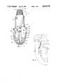
- FIG. 1is a perspective view of a bit of the invention showing the improved gage design
- FIG. 2is a simplified, schematic view of a section of the bit of FIG. 1 showing the profile of the gage section;
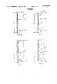
- FIGS. 3-6are simplified schematic views of the prior art gage designs.
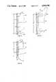
- FIGS. 7-9are simplified schematic views of the gage designs of the invention showing the placement of the cutter elements.
- FIG. 1shows an earth boring bit of the invention designated generally as 11.
- the bit 11includes a body 13 with a threaded shank 15 formed on one end for connection with a drill string member (not shown).
- the body 13also includes a pair of wrench flats 17 which are used to apply the appropriate torque to properly "make-up" the threaded shank 15.
- the body 13has a tubular bore 19 which communicates with the interior of the drill string member, and which communicates by internal fluid passageways (not shown) with one or more fluid openings 21 which are used to circulate fluids to the bit face.
- a bit head or "matrix” 23in a predetermined configuration to include cutting elements 25, longitudinally extending lands 27, 28 and fluid courses or void areas 29.
- the matrix 23is of a composition of the same type used in conventional diamond matrix bits, one example being that which is disclosed in U.S. Pat. No. 3,175,629 to David S. Rowley, issued Mar. 30, 1965.
- Such matricescan be, for example, formed of copper-nickel alloy containing powdered tungsten carbide.
- Matrix head bits of the type under considerationare manufactured by casting the matrix material in a mold about a steel mandrel.
- the moldis first fabricated from graphite stock by turning on a lathe and machining a negative of the desired bit profile.
- Cutter pocketsare then milled in the interior of the mold to the proper contours and dressed to define the position and angle of the cutters.
- the fluid channels and internal fluid passagewaysare formed by positioning a temporary displacement material within the interior of the mold which will later be removed.
- a steel mandrelis then inserted into the interior of the mold and the tungsten carbide powders, binders and flux are added to the mold.
- the steel mandrelacts as a ductile core to which the matrix material adheres during the casting and cooling state.
- the moldis removed and the cutters are mounted on the exterior bit face within recesses in or receiving pockets of the matrix.
- the earth boring bit of FIG. 1has a ballistic or "bullet-shaped" profile which increases in external diameter between the nose 31 and the gage region 33 of the bit.
- the face region of the bitextends generally along the region "X”
- the gage regionextends generally along the region "Y”
- the shankextends generally along the region "Z”.
- the bitis generally conical in cross-section and converges from the gage region "Y" to the nose 31.
- gageis meant the point at which the bit begins to cut the full diameter. That is, for an 81/2 inch diameter bit, this would be the location on the bit face at which the bit would cut an 81/2 inch diameter hole.
- each fluid course 29comprises a groove of lesser relative external diameter located between two selected lands (27, 28 in FIG. 1) on the bit face.
- the lands 27, 28have polycrystalline diamond cutter elements 25 mounted therein within backings of the matrix for drilling the earthen formations.
- the backings 35 for the cutting elements 25are portions of the matrix which protrude outwardly from the face of the bit and which are formed with cutter receiving pockets or recesses during the casting operation.
- the cutting elements 25are of a hard material, preferably polycrystalline diamond composite compacts. Such cutting elements are formed by sintering a polycrystalline diamond layer to a tungsten carbide substrate and are commercially available to the drilling industry from General Electric Company under the "STRATAPAX" trademark. The compact is mounted in the recess provided in the matrix by braising the compact within the recess.
- the preferred cutting elements 25are generally cylindrical.
- each land 27, 28is formed as a convex ridge of the matrix material which extends from the nose 31 outwardly in an arcuate path, the path gradually transitioning to extend generally longitudinally along the bit axis 37 to terminate in a bisected planar pad at the gage region 33 of the bit.
- the bisected planar padincludes an upper stabilizing region 41 adjacent the bit shoulder 43.
- the upper stabilizing region 41has small diamonds (polycrystalline and/or natural) embedded in the surface thereof and has longitudinal troughs which extend generally parallel to the longitudinal axis 37 of the bit.
- upperis meant in the direction of the shank 15 when the bit body is viewed in the drilling position shown in FIG. 1.
- the bisected planar padalso includes a lower stabilizing region 45 of full gage diameter cutter elements, similar to upper region 41.
- the lower region 45is spaced-apart axially on the bit face from the upper stabilizing region 41.
- the upper and lower stabilizing regions 41, 45are separated by an undercut region 47.
- Undercut region 47has a greater relative external diameter than the grooves 29 but a lesser relative external diameter than the bisected pad regions 41, 45.
- the undercut region 47is selectively sized to minimize contact with the borehole wall, thereby maintaining an effective gage length for the bit 13 without increasing the total contact area of the bit face with the wall of the borehole being drilled.
- FIGS. 3-6illustrate the prior art concepts for controlling gage wear and dealing with sticky formations.
- FIG. 3is a schematic view of a cast matrix bit 48 using the standard approach where diamonds 49 are embedded in the matrix to the full API gage diameter. PDC cutters are mounted at the bit "heel" to the full API gage diameter.
- FIG. 4shows a prior art matrix bit 52 of the type used in sticky formations in which flush set diamonds 53 are built undersized to limit wall contact. PDC cutters 55, 57 are mounted at full API gage diameter.
- FIG. 5shows a prior art steel bodied PDC bit 59 utilizing a standard approach in which tungsten carbide compacts 61, 63, 65 are pressed into the bit body to the full API gage diameter.
- a PDC stud 67is pressed in to the bit body to the full API gage diameter
- FIG. 6shows a prior art approach for sticky formations utilizing a steel bodied bit 69.
- Tungsten carbide compacts 71, 73are pressed in undersize to limit wall contact.
- PDC studs 75, 77are pressed in to the bit body to full API gage diameter.
- the effective gage length of the prior art approachis illustrated as "g 3 "-"g 6 ".
- FIGS. 7-9illustrate the novel approach of the invention in which an upper stabilizing region and lower stabilizing region of full gage diameter cutter elements are separated by an intermediate undercut region.
- FIG. 7shows a cast matrix bit 79 having an undercut region 81 which is undersized to limit wall contact and allow clearance for steering of the bit.
- PDC cutters 83, 85are mounted to the full API gage diameter on either side of the undercut region 81.
- the circumferentially spaced cutters 83form an "outrigger" which minimizes contact with the borehole wall 87.
- the undercut region 81is thus spaced-apart from the borehole wall 87 by a diameter "D" which is typically 2 to 3 times greater than the spacing of the prior art approaches.
- FIG. 8shows a natural diamond bit 89 having an upper stabilizing region 91 with natural diamonds 93 embedded therein, a lower stabilizing region 95, and an intermediate undercut region 97.
- the undercut region 97is intentionally undersized to minimize wall contact with the surrounding borehole wall 99.
- the upper and lower regions 91, 95are sized to the full API gage diameter.
- FIG. 9shows a steel bodied PDC bit 101 having PDC studs pressed in to the full gage diameter at the top stabilizing region 103 and the lower stabilizing region 105. The upper and lower regions are separated by an undersized region 107.
- the effective gage lengthis indicated in each of the bits of the invention as “g 7 "-"g 9 ".
- the novel gage design of the inventionprovides an overall gage length which equals or exceeds the gage length of the prior art designs, while at the same time minimizing wall contact with the surrounding borehole. As a result, gage wear is reduced, thereby decreasing the tendency of the bit to "wobble" and prolonging bit life.
- gage wearis reduced, thereby decreasing the tendency of the bit to "wobble" and prolonging bit life.
- bit wobbleis limited and borehole sticking problems are often solved.
- the bit manufacturercan fine-tune the directional drilling characteristics of one-piece bits. In this manner, controlled steering possibilities are provided which were not available in the prior art.
Landscapes
- Engineering & Computer Science (AREA)
- Life Sciences & Earth Sciences (AREA)
- Geology (AREA)
- Mining & Mineral Resources (AREA)
- Mechanical Engineering (AREA)
- Physics & Mathematics (AREA)
- Environmental & Geological Engineering (AREA)
- Fluid Mechanics (AREA)
- General Life Sciences & Earth Sciences (AREA)
- Geochemistry & Mineralogy (AREA)
- Earth Drilling (AREA)
Abstract
Description
Claims (6)
Priority Applications (1)
| Application Number | Priority Date | Filing Date | Title |
|---|---|---|---|
| US07/409,706US4941538A (en) | 1989-09-20 | 1989-09-20 | One-piece drill bit with improved gage design |
Applications Claiming Priority (1)
| Application Number | Priority Date | Filing Date | Title |
|---|---|---|---|
| US07/409,706US4941538A (en) | 1989-09-20 | 1989-09-20 | One-piece drill bit with improved gage design |
Publications (1)
| Publication Number | Publication Date |
|---|---|
| US4941538Atrue US4941538A (en) | 1990-07-17 |
Family
ID=23621655
Family Applications (1)
| Application Number | Title | Priority Date | Filing Date |
|---|---|---|---|
| US07/409,706Expired - LifetimeUS4941538A (en) | 1989-09-20 | 1989-09-20 | One-piece drill bit with improved gage design |
Country Status (1)
| Country | Link |
|---|---|
| US (1) | US4941538A (en) |
Cited By (23)
| Publication number | Priority date | Publication date | Assignee | Title |
|---|---|---|---|---|
| US5178222A (en)* | 1991-07-11 | 1993-01-12 | Baker Hughes Incorporated | Drill bit having enhanced stability |
| US5199511A (en)* | 1991-09-16 | 1993-04-06 | Baker-Hughes, Incorporated | Drill bit and method for reducing formation fluid invasion and for improved drilling in plastic formations |
| EP0569663A1 (en)* | 1992-05-15 | 1993-11-18 | Baker Hughes Incorporated | Improved anti-whirl drill bit |
| US5558170A (en)* | 1992-12-23 | 1996-09-24 | Baroid Technology, Inc. | Method and apparatus for improving drill bit stability |
| EP0676001A4 (en)* | 1992-12-23 | 1997-09-24 | Baroid Technology Inc | Drill bit having chip breaker polycrystalline diamond compact and hard metal insert at gauge surface. |
| WO1999013194A1 (en)* | 1997-09-08 | 1999-03-18 | Baker Hughes Incorporated | Gage pad arrangements for rotary drill bits |
| US6006845A (en)* | 1997-09-08 | 1999-12-28 | Baker Hughes Incorporated | Rotary drill bits for directional drilling employing tandem gage pad arrangement with reaming capability |
| US6112836A (en)* | 1997-09-08 | 2000-09-05 | Baker Hughes Incorporated | Rotary drill bits employing tandem gage pad arrangement |
| US6138780A (en)* | 1997-09-08 | 2000-10-31 | Baker Hughes Incorporated | Drag bit with steel shank and tandem gage pads |
| US6173797B1 (en) | 1997-09-08 | 2001-01-16 | Baker Hughes Incorporated | Rotary drill bits for directional drilling employing movable cutters and tandem gage pad arrangement with active cutting elements and having up-drill capability |
| BE1012751A5 (en)* | 1997-09-08 | 2001-03-06 | Baker Hughes Inc | Blades rotary drill dirigeable aggression a longitudinal variable size front zone. |
| US6290007B2 (en) | 1997-09-08 | 2001-09-18 | Baker Hughes Incorporated | Rotary drill bits for directional drilling employing tandem gage pad arrangement with cutting elements and up-drill capability |
| EP0869256A3 (en)* | 1997-04-02 | 2002-04-17 | Baker Hughes Incorporated | Rotary drill bit with gage definition region, method of manufacturing such a drill bit and method of drilling a subterranean formation |
| EP1227214A3 (en)* | 2001-01-27 | 2003-03-19 | Camco International (UK) Limited | Cutting structure for drill bit |
| US6810972B2 (en) | 2002-02-08 | 2004-11-02 | Hard Rock Drilling & Fabrication, L.L.C. | Steerable horizontal subterranean drill bit having a one bolt attachment system |
| US6810973B2 (en) | 2002-02-08 | 2004-11-02 | Hard Rock Drilling & Fabrication, L.L.C. | Steerable horizontal subterranean drill bit having offset cutting tooth paths |
| US6810971B1 (en) | 2002-02-08 | 2004-11-02 | Hard Rock Drilling & Fabrication, L.L.C. | Steerable horizontal subterranean drill bit |
| US6814168B2 (en) | 2002-02-08 | 2004-11-09 | Hard Rock Drilling & Fabrication, L.L.C. | Steerable horizontal subterranean drill bit having elevated wear protector receptacles |
| US6827159B2 (en) | 2002-02-08 | 2004-12-07 | Hard Rock Drilling & Fabrication, L.L.C. | Steerable horizontal subterranean drill bit having an offset drilling fluid seal |
| US20070272446A1 (en)* | 2006-05-08 | 2007-11-29 | Varel International Ind. L.P. | Drill bit with application specific side cutting efficiencies |
| US20090321139A1 (en)* | 2007-02-02 | 2009-12-31 | Strachan Michael J | Rotary Drill Bit Steerable System and Method |
| US20130248255A1 (en)* | 2010-12-01 | 2013-09-26 | Vermeer Manufacturing Company | Hard facing configuration for a drilling tool |
| US20130292186A1 (en)* | 2012-05-03 | 2013-11-07 | Smith International, Inc. | Gage cutter protection for drilling bits |
Citations (6)
| Publication number | Priority date | Publication date | Assignee | Title |
|---|---|---|---|---|
| US4140189A (en)* | 1977-06-06 | 1979-02-20 | Smith International, Inc. | Rock bit with diamond reamer to maintain gage |
| US4246977A (en)* | 1979-04-09 | 1981-01-27 | Smith International, Inc. | Diamond studded insert drag bit with strategically located hydraulic passages for mud motors |
| US4545441A (en)* | 1981-02-25 | 1985-10-08 | Williamson Kirk E | Drill bits with polycrystalline diamond cutting elements mounted on serrated supports pressed in drill head |
| US4640375A (en)* | 1982-11-22 | 1987-02-03 | Nl Industries, Inc. | Drill bit and cutter therefor |
| US4696354A (en)* | 1986-06-30 | 1987-09-29 | Hughes Tool Company - Usa | Drilling bit with full release void areas |
| GB2190412A (en)* | 1986-05-16 | 1987-11-18 | Nl Petroleum Prod | Improvements in or relating to rotary drill bits |
- 1989
- 1989-09-20USUS07/409,706patent/US4941538A/ennot_activeExpired - Lifetime
Patent Citations (6)
| Publication number | Priority date | Publication date | Assignee | Title |
|---|---|---|---|---|
| US4140189A (en)* | 1977-06-06 | 1979-02-20 | Smith International, Inc. | Rock bit with diamond reamer to maintain gage |
| US4246977A (en)* | 1979-04-09 | 1981-01-27 | Smith International, Inc. | Diamond studded insert drag bit with strategically located hydraulic passages for mud motors |
| US4545441A (en)* | 1981-02-25 | 1985-10-08 | Williamson Kirk E | Drill bits with polycrystalline diamond cutting elements mounted on serrated supports pressed in drill head |
| US4640375A (en)* | 1982-11-22 | 1987-02-03 | Nl Industries, Inc. | Drill bit and cutter therefor |
| GB2190412A (en)* | 1986-05-16 | 1987-11-18 | Nl Petroleum Prod | Improvements in or relating to rotary drill bits |
| US4696354A (en)* | 1986-06-30 | 1987-09-29 | Hughes Tool Company - Usa | Drilling bit with full release void areas |
Cited By (28)
| Publication number | Priority date | Publication date | Assignee | Title |
|---|---|---|---|---|
| US5178222A (en)* | 1991-07-11 | 1993-01-12 | Baker Hughes Incorporated | Drill bit having enhanced stability |
| US5199511A (en)* | 1991-09-16 | 1993-04-06 | Baker-Hughes, Incorporated | Drill bit and method for reducing formation fluid invasion and for improved drilling in plastic formations |
| EP0569663A1 (en)* | 1992-05-15 | 1993-11-18 | Baker Hughes Incorporated | Improved anti-whirl drill bit |
| US5558170A (en)* | 1992-12-23 | 1996-09-24 | Baroid Technology, Inc. | Method and apparatus for improving drill bit stability |
| EP0676001A4 (en)* | 1992-12-23 | 1997-09-24 | Baroid Technology Inc | Drill bit having chip breaker polycrystalline diamond compact and hard metal insert at gauge surface. |
| EP0869256A3 (en)* | 1997-04-02 | 2002-04-17 | Baker Hughes Incorporated | Rotary drill bit with gage definition region, method of manufacturing such a drill bit and method of drilling a subterranean formation |
| US6006845A (en)* | 1997-09-08 | 1999-12-28 | Baker Hughes Incorporated | Rotary drill bits for directional drilling employing tandem gage pad arrangement with reaming capability |
| US6112836A (en)* | 1997-09-08 | 2000-09-05 | Baker Hughes Incorporated | Rotary drill bits employing tandem gage pad arrangement |
| US6138780A (en)* | 1997-09-08 | 2000-10-31 | Baker Hughes Incorporated | Drag bit with steel shank and tandem gage pads |
| US6173797B1 (en) | 1997-09-08 | 2001-01-16 | Baker Hughes Incorporated | Rotary drill bits for directional drilling employing movable cutters and tandem gage pad arrangement with active cutting elements and having up-drill capability |
| BE1012751A5 (en)* | 1997-09-08 | 2001-03-06 | Baker Hughes Inc | Blades rotary drill dirigeable aggression a longitudinal variable size front zone. |
| US6290007B2 (en) | 1997-09-08 | 2001-09-18 | Baker Hughes Incorporated | Rotary drill bits for directional drilling employing tandem gage pad arrangement with cutting elements and up-drill capability |
| US6321862B1 (en) | 1997-09-08 | 2001-11-27 | Baker Hughes Incorporated | Rotary drill bits for directional drilling employing tandem gage pad arrangement with cutting elements and up-drill capability |
| WO1999013194A1 (en)* | 1997-09-08 | 1999-03-18 | Baker Hughes Incorporated | Gage pad arrangements for rotary drill bits |
| EP1227214A3 (en)* | 2001-01-27 | 2003-03-19 | Camco International (UK) Limited | Cutting structure for drill bit |
| US6810972B2 (en) | 2002-02-08 | 2004-11-02 | Hard Rock Drilling & Fabrication, L.L.C. | Steerable horizontal subterranean drill bit having a one bolt attachment system |
| US6810973B2 (en) | 2002-02-08 | 2004-11-02 | Hard Rock Drilling & Fabrication, L.L.C. | Steerable horizontal subterranean drill bit having offset cutting tooth paths |
| US6810971B1 (en) | 2002-02-08 | 2004-11-02 | Hard Rock Drilling & Fabrication, L.L.C. | Steerable horizontal subterranean drill bit |
| US6814168B2 (en) | 2002-02-08 | 2004-11-09 | Hard Rock Drilling & Fabrication, L.L.C. | Steerable horizontal subterranean drill bit having elevated wear protector receptacles |
| US6827159B2 (en) | 2002-02-08 | 2004-12-07 | Hard Rock Drilling & Fabrication, L.L.C. | Steerable horizontal subterranean drill bit having an offset drilling fluid seal |
| US20070272446A1 (en)* | 2006-05-08 | 2007-11-29 | Varel International Ind. L.P. | Drill bit with application specific side cutting efficiencies |
| US20090321139A1 (en)* | 2007-02-02 | 2009-12-31 | Strachan Michael J | Rotary Drill Bit Steerable System and Method |
| US8172010B2 (en)* | 2007-02-02 | 2012-05-08 | Halliburton Energy Services, Inc. | Rotary drill bit steerable system and method |
| US20130248255A1 (en)* | 2010-12-01 | 2013-09-26 | Vermeer Manufacturing Company | Hard facing configuration for a drilling tool |
| AU2011336626B2 (en)* | 2010-12-01 | 2017-01-12 | Vermeer Manufacturing Company | Hardfacing configuration for a drilling tool |
| US9624730B2 (en)* | 2010-12-01 | 2017-04-18 | Vermeer Manufacturing Company | Hard facing configuration for a drilling tool |
| US20130292186A1 (en)* | 2012-05-03 | 2013-11-07 | Smith International, Inc. | Gage cutter protection for drilling bits |
| US9464490B2 (en)* | 2012-05-03 | 2016-10-11 | Smith International, Inc. | Gage cutter protection for drilling bits |
Similar Documents
| Publication | Publication Date | Title |
|---|---|---|
| US4941538A (en) | One-piece drill bit with improved gage design | |
| US4696354A (en) | Drilling bit with full release void areas | |
| US5033560A (en) | Drill bit with decreasing diameter cutters | |
| US5056382A (en) | Matrix diamond drag bit with PCD cylindrical cutters | |
| US6068072A (en) | Cutting element | |
| US5007493A (en) | Drill bit having improved cutting element retention system | |
| US4714120A (en) | Diamond drill bit with co-joined cutters | |
| CA1214159A (en) | Drill bit and improved cutting element | |
| US4792001A (en) | Rotary drill bit | |
| CA2505710C (en) | Shaped cutter surface | |
| US8752654B2 (en) | Drill bits with bearing elements for reducing exposure of cutters | |
| US4574895A (en) | Solid head bit with tungsten carbide central core | |
| US5979577A (en) | Stabilizing drill bit with improved cutting elements | |
| US7798257B2 (en) | Shaped cutter surface | |
| US7070011B2 (en) | Steel body rotary drill bits including support elements affixed to the bit body at least partially defining cutter pocket recesses | |
| US5163524A (en) | Rotary drill bits | |
| EP2129860B1 (en) | Method of forming pockets for receiving drill bit cutting elements | |
| US4942933A (en) | Relating to rotary drill bits | |
| US20150047913A1 (en) | Cutters for fixed cutter bits | |
| US6021858A (en) | Drill bit having trapezium-shaped blades | |
| US4911254A (en) | Polycrystalline diamond cutting element with mating recess | |
| US20100122851A1 (en) | Ultra-hard drilling stabilizer | |
| US6575256B1 (en) | Drill bit with lateral movement mitigation and method of subterranean drilling | |
| US5383527A (en) | Asymmetrical PDC cutter | |
| US6193000B1 (en) | Drag-type rotary drill bit |
Legal Events
| Date | Code | Title | Description |
|---|---|---|---|
| AS | Assignment | Owner name:HUGHES TOOL COMPANY, TEXAS Free format text:ASSIGNMENT OF ASSIGNORS INTEREST.;ASSIGNOR:KING, WILLIAM W.;REEL/FRAME:005153/0365 Effective date:19890914 | |
| STCF | Information on status: patent grant | Free format text:PATENTED CASE | |
| AS | Assignment | Owner name:DRESSER INDUSTRIES, INC., TEXAS Free format text:ASSIGNMENT OF ASSIGNORS INTEREST.;ASSIGNOR:HUGHES TOOL COMPANY;REEL/FRAME:005452/0701 Effective date:19900620 | |
| AS | Assignment | Owner name:DRESSER INDUSTRIES, INC., A CORP. OF DE, TEXAS Free format text:ASSIGNMENT OF ASSIGNORS INTEREST.;ASSIGNOR:HUGHES TOOL COMPANY, A CORP. OF DE;REEL/FRAME:005485/0074 Effective date:19901009 | |
| FEPP | Fee payment procedure | Free format text:PAYOR NUMBER ASSIGNED (ORIGINAL EVENT CODE: ASPN); ENTITY STATUS OF PATENT OWNER: LARGE ENTITY | |
| FPAY | Fee payment | Year of fee payment:4 | |
| FEPP | Fee payment procedure | Free format text:PAYER NUMBER DE-ASSIGNED (ORIGINAL EVENT CODE: RMPN); ENTITY STATUS OF PATENT OWNER: LARGE ENTITY Free format text:PAYOR NUMBER ASSIGNED (ORIGINAL EVENT CODE: ASPN); ENTITY STATUS OF PATENT OWNER: LARGE ENTITY | |
| FPAY | Fee payment | Year of fee payment:8 | |
| FPAY | Fee payment | Year of fee payment:12 | |
| AS | Assignment | Owner name:HALLIBURTON ENERGY SERVICES, INC., TEXAS Free format text:ASSIGNMENT OF ASSIGNORS INTEREST;ASSIGNOR:DRESSER INDUSTRIES, INC. (NOW KNOWN AS DII INDUSTRIES, LLC);REEL/FRAME:013727/0291 Effective date:20030113 |