US4941532A - Anchor device - Google Patents
Anchor deviceDownload PDFInfo
- Publication number
- US4941532A US4941532AUS07/331,290US33129089AUS4941532AUS 4941532 AUS4941532 AUS 4941532AUS 33129089 AUS33129089 AUS 33129089AUS 4941532 AUS4941532 AUS 4941532A
- Authority
- US
- United States
- Prior art keywords
- arm
- expander
- wall
- supporting member
- well bore
- Prior art date
- Legal status (The legal status is an assumption and is not a legal conclusion. Google has not performed a legal analysis and makes no representation as to the accuracy of the status listed.)
- Expired - Lifetime
Links
Images

Classifications
- E—FIXED CONSTRUCTIONS
- E21—EARTH OR ROCK DRILLING; MINING
- E21B—EARTH OR ROCK DRILLING; OBTAINING OIL, GAS, WATER, SOLUBLE OR MELTABLE MATERIALS OR A SLURRY OF MINERALS FROM WELLS
- E21B23/00—Apparatus for displacing, setting, locking, releasing or removing tools, packers or the like in boreholes or wells
- E21B23/01—Apparatus for displacing, setting, locking, releasing or removing tools, packers or the like in boreholes or wells for anchoring the tools or the like
Definitions
- This inventionrelates to anchor devices for well tools and/or well strings in well bores traversing earth formations, and more particularly, to mechanical slip anchor devices which are collapsible to a diametrical size adaptable for passage through a restricted bore diameter in a well bore and which are subsequently expandable in a larger diameter bore to an anchoring condition.
- Anchor devices for well tools and well stringsare commonly used to releasably attach well tools and equipment to a well casing or well pipe where the well pipe is a tubular metal member and traverses earth formations.
- An anchor devicecan be utilized with a variety of well tool devices, for example with a rod pump, or can be incorporated in a tool such as a bridge plug or packer. Irrespective of the application, the anchor device must be passed in a retracted condition through the bore of the casing or pipe to a location where setting of the anchor is intended. Setting of the anchor device involves extending gripping members radially outward from the device into gripping contact with the bore of the casing or the pipe.
- the anchor devicecan be subsequently released and moved to a retracted condition for retrieval.
- the anchor devicecan be disabled by actuating a shear means so that the gripping members retract and the anchor device can be retrieved.
- the slipsare elongated members disposed circumferentially around an annular bowl member an "expander") which has an inclined or wedging surface.
- the inclined surface on an expanderare movable relative to inclined surfaces on the slips and are cooperable to move the slips radially outward where serrated outer surfaces on the slips grip the casing.
- the wedging action of the inclined surfacesmaintains the grip of the slips with respect to a casing.
- a well borecan contain a 31/2 inch I.D. bore adjacent to a lower 5 inch I.D. bore.
- the anchor devicemust traverse through a 31/2 inch bore and expand to a 5 inch bore.
- any practical mechanical slip anchor devices utilizing slipswhich can pass through a restricted bore and subsequently be moved radially a substantial distance for gripping engagement with a casing and which can be subsequently retracted and retrieved.
- the anchor deviceis adapted for coupling to the lower end of a tubing string or a well tool.
- the anchor deviceincludes a longitudinally extending, tubular central supporting mandrel.
- At the lower end of the supporting mandrelis an elongated expander member which has lengthwise extending first and second adjacent and inclined expander surfaces.
- Above the expander memberis a tubular arm support on the supporting mandrel.
- the arm supportpivotally supports downwardly extending and elongated arm members which are circumferentially arranged about the central axis of the supporting mandrel.
- At the lower and inwardly facing end of each arm memberare longitudinally extending first and second adjacent and inclined arm surfaces.
- each arm memberhas a recess which receives an external gripping member.
- the first inclined arm surfaces and the first expander surfacehave a complementary angle of 45° with respect to the central axis of the supporting mandrel in a retracted condition.
- the second inclined arm surfaces and the second expander surfacehave a complementary angle of 5° with respect to the central axis of the supporting mandrel when the second surfaces are engaged in an extended condition.
- the first surfacesare brought into engagement and the 45° angle produces a substantial radial outward movement of the lower ends of the arm member while the upper ends of the arm members the pivot in the arm support.
- the angle of inclinationis steep so that the engaged inclined surfaces can move the wall engaging members into gripping engagement with the casing.
- the anchor deviceis provided with an emergency release which is responsive to rotation of the central supporting mandrel to threadedly uncouple a coupling nut and to a shear pin release of the central supporting mandrel from the expander member.
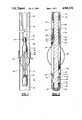
- FIG. 1is longitudinal view in partial cross section of a well tool embodying the present invention and disposed in a well bore;
- FIG. 2is a longitudinal view in cross section of a well anchor device embodying the present invention
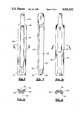
- FIG. 3is a side view of the arm support member
- FIG. 4is a bottom view of the arm support member
- FIG. 5is a partial view in partial cross section of the cooperating end of an arm member and the expander member
- FIG. 6is a view similar to FIG. 5 showing further relocation of the arm member relative to the expander member;
- FIG. 7is a view similar to FIG. 6 showing further relocation of the outer member relative to the expander member
- FIG. 8is a top view of an arm member
- FIG. 9is a side view of an arm member
- FIG. 10is a bottom view of an arm member
- FIG. 11is a view taken along line 11--11 of FIG. 8;
- FIG. 12is a view taken along line 12--12 of FIG. 10.
- a tubular metal casing 20traverses earth formation 21.
- a tubular member 22which has a bore diameter substantially less than the bore diameter of the casing 21.
- a smaller diameter tubing string 24is shown with an attached tubing anchor device 26.
- the tubing anchor device 26has a central supporting mandrel 30.
- the supporting mandrel 30has an upper connection portion 31 with a reduced diameter recess 32 which is attachable by attaching means 34 to the lower end of the tubing string 24.
- On the supporting mandrel 30is a tubular release housing member 36, a tubular coupling housing member and a tubular arm support member 40.
- the arm support memberhas two sets 42 and 44 of three arm members each.
- the sets 42, 44 of arm membersare angularly disposed about the circumference of the arm support member and arranged so that an arm of set 42 is disposed between an adjacent pair of arms of set 44 and so that an arm of set 44 is disposed between an adjacent pair of arms of set 42.
- One of the sets 44 of armshas overlaid spring members 48.
- the one end of a spring member 48is attached to an arm 44a (see FIG. 2) while the opposite end of the spring member is free to slide along the outer surface of an arm.
- the spring members 48are made of resilient spring material and bowed outwardly to frictionally engage the wall of a casing 20 in a well known manner. As may be appreciated the spring members 48 are compressed against the arm members of set 42 when passing through a restricted bore such as the pipe 22.
- each arm memberAt the lower end of each arm member and in the outer wall of each arm member is a recess 51 which receives a rectangularly shaped and elongated wall engaging member 52.
- a well engaging member 52is pivotally mounted by a pivot pin in a recess 51 and has an outer serrated surface for engagement with a casing.
- the lower end of each arm memberis disposed in a retracted condition adjacent to the central supporting mandrel and to an expander member 56.
- the expander member 56is coupled to the central supporting mandrel 30.
- the central supporting mandrel 30is a cylindrically shaped member which has its lower end threadedly attached at 60 to an end cap member 62.
- a locking pin 64 in the cap member 62engages an annular groove in the supporting member 30 rotatively couples the supporting mandrel 30 to the end cap member 62.
- the end cap member 62is disposed in the hollow interior of the expander member 56 and coupled by a shear pin 66 to the expander member 56.
- the shear pin 66is for an emergency release and when the shear pin 66 is released by shearing, relative movement of the supporting mandrel is permitted relative to the expander member 56.
- the supporting mandrel 30has a vertical or longitudinally extending slot 68 which slidably receives a pin 70 in the expander member 56.
- the pin and slotprevent relative rotation and permit relative longitudinal movement.
- the pin 70also limits upward movement of the expander member 56 relative to the supporting mandrel and limits downward movement of the expander member relative to the supporting mandrel.
- the supporting mandrel 30has a flange 72 which is rotatively disposed between bearing plates in an annular recess in the housing member 36.
- the lower end of the housing member 36has an internal left hand thread 74 which threadedly engage an external thread on coupling member 38.
- the housing member 36In the recess between the upper end of the coupling member 38 and the internal bore in the housing member 36, the housing member 36 has a downwardly extending pin 76 while the coupling 38 has an upwardly extending pin 78.
- the ends of the pins 76 and 78are arranged and located so that from a position of engagement one relative rotation of the housing member 36 in a left-hand or counterclockwise direction will cause the ends of the pins to clear one another and permit the threaded uncoupling of the coupling member 38. Engagement of the pins 76, 78 on right-hand rotation prevents thread damage. Rotation of the tubing string 24 thus can move the coupling member 38 downwardly relative to the housing member 36.
- the coupling member 38is co-rotatively coupled to the supporting mandrel 30 by a pin 80 in the coupling member which is slidably received in a longitudinal groove in the supporting mandrel 30.
- the arm support member 40is a tubular member which has at its upper end a reduced diameter section 79 which is arranged to be slidably received in a counter bore of the coupling member 38.
- the coupling member 38has longitudinal slots 81 which cooperate which a pin 82 in the support member. The slots 81 and pins 82 provide a lost motion connection to enable release of the shear pin 66.
- first set of longitudinal grooves 84which extend upwardly from an end surface 85.
- a second set of longitudinal grooves 86extends upwardly from the end surface 85 and are offset angularly from the grooves 84 by an angle of 60°.
- the grooves 86are deeper or longer than the grooves 84.
- the vertical or longitudinal offset of the grooves 84, 86accommodates different lengths of arm members in the sets 42 and 44 and permits location of the pivot connections 90, 92 (shown as axis in FIG. 4) in the support member 40.
- the length of the membersis 121/2 inches and 131/2 inches for a 31/2 inch diameter tool which permits the pivoting outward movement of the wall engaging ends of the arm members to a 5 inch internal diameter.
- the arm membersare substantially identical except that one set is longer than the other set and only one set carries the bow springs.
- a typical arm member 44ais illustrated in FIGS. 8-12 wherein the arm member has a cross section (FIG. 11, 12) which is a wall segment of tubular member with inner and outer curved wall surfaces 96, 98 and side wall surfaces 100, 102 that are angularly related.
- a wall surface 100for example, if extended inwardly would intersect the longitudinal axis of the support member 30 and the curvature of the surfaces 96 would be complementary to the curvature of the supporting member 30.
- the arm member 44ahas a lengthwise extending groove 104 which receives a spring member 48.
- a threaded bore 106is provided for attaching one end of a spring member to an arm member.
- One end 108 of the arm memberis shaped to be received in a slot in the arm support member 40.
- the recess 51is "T" shaped in cross section and a wall engaging member is pivotally mounted in a recess.
- the lower end of an armhas a tapered or inclined surface 108, 110 with respect to each of the lengthwise extending surfaces 96, 98.
- the angle of inclination of the surfaces 108, 110is 5° relative to a lengthwise extending plane defined by the bottom surface of the groove 104.
- the arm member 44ais another second inclined surface 112 is adjacent to and adjoining the first surface 108 on the arm member.
- the surface 112has an angle of inclination of 45° relative to the lengthwise extending plane defined by the bottom surface of the groove 104.
- the surfaces 108, 110are inclined at an angle of 5° relative to the longitudinal axis of the supporting member 30 while the surface 112 is at an angle of 45° relative to the longitudinal axis of the supporting member 30 and to a transverse axis.
- the expander memberhas a first annular and inclined surface 113 at an angle of 45° with respect to the longitudinal axis for the support member 30 and an adjacent and adjoining surface 114 which is at an angle of inclination of 5° relative to the central axis of the support member 30.
- the toolIn the operation and functioning of the tool, it is attached to a string of pipe and lowered in a collapsed condition (shown in FIG. 2) to a location where anchoring is desired.
- the spring members 48are in frictional engagement with the wall of a well casing. At the desired location, the tubing string is rotated in a left-hand or counterclockwise direction.
- the spring members 48are attached to the arm members which are attached to the arm support member which is, in turn coupled to the member 38 so that rotation of the housing member 36 unscrews the threaded connection at 74 and moves the member 38 downwardly.
- the arm inclination surfaces 112engage the expander inclination surface 113 (see FIG.
Landscapes
- Life Sciences & Earth Sciences (AREA)
- Engineering & Computer Science (AREA)
- Geology (AREA)
- Mining & Mineral Resources (AREA)
- Physics & Mathematics (AREA)
- Environmental & Geological Engineering (AREA)
- Fluid Mechanics (AREA)
- General Life Sciences & Earth Sciences (AREA)
- Geochemistry & Mineralogy (AREA)
- Piles And Underground Anchors (AREA)
Abstract
Description
Claims (11)
Priority Applications (1)
| Application Number | Priority Date | Filing Date | Title |
|---|---|---|---|
| US07/331,290US4941532A (en) | 1989-03-31 | 1989-03-31 | Anchor device |
Applications Claiming Priority (1)
| Application Number | Priority Date | Filing Date | Title |
|---|---|---|---|
| US07/331,290US4941532A (en) | 1989-03-31 | 1989-03-31 | Anchor device |
Publications (1)
| Publication Number | Publication Date |
|---|---|
| US4941532Atrue US4941532A (en) | 1990-07-17 |
Family
ID=23293345
Family Applications (1)
| Application Number | Title | Priority Date | Filing Date |
|---|---|---|---|
| US07/331,290Expired - LifetimeUS4941532A (en) | 1989-03-31 | 1989-03-31 | Anchor device |
Country Status (1)
| Country | Link |
|---|---|
| US (1) | US4941532A (en) |
Cited By (72)
| Publication number | Priority date | Publication date | Assignee | Title |
|---|---|---|---|---|
| EP0699818A3 (en)* | 1994-08-31 | 1998-05-27 | Halliburton Company | Downhole tool hanger |
| US6470966B2 (en) | 1998-12-07 | 2002-10-29 | Robert Lance Cook | Apparatus for forming wellbore casing |
| US6557640B1 (en) | 1998-12-07 | 2003-05-06 | Shell Oil Company | Lubrication and self-cleaning system for expansion mandrel |
| US6568471B1 (en) | 1999-02-26 | 2003-05-27 | Shell Oil Company | Liner hanger |
| US6575240B1 (en) | 1998-12-07 | 2003-06-10 | Shell Oil Company | System and method for driving pipe |
| US6575250B1 (en) | 1999-11-15 | 2003-06-10 | Shell Oil Company | Expanding a tubular element in a wellbore |
| US6634431B2 (en) | 1998-11-16 | 2003-10-21 | Robert Lance Cook | Isolation of subterranean zones |
| US6640903B1 (en) | 1998-12-07 | 2003-11-04 | Shell Oil Company | Forming a wellbore casing while simultaneously drilling a wellbore |
| US6712154B2 (en) | 1998-11-16 | 2004-03-30 | Enventure Global Technology | Isolation of subterranean zones |
| US6725919B2 (en) | 1998-12-07 | 2004-04-27 | Shell Oil Company | Forming a wellbore casing while simultaneously drilling a wellbore |
| US6745845B2 (en) | 1998-11-16 | 2004-06-08 | Shell Oil Company | Isolation of subterranean zones |
| US6823937B1 (en) | 1998-12-07 | 2004-11-30 | Shell Oil Company | Wellhead |
| US6892819B2 (en) | 1998-12-07 | 2005-05-17 | Shell Oil Company | Forming a wellbore casing while simultaneously drilling a wellbore |
| US6968618B2 (en) | 1999-04-26 | 2005-11-29 | Shell Oil Company | Expandable connector |
| US6976541B2 (en) | 2000-09-18 | 2005-12-20 | Shell Oil Company | Liner hanger with sliding sleeve valve |
| US7011161B2 (en) | 1998-12-07 | 2006-03-14 | Shell Oil Company | Structural support |
| US7048067B1 (en) | 1999-11-01 | 2006-05-23 | Shell Oil Company | Wellbore casing repair |
| US7055608B2 (en) | 1999-03-11 | 2006-06-06 | Shell Oil Company | Forming a wellbore casing while simultaneously drilling a wellbore |
| US7100685B2 (en) | 2000-10-02 | 2006-09-05 | Enventure Global Technology | Mono-diameter wellbore casing |
| US7100684B2 (en) | 2000-07-28 | 2006-09-05 | Enventure Global Technology | Liner hanger with standoffs |
| US7121352B2 (en) | 1998-11-16 | 2006-10-17 | Enventure Global Technology | Isolation of subterranean zones |
| US7168496B2 (en) | 2001-07-06 | 2007-01-30 | Eventure Global Technology | Liner hanger |
| US7168499B2 (en) | 1998-11-16 | 2007-01-30 | Shell Oil Company | Radial expansion of tubular members |
| US7172024B2 (en) | 2000-10-02 | 2007-02-06 | Shell Oil Company | Mono-diameter wellbore casing |
| US7195064B2 (en) | 1998-12-07 | 2007-03-27 | Enventure Global Technology | Mono-diameter wellbore casing |
| US7231985B2 (en) | 1998-11-16 | 2007-06-19 | Shell Oil Company | Radial expansion of tubular members |
| US7234531B2 (en) | 1999-12-03 | 2007-06-26 | Enventure Global Technology, Llc | Mono-diameter wellbore casing |
| US7258168B2 (en) | 2001-07-27 | 2007-08-21 | Enventure Global Technology L.L.C. | Liner hanger with slip joint sealing members and method of use |
| US20070204987A1 (en)* | 2006-03-06 | 2007-09-06 | Gustavo Ignacio Carro | Anchoring device for casing procedures in wellbores |
| US7290605B2 (en) | 2001-12-27 | 2007-11-06 | Enventure Global Technology | Seal receptacle using expandable liner hanger |
| US7290616B2 (en) | 2001-07-06 | 2007-11-06 | Enventure Global Technology, L.L.C. | Liner hanger |
| US7308755B2 (en) | 2003-06-13 | 2007-12-18 | Shell Oil Company | Apparatus for forming a mono-diameter wellbore casing |
| US7325602B2 (en) | 2000-10-02 | 2008-02-05 | Shell Oil Company | Method and apparatus for forming a mono-diameter wellbore casing |
| US7350563B2 (en) | 1999-07-09 | 2008-04-01 | Enventure Global Technology, L.L.C. | System for lining a wellbore casing |
| US7350564B2 (en) | 1998-12-07 | 2008-04-01 | Enventure Global Technology, L.L.C. | Mono-diameter wellbore casing |
| US7360591B2 (en) | 2002-05-29 | 2008-04-22 | Enventure Global Technology, Llc | System for radially expanding a tubular member |
| US7363984B2 (en) | 1998-12-07 | 2008-04-29 | Enventure Global Technology, Llc | System for radially expanding a tubular member |
| US7377326B2 (en) | 2002-08-23 | 2008-05-27 | Enventure Global Technology, L.L.C. | Magnetic impulse applied sleeve method of forming a wellbore casing |
| US7383889B2 (en) | 2001-11-12 | 2008-06-10 | Enventure Global Technology, Llc | Mono diameter wellbore casing |
| US7398832B2 (en) | 2002-06-10 | 2008-07-15 | Enventure Global Technology, Llc | Mono-diameter wellbore casing |
| US7404444B2 (en) | 2002-09-20 | 2008-07-29 | Enventure Global Technology | Protective sleeve for expandable tubulars |
| US7410000B2 (en) | 2001-01-17 | 2008-08-12 | Enventure Global Technology, Llc. | Mono-diameter wellbore casing |
| US7416027B2 (en) | 2001-09-07 | 2008-08-26 | Enventure Global Technology, Llc | Adjustable expansion cone assembly |
| US7424918B2 (en) | 2002-08-23 | 2008-09-16 | Enventure Global Technology, L.L.C. | Interposed joint sealing layer method of forming a wellbore casing |
| US7438133B2 (en) | 2003-02-26 | 2008-10-21 | Enventure Global Technology, Llc | Apparatus and method for radially expanding and plastically deforming a tubular member |
| US7503393B2 (en) | 2003-01-27 | 2009-03-17 | Enventure Global Technology, Inc. | Lubrication system for radially expanding tubular members |
| US20090071660A1 (en)* | 2007-09-19 | 2009-03-19 | Ruben Martinez | Low Stress Traction System |
| WO2009037657A1 (en) | 2007-09-18 | 2009-03-26 | Schlumberger Canada Limited | Anchoring system for use in a wellbore |
| US7513313B2 (en) | 2002-09-20 | 2009-04-07 | Enventure Global Technology, Llc | Bottom plug for forming a mono diameter wellbore casing |
| US7516790B2 (en) | 1999-12-03 | 2009-04-14 | Enventure Global Technology, Llc | Mono-diameter wellbore casing |
| US7552776B2 (en) | 1998-12-07 | 2009-06-30 | Enventure Global Technology, Llc | Anchor hangers |
| US7571774B2 (en) | 2002-09-20 | 2009-08-11 | Eventure Global Technology | Self-lubricating expansion mandrel for expandable tubular |
| US7603758B2 (en) | 1998-12-07 | 2009-10-20 | Shell Oil Company | Method of coupling a tubular member |
| US20100101865A1 (en)* | 2007-03-30 | 2010-04-29 | Datc Europe | Device for protecting a geotechnical or geophysical probe |
| US7712522B2 (en) | 2003-09-05 | 2010-05-11 | Enventure Global Technology, Llc | Expansion cone and system |
| US7740076B2 (en) | 2002-04-12 | 2010-06-22 | Enventure Global Technology, L.L.C. | Protective sleeve for threaded connections for expandable liner hanger |
| US7739917B2 (en) | 2002-09-20 | 2010-06-22 | Enventure Global Technology, Llc | Pipe formability evaluation for expandable tubulars |
| US7775290B2 (en) | 2003-04-17 | 2010-08-17 | Enventure Global Technology, Llc | Apparatus for radially expanding and plastically deforming a tubular member |
| US7793721B2 (en) | 2003-03-11 | 2010-09-14 | Eventure Global Technology, Llc | Apparatus for radially expanding and plastically deforming a tubular member |
| US7819185B2 (en) | 2004-08-13 | 2010-10-26 | Enventure Global Technology, Llc | Expandable tubular |
| US7886831B2 (en) | 2003-01-22 | 2011-02-15 | Enventure Global Technology, L.L.C. | Apparatus for radially expanding and plastically deforming a tubular member |
| US7918284B2 (en) | 2002-04-15 | 2011-04-05 | Enventure Global Technology, L.L.C. | Protective sleeve for threaded connections for expandable liner hanger |
| CN102482934A (en)* | 2009-08-28 | 2012-05-30 | 国际壳牌研究有限公司 | System and method for anchoring an expandable tubular to a borehole wall |
| CN102482933A (en)* | 2009-08-28 | 2012-05-30 | 国际壳牌研究有限公司 | System and method for anchoring an expandable tubular to a borehole wall |
| EP2835492A3 (en)* | 2013-08-01 | 2016-01-06 | Weatherford/Lamb Inc. | Insert units for non-metallic slips |
| US20160290081A1 (en)* | 2013-12-20 | 2016-10-06 | Halliburton Energy Services, Inc. | High Radial Expansion Anchoring Tool |
| US9677356B2 (en) | 2012-10-01 | 2017-06-13 | Weatherford Technology Holdings, Llc | Insert units for non-metallic slips oriented normal to cone face |
| US9725981B2 (en) | 2012-10-01 | 2017-08-08 | Weatherford Technology Holdings, Llc | Non-metallic slips having inserts oriented normal to cone face |
| US20190284894A1 (en)* | 2018-03-16 | 2019-09-19 | Weatherford Technology Holdings, Llc | Downhole casing pulling tool |
| CN111854199A (en)* | 2020-07-30 | 2020-10-30 | 葛佳文 | Open type drilling wall device of middle-deep geothermal heat exchange well |
| US11248427B2 (en) | 2018-08-06 | 2022-02-15 | Schlumberger Technology Corporation | Systems and methods for manipulating wellbore completion products |
| US20240353810A1 (en)* | 2020-05-02 | 2024-10-24 | Schlumberger Technology Corporation | Normalized shifting visualizer |
Citations (5)
| Publication number | Priority date | Publication date | Assignee | Title |
|---|---|---|---|---|
| US1074427A (en)* | 1912-01-24 | 1913-09-30 | W H Stenger | Pipe-anchor. |
| US2111793A (en)* | 1936-05-26 | 1938-03-22 | Carl E Lee | Liner hanger |
| US4496000A (en)* | 1983-02-11 | 1985-01-29 | Texas Independent Tools And Unlimited Service, Inc. | Method of and apparatus for setting a mechanical liner hanger by right-hand rotation |
| US4678209A (en)* | 1985-10-21 | 1987-07-07 | Vetco Offshore, Inc. | Casing hanger |
| US4715456A (en)* | 1986-02-24 | 1987-12-29 | Bowen Tools, Inc. | Slips for well pipe |
- 1989
- 1989-03-31USUS07/331,290patent/US4941532A/ennot_activeExpired - Lifetime
Patent Citations (5)
| Publication number | Priority date | Publication date | Assignee | Title |
|---|---|---|---|---|
| US1074427A (en)* | 1912-01-24 | 1913-09-30 | W H Stenger | Pipe-anchor. |
| US2111793A (en)* | 1936-05-26 | 1938-03-22 | Carl E Lee | Liner hanger |
| US4496000A (en)* | 1983-02-11 | 1985-01-29 | Texas Independent Tools And Unlimited Service, Inc. | Method of and apparatus for setting a mechanical liner hanger by right-hand rotation |
| US4678209A (en)* | 1985-10-21 | 1987-07-07 | Vetco Offshore, Inc. | Casing hanger |
| US4715456A (en)* | 1986-02-24 | 1987-12-29 | Bowen Tools, Inc. | Slips for well pipe |
Cited By (137)
| Publication number | Priority date | Publication date | Assignee | Title |
|---|---|---|---|---|
| EP0699818A3 (en)* | 1994-08-31 | 1998-05-27 | Halliburton Company | Downhole tool hanger |
| EP0882869A3 (en)* | 1994-08-31 | 1999-03-10 | Halliburton Energy Services, Inc. | Method of perforating a well casing and downhole tool hanger |
| US7121352B2 (en) | 1998-11-16 | 2006-10-17 | Enventure Global Technology | Isolation of subterranean zones |
| US6712154B2 (en) | 1998-11-16 | 2004-03-30 | Enventure Global Technology | Isolation of subterranean zones |
| US7108072B2 (en) | 1998-11-16 | 2006-09-19 | Shell Oil Company | Lubrication and self-cleaning system for expansion mandrel |
| US7231985B2 (en) | 1998-11-16 | 2007-06-19 | Shell Oil Company | Radial expansion of tubular members |
| US7246667B2 (en) | 1998-11-16 | 2007-07-24 | Shell Oil Company | Radial expansion of tubular members |
| US7270188B2 (en) | 1998-11-16 | 2007-09-18 | Shell Oil Company | Radial expansion of tubular members |
| US7275601B2 (en) | 1998-11-16 | 2007-10-02 | Shell Oil Company | Radial expansion of tubular members |
| US7168499B2 (en) | 1998-11-16 | 2007-01-30 | Shell Oil Company | Radial expansion of tubular members |
| US7299881B2 (en) | 1998-11-16 | 2007-11-27 | Shell Oil Company | Radial expansion of tubular members |
| US7357190B2 (en) | 1998-11-16 | 2008-04-15 | Shell Oil Company | Radial expansion of tubular members |
| US6634431B2 (en) | 1998-11-16 | 2003-10-21 | Robert Lance Cook | Isolation of subterranean zones |
| US6745845B2 (en) | 1998-11-16 | 2004-06-08 | Shell Oil Company | Isolation of subterranean zones |
| US7350564B2 (en) | 1998-12-07 | 2008-04-01 | Enventure Global Technology, L.L.C. | Mono-diameter wellbore casing |
| US6575240B1 (en) | 1998-12-07 | 2003-06-10 | Shell Oil Company | System and method for driving pipe |
| US7434618B2 (en) | 1998-12-07 | 2008-10-14 | Shell Oil Company | Apparatus for expanding a tubular member |
| US6725919B2 (en) | 1998-12-07 | 2004-04-27 | Shell Oil Company | Forming a wellbore casing while simultaneously drilling a wellbore |
| US6739392B2 (en) | 1998-12-07 | 2004-05-25 | Shell Oil Company | Forming a wellbore casing while simultaneously drilling a wellbore |
| US6640903B1 (en) | 1998-12-07 | 2003-11-04 | Shell Oil Company | Forming a wellbore casing while simultaneously drilling a wellbore |
| US6758278B2 (en) | 1998-12-07 | 2004-07-06 | Shell Oil Company | Forming a wellbore casing while simultaneously drilling a wellbore |
| US6823937B1 (en) | 1998-12-07 | 2004-11-30 | Shell Oil Company | Wellhead |
| US7363984B2 (en) | 1998-12-07 | 2008-04-29 | Enventure Global Technology, Llc | System for radially expanding a tubular member |
| US6892819B2 (en) | 1998-12-07 | 2005-05-17 | Shell Oil Company | Forming a wellbore casing while simultaneously drilling a wellbore |
| US7357188B1 (en) | 1998-12-07 | 2008-04-15 | Shell Oil Company | Mono-diameter wellbore casing |
| US6631760B2 (en) | 1998-12-07 | 2003-10-14 | Shell Oil Company | Tie back liner for a well system |
| US7174964B2 (en) | 1998-12-07 | 2007-02-13 | Shell Oil Company | Wellhead with radially expanded tubulars |
| US7011161B2 (en) | 1998-12-07 | 2006-03-14 | Shell Oil Company | Structural support |
| US7021390B2 (en) | 1998-12-07 | 2006-04-04 | Shell Oil Company | Tubular liner for wellbore casing |
| US7036582B2 (en) | 1998-12-07 | 2006-05-02 | Shell Oil Company | Expansion cone for radially expanding tubular members |
| US7552776B2 (en) | 1998-12-07 | 2009-06-30 | Enventure Global Technology, Llc | Anchor hangers |
| US7603758B2 (en) | 1998-12-07 | 2009-10-20 | Shell Oil Company | Method of coupling a tubular member |
| US7044218B2 (en) | 1998-12-07 | 2006-05-16 | Shell Oil Company | Apparatus for radially expanding tubular members |
| US7419009B2 (en) | 1998-12-07 | 2008-09-02 | Shell Oil Company | Apparatus for radially expanding and plastically deforming a tubular member |
| US7048062B2 (en) | 1998-12-07 | 2006-05-23 | Shell Oil Company | Method of selecting tubular members |
| US7665532B2 (en) | 1998-12-07 | 2010-02-23 | Shell Oil Company | Pipeline |
| US7240728B2 (en) | 1998-12-07 | 2007-07-10 | Shell Oil Company | Expandable tubulars with a radial passage and wall portions with different wall thicknesses |
| US7077211B2 (en) | 1998-12-07 | 2006-07-18 | Shell Oil Company | Method of creating a casing in a borehole |
| US7077213B2 (en) | 1998-12-07 | 2006-07-18 | Shell Oil Company | Expansion cone for radially expanding tubular members |
| US7240729B2 (en) | 1998-12-07 | 2007-07-10 | Shell Oil Company | Apparatus for expanding a tubular member |
| US6561227B2 (en) | 1998-12-07 | 2003-05-13 | Shell Oil Company | Wellbore casing |
| US6557640B1 (en) | 1998-12-07 | 2003-05-06 | Shell Oil Company | Lubrication and self-cleaning system for expansion mandrel |
| US7108061B2 (en) | 1998-12-07 | 2006-09-19 | Shell Oil Company | Expander for a tapered liner with a shoe |
| US7121337B2 (en) | 1998-12-07 | 2006-10-17 | Shell Oil Company | Apparatus for expanding a tubular member |
| US6497289B1 (en) | 1998-12-07 | 2002-12-24 | Robert Lance Cook | Method of creating a casing in a borehole |
| US7216701B2 (en) | 1998-12-07 | 2007-05-15 | Shell Oil Company | Apparatus for expanding a tubular member |
| US7147053B2 (en) | 1998-12-07 | 2006-12-12 | Shell Oil Company | Wellhead |
| US7195064B2 (en) | 1998-12-07 | 2007-03-27 | Enventure Global Technology | Mono-diameter wellbore casing |
| US7159665B2 (en) | 1998-12-07 | 2007-01-09 | Shell Oil Company | Wellbore casing |
| US7198100B2 (en) | 1998-12-07 | 2007-04-03 | Shell Oil Company | Apparatus for expanding a tubular member |
| US6470966B2 (en) | 1998-12-07 | 2002-10-29 | Robert Lance Cook | Apparatus for forming wellbore casing |
| US7195061B2 (en) | 1998-12-07 | 2007-03-27 | Shell Oil Company | Apparatus for expanding a tubular member |
| US7159667B2 (en) | 1999-02-25 | 2007-01-09 | Shell Oil Company | Method of coupling a tubular member to a preexisting structure |
| US7556092B2 (en) | 1999-02-26 | 2009-07-07 | Enventure Global Technology, Llc | Flow control system for an apparatus for radially expanding tubular members |
| US7044221B2 (en) | 1999-02-26 | 2006-05-16 | Shell Oil Company | Apparatus for coupling a tubular member to a preexisting structure |
| US6631759B2 (en) | 1999-02-26 | 2003-10-14 | Shell Oil Company | Apparatus for radially expanding a tubular member |
| US6631769B2 (en) | 1999-02-26 | 2003-10-14 | Shell Oil Company | Method of operating an apparatus for radially expanding a tubular member |
| US6568471B1 (en) | 1999-02-26 | 2003-05-27 | Shell Oil Company | Liner hanger |
| US6684947B2 (en) | 1999-02-26 | 2004-02-03 | Shell Oil Company | Apparatus for radially expanding a tubular member |
| US6705395B2 (en) | 1999-02-26 | 2004-03-16 | Shell Oil Company | Wellbore casing |
| US6857473B2 (en) | 1999-02-26 | 2005-02-22 | Shell Oil Company | Method of coupling a tubular member to a preexisting structure |
| US6966370B2 (en) | 1999-02-26 | 2005-11-22 | Shell Oil Company | Apparatus for actuating an annular piston |
| US7040396B2 (en) | 1999-02-26 | 2006-05-09 | Shell Oil Company | Apparatus for releasably coupling two elements |
| US7063142B2 (en) | 1999-02-26 | 2006-06-20 | Shell Oil Company | Method of applying an axial force to an expansion cone |
| US7438132B2 (en) | 1999-03-11 | 2008-10-21 | Shell Oil Company | Concentric pipes expanded at the pipe ends and method of forming |
| US7055608B2 (en) | 1999-03-11 | 2006-06-06 | Shell Oil Company | Forming a wellbore casing while simultaneously drilling a wellbore |
| US6968618B2 (en) | 1999-04-26 | 2005-11-29 | Shell Oil Company | Expandable connector |
| US7350563B2 (en) | 1999-07-09 | 2008-04-01 | Enventure Global Technology, L.L.C. | System for lining a wellbore casing |
| US7048067B1 (en) | 1999-11-01 | 2006-05-23 | Shell Oil Company | Wellbore casing repair |
| US6575250B1 (en) | 1999-11-15 | 2003-06-10 | Shell Oil Company | Expanding a tubular element in a wellbore |
| US7516790B2 (en) | 1999-12-03 | 2009-04-14 | Enventure Global Technology, Llc | Mono-diameter wellbore casing |
| US7234531B2 (en) | 1999-12-03 | 2007-06-26 | Enventure Global Technology, Llc | Mono-diameter wellbore casing |
| US7100684B2 (en) | 2000-07-28 | 2006-09-05 | Enventure Global Technology | Liner hanger with standoffs |
| US7172021B2 (en) | 2000-09-18 | 2007-02-06 | Shell Oil Company | Liner hanger with sliding sleeve valve |
| US6976541B2 (en) | 2000-09-18 | 2005-12-20 | Shell Oil Company | Liner hanger with sliding sleeve valve |
| US7363690B2 (en) | 2000-10-02 | 2008-04-29 | Shell Oil Company | Method and apparatus for forming a mono-diameter wellbore casing |
| US7325602B2 (en) | 2000-10-02 | 2008-02-05 | Shell Oil Company | Method and apparatus for forming a mono-diameter wellbore casing |
| US7100685B2 (en) | 2000-10-02 | 2006-09-05 | Enventure Global Technology | Mono-diameter wellbore casing |
| US7172024B2 (en) | 2000-10-02 | 2007-02-06 | Shell Oil Company | Mono-diameter wellbore casing |
| US7201223B2 (en) | 2000-10-02 | 2007-04-10 | Shell Oil Company | Method and apparatus for forming a mono-diameter wellbore casing |
| US7363691B2 (en) | 2000-10-02 | 2008-04-29 | Shell Oil Company | Method and apparatus for forming a mono-diameter wellbore casing |
| US7172019B2 (en) | 2000-10-02 | 2007-02-06 | Shell Oil Company | Method and apparatus for forming a mono-diameter wellbore casing |
| US7204007B2 (en) | 2000-10-02 | 2007-04-17 | Shell Oil Company | Method and apparatus for forming a mono-diameter wellbore casing |
| US7146702B2 (en) | 2000-10-02 | 2006-12-12 | Shell Oil Company | Method and apparatus for forming a mono-diameter wellbore casing |
| US7410000B2 (en) | 2001-01-17 | 2008-08-12 | Enventure Global Technology, Llc. | Mono-diameter wellbore casing |
| US7168496B2 (en) | 2001-07-06 | 2007-01-30 | Eventure Global Technology | Liner hanger |
| US7290616B2 (en) | 2001-07-06 | 2007-11-06 | Enventure Global Technology, L.L.C. | Liner hanger |
| US7258168B2 (en) | 2001-07-27 | 2007-08-21 | Enventure Global Technology L.L.C. | Liner hanger with slip joint sealing members and method of use |
| US7416027B2 (en) | 2001-09-07 | 2008-08-26 | Enventure Global Technology, Llc | Adjustable expansion cone assembly |
| US7383889B2 (en) | 2001-11-12 | 2008-06-10 | Enventure Global Technology, Llc | Mono diameter wellbore casing |
| US7559365B2 (en) | 2001-11-12 | 2009-07-14 | Enventure Global Technology, Llc | Collapsible expansion cone |
| US7290605B2 (en) | 2001-12-27 | 2007-11-06 | Enventure Global Technology | Seal receptacle using expandable liner hanger |
| US7740076B2 (en) | 2002-04-12 | 2010-06-22 | Enventure Global Technology, L.L.C. | Protective sleeve for threaded connections for expandable liner hanger |
| US7918284B2 (en) | 2002-04-15 | 2011-04-05 | Enventure Global Technology, L.L.C. | Protective sleeve for threaded connections for expandable liner hanger |
| US7360591B2 (en) | 2002-05-29 | 2008-04-22 | Enventure Global Technology, Llc | System for radially expanding a tubular member |
| US7398832B2 (en) | 2002-06-10 | 2008-07-15 | Enventure Global Technology, Llc | Mono-diameter wellbore casing |
| US7424918B2 (en) | 2002-08-23 | 2008-09-16 | Enventure Global Technology, L.L.C. | Interposed joint sealing layer method of forming a wellbore casing |
| US7377326B2 (en) | 2002-08-23 | 2008-05-27 | Enventure Global Technology, L.L.C. | Magnetic impulse applied sleeve method of forming a wellbore casing |
| US7739917B2 (en) | 2002-09-20 | 2010-06-22 | Enventure Global Technology, Llc | Pipe formability evaluation for expandable tubulars |
| US7513313B2 (en) | 2002-09-20 | 2009-04-07 | Enventure Global Technology, Llc | Bottom plug for forming a mono diameter wellbore casing |
| US7404444B2 (en) | 2002-09-20 | 2008-07-29 | Enventure Global Technology | Protective sleeve for expandable tubulars |
| US7571774B2 (en) | 2002-09-20 | 2009-08-11 | Eventure Global Technology | Self-lubricating expansion mandrel for expandable tubular |
| US7886831B2 (en) | 2003-01-22 | 2011-02-15 | Enventure Global Technology, L.L.C. | Apparatus for radially expanding and plastically deforming a tubular member |
| US7503393B2 (en) | 2003-01-27 | 2009-03-17 | Enventure Global Technology, Inc. | Lubrication system for radially expanding tubular members |
| US7438133B2 (en) | 2003-02-26 | 2008-10-21 | Enventure Global Technology, Llc | Apparatus and method for radially expanding and plastically deforming a tubular member |
| US7793721B2 (en) | 2003-03-11 | 2010-09-14 | Eventure Global Technology, Llc | Apparatus for radially expanding and plastically deforming a tubular member |
| US7775290B2 (en) | 2003-04-17 | 2010-08-17 | Enventure Global Technology, Llc | Apparatus for radially expanding and plastically deforming a tubular member |
| US7308755B2 (en) | 2003-06-13 | 2007-12-18 | Shell Oil Company | Apparatus for forming a mono-diameter wellbore casing |
| US7712522B2 (en) | 2003-09-05 | 2010-05-11 | Enventure Global Technology, Llc | Expansion cone and system |
| US7819185B2 (en) | 2004-08-13 | 2010-10-26 | Enventure Global Technology, Llc | Expandable tubular |
| US20070204987A1 (en)* | 2006-03-06 | 2007-09-06 | Gustavo Ignacio Carro | Anchoring device for casing procedures in wellbores |
| US7451827B2 (en)* | 2006-03-06 | 2008-11-18 | Gustavo Ignacio Carro | Anchoring device for casing procedures in well bores |
| US20100101865A1 (en)* | 2007-03-30 | 2010-04-29 | Datc Europe | Device for protecting a geotechnical or geophysical probe |
| AU2008300246B2 (en)* | 2007-09-18 | 2012-12-20 | Schlumberger Technology B.V. | Anchoring system for use in a wellbore |
| US7886834B2 (en) | 2007-09-18 | 2011-02-15 | Schlumberger Technology Corporation | Anchoring system for use in a wellbore |
| WO2009037657A1 (en) | 2007-09-18 | 2009-03-26 | Schlumberger Canada Limited | Anchoring system for use in a wellbore |
| RU2467152C2 (en)* | 2007-09-18 | 2012-11-20 | Шлюмбергер Текнолоджи Б.В. | Tooling to be used in borehole |
| US8286716B2 (en) | 2007-09-19 | 2012-10-16 | Schlumberger Technology Corporation | Low stress traction system |
| WO2009037658A1 (en) | 2007-09-19 | 2009-03-26 | Schlumberger Canada Limited | Low stress traction system |
| US9027659B2 (en) | 2007-09-19 | 2015-05-12 | Schlumberger Technology Corporation | Low stress traction system |
| RU2570915C2 (en)* | 2007-09-19 | 2015-12-20 | Шлюмбергер Текнолоджи Б.В. | Low-voltage coupling engagement system |
| US20090071660A1 (en)* | 2007-09-19 | 2009-03-19 | Ruben Martinez | Low Stress Traction System |
| CN102482934A (en)* | 2009-08-28 | 2012-05-30 | 国际壳牌研究有限公司 | System and method for anchoring an expandable tubular to a borehole wall |
| CN102482933A (en)* | 2009-08-28 | 2012-05-30 | 国际壳牌研究有限公司 | System and method for anchoring an expandable tubular to a borehole wall |
| US9677356B2 (en) | 2012-10-01 | 2017-06-13 | Weatherford Technology Holdings, Llc | Insert units for non-metallic slips oriented normal to cone face |
| US9725981B2 (en) | 2012-10-01 | 2017-08-08 | Weatherford Technology Holdings, Llc | Non-metallic slips having inserts oriented normal to cone face |
| EP2835492A3 (en)* | 2013-08-01 | 2016-01-06 | Weatherford/Lamb Inc. | Insert units for non-metallic slips |
| US20160290081A1 (en)* | 2013-12-20 | 2016-10-06 | Halliburton Energy Services, Inc. | High Radial Expansion Anchoring Tool |
| US10774602B2 (en)* | 2013-12-20 | 2020-09-15 | Halliburton Energy Services, Inc. | High radial expansion anchoring tool |
| US20190284894A1 (en)* | 2018-03-16 | 2019-09-19 | Weatherford Technology Holdings, Llc | Downhole casing pulling tool |
| US10954736B2 (en)* | 2018-03-16 | 2021-03-23 | Weatherford Technology Holdings, Llc | Downhole casing pulling tool |
| US11512548B2 (en) | 2018-03-16 | 2022-11-29 | Weatherford Technology Holdings, Llc | Downhole casing pulling tool |
| US11248427B2 (en) | 2018-08-06 | 2022-02-15 | Schlumberger Technology Corporation | Systems and methods for manipulating wellbore completion products |
| US20240353810A1 (en)* | 2020-05-02 | 2024-10-24 | Schlumberger Technology Corporation | Normalized shifting visualizer |
| US12339638B2 (en)* | 2020-05-02 | 2025-06-24 | Schlumberger Technology Corporation Sugar | Normalized shifting visualizer |
| CN111854199A (en)* | 2020-07-30 | 2020-10-30 | 葛佳文 | Open type drilling wall device of middle-deep geothermal heat exchange well |
| CN111854199B (en)* | 2020-07-30 | 2021-08-31 | 山东省物化探勘查院 | Open type drilling wall device of middle-deep geothermal heat exchange well |
Similar Documents
| Publication | Publication Date | Title |
|---|---|---|
| US4941532A (en) | Anchor device | |
| US4254983A (en) | Retriever tool | |
| US4830105A (en) | Centralizer for wellbore apparatus | |
| US5222554A (en) | Whipstock for oil and gas wells | |
| US5785125A (en) | Mechanical thru-tubing centralizer | |
| US5373906A (en) | Orientable guide assembly and method of use | |
| US4359090A (en) | Anchoring mechanism for well packer | |
| US5678635A (en) | Thru tubing bridge plug and method | |
| US5765640A (en) | Multipurpose tool | |
| US7604048B2 (en) | Spring energized debris barrier for mechanically set retrievable packer | |
| US6719063B2 (en) | Downhole gripping tool and method | |
| US5355950A (en) | Centraliser | |
| US20120298378A1 (en) | Wellbore anchor | |
| US6453998B1 (en) | Progressive lock integral joint centralizer | |
| US5085479A (en) | Vertically manipulated ratchet fishing tool | |
| DK180385B1 (en) | Hydraulically mounted resilient liner suspension | |
| WO2021138084A1 (en) | Wellbore tool assembly to open collapsed tubing | |
| US20160290081A1 (en) | High Radial Expansion Anchoring Tool | |
| WO1999039077A1 (en) | Method and apparatus for one-trip insertion and retrieval of a tool and auxiliary device | |
| US4169505A (en) | Kick-over apparatus | |
| US4508165A (en) | Kickover tool | |
| US4039026A (en) | Kickover tool | |
| US3828853A (en) | Kick-over tool | |
| US4583590A (en) | Slip releasing apparatus | |
| US6899173B2 (en) | Small tubular window system |
Legal Events
| Date | Code | Title | Description |
|---|---|---|---|
| AS | Assignment | Owner name:ELDER OIL TOOLS, A CORP. OF TEXAS, TEXAS Free format text:ASSIGNMENT OF ASSIGNORS INTEREST.;ASSIGNORS:HURT, FLOYD R.;BERGER, LAWRENCE W.;REEL/FRAME:005080/0997 Effective date:19890424 | |
| STCF | Information on status: patent grant | Free format text:PATENTED CASE | |
| FEPP | Fee payment procedure | Free format text:PAT HLDR NO LONGER CLAIMS SMALL ENT STAT AS INDIV INVENTOR (ORIGINAL EVENT CODE: LSM1); ENTITY STATUS OF PATENT OWNER: LARGE ENTITY | |
| FEPP | Fee payment procedure | Free format text:PAYOR NUMBER ASSIGNED (ORIGINAL EVENT CODE: ASPN); ENTITY STATUS OF PATENT OWNER: LARGE ENTITY | |
| FPAY | Fee payment | Year of fee payment:4 | |
| AS | Assignment | Owner name:BAKER HUGHES OILFIELD OPERATIONS, INC., TEXAS Free format text:CHANGE OF NAME;ASSIGNOR:BAKER HUGHES INTEQ, INC.;REEL/FRAME:006983/0238 Effective date:19930701 Owner name:BAKER HOUGES, INCORPORATED, TEXAS Free format text:ASSIGNMENT OF ASSIGNORS INTEREST;ASSIGNOR:BAKER HUGHES OILFIELD OPERATIONS, INC.;REEL/FRAME:006874/0885 Effective date:19940301 Owner name:BAKER HUGHES INTEO, INC., TEXAS Free format text:MERGER;ASSIGNOR:BAKER HUGHES PRODUCTION TOOLS, INC.;REEL/FRAME:006874/0888 Effective date:19930315 Owner name:BAKER HUGHES PRODUCTION TOOLS, INC., TEXAS Free format text:MERGER;ASSIGNOR:ELDER OIL TOOLS/ELDER, INC.;REEL/FRAME:006874/0896 Effective date:19910925 | |
| FPAY | Fee payment | Year of fee payment:8 | |
| FPAY | Fee payment | Year of fee payment:12 |