US4941454A - Servo actuated steering mechanism for borescope or endoscope - Google Patents
Servo actuated steering mechanism for borescope or endoscopeDownload PDFInfo
- Publication number
- US4941454A US4941454AUS07/417,554US41755489AUS4941454AUS 4941454 AUS4941454 AUS 4941454AUS 41755489 AUS41755489 AUS 41755489AUS 4941454 AUS4941454 AUS 4941454A
- Authority
- US
- United States
- Prior art keywords
- servo motor
- cables
- cable
- control means
- borescope
- Prior art date
- Legal status (The legal status is an assumption and is not a legal conclusion. Google has not performed a legal analysis and makes no representation as to the accuracy of the status listed.)
- Expired - Lifetime
Links
- 230000007246mechanismEffects0.000titledescription6
- 238000003780insertionMethods0.000claimsabstractdescription34
- 230000037431insertionEffects0.000claimsabstractdescription34
- 238000005452bendingMethods0.000claimsdescription13
- 230000007935neutral effectEffects0.000claimsdescription12
- 230000007704transitionEffects0.000claimsdescription3
- 238000004519manufacturing processMethods0.000claims1
- 238000012545processingMethods0.000description3
- 238000010586diagramMethods0.000description2
- 238000010276constructionMethods0.000description1
- 230000003247decreasing effectEffects0.000description1
- 238000006073displacement reactionMethods0.000description1
- 239000000835fiberSubstances0.000description1
- 238000007689inspectionMethods0.000description1
- 238000012423maintenanceMethods0.000description1
- 238000012986modificationMethods0.000description1
- 230000004048modificationEffects0.000description1
- 238000012544monitoring processMethods0.000description1
- 239000007787solidSubstances0.000description1
- 238000012360testing methodMethods0.000description1
Images


Classifications
- A—HUMAN NECESSITIES
- A61—MEDICAL OR VETERINARY SCIENCE; HYGIENE
- A61B—DIAGNOSIS; SURGERY; IDENTIFICATION
- A61B1/00—Instruments for performing medical examinations of the interior of cavities or tubes of the body by visual or photographical inspection, e.g. endoscopes; Illuminating arrangements therefor
- A61B1/005—Flexible endoscopes
- A61B1/0051—Flexible endoscopes with controlled bending of insertion part
- A61B1/0052—Constructional details of control elements, e.g. handles
- A—HUMAN NECESSITIES
- A61—MEDICAL OR VETERINARY SCIENCE; HYGIENE
- A61B—DIAGNOSIS; SURGERY; IDENTIFICATION
- A61B1/00—Instruments for performing medical examinations of the interior of cavities or tubes of the body by visual or photographical inspection, e.g. endoscopes; Illuminating arrangements therefor
- A61B1/00002—Operational features of endoscopes
- A61B1/00039—Operational features of endoscopes provided with input arrangements for the user
- A61B1/00042—Operational features of endoscopes provided with input arrangements for the user for mechanical operation
- A—HUMAN NECESSITIES
- A61—MEDICAL OR VETERINARY SCIENCE; HYGIENE
- A61B—DIAGNOSIS; SURGERY; IDENTIFICATION
- A61B1/00—Instruments for performing medical examinations of the interior of cavities or tubes of the body by visual or photographical inspection, e.g. endoscopes; Illuminating arrangements therefor
- A61B1/00147—Holding or positioning arrangements
- A61B1/0016—Holding or positioning arrangements using motor drive units
Definitions
- This inventionrelates generally to a borescope or endoscope for providing full color video images of inaccessible objects of the type having a cable actuated steering section, and more particularly to a compact portable battery operated borescope having a servo motor controlled steering section.
- a borescopeis generally characterized as an elongated flexible insertion tube with a viewing head at its distal end and a control and processing section at its proximal end.
- the control sectionhas generally included one or two pairs of control cables extending from the bendable tube section through the remainder of the insertion tube to connect with the steering control mechanism in the control section.
- These steering mechanismstypically have involved a rack and pinion steering mechanism with large control knobs for manipulation of the steering in two planes disposed ninety degrees to each other.
- One or both pairs of these cablesare differentially displaced for bending the steering section to facilitate the inspection of an object.
- Various deviceshave been provided in the prior art for realizing a full color video picture of a target situated within a remote cavity.
- Endoscope/borescope systems of this general typehave been disclosed in various patents owned by a common assignee of the present applicant, such as Moore et al. U.S. Pat. No. 4,253,447; Moore et al. U.S. Pat. No. 4,261,344; and Danna et al. U.S. Pat. No. 4,491,865.
- Another endoscope systemis shown in Omagari U.S. Pat. No. 4,621,618, which describes a central control/display/light station, and a drive motor body for the insertable endoscope portion.
- the central controlhas a joystick actuated motor drive circuit for a motor mounted adjacent to and which manipulates the wire controlled bendable section of the insertion tube.
- This rather large cumbersome systemrequires a paramedic to handle the endoscope while the doctor operates the device from the control station. Also, the apparatus obviously is not portable.
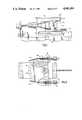
- FIG. 1is a side elevation partially broken away of a servo control according to the present invention
- FIG. 2is a top plan view of the device of FIG. 1.
- FIG. 3is a schematic block diagram of a control system for the present invention.
- FIG. 4is a cross sectional view of the track and mounting platform of the servo motor control of the present invention.
- FIG. 5is a detailed view of the servo quadrant and cable attachment detail of the present invention.
- FIG. 1there is shown a servo control articulation system 10 for a borescope.
- the chassis of the control moduleis shown at 12 and the chassis carries therein a T-shaped mounting rail 14 on which is slidably mounted a U-shaped bracket 16 (FIG. 4).
- Plate 16carries thereon the servo motors 18 and 20 (FIG. 2), each of which has mounted on its output shaft semi-circular quadrants 22 and 24.
- Mounted at the opposite ends of the diameter of the semi-circular quadrant 24 on motor 20are cable retaining ferrules 26 and 28 (FIG. 5) to which are connected the wires 30 and 32 for actuating the bendable tube section of the borescope insertion tube in one direction.
- the other servo motor 18carries on its quadrant 22 a similar pair of adjustable cable ferrules 26' and 28' which are connected to the second pair of actuating wires 30' and 32' for controlling the insertion tube distal end in a plane at ninety degrees to the plane of motion of the first pair.
- the connection of two pair of wires at right angles to each other at the distal end of an insertion tubeis common and shown in the references previously cited.
- a steering control board 36Pivotally mounted by the hinges 32 directly above the servo motors is a steering control board 36 which carries thereon a pulse generating circuit and a pulse width modulator section 62, together with a centering section 64 and a gain and offset section 66 for matching a joystick type actuator 40 to the servo motors 18 and 20 and limiting rotation thereof.
- the details of the control circuitwill be described in connection with FIG. 3.
- the servo motorsare mounted on bracket 16 which is slidably mounted on the T-bar 14 (FIG. 4).
- the cables 30-32 and 30'-32'which extend out through the insertion tube to the bendable section at the distal end, are connected physically to the quadrants 22 and 24 at the opposite ends of a diameter as described above.
- one cablewill be tensioned to bend the insertion tube in that direction and the opposite cable of the pair will have the tension removed so that it can move with the tube end as it bends.
- the modulator 62includes an oscillator which generates pulses at the desired frequency and circuitry to vary the pulse width in accordance with the voltage applied at the inputs 63 and 63' of the pulse width modulator. Typical pulse widths for the oscillator pulse may vary from 1.0 milliseconds to 2.0 milliseconds.
- the tension in the wiretends to exceed the desired amount, it will pull on its servo motor which is fixed to the bracket 16 mounted on the track 14.
- the bracket 16is connected to the chassis by a pair of springs 50 which are selected to yield above a given predetermined tension or force applied thereto.
- both servo motorsare mounted on the same plate, excess tension in either pair of wires will move the entire assembly and will tend to relieve tension on both pairs of wires. Generally speaking, if excess tension is being encountered in one pair, the other pair will also be subjected to excessive tension so that the two springs are sized to prevent excessive tension in either or both pairs.
- the servo motors 18 and 20are actuated by applying a pulse, typically five volts, of a desired width which represents a particular angular position of the quadrant 22 and 24.
- the pulsesare applied at any desired frequency, for instance sixty hertz, and as long as the pulse width remains constant the servo motors remain stationary.
- a predetermined pulse widthis chosen that will maintain the steerable section of the insertion tube in the straight position when the joystick control is in the neutral position and then the pulse width is decreased or increased proportional to the movement of the joystick actuator 41 to bend the distal end of the insertion tube the desired amount.
- Rotation of the servo motorsis accomplished by applying the voltage pulses to the motors.
- the degree of rotationis controlled by varying the width of the pulses applied to the servo motors through the modulator 62.
- the gain adjustment section of the steering control board in FIG. 3determines the maximum range of pulse widths that can be created by the modulator 62 and hence the maximum rotation of the quadrants.
- Potentiometers 52 and 53are originally set to permit rotation of about plus or minus sixty-five degrees maximum.
- the amount of tension that can be applied by the servo motorsis determined in part by the original adjustment of the cable retaining ferrules 26 and 28 and then by the maximum degree of rotation of the quadrant.
- the degree of rotation of the quadrants 22 and 24is determined by the amount of displacement of the joystick and by the position of potentiometers 52 and 53 in FIG. 3. This adjustment can be changed to compensate for stretch in the wires over time by allowing the servo to rotate further and to thus still maintain the tension in the wire for maximum bending of the bendable distal end of the borescope insertion tube.
- the ferrules 26 and 28can be mechanically tightened to take up slack and then the potentiometers readjusted to provide the desired tension.
- This potentiometer adjustmentis a simple screwdriver adjustment on the board 36 which can be readily done in the field without sophisticated instruments. This saves many costly and time consuming returns of the insertion tube to the factory for refurbishing and readjustment. Since the springs are set so that the tension on the wires will not exceed their elastic limit, excessive stretching of the wires is prevented, and only a slight stretching over time is encountered, which can normally be completely compensated for by the foregoing means.
- the ferrules 26 and 28are threadably mounted in the periphery of the quadrant 24 and carry therethrough the wires 30 and 32 with a termination that can either be crimped or soldered in the form of a ball 38 to secure the wire within the ferrule.
- the ferrules 26 and 28can then be adjusted to tension the wires 30 and 32 sufficiently to position the bendable section of the borescope insertion tube at center position in the corresponding plane for wires 30 and 32.
- the ferrules 26' and 28'can similarly be adjusted for wires 30' and 32'.
- each ferruleis mounted in a slight recess in the quadrant such that the wire, as it exits the ferrule, makes a smooth transition into the channel 42 in the periphery of the quadrant such that when the quadrant is rotated from the center position, the wire will not be cut by the quadrant as it exits the ferrule.
- the ferrulealso has a chamfer 44 to enhance this smooth transition.
- the modulator 62includes an oscillator which generates pulses at the desired frequency and circuitry to vary the pulse width in accordance with the voltage applied at the input 63 and 63' of the pulse width modulator.
- the joystick control 40consists basically of two potentiometers 54 and 55, one actuated by the "x" direction of motion of the joystick 41 and the other actuated by the "y" direction of motion of the joystick 41. As may be seen in FIG. 3, a positive five volt power source is connected to resistors 54 and 55 with the other side of each potentiometer connected to ground.
- calibration compensation potentiometers 56 and 57are provided to compensate for any slight misalignment there may be in the mechanical construction of the joystick.
- Each potentiometer 56 and 57is connected from a -12 volt power supply to ground, and they are adjusted to yield zero voltage at the test points 58 and 59 on initial set up and calibration.
- the servo motors 18 and 20have built-in variations that must be compensated for to obtain the desired zero bending in the neutral position.
- a centering adjustmentis provided by another pair of potentiometers 60 and 61, connected between -12 volts and ground.
- the potentiometers 60 and 61are adjusted to provide an input voltage at 63 and 63' to pulse width modulator 62, corresponding to the zero bending of the distal end of the insertion tube while also compensating for any anomalies in the servo motors themselves.
- the neutral pulse widthis set at 1.5 milliseconds, which allows plus or minus variation from 1.0 milliseconds to 2.0 milliseconds pulse widths.
- Variations of the voltage at 63 and 63'will cause the pulse width produced by modulator 62 to increase or decrease which will in turn cause servo motors 18 and 20 to rotate in a clockwise or counterclockwise direction from the center neutral position to actuate the bendable distal end of the insertion tube in the desired direction.
- the modulator 62provides a series of pulses at a frequency of typically sixty hertz, which vary in width as the lever 41 is moved, creating an offsetting voltage from the neutral position, proportional to the amount of movement of the lever.
- This voltageis fed from joystick control 40 through the Offset Null adjustments 56 and 57 and Maximum Gain adjustments 52 and 53 and centering adjustment potentiometers 60 and 61 which drive the respective channels in the modulator to either increase or decrease the width of the pulses.
- the greater the variation from the neutral voltage at 63 and 63'either plus or minus, the greater the degree of rotation of the servo motors from the neutral position.
- the deviceIn operation the device is adjusted so that the joystick and the servo motors are "zeroed out” in the neutral position to provide zero bending of the steerable section of the insertion tube.
- the normal maximum deflection of the servo motorsmay be adjusted by potentiometers 52 and 53, for instance, to plus or minus forty-five degrees in each direction for the original cables which, in the unobstructed and uncoiled condition, will actuate the steerable portion of the insertion tube to its maximum bending in each plane of motion.
- the particular servo motor actuating these cablesmay be adjusted to rotate plus or minus a greater amount, up to ninety to one-hundred degrees at the extreme, which is effectuated by changing potentiometers 52 and 53 to provide greater pulse width out of the pulse width modulator 62 so as to cause the greater rotation of the servo motor. Since this is now a simple screwdriver adjustment of a potentiometer, it can be easily done by field operating personnel and thus the insertion tube control can be kept in optimum condition without having to return it to the factory for calibration and adjustment.
- cables 30 and 32 or cables 30' and 32'can be independently adjusted by their respective potentiometers 52 or 53 for optimum actuation control.
- the operator of the borescopecan now, with one hand, direct the insertion tube to the precise location desired by monitoring the image on the tv screen and actuating the bendable tip to move in the direction it is desired to go as the insertion tube is inserted into the cavity to be inspected.
- the operatorcannot damage the insertion tube control system because if he hits an obstruction or if he exceeds the predetermined tension of the actuation cables, the entire servo control mechanism will be moved along the T track 14 against the springs 50, which are chosen to yield before the actuating cables are stretched.
Landscapes
- Health & Medical Sciences (AREA)
- Life Sciences & Earth Sciences (AREA)
- Surgery (AREA)
- Engineering & Computer Science (AREA)
- Biomedical Technology (AREA)
- Molecular Biology (AREA)
- Pathology (AREA)
- Radiology & Medical Imaging (AREA)
- Nuclear Medicine, Radiotherapy & Molecular Imaging (AREA)
- Biophysics (AREA)
- Physics & Mathematics (AREA)
- Heart & Thoracic Surgery (AREA)
- Medical Informatics (AREA)
- Optics & Photonics (AREA)
- Animal Behavior & Ethology (AREA)
- General Health & Medical Sciences (AREA)
- Public Health (AREA)
- Veterinary Medicine (AREA)
- Mechanical Engineering (AREA)
- Endoscopes (AREA)
- Instruments For Viewing The Inside Of Hollow Bodies (AREA)
Abstract
Description
Claims (11)
Priority Applications (1)
| Application Number | Priority Date | Filing Date | Title |
|---|---|---|---|
| US07/417,554US4941454A (en) | 1989-10-05 | 1989-10-05 | Servo actuated steering mechanism for borescope or endoscope |
Applications Claiming Priority (1)
| Application Number | Priority Date | Filing Date | Title |
|---|---|---|---|
| US07/417,554US4941454A (en) | 1989-10-05 | 1989-10-05 | Servo actuated steering mechanism for borescope or endoscope |
Publications (1)
| Publication Number | Publication Date |
|---|---|
| US4941454Atrue US4941454A (en) | 1990-07-17 |
Family
ID=23654448
Family Applications (1)
| Application Number | Title | Priority Date | Filing Date |
|---|---|---|---|
| US07/417,554Expired - LifetimeUS4941454A (en) | 1989-10-05 | 1989-10-05 | Servo actuated steering mechanism for borescope or endoscope |
Country Status (1)
| Country | Link |
|---|---|
| US (1) | US4941454A (en) |
Cited By (124)
| Publication number | Priority date | Publication date | Assignee | Title |
|---|---|---|---|---|
| US5347989A (en)* | 1992-09-11 | 1994-09-20 | Welch Allyn, Inc. | Control mechanism for steerable elongated probe having a sealed joystick |
| US5350355A (en)* | 1992-02-14 | 1994-09-27 | Automated Medical Instruments, Inc. | Automated surgical instrument |
| US5359994A (en)* | 1994-01-24 | 1994-11-01 | Welch Allyn, Inc. | Proximal steering cable adjustment |
| US5365928A (en)* | 1992-11-25 | 1994-11-22 | Medrad, Inc. | Endorectal probe with planar moveable MRI coil |
| US5400769A (en)* | 1991-02-18 | 1995-03-28 | Olympus Optical Co., Ltd. | Electrically bendable endoscope apparatus having controlled fixed bending speed |
| US5415158A (en)* | 1993-06-11 | 1995-05-16 | Clarus Medical Systems, Inc. | Flexible endoscope with force limiting spring coupler |
| US5469840A (en)* | 1991-12-10 | 1995-11-28 | Olympus Optical, Ltd. | Electromotive warping type endoscope with velocity control |
| US5472017A (en)* | 1992-11-17 | 1995-12-05 | Life Medical Technologies, Inc. | Deflectable catheter |
| EP0700692A1 (en)* | 1994-09-06 | 1996-03-13 | Guided Medical Systems Inc. | Catheter Control |
| US5549542A (en)* | 1992-11-17 | 1996-08-27 | Life Medical Technologies, Inc. | Deflectable endoscope |
| EP0696926A4 (en)* | 1993-05-06 | 1997-01-08 | Ep Technologies | Catheter steering assembly providing asymmetric curve configurations |
| US5626595A (en)* | 1992-02-14 | 1997-05-06 | Automated Medical Instruments, Inc. | Automated surgical instrument |
| FR2740688A1 (en)* | 1995-11-07 | 1997-05-09 | Tokendo Sarl | Video-endoscope with flexible connection tube and adjustable head |
| WO1998008429A1 (en)* | 1996-08-30 | 1998-03-05 | The Whitaker Corporation | Apparatus to flex a bendable probe |
| US5813976A (en)* | 1996-04-02 | 1998-09-29 | Filipi; Charles J. | Stabilizing instrumentation for the performing of endoscopic surgical procedures |
| US5891088A (en)* | 1990-02-02 | 1999-04-06 | Ep Technologies, Inc. | Catheter steering assembly providing asymmetric left and right curve configurations |
| US6371907B1 (en)* | 1996-11-18 | 2002-04-16 | Olympus Optical Co., Ltd. | Endoscope apparatus driving manipulation wires with drive motor in drum portion |
| US20020087049A1 (en)* | 1998-02-24 | 2002-07-04 | Brock David L. | Flexible instrument |
| US6482148B1 (en)* | 1997-06-27 | 2002-11-19 | Keymed (Medical & Industrial Equipment) Ltd. | Optical scope with measuring system |
| US6517565B1 (en) | 1999-06-02 | 2003-02-11 | Power Medical Interventions, Inc. | Carriage assembly for controlling a steering wire steering mechanism within a flexible shaft |
| US20030194793A1 (en)* | 1997-03-31 | 2003-10-16 | Genentech, Inc. | Secreted and transmembrane polypeptides and nucleic acids encoding the same |
| US6669629B2 (en) | 2001-04-24 | 2003-12-30 | Olympus Optical Co., Ltd. | Endoscope system comprising an electrically bendable endoscope |
| US20040049205A1 (en)* | 2002-09-09 | 2004-03-11 | Endo Via Medical, Inc. | Surgical instrument coupling mechanism |
| US20040138530A1 (en)* | 2002-07-15 | 2004-07-15 | Olympus Optical Co., Ltd. | Apparatus for traction positional control |
| US20040176751A1 (en)* | 2002-08-14 | 2004-09-09 | Endovia Medical, Inc. | Robotic medical instrument system |
| US6793652B1 (en) | 1999-06-02 | 2004-09-21 | Power Medical Interventions, Inc. | Electro-mechanical surgical device |
| US20040183900A1 (en)* | 2003-03-20 | 2004-09-23 | Everest Vit | Method and system for automatically detecting defects in remote video inspection applications |
| US20040193146A1 (en)* | 2001-02-15 | 2004-09-30 | Endo Via Medical, Inc. | Robotically controlled surgical instruments |
| US20040204628A1 (en)* | 2003-01-17 | 2004-10-14 | Tokendo | Videoendoscope |
| FR2855275A1 (en)* | 2003-05-22 | 2004-11-26 | Tokendo | Video endoscope for observing target, has visualization case that is integrated to lateral face of control case by articulation formed by connector, where control case is elongated between distal and proximal ends of inspection tube |
| US6843403B2 (en) | 1999-06-02 | 2005-01-18 | Power Medical Interventions, Inc. | Surgical clamping, cutting and stapling device |
| US20050054899A1 (en)* | 2003-05-13 | 2005-03-10 | Olympus Corporation | Endoscope apparatus |
| US20050129108A1 (en)* | 2003-01-29 | 2005-06-16 | Everest Vit, Inc. | Remote video inspection system |
| US20050168571A1 (en)* | 2004-01-29 | 2005-08-04 | Everest Vit, Inc. | Method and apparatus for improving the operation of a remote viewing device |
| US6981941B2 (en) | 1999-06-02 | 2006-01-03 | Power Medical Interventions | Electro-mechanical surgical device |
| US20060020213A1 (en)* | 2004-07-09 | 2006-01-26 | Whitman Michael P | Surgical imaging device |
| US20060069305A1 (en)* | 2004-09-30 | 2006-03-30 | Boston Scientific Scimed, Inc. | Device with enhanced indication of use and prevention of re-use |
| US20060072903A1 (en)* | 2001-02-22 | 2006-04-06 | Everest Vit, Inc. | Method and system for storing calibration data within image files |
| US7032798B2 (en) | 1999-06-02 | 2006-04-25 | Power Medical Interventions, Inc. | Electro-mechanical surgical device |
| US7090683B2 (en) | 1998-02-24 | 2006-08-15 | Hansen Medical, Inc. | Flexible instrument |
| US20070070340A1 (en)* | 2005-06-22 | 2007-03-29 | Karpen Thomas W | Remote video inspection system integrating audio communication functionality |
| US20070091183A1 (en)* | 2005-10-21 | 2007-04-26 | Ge Inspection Technologies, Lp | Method and apparatus for adapting the operation of a remote viewing device to correct optical misalignment |
| US20070150155A1 (en)* | 2004-08-19 | 2007-06-28 | Toshimasa Kawai | Electrically-operated curving control device |
| US20070156018A1 (en)* | 2005-06-24 | 2007-07-05 | Krauter Allan I | Insertion tube storage carousel |
| US20070156021A1 (en)* | 2005-09-14 | 2007-07-05 | Bradford Morse | Remote imaging apparatus having an adaptive lens |
| US7241263B2 (en) | 2004-09-30 | 2007-07-10 | Scimed Life Systems, Inc. | Selectively rotatable shaft coupler |
| US20070161861A1 (en)* | 2004-08-19 | 2007-07-12 | Olympus Corporation | Electrically-operated curving control device |
| US20070187574A1 (en)* | 2006-02-13 | 2007-08-16 | Ge Inspection Technologies, Lp | Electronic imaging device with photosensor arrays |
| US20070226258A1 (en)* | 2006-03-27 | 2007-09-27 | Thomas Eldred Lambdin | Article inspection apparatus |
| US20070233052A1 (en)* | 1998-02-24 | 2007-10-04 | Hansen Medical, Inc. | Interchangeable surgical instrument |
| US20070239170A1 (en)* | 1998-02-24 | 2007-10-11 | Brock David L | Flexible instrument |
| US20080033453A1 (en)* | 1998-02-24 | 2008-02-07 | Hansen Medical, Inc. | Interchangeable surgical instrument |
| US20080119824A1 (en)* | 2001-02-15 | 2008-05-22 | Hansen Medical, Inc. | Coaxial catheter system |
| US20080151046A1 (en)* | 2006-12-22 | 2008-06-26 | Ge Inspection Technologies, Lp | Heat protection systems and methods for remote viewing devices |
| US20080157994A1 (en)* | 2006-12-29 | 2008-07-03 | General Electric Company | IP based voice communication enabled inspection system |
| US20080158348A1 (en)* | 2006-12-29 | 2008-07-03 | General Electric Company | Inspection apparatus having illumination assembly |
| US20080177284A1 (en)* | 2001-02-15 | 2008-07-24 | Hansen Medical, Inc. | Robotically controlled medical instrument |
| US7413543B2 (en) | 2003-04-01 | 2008-08-19 | Scimed Life Systems, Inc. | Endoscope with actively cooled illumination sources |
| US7422559B2 (en) | 2004-06-16 | 2008-09-09 | Ge Inspection Technologies, Lp | Borescope comprising fluid supply system |
| US20080275297A1 (en)* | 2007-05-01 | 2008-11-06 | Ethicon Endo-Surgery, Inc. | Endoscopic guide device |
| US7479106B2 (en) | 2004-09-30 | 2009-01-20 | Boston Scientific Scimed, Inc. | Automated control of irrigation and aspiration in a single-use endoscope |
| US20090076330A1 (en)* | 2007-09-19 | 2009-03-19 | Fujifilm Corporation | Endoscope |
| US20090109429A1 (en)* | 2007-10-26 | 2009-04-30 | Joshua Lynn Scott | Inspection apparatus having heat sink assembly |
| US20090109045A1 (en)* | 2007-10-26 | 2009-04-30 | Delmonico James J | Battery and power management for industrial inspection handset |
| US20090106948A1 (en)* | 2007-10-26 | 2009-04-30 | Lopez Joseph V | Method and apparatus for retaining elongated flexible articles including visual inspection apparatus inspection probes |
| US20090109283A1 (en)* | 2007-10-26 | 2009-04-30 | Joshua Lynn Scott | Integrated storage for industrial inspection handset |
| US7564626B2 (en) | 2002-01-25 | 2009-07-21 | Ge Inspection Technologies Lp | Stereo-measurement borescope with 3-D viewing |
| WO2009099633A1 (en)* | 2008-02-07 | 2009-08-13 | Gumbs Andrew A | Remote endoscope handle manipulation |
| US7578786B2 (en) | 2003-04-01 | 2009-08-25 | Boston Scientific Scimed, Inc. | Video endoscope |
| US7591783B2 (en) | 2003-04-01 | 2009-09-22 | Boston Scientific Scimed, Inc. | Articulation joint for video endoscope |
| US20090240106A1 (en)* | 2008-03-05 | 2009-09-24 | Board Of Regents, The University Of Texas System | Endoscope With a Stimulating Electrode For Peripheral Nerve Blocks Under Direct Vision |
| US7597662B2 (en) | 2004-09-30 | 2009-10-06 | Boston Scientific Scimed, Inc. | Multi-fluid delivery system |
| US7695485B2 (en) | 2001-11-30 | 2010-04-13 | Power Medical Interventions, Llc | Surgical device |
| US7713190B2 (en) | 1998-02-24 | 2010-05-11 | Hansen Medical, Inc. | Flexible instrument |
| US7743960B2 (en) | 2002-06-14 | 2010-06-29 | Power Medical Interventions, Llc | Surgical device |
| US7751870B2 (en) | 2002-01-30 | 2010-07-06 | Power Medical Interventions, Llc | Surgical imaging device |
| US7846107B2 (en) | 2005-05-13 | 2010-12-07 | Boston Scientific Scimed, Inc. | Endoscopic apparatus with integrated multiple biopsy device |
| US20100314443A1 (en)* | 2009-06-12 | 2010-12-16 | Hand Held Products, Inc. | Portable Data Terminal |
| US20100324363A1 (en)* | 2008-03-05 | 2010-12-23 | Board Of Regents, The University Of Texas System | Disposable sheath designs for the stimulating endoscope and needle endoscopes having distal electrodes for nerve block under direct vision and methods for making and using same |
| US7918230B2 (en) | 2007-09-21 | 2011-04-05 | Tyco Healthcare Group Lp | Surgical device having a rotatable jaw portion |
| DE202010006478U1 (en) | 2009-11-19 | 2011-04-07 | Karl Storz Gmbh & Co. Kg | Endoscope with flexible endoscope shaft |
| US20110118756A1 (en)* | 1998-02-24 | 2011-05-19 | Hansen Medical, Inc. | Interchangeable surgical instrument |
| US7951071B2 (en) | 1999-06-02 | 2011-05-31 | Tyco Healthcare Group Lp | Moisture-detecting shaft for use with an electro-mechanical surgical device |
| US7955255B2 (en) | 2006-04-20 | 2011-06-07 | Boston Scientific Scimed, Inc. | Imaging assembly with transparent distal cap |
| US7963433B2 (en) | 2007-09-21 | 2011-06-21 | Tyco Healthcare Group Lp | Surgical device having multiple drivers |
| US7967759B2 (en) | 2006-01-19 | 2011-06-28 | Boston Scientific Scimed, Inc. | Endoscopic system with integrated patient respiratory status indicator |
| US20110213360A1 (en)* | 2010-02-26 | 2011-09-01 | Tyco Healthcare Group Lp | Tensioning Mechanism for Articulation Drive Cables |
| US20110213361A1 (en)* | 2010-02-26 | 2011-09-01 | Tyco Healthcare Group Lp | De-Tensioning Mechanism for Articulation Drive Cables |
| US8016855B2 (en) | 2002-01-08 | 2011-09-13 | Tyco Healthcare Group Lp | Surgical device |
| US8025199B2 (en) | 2004-02-23 | 2011-09-27 | Tyco Healthcare Group Lp | Surgical cutting and stapling device |
| US8052597B2 (en) | 2005-08-30 | 2011-11-08 | Boston Scientific Scimed, Inc. | Method for forming an endoscope articulation joint |
| US8083671B2 (en) | 2004-09-30 | 2011-12-27 | Boston Scientific Scimed, Inc. | Fluid delivery system for use with an endoscope |
| US20120004648A1 (en)* | 2009-03-06 | 2012-01-05 | Seung Wook Choi | Surgical instrument |
| US8097003B2 (en) | 2005-05-13 | 2012-01-17 | Boston Scientific Scimed, Inc. | Endoscopic apparatus with integrated variceal ligation device |
| US8118732B2 (en) | 2003-04-01 | 2012-02-21 | Boston Scientific Scimed, Inc. | Force feedback control system for video endoscope |
| US8199187B2 (en) | 2004-09-30 | 2012-06-12 | Boston Scientific Scimed, Inc. | Adapter for use with digital imaging medical device |
| US8202265B2 (en) | 2006-04-20 | 2012-06-19 | Boston Scientific Scimed, Inc. | Multiple lumen assembly for use in endoscopes or other medical devices |
| US8213676B2 (en) | 2006-12-20 | 2012-07-03 | Ge Inspection Technologies Lp | Inspection apparatus method and apparatus comprising motion responsive control |
| US8262560B2 (en) | 2001-04-20 | 2012-09-11 | Tyco Healthcare Group Lp | Imaging device for use with a surgical device |
| US8310604B2 (en) | 2007-10-26 | 2012-11-13 | GE Sensing & Inspection Technologies, LP | Visual inspection apparatus having light source bank |
| US8353860B2 (en) | 2004-09-30 | 2013-01-15 | Boston Scientific Scimed, Inc. | Device for obstruction removal with specific tip structure |
| US8357148B2 (en) | 2004-09-30 | 2013-01-22 | Boston Scientific Scimed, Inc. | Multi-functional endoscopic system for use in electrosurgical applications |
| US8414598B2 (en) | 1998-02-24 | 2013-04-09 | Hansen Medical, Inc. | Flexible instrument |
| US8414505B1 (en) | 2001-02-15 | 2013-04-09 | Hansen Medical, Inc. | Catheter driver system |
| US8535219B2 (en) | 2003-04-01 | 2013-09-17 | Boston Scientific Scimed, Inc. | Fluid manifold for endoscope system |
| US8696552B2 (en) | 2002-09-30 | 2014-04-15 | Covidien Lp | Self-contained sterilizable surgical system |
| US8810636B2 (en) | 2006-12-20 | 2014-08-19 | Ge Inspection Technologies, Lp | Inspection apparatus method and apparatus comprising selective frame output |
| US8836937B2 (en) | 2012-11-19 | 2014-09-16 | General Electric Company | Actuatable visual inspection device |
| US8888684B2 (en) | 2006-03-27 | 2014-11-18 | Boston Scientific Scimed, Inc. | Medical devices with local drug delivery capabilities |
| WO2014183853A3 (en)* | 2013-05-17 | 2015-01-08 | Martin Neumann | Endoscopic device |
| US9113878B2 (en) | 2002-01-08 | 2015-08-25 | Covidien Lp | Pinion clip for right angle linear cutter |
| US9211134B2 (en) | 2012-04-09 | 2015-12-15 | Carefusion 2200, Inc. | Wrist assembly for articulating laparoscopic surgical instruments |
| US9333040B2 (en) | 2012-02-02 | 2016-05-10 | Transenterix Surgical, Inc. | Mechanized multi-instrument surgical system |
| US9404871B2 (en) | 2012-01-09 | 2016-08-02 | General Electric Company | Method and system for steering an insertion tube of a video inspection device |
| JP2017029225A (en)* | 2015-07-29 | 2017-02-09 | オリンパス株式会社 | Endoscope apparatus |
| US9706907B2 (en) | 2008-02-07 | 2017-07-18 | Institute For Cancer Research | Remote endoscope handle manipulation |
| DE102016105767A1 (en)* | 2016-03-30 | 2017-10-05 | Digital Endoscopy Gmbh | Endoscope control device and endoscope |
| US9883880B2 (en)* | 2008-08-04 | 2018-02-06 | Covidien Lp | Articulating surgical device |
| US10291850B2 (en) | 2006-12-20 | 2019-05-14 | General Electric Company | Inspection apparatus method and apparatus comprising selective frame output |
| US20210059506A1 (en)* | 2018-06-28 | 2021-03-04 | Olympus Corporation | Wire fixing structure and endoscope |
| US10942964B2 (en) | 2009-02-02 | 2021-03-09 | Hand Held Products, Inc. | Apparatus and method of embedding meta-data in a captured image |
| US20210369082A1 (en)* | 2005-11-22 | 2021-12-02 | Intuitive Surgical Operations, Inc. | System for determining the shape of a bendable instrument |
| US11586275B2 (en) | 2020-01-09 | 2023-02-21 | Baker Hughes Oilfield Operations Llc | Cable force adjustment |
| WO2023202010A1 (en)* | 2022-04-22 | 2023-10-26 | 湖南省华芯医疗器械有限公司 | Endoscope connecting structure, endoscope handle, and endoscope |
Citations (9)
| Publication number | Priority date | Publication date | Assignee | Title |
|---|---|---|---|---|
| US4253447A (en)* | 1978-10-16 | 1981-03-03 | Welch Allyn, Inc. | Color endoscope with charge coupled device and television viewing |
| US4261344A (en)* | 1979-09-24 | 1981-04-14 | Welch Allyn, Inc. | Color endoscope |
| US4294233A (en)* | 1978-04-12 | 1981-10-13 | Kabushiki Kaisha Medos Kenkyusho | Slack absorbing device for an endoscope |
| US4491865A (en)* | 1982-09-29 | 1985-01-01 | Welch Allyn, Inc. | Image sensor assembly |
| US4559928A (en)* | 1981-10-22 | 1985-12-24 | Olympus Optical Co., Ltd. | Endoscope apparatus with motor-driven bending mechanism |
| US4621618A (en)* | 1984-02-28 | 1986-11-11 | Olympus Optical Company, Ltd. | Dual viewing and control apparatus for endoscope |
| US4659195A (en)* | 1986-01-31 | 1987-04-21 | American Hospital Supply Corporation | Engine inspection system |
| US4688555A (en)* | 1986-04-25 | 1987-08-25 | Circon Corporation | Endoscope with cable compensating mechanism |
| US4787369A (en)* | 1987-08-14 | 1988-11-29 | Welch Allyn, Inc. | Force relieving, force limiting self-adjusting steering for borescope or endoscope |
- 1989
- 1989-10-05USUS07/417,554patent/US4941454A/ennot_activeExpired - Lifetime
Patent Citations (9)
| Publication number | Priority date | Publication date | Assignee | Title |
|---|---|---|---|---|
| US4294233A (en)* | 1978-04-12 | 1981-10-13 | Kabushiki Kaisha Medos Kenkyusho | Slack absorbing device for an endoscope |
| US4253447A (en)* | 1978-10-16 | 1981-03-03 | Welch Allyn, Inc. | Color endoscope with charge coupled device and television viewing |
| US4261344A (en)* | 1979-09-24 | 1981-04-14 | Welch Allyn, Inc. | Color endoscope |
| US4559928A (en)* | 1981-10-22 | 1985-12-24 | Olympus Optical Co., Ltd. | Endoscope apparatus with motor-driven bending mechanism |
| US4491865A (en)* | 1982-09-29 | 1985-01-01 | Welch Allyn, Inc. | Image sensor assembly |
| US4621618A (en)* | 1984-02-28 | 1986-11-11 | Olympus Optical Company, Ltd. | Dual viewing and control apparatus for endoscope |
| US4659195A (en)* | 1986-01-31 | 1987-04-21 | American Hospital Supply Corporation | Engine inspection system |
| US4688555A (en)* | 1986-04-25 | 1987-08-25 | Circon Corporation | Endoscope with cable compensating mechanism |
| US4787369A (en)* | 1987-08-14 | 1988-11-29 | Welch Allyn, Inc. | Force relieving, force limiting self-adjusting steering for borescope or endoscope |
Cited By (265)
| Publication number | Priority date | Publication date | Assignee | Title |
|---|---|---|---|---|
| US6485455B1 (en) | 1990-02-02 | 2002-11-26 | Ep Technologies, Inc. | Catheter steering assembly providing asymmetric left and right curve configurations |
| US5891088A (en)* | 1990-02-02 | 1999-04-06 | Ep Technologies, Inc. | Catheter steering assembly providing asymmetric left and right curve configurations |
| US5400769A (en)* | 1991-02-18 | 1995-03-28 | Olympus Optical Co., Ltd. | Electrically bendable endoscope apparatus having controlled fixed bending speed |
| US5469840A (en)* | 1991-12-10 | 1995-11-28 | Olympus Optical, Ltd. | Electromotive warping type endoscope with velocity control |
| US5632758A (en)* | 1992-02-14 | 1997-05-27 | Automated Medical Instruments, Inc. | Automated surgical instrument |
| US5350355A (en)* | 1992-02-14 | 1994-09-27 | Automated Medical Instruments, Inc. | Automated surgical instrument |
| US5626595A (en)* | 1992-02-14 | 1997-05-06 | Automated Medical Instruments, Inc. | Automated surgical instrument |
| US5347989A (en)* | 1992-09-11 | 1994-09-20 | Welch Allyn, Inc. | Control mechanism for steerable elongated probe having a sealed joystick |
| US5472017A (en)* | 1992-11-17 | 1995-12-05 | Life Medical Technologies, Inc. | Deflectable catheter |
| US5549542A (en)* | 1992-11-17 | 1996-08-27 | Life Medical Technologies, Inc. | Deflectable endoscope |
| US5365928A (en)* | 1992-11-25 | 1994-11-22 | Medrad, Inc. | Endorectal probe with planar moveable MRI coil |
| EP0696926A4 (en)* | 1993-05-06 | 1997-01-08 | Ep Technologies | Catheter steering assembly providing asymmetric curve configurations |
| US5415158A (en)* | 1993-06-11 | 1995-05-16 | Clarus Medical Systems, Inc. | Flexible endoscope with force limiting spring coupler |
| US5359994A (en)* | 1994-01-24 | 1994-11-01 | Welch Allyn, Inc. | Proximal steering cable adjustment |
| EP0700692A1 (en)* | 1994-09-06 | 1996-03-13 | Guided Medical Systems Inc. | Catheter Control |
| FR2740688A1 (en)* | 1995-11-07 | 1997-05-09 | Tokendo Sarl | Video-endoscope with flexible connection tube and adjustable head |
| US5813976A (en)* | 1996-04-02 | 1998-09-29 | Filipi; Charles J. | Stabilizing instrumentation for the performing of endoscopic surgical procedures |
| WO1998008429A1 (en)* | 1996-08-30 | 1998-03-05 | The Whitaker Corporation | Apparatus to flex a bendable probe |
| US5833616A (en)* | 1996-08-30 | 1998-11-10 | The Whitaker Corporation | Navigable probe and rotating motor control apparatus |
| US6371907B1 (en)* | 1996-11-18 | 2002-04-16 | Olympus Optical Co., Ltd. | Endoscope apparatus driving manipulation wires with drive motor in drum portion |
| US20030194793A1 (en)* | 1997-03-31 | 2003-10-16 | Genentech, Inc. | Secreted and transmembrane polypeptides and nucleic acids encoding the same |
| US6482148B1 (en)* | 1997-06-27 | 2002-11-19 | Keymed (Medical & Industrial Equipment) Ltd. | Optical scope with measuring system |
| US8414598B2 (en) | 1998-02-24 | 2013-04-09 | Hansen Medical, Inc. | Flexible instrument |
| US7918861B2 (en) | 1998-02-24 | 2011-04-05 | Hansen Medical, Inc. | Flexible instrument |
| US7758569B2 (en) | 1998-02-24 | 2010-07-20 | Hansen Medical, Inc. | Interchangeable surgical instrument |
| US7713190B2 (en) | 1998-02-24 | 2010-05-11 | Hansen Medical, Inc. | Flexible instrument |
| US8303576B2 (en) | 1998-02-24 | 2012-11-06 | Hansen Medical, Inc. | Interchangeable surgical instrument |
| US7775972B2 (en) | 1998-02-24 | 2010-08-17 | Hansen Medical, Inc. | Flexible instrument |
| US20070250073A1 (en)* | 1998-02-24 | 2007-10-25 | Brock David L | Flexible instrument |
| US20070233052A1 (en)* | 1998-02-24 | 2007-10-04 | Hansen Medical, Inc. | Interchangeable surgical instrument |
| US7867241B2 (en) | 1998-02-24 | 2011-01-11 | Hansen Medical, Inc. | Flexible instrument |
| US20070239170A1 (en)* | 1998-02-24 | 2007-10-11 | Brock David L | Flexible instrument |
| US7901399B2 (en) | 1998-02-24 | 2011-03-08 | Hansen Medical, Inc. | Interchangeable surgical instrument |
| US20070250074A1 (en)* | 1998-02-24 | 2007-10-25 | Brock David L | Flexible instrument |
| US20070255291A1 (en)* | 1998-02-24 | 2007-11-01 | Brock David L | Flexible instrument |
| US20070260115A1 (en)* | 1998-02-24 | 2007-11-08 | Brock David L | Flexible instrument |
| US20080033453A1 (en)* | 1998-02-24 | 2008-02-07 | Hansen Medical, Inc. | Interchangeable surgical instrument |
| US7371210B2 (en) | 1998-02-24 | 2008-05-13 | Hansen Medical, Inc. | Flexible instrument |
| US8114097B2 (en) | 1998-02-24 | 2012-02-14 | Hansen Medical, Inc. | Flexible instrument |
| US20020087049A1 (en)* | 1998-02-24 | 2002-07-04 | Brock David L. | Flexible instrument |
| US20110118756A1 (en)* | 1998-02-24 | 2011-05-19 | Hansen Medical, Inc. | Interchangeable surgical instrument |
| US7090683B2 (en) | 1998-02-24 | 2006-08-15 | Hansen Medical, Inc. | Flexible instrument |
| US7931586B2 (en) | 1998-02-24 | 2011-04-26 | Hansen Medical, Inc. | Flexible instrument |
| US7905828B2 (en) | 1998-02-24 | 2011-03-15 | Hansen Medical, Inc. | Flexible instrument |
| US10314659B2 (en) | 1999-06-02 | 2019-06-11 | Covidien Lp | Electro-mechanical surgical device |
| US6849071B2 (en) | 1999-06-02 | 2005-02-01 | Power Medical Interventions, Inc. | Electro-mechanical surgical device |
| US9113847B2 (en) | 1999-06-02 | 2015-08-25 | Covidien Lp | Electro-mechanical surgical device |
| US9078654B2 (en) | 1999-06-02 | 2015-07-14 | Covidien Lp | Surgical device |
| US6981941B2 (en) | 1999-06-02 | 2006-01-03 | Power Medical Interventions | Electro-mechanical surgical device |
| US9033868B2 (en) | 1999-06-02 | 2015-05-19 | Covidien Lp | Couplings for interconnecting components of an electro-mechanical surgical device |
| US9247940B2 (en) | 1999-06-02 | 2016-02-02 | Covidien Lp | Surgical cutting and stapling device |
| US9364200B2 (en) | 1999-06-02 | 2016-06-14 | Covidien Lp | Electro-mechanical surgical device |
| US7951071B2 (en) | 1999-06-02 | 2011-05-31 | Tyco Healthcare Group Lp | Moisture-detecting shaft for use with an electro-mechanical surgical device |
| US6517565B1 (en) | 1999-06-02 | 2003-02-11 | Power Medical Interventions, Inc. | Carriage assembly for controlling a steering wire steering mechanism within a flexible shaft |
| US8628467B2 (en) | 1999-06-02 | 2014-01-14 | Covidien Lp | Moisture-detecting shaft for use with an electro-mechanical surgical device |
| US7032798B2 (en) | 1999-06-02 | 2006-04-25 | Power Medical Interventions, Inc. | Electro-mechanical surgical device |
| US6846308B2 (en) | 1999-06-02 | 2005-01-25 | Power Medical Interventions, Inc. | Electro-mechanical surgical device |
| US6846307B2 (en) | 1999-06-02 | 2005-01-25 | Power Medical Interventions, Inc. | Electro-mechanical surgical device |
| US6846309B2 (en) | 1999-06-02 | 2005-01-25 | Power Medical Interventions, Inc. | Electro-mechanical surgical device |
| US6843403B2 (en) | 1999-06-02 | 2005-01-18 | Power Medical Interventions, Inc. | Surgical clamping, cutting and stapling device |
| US10335143B2 (en) | 1999-06-02 | 2019-07-02 | Covidien Lp | Surgical cutting and stapling device |
| US6793652B1 (en) | 1999-06-02 | 2004-09-21 | Power Medical Interventions, Inc. | Electro-mechanical surgical device |
| US8357144B2 (en) | 1999-06-02 | 2013-01-22 | Covidien, LP | Electro-mechanical surgical device |
| EP2213252A1 (en)* | 2000-02-22 | 2010-08-04 | Power Medical Interventions, LLC | A carriage assembly for controlling a steering wire steering mechanism within a flexible shaft |
| EP2292158A1 (en)* | 2000-02-22 | 2011-03-09 | Tyco Healthcare Group LP | A carraige assembly for controlling a steering wire steering mechanism within a flexible shaft |
| US20080119824A1 (en)* | 2001-02-15 | 2008-05-22 | Hansen Medical, Inc. | Coaxial catheter system |
| US7819884B2 (en) | 2001-02-15 | 2010-10-26 | Hansen Medical, Inc. | Robotically controlled medical instrument |
| US7955316B2 (en) | 2001-02-15 | 2011-06-07 | Han Sen Medical, Inc. | Coaxial catheter system |
| US7744608B2 (en) | 2001-02-15 | 2010-06-29 | Hansen Medical, Inc. | Robotically controlled medical instrument |
| US7727185B2 (en) | 2001-02-15 | 2010-06-01 | Hansen Medical, Inc. | Coaxial catheter system |
| US10695536B2 (en) | 2001-02-15 | 2020-06-30 | Auris Health, Inc. | Catheter driver system |
| US8414505B1 (en) | 2001-02-15 | 2013-04-09 | Hansen Medical, Inc. | Catheter driver system |
| US7699835B2 (en) | 2001-02-15 | 2010-04-20 | Hansen Medical, Inc. | Robotically controlled surgical instruments |
| US7608083B2 (en) | 2001-02-15 | 2009-10-27 | Hansen Medical, Inc. | Robotically controlled medical instrument with a flexible section |
| US20080177284A1 (en)* | 2001-02-15 | 2008-07-24 | Hansen Medical, Inc. | Robotically controlled medical instrument |
| US7854738B2 (en) | 2001-02-15 | 2010-12-21 | Hansen Medical, Inc. | Robotically controlled medical instrument |
| US7766894B2 (en) | 2001-02-15 | 2010-08-03 | Hansen Medical, Inc. | Coaxial catheter system |
| US20040193146A1 (en)* | 2001-02-15 | 2004-09-30 | Endo Via Medical, Inc. | Robotically controlled surgical instruments |
| US8603068B2 (en) | 2001-02-15 | 2013-12-10 | Hansen Medical Inc. | Coaxial catheter system |
| US8187229B2 (en) | 2001-02-15 | 2012-05-29 | Hansen Medical, Inc. | Coaxial catheter system |
| US20060072903A1 (en)* | 2001-02-22 | 2006-04-06 | Everest Vit, Inc. | Method and system for storing calibration data within image files |
| US8262560B2 (en) | 2001-04-20 | 2012-09-11 | Tyco Healthcare Group Lp | Imaging device for use with a surgical device |
| US6669629B2 (en) | 2001-04-24 | 2003-12-30 | Olympus Optical Co., Ltd. | Endoscope system comprising an electrically bendable endoscope |
| US8740932B2 (en) | 2001-11-30 | 2014-06-03 | Covidien Lp | Surgical device |
| US7695485B2 (en) | 2001-11-30 | 2010-04-13 | Power Medical Interventions, Llc | Surgical device |
| US8512359B2 (en) | 2001-11-30 | 2013-08-20 | Covidien Lp | Surgical device |
| US8021373B2 (en) | 2001-11-30 | 2011-09-20 | Tyco Healthcare Group Lp | Surgical device |
| US9113878B2 (en) | 2002-01-08 | 2015-08-25 | Covidien Lp | Pinion clip for right angle linear cutter |
| US8016855B2 (en) | 2002-01-08 | 2011-09-13 | Tyco Healthcare Group Lp | Surgical device |
| US8518074B2 (en) | 2002-01-08 | 2013-08-27 | Covidien Lp | Surgical device |
| US8858589B2 (en) | 2002-01-08 | 2014-10-14 | Covidien Lp | Surgical device |
| US7564626B2 (en) | 2002-01-25 | 2009-07-21 | Ge Inspection Technologies Lp | Stereo-measurement borescope with 3-D viewing |
| US9867523B2 (en) | 2002-01-30 | 2018-01-16 | Covidien Lp | Surgical imaging device |
| US7751870B2 (en) | 2002-01-30 | 2010-07-06 | Power Medical Interventions, Llc | Surgical imaging device |
| US8812086B2 (en) | 2002-01-30 | 2014-08-19 | Covidien Lp | Surgical imaging device |
| US8056786B2 (en) | 2002-06-14 | 2011-11-15 | Tyco Healthcare Group Lp | Surgical device |
| US9861362B2 (en) | 2002-06-14 | 2018-01-09 | Covidien Lp | Surgical device |
| US7743960B2 (en) | 2002-06-14 | 2010-06-29 | Power Medical Interventions, Llc | Surgical device |
| US8540733B2 (en) | 2002-06-14 | 2013-09-24 | Covidien Lp | Surgical method and device having a first jaw and a second jaw in opposed correspondence for clamping, cutting, and stapling tissue |
| US7348751B2 (en) | 2002-07-15 | 2008-03-25 | Olympus Corporation | Apparatus for deciding position of traction |
| US20040138530A1 (en)* | 2002-07-15 | 2004-07-15 | Olympus Optical Co., Ltd. | Apparatus for traction positional control |
| EP1464270A4 (en)* | 2002-07-15 | 2006-06-07 | Olympus Corp | Towing positioning device |
| US20040176751A1 (en)* | 2002-08-14 | 2004-09-09 | Endovia Medical, Inc. | Robotic medical instrument system |
| US20070239178A1 (en)* | 2002-08-14 | 2007-10-11 | Hansen Medical, Inc. | Robotic medical instrument system |
| US7959557B2 (en) | 2002-08-14 | 2011-06-14 | Hansen Medical, Inc. | Robotic medical instrument system |
| US20070250097A1 (en)* | 2002-08-14 | 2007-10-25 | Hansen Medical, Inc. | Robotic medical instrument system |
| US20070232855A1 (en)* | 2002-08-14 | 2007-10-04 | Hansen Medical, Inc. | Robotic medical instrument system |
| US20070250072A1 (en)* | 2002-08-14 | 2007-10-25 | Hansen Medical, Inc. | Robotic medical instrument system |
| US8671950B2 (en) | 2002-08-14 | 2014-03-18 | Hansen Medical, Inc. | Robotic medical instrument system |
| US20070238924A1 (en)* | 2002-08-14 | 2007-10-11 | Hansen Medical, Inc. | Robotic medical instrument system |
| US20070239186A1 (en)* | 2002-08-14 | 2007-10-11 | Hansen Medical, Inc. | Robotic medical instrument system |
| US7947051B2 (en) | 2002-09-09 | 2011-05-24 | Hansen Medical, Inc. | Surgical instrument coupling mechanism |
| US20070238925A1 (en)* | 2002-09-09 | 2007-10-11 | Hansen Medical, Inc | Surgical instrument coupling mechanism |
| US20070239172A1 (en)* | 2002-09-09 | 2007-10-11 | Hansen Medical, Inc. | Surgical instrument coupling mechanism |
| US7947050B2 (en) | 2002-09-09 | 2011-05-24 | Hansen Medical, Inc. | Surgical instrument coupling mechanism |
| US20110213383A1 (en)* | 2002-09-09 | 2011-09-01 | Hansen Medical, Inc. | Surgical instrument coupling mechanism |
| US20040049205A1 (en)* | 2002-09-09 | 2004-03-11 | Endo Via Medical, Inc. | Surgical instrument coupling mechanism |
| US7331967B2 (en) | 2002-09-09 | 2008-02-19 | Hansen Medical, Inc. | Surgical instrument coupling mechanism |
| US8696552B2 (en) | 2002-09-30 | 2014-04-15 | Covidien Lp | Self-contained sterilizable surgical system |
| US20040204628A1 (en)* | 2003-01-17 | 2004-10-14 | Tokendo | Videoendoscope |
| US7074182B2 (en)* | 2003-01-17 | 2006-07-11 | Tokendo | Videoendoscope |
| US20080116093A1 (en)* | 2003-01-29 | 2008-05-22 | Ge Inspection Technologies Lp | Apparatus for storing an insertion tube |
| US20050129108A1 (en)* | 2003-01-29 | 2005-06-16 | Everest Vit, Inc. | Remote video inspection system |
| US20040183900A1 (en)* | 2003-03-20 | 2004-09-23 | Everest Vit | Method and system for automatically detecting defects in remote video inspection applications |
| US7578786B2 (en) | 2003-04-01 | 2009-08-25 | Boston Scientific Scimed, Inc. | Video endoscope |
| US8622894B2 (en) | 2003-04-01 | 2014-01-07 | Boston Scientific Scimed, Inc. | Articulation joint |
| US9913573B2 (en) | 2003-04-01 | 2018-03-13 | Boston Scientific Scimed, Inc. | Endoscopic imaging system |
| US8118732B2 (en) | 2003-04-01 | 2012-02-21 | Boston Scientific Scimed, Inc. | Force feedback control system for video endoscope |
| US8608648B2 (en) | 2003-04-01 | 2013-12-17 | Boston Scientific Scimed, Inc. | Articulation joint |
| US10765307B2 (en) | 2003-04-01 | 2020-09-08 | Boston Scientific Scimed, Inc. | Endoscopic imaging system |
| US11324395B2 (en) | 2003-04-01 | 2022-05-10 | Boston Scientific Scimed, Inc. | Endoscopic imaging system |
| US8475366B2 (en) | 2003-04-01 | 2013-07-02 | Boston Scientific Scimed, Inc. | Articulation joint for a medical device |
| US7413543B2 (en) | 2003-04-01 | 2008-08-19 | Scimed Life Systems, Inc. | Endoscope with actively cooled illumination sources |
| US7591783B2 (en) | 2003-04-01 | 2009-09-22 | Boston Scientific Scimed, Inc. | Articulation joint for video endoscope |
| US8425408B2 (en) | 2003-04-01 | 2013-04-23 | Boston Scientific Scimed, Inc. | Articulation joint for video endoscope |
| US8535219B2 (en) | 2003-04-01 | 2013-09-17 | Boston Scientific Scimed, Inc. | Fluid manifold for endoscope system |
| US20050054899A1 (en)* | 2003-05-13 | 2005-03-10 | Olympus Corporation | Endoscope apparatus |
| US7285088B2 (en)* | 2003-05-13 | 2007-10-23 | Olympus Corporation | Endoscope apparatus |
| FR2855275A1 (en)* | 2003-05-22 | 2004-11-26 | Tokendo | Video endoscope for observing target, has visualization case that is integrated to lateral face of control case by articulation formed by connector, where control case is elongated between distal and proximal ends of inspection tube |
| US7134993B2 (en)* | 2004-01-29 | 2006-11-14 | Ge Inspection Technologies, Lp | Method and apparatus for improving the operation of a remote viewing device by changing the calibration settings of its articulation servos |
| US20050168571A1 (en)* | 2004-01-29 | 2005-08-04 | Everest Vit, Inc. | Method and apparatus for improving the operation of a remote viewing device |
| US11219452B2 (en) | 2004-02-23 | 2022-01-11 | Covidien Lp | Surgical cutting and stapling device |
| US8025199B2 (en) | 2004-02-23 | 2011-09-27 | Tyco Healthcare Group Lp | Surgical cutting and stapling device |
| US7422559B2 (en) | 2004-06-16 | 2008-09-09 | Ge Inspection Technologies, Lp | Borescope comprising fluid supply system |
| US8862209B2 (en) | 2004-07-09 | 2014-10-14 | Covidien Lp | Surgical imaging device |
| US20060020213A1 (en)* | 2004-07-09 | 2006-01-26 | Whitman Michael P | Surgical imaging device |
| US8229549B2 (en) | 2004-07-09 | 2012-07-24 | Tyco Healthcare Group Lp | Surgical imaging device |
| US7981028B2 (en) | 2004-08-19 | 2011-07-19 | Olympus Corporation | Electrically-operated curving control device |
| US8708895B2 (en) | 2004-08-19 | 2014-04-29 | Olympus Corporation | Electrically-operated curving control device |
| EP1787572A4 (en)* | 2004-08-19 | 2009-07-01 | Olympus Corp | Electric curving control apparatus |
| US20070150155A1 (en)* | 2004-08-19 | 2007-06-28 | Toshimasa Kawai | Electrically-operated curving control device |
| EP1787573A4 (en)* | 2004-08-19 | 2011-03-16 | Olympus Corp | Electric curvature control device |
| US7938773B2 (en) | 2004-08-19 | 2011-05-10 | Olympus Corporation | Electrically-operated curving control device |
| US20070161861A1 (en)* | 2004-08-19 | 2007-07-12 | Olympus Corporation | Electrically-operated curving control device |
| US7241263B2 (en) | 2004-09-30 | 2007-07-10 | Scimed Life Systems, Inc. | Selectively rotatable shaft coupler |
| USRE46007E1 (en) | 2004-09-30 | 2016-05-24 | Boston Scientific Scimed, Inc. | Automated control of irrigation and aspiration in a single-use endoscope |
| US8357148B2 (en) | 2004-09-30 | 2013-01-22 | Boston Scientific Scimed, Inc. | Multi-functional endoscopic system for use in electrosurgical applications |
| US8083671B2 (en) | 2004-09-30 | 2011-12-27 | Boston Scientific Scimed, Inc. | Fluid delivery system for use with an endoscope |
| US7597662B2 (en) | 2004-09-30 | 2009-10-06 | Boston Scientific Scimed, Inc. | Multi-fluid delivery system |
| US20060069305A1 (en)* | 2004-09-30 | 2006-03-30 | Boston Scientific Scimed, Inc. | Device with enhanced indication of use and prevention of re-use |
| US8197400B2 (en) | 2004-09-30 | 2012-06-12 | Boston Scientific Scimed, Inc. | Selectively rotatable shaft coupler |
| US8199187B2 (en) | 2004-09-30 | 2012-06-12 | Boston Scientific Scimed, Inc. | Adapter for use with digital imaging medical device |
| US7479106B2 (en) | 2004-09-30 | 2009-01-20 | Boston Scientific Scimed, Inc. | Automated control of irrigation and aspiration in a single-use endoscope |
| US8353860B2 (en) | 2004-09-30 | 2013-01-15 | Boston Scientific Scimed, Inc. | Device for obstruction removal with specific tip structure |
| US8435172B2 (en) | 2004-09-30 | 2013-05-07 | Boston Scientific Scimed, Inc. | Automated control of irrigation and aspiration in a single-use endoscope |
| US8097003B2 (en) | 2005-05-13 | 2012-01-17 | Boston Scientific Scimed, Inc. | Endoscopic apparatus with integrated variceal ligation device |
| US7846107B2 (en) | 2005-05-13 | 2010-12-07 | Boston Scientific Scimed, Inc. | Endoscopic apparatus with integrated multiple biopsy device |
| US8585715B2 (en) | 2005-05-13 | 2013-11-19 | Boston Scientific Scimed, Inc. | Endoscopic apparatus with integrated variceal ligation device |
| US20070070340A1 (en)* | 2005-06-22 | 2007-03-29 | Karpen Thomas W | Remote video inspection system integrating audio communication functionality |
| US7956888B2 (en) | 2005-06-22 | 2011-06-07 | Ge Inspection Technologies, Lp | Remote video inspection system integrating audio communication functionality |
| US20070156018A1 (en)* | 2005-06-24 | 2007-07-05 | Krauter Allan I | Insertion tube storage carousel |
| US7819798B2 (en) | 2005-06-24 | 2010-10-26 | Ge Inspection Technologies, Lp | Insertion tube storage carousel |
| US8052597B2 (en) | 2005-08-30 | 2011-11-08 | Boston Scientific Scimed, Inc. | Method for forming an endoscope articulation joint |
| US10052013B2 (en) | 2005-08-30 | 2018-08-21 | Boston Scientific Scimed, Inc. | Medical device comprising segments |
| US9439557B2 (en) | 2005-08-30 | 2016-09-13 | Boston Scientific Scimed, Inc. | Articulation joint |
| US11191424B2 (en) | 2005-08-30 | 2021-12-07 | Boston Scientific Scimed, Inc. | Method for forming an endoscope articulation joint |
| US11957312B2 (en) | 2005-08-30 | 2024-04-16 | Boston Scientific Scimed, Inc. | Method for forming an endoscope articulation joint |
| US20070156021A1 (en)* | 2005-09-14 | 2007-07-05 | Bradford Morse | Remote imaging apparatus having an adaptive lens |
| US20070091183A1 (en)* | 2005-10-21 | 2007-04-26 | Ge Inspection Technologies, Lp | Method and apparatus for adapting the operation of a remote viewing device to correct optical misalignment |
| US20210369082A1 (en)* | 2005-11-22 | 2021-12-02 | Intuitive Surgical Operations, Inc. | System for determining the shape of a bendable instrument |
| US11617499B2 (en)* | 2005-11-22 | 2023-04-04 | Intuitive Surgical Operations, Inc. | System for determining the shape of a bendable instrument |
| US7967759B2 (en) | 2006-01-19 | 2011-06-28 | Boston Scientific Scimed, Inc. | Endoscopic system with integrated patient respiratory status indicator |
| US7679041B2 (en) | 2006-02-13 | 2010-03-16 | Ge Inspection Technologies, Lp | Electronic imaging device with photosensor arrays |
| US20070187574A1 (en)* | 2006-02-13 | 2007-08-16 | Ge Inspection Technologies, Lp | Electronic imaging device with photosensor arrays |
| US20070225931A1 (en)* | 2006-03-27 | 2007-09-27 | Ge Inspection Technologies, Lp | Inspection apparatus for inspecting articles |
| US8310533B2 (en) | 2006-03-27 | 2012-11-13 | GE Sensing & Inspection Technologies, LP | Inspection apparatus for inspecting articles |
| US8368749B2 (en) | 2006-03-27 | 2013-02-05 | Ge Inspection Technologies Lp | Article inspection apparatus |
| US20070226258A1 (en)* | 2006-03-27 | 2007-09-27 | Thomas Eldred Lambdin | Article inspection apparatus |
| US8888684B2 (en) | 2006-03-27 | 2014-11-18 | Boston Scientific Scimed, Inc. | Medical devices with local drug delivery capabilities |
| US8202265B2 (en) | 2006-04-20 | 2012-06-19 | Boston Scientific Scimed, Inc. | Multiple lumen assembly for use in endoscopes or other medical devices |
| US8870753B2 (en) | 2006-04-20 | 2014-10-28 | Boston Scientific Scimed, Inc. | Imaging assembly with transparent distal cap |
| US9358363B2 (en) | 2006-04-20 | 2016-06-07 | Boston Scientific Scimed, Inc. | Multiple lumen assembly for use in endoscopes or other medical devices |
| US7955255B2 (en) | 2006-04-20 | 2011-06-07 | Boston Scientific Scimed, Inc. | Imaging assembly with transparent distal cap |
| US9621808B2 (en) | 2006-12-20 | 2017-04-11 | General Electric Company | Inspection apparatus method and apparatus comprising selective frame output |
| US8213676B2 (en) | 2006-12-20 | 2012-07-03 | Ge Inspection Technologies Lp | Inspection apparatus method and apparatus comprising motion responsive control |
| US10291850B2 (en) | 2006-12-20 | 2019-05-14 | General Electric Company | Inspection apparatus method and apparatus comprising selective frame output |
| US8810636B2 (en) | 2006-12-20 | 2014-08-19 | Ge Inspection Technologies, Lp | Inspection apparatus method and apparatus comprising selective frame output |
| US20080151046A1 (en)* | 2006-12-22 | 2008-06-26 | Ge Inspection Technologies, Lp | Heat protection systems and methods for remote viewing devices |
| US8118733B2 (en) | 2006-12-22 | 2012-02-21 | Ge Inspection Technologies, Lp | Heat protection systems and methods for remote viewing devices |
| US20080157994A1 (en)* | 2006-12-29 | 2008-07-03 | General Electric Company | IP based voice communication enabled inspection system |
| US20080158348A1 (en)* | 2006-12-29 | 2008-07-03 | General Electric Company | Inspection apparatus having illumination assembly |
| US8514278B2 (en) | 2006-12-29 | 2013-08-20 | Ge Inspection Technologies Lp | Inspection apparatus having illumination assembly |
| US8625434B2 (en) | 2006-12-29 | 2014-01-07 | Ge Inspection Technologies Lp | IP based voice communication enabled inspection system |
| US20080275297A1 (en)* | 2007-05-01 | 2008-11-06 | Ethicon Endo-Surgery, Inc. | Endoscopic guide device |
| US7967741B2 (en) | 2007-05-01 | 2011-06-28 | Ethicon Endo-Surgery, Inc. | Endoscopic guide device |
| US20090076330A1 (en)* | 2007-09-19 | 2009-03-19 | Fujifilm Corporation | Endoscope |
| US9282961B2 (en) | 2007-09-21 | 2016-03-15 | Covidien Lp | Surgical device having multiple drivers |
| US10117651B2 (en) | 2007-09-21 | 2018-11-06 | Covidien Lp | Surgical device having a rotatable jaw portion |
| US11317909B2 (en) | 2007-09-21 | 2022-05-03 | Covidien Lp | Surgical device having multiple drivers |
| US9017371B2 (en) | 2007-09-21 | 2015-04-28 | Covidien Lp | Surgical device having multiple drivers |
| US7918230B2 (en) | 2007-09-21 | 2011-04-05 | Tyco Healthcare Group Lp | Surgical device having a rotatable jaw portion |
| US7963433B2 (en) | 2007-09-21 | 2011-06-21 | Tyco Healthcare Group Lp | Surgical device having multiple drivers |
| US10420548B2 (en) | 2007-09-21 | 2019-09-24 | Covidien Lp | Surgical device having multiple drivers |
| US10881397B2 (en) | 2007-09-21 | 2021-01-05 | Covidien Lp | Surgical device having a rotatable jaw portion |
| US8342379B2 (en) | 2007-09-21 | 2013-01-01 | Covidien Lp | Surgical device having multiple drivers |
| US9204877B2 (en) | 2007-09-21 | 2015-12-08 | Covidien Lp | Surgical device having a rotatable jaw portion |
| US8272554B2 (en) | 2007-09-21 | 2012-09-25 | Tyco Healthcare Group Lp | Surgical device having multiple drivers |
| US7992758B2 (en) | 2007-09-21 | 2011-08-09 | Tyco Healthcare Group Lp | Surgical device having a rotatable jaw portion |
| US8353440B2 (en) | 2007-09-21 | 2013-01-15 | Covidien Lp | Surgical device having a rotatable jaw portion |
| US8752748B2 (en) | 2007-09-21 | 2014-06-17 | Covidien Lp | Surgical device having a rotatable jaw portion |
| US20090109429A1 (en)* | 2007-10-26 | 2009-04-30 | Joshua Lynn Scott | Inspection apparatus having heat sink assembly |
| US7902990B2 (en)* | 2007-10-26 | 2011-03-08 | Ge Inspection Technologies, Lp | Battery and power management for industrial inspection handset |
| US8253782B2 (en) | 2007-10-26 | 2012-08-28 | Ge Inspection Technologies, Lp | Integrated storage for industrial inspection handset |
| US20090109045A1 (en)* | 2007-10-26 | 2009-04-30 | Delmonico James J | Battery and power management for industrial inspection handset |
| US8767060B2 (en) | 2007-10-26 | 2014-07-01 | Ge Inspection Technologies, Lp | Inspection apparatus having heat sink assembly |
| US20090106948A1 (en)* | 2007-10-26 | 2009-04-30 | Lopez Joseph V | Method and apparatus for retaining elongated flexible articles including visual inspection apparatus inspection probes |
| US8310604B2 (en) | 2007-10-26 | 2012-11-13 | GE Sensing & Inspection Technologies, LP | Visual inspection apparatus having light source bank |
| US20090109283A1 (en)* | 2007-10-26 | 2009-04-30 | Joshua Lynn Scott | Integrated storage for industrial inspection handset |
| WO2009099633A1 (en)* | 2008-02-07 | 2009-08-13 | Gumbs Andrew A | Remote endoscope handle manipulation |
| US8409080B2 (en) | 2008-02-07 | 2013-04-02 | The Trustees Of Columbia University In The City Of New York | Remote endoscope handle manipulation |
| US9706907B2 (en) | 2008-02-07 | 2017-07-18 | Institute For Cancer Research | Remote endoscope handle manipulation |
| US20100324363A1 (en)* | 2008-03-05 | 2010-12-23 | Board Of Regents, The University Of Texas System | Disposable sheath designs for the stimulating endoscope and needle endoscopes having distal electrodes for nerve block under direct vision and methods for making and using same |
| US20090240106A1 (en)* | 2008-03-05 | 2009-09-24 | Board Of Regents, The University Of Texas System | Endoscope With a Stimulating Electrode For Peripheral Nerve Blocks Under Direct Vision |
| US9986896B2 (en) | 2008-03-05 | 2018-06-05 | The Board Of Regents Of The University Of Texas System | Disposable sheath designs for the stimulating endoscope and needle endoscopes having distal electrodes for nerve block under direct vision and methods for making and using same |
| US9883880B2 (en)* | 2008-08-04 | 2018-02-06 | Covidien Lp | Articulating surgical device |
| US10942964B2 (en) | 2009-02-02 | 2021-03-09 | Hand Held Products, Inc. | Apparatus and method of embedding meta-data in a captured image |
| US20120004648A1 (en)* | 2009-03-06 | 2012-01-05 | Seung Wook Choi | Surgical instrument |
| US20100314443A1 (en)* | 2009-06-12 | 2010-12-16 | Hand Held Products, Inc. | Portable Data Terminal |
| US9959495B2 (en) | 2009-06-12 | 2018-05-01 | Hand Held Products, Inc. | Portable data terminal |
| US9519814B2 (en) | 2009-06-12 | 2016-12-13 | Hand Held Products, Inc. | Portable data terminal |
| US11042793B2 (en) | 2009-06-12 | 2021-06-22 | Hand Held Products, Inc. | Portable data terminal |
| DE202010006478U1 (en) | 2009-11-19 | 2011-04-07 | Karl Storz Gmbh & Co. Kg | Endoscope with flexible endoscope shaft |
| DE102009054367A1 (en) | 2009-11-19 | 2011-05-26 | Karl Storz Gmbh & Co. Kg | Endoscope with flexible endoscope shaft |
| US20110213361A1 (en)* | 2010-02-26 | 2011-09-01 | Tyco Healthcare Group Lp | De-Tensioning Mechanism for Articulation Drive Cables |
| US9033982B2 (en) | 2010-02-26 | 2015-05-19 | Covidien Lp | De-tensioning mechanism for articulation drive cables |
| US8439912B2 (en) | 2010-02-26 | 2013-05-14 | Covidien Lp | De-tensioning mechanism for articulation drive cables |
| US20110213360A1 (en)* | 2010-02-26 | 2011-09-01 | Tyco Healthcare Group Lp | Tensioning Mechanism for Articulation Drive Cables |
| US9848940B2 (en) | 2010-02-26 | 2017-12-26 | Covidien Lp | De-tensioning mechanism for articulation drive cables |
| US9404871B2 (en) | 2012-01-09 | 2016-08-02 | General Electric Company | Method and system for steering an insertion tube of a video inspection device |
| US9603672B2 (en) | 2012-02-02 | 2017-03-28 | Transenterix Surgical, Inc. | Mechanized multi-instrument surgical system |
| US9345545B2 (en) | 2012-02-02 | 2016-05-24 | Transenterix Surgical, Inc. | Mechanized multi-instrument surgical system |
| US9333040B2 (en) | 2012-02-02 | 2016-05-10 | Transenterix Surgical, Inc. | Mechanized multi-instrument surgical system |
| US9717517B2 (en) | 2012-04-09 | 2017-08-01 | Carefusion 2200, Inc. | Wrist assembly for articulating laparoscopic surgical instruments |
| US9211134B2 (en) | 2012-04-09 | 2015-12-15 | Carefusion 2200, Inc. | Wrist assembly for articulating laparoscopic surgical instruments |
| US8836937B2 (en) | 2012-11-19 | 2014-09-16 | General Electric Company | Actuatable visual inspection device |
| WO2014183853A3 (en)* | 2013-05-17 | 2015-01-08 | Martin Neumann | Endoscopic device |
| JP2017029225A (en)* | 2015-07-29 | 2017-02-09 | オリンパス株式会社 | Endoscope apparatus |
| US11083363B2 (en) | 2016-03-30 | 2021-08-10 | Digital Endoscopy Gmbh | Endoscope control device and endoscope |
| DE102016105767B4 (en)* | 2016-03-30 | 2020-10-01 | Digital Endoscopy Gmbh | Endoscope control device and endoscope |
| DE102016105767A1 (en)* | 2016-03-30 | 2017-10-05 | Digital Endoscopy Gmbh | Endoscope control device and endoscope |
| US20210059506A1 (en)* | 2018-06-28 | 2021-03-04 | Olympus Corporation | Wire fixing structure and endoscope |
| US11950764B2 (en)* | 2018-06-28 | 2024-04-09 | Olympus Corporation | Wire fixing structure and endoscope |
| US11586275B2 (en) | 2020-01-09 | 2023-02-21 | Baker Hughes Oilfield Operations Llc | Cable force adjustment |
| WO2023202010A1 (en)* | 2022-04-22 | 2023-10-26 | 湖南省华芯医疗器械有限公司 | Endoscope connecting structure, endoscope handle, and endoscope |
| JP7653576B2 (en) | 2022-04-22 | 2025-03-28 | 湖南省華芯医療器械有限公司 | Endoscope butt joint connection structure between a plurality of pushing members in an endoscope handle and a housing case housing a transmission body and a plurality of pulling string attachments, endoscope handle, endoscope |
Similar Documents
| Publication | Publication Date | Title |
|---|---|---|
| US4941454A (en) | Servo actuated steering mechanism for borescope or endoscope | |
| US20050168571A1 (en) | Method and apparatus for improving the operation of a remote viewing device | |
| DE2710995C2 (en) | Laser optical device for operations under a microscope | |
| US8253920B2 (en) | Method and apparatus for adjusting the picture definition on the camera lens of a motion picture camera | |
| US5388568A (en) | Manipulator assembly for an endoscope | |
| US5359994A (en) | Proximal steering cable adjustment | |
| US5989182A (en) | Device-steering shaft assembly and endoscope | |
| US4996974A (en) | Adjustable steering control for flexible probe | |
| US3541941A (en) | Camera systems | |
| US5061995A (en) | Apparatus and method for selecting fiber optic bundles in a borescope | |
| DE3734979C2 (en) | ||
| US7074182B2 (en) | Videoendoscope | |
| DE2025877C3 (en) | Display device | |
| EP0217077A2 (en) | Device for correcting the position of a laser beam guided by an articulated optical system | |
| CA1222670A (en) | Method and apparatus for deflecting the tip of an endoscope | |
| EP0469030A1 (en) | Method and equipment for remote control of the movements of a telecamera or cinecamera. | |
| US7502154B2 (en) | Spatial light modulator alignment | |
| DE69114148T2 (en) | Focus arrangement for a camera. | |
| EP0054127A2 (en) | Articulated optics | |
| DE3702330A1 (en) | DEVICE FOR CONTROLLING THE DIRECTION OF A RAY OF AN OPTICAL RADIATION | |
| WO1992019069A1 (en) | A method of fixing an optical image sensor in alignment with the image plane of a lens assembly | |
| DE4237013A1 (en) | Electrically-adjustable X-ray device - uses setting motor for servo-assistance of manually guided positioning movement | |
| US4188540A (en) | X-ray apparatus comprising a weight compensation device | |
| DE3435136C2 (en) | ||
| US4191468A (en) | Range finding fiberscope |
Legal Events
| Date | Code | Title | Description |
|---|---|---|---|
| AS | Assignment | Owner name:WELCH ALLYN, INC., NEW YORK Free format text:ASSIGNMENT OF ASSIGNORS INTEREST.;ASSIGNORS:WOOD, ROBERT J.;SLEE, EARL H.;PASIK, GREGORY E.;AND OTHERS;REEL/FRAME:005157/0411 Effective date:19890928 | |
| STCF | Information on status: patent grant | Free format text:PATENTED CASE | |
| FPAY | Fee payment | Year of fee payment:4 | |
| FEPP | Fee payment procedure | Free format text:PAYOR NUMBER ASSIGNED (ORIGINAL EVENT CODE: ASPN); ENTITY STATUS OF PATENT OWNER: LARGE ENTITY | |
| FEPP | Fee payment procedure | Free format text:PAYOR NUMBER ASSIGNED (ORIGINAL EVENT CODE: ASPN); ENTITY STATUS OF PATENT OWNER: LARGE ENTITY Free format text:PAYER NUMBER DE-ASSIGNED (ORIGINAL EVENT CODE: RMPN); ENTITY STATUS OF PATENT OWNER: LARGE ENTITY | |
| FPAY | Fee payment | Year of fee payment:8 | |
| FPAY | Fee payment | Year of fee payment:12 | |
| REMI | Maintenance fee reminder mailed | ||
| AS | Assignment | Owner name:EVEREST VIT, INC., NEW JERSEY Free format text:ASSIGNMENT OF ASSIGNORS INTEREST;ASSIGNOR:WELCH ALLYN, INC.;REEL/FRAME:015698/0980 Effective date:20040602 | |
| AS | Assignment | Owner name:GE INSPECTION TECHNOLOGIES, LP, PENNSYLVANIA Free format text:ASSIGNMENT OF ASSIGNORS INTEREST;ASSIGNOR:EVEREST VIT, INC.;REEL/FRAME:018047/0642 Effective date:20060331 |