US4941289A - Refrigerator door frame with insulated mullion - Google Patents
Refrigerator door frame with insulated mullionDownload PDFInfo
- Publication number
- US4941289A US4941289AUS07/328,472US32847289AUS4941289AUS 4941289 AUS4941289 AUS 4941289AUS 32847289 AUS32847289 AUS 32847289AUS 4941289 AUS4941289 AUS 4941289A
- Authority
- US
- United States
- Prior art keywords
- frame member
- insulating
- structural frame
- refrigerator door
- door assembly
- Prior art date
- Legal status (The legal status is an assumption and is not a legal conclusion. Google has not performed a legal analysis and makes no representation as to the accuracy of the status listed.)
- Expired - Lifetime
Links
- 238000007789sealingMethods0.000claimsabstractdescription78
- 229920003023plasticPolymers0.000claimsabstractdescription35
- 125000006850spacer groupChemical group0.000claimsdescription18
- 230000002093peripheral effectEffects0.000claimsdescription11
- 239000000463materialSubstances0.000claimsdescription8
- 229910052782aluminiumInorganic materials0.000claimsdescription6
- XAGFODPZIPBFFR-UHFFFAOYSA-NaluminiumChemical compound[Al]XAGFODPZIPBFFR-UHFFFAOYSA-N0.000claimsdescription6
- 229910000831SteelInorganic materials0.000claimsdescription3
- 239000010959steelSubstances0.000claimsdescription3
- 239000011521glassSubstances0.000description12
- 239000012080ambient airSubstances0.000description10
- 229910052751metalInorganic materials0.000description10
- 239000002184metalSubstances0.000description10
- 239000003570airSubstances0.000description8
- 230000004888barrier functionEffects0.000description8
- 238000010438heat treatmentMethods0.000description7
- 230000000712assemblyEffects0.000description4
- 238000000429assemblyMethods0.000description4
- 238000010276constructionMethods0.000description4
- 238000004519manufacturing processMethods0.000description4
- 230000002708enhancing effectEffects0.000description3
- 238000001125extrusionMethods0.000description3
- 238000009833condensationMethods0.000description2
- 230000005494condensationEffects0.000description2
- 238000012986modificationMethods0.000description2
- 230000004048modificationEffects0.000description2
- 230000000717retained effectEffects0.000description2
- 125000000391vinyl groupChemical group[H]C([*])=C([H])[H]0.000description2
- 229920002554vinyl polymerPolymers0.000description2
- 230000009471actionEffects0.000description1
- 238000013459approachMethods0.000description1
- 230000015572biosynthetic processEffects0.000description1
- 238000005266castingMethods0.000description1
- 230000008859changeEffects0.000description1
- 239000012530fluidSubstances0.000description1
- 239000012943hotmeltSubstances0.000description1
- 238000003780insertionMethods0.000description1
- 230000037431insertionEffects0.000description1
- 238000000034methodMethods0.000description1
- 238000003801millingMethods0.000description1
- 239000007787solidSubstances0.000description1
- 230000000087stabilizing effectEffects0.000description1
- 210000001364upper extremityAnatomy0.000description1
Images

Classifications
- F—MECHANICAL ENGINEERING; LIGHTING; HEATING; WEAPONS; BLASTING
- F25—REFRIGERATION OR COOLING; COMBINED HEATING AND REFRIGERATION SYSTEMS; HEAT PUMP SYSTEMS; MANUFACTURE OR STORAGE OF ICE; LIQUEFACTION SOLIDIFICATION OF GASES
- F25D—REFRIGERATORS; COLD ROOMS; ICE-BOXES; COOLING OR FREEZING APPARATUS NOT OTHERWISE PROVIDED FOR
- F25D21/00—Defrosting; Preventing frosting; Removing condensed or defrost water
- F25D21/04—Preventing the formation of frost or condensate
- A—HUMAN NECESSITIES
- A47—FURNITURE; DOMESTIC ARTICLES OR APPLIANCES; COFFEE MILLS; SPICE MILLS; SUCTION CLEANERS IN GENERAL
- A47F—SPECIAL FURNITURE, FITTINGS, OR ACCESSORIES FOR SHOPS, STOREHOUSES, BARS, RESTAURANTS OR THE LIKE; PAYING COUNTERS
- A47F3/00—Show cases or show cabinets
- A47F3/04—Show cases or show cabinets air-conditioned, refrigerated
- A47F3/0404—Cases or cabinets of the closed type
- A47F3/0426—Details
- A47F3/043—Doors, covers
- F—MECHANICAL ENGINEERING; LIGHTING; HEATING; WEAPONS; BLASTING
- F25—REFRIGERATION OR COOLING; COMBINED HEATING AND REFRIGERATION SYSTEMS; HEAT PUMP SYSTEMS; MANUFACTURE OR STORAGE OF ICE; LIQUEFACTION SOLIDIFICATION OF GASES
- F25D—REFRIGERATORS; COLD ROOMS; ICE-BOXES; COOLING OR FREEZING APPARATUS NOT OTHERWISE PROVIDED FOR
- F25D23/00—General constructional features
- F25D23/02—Doors; Covers
- F25D23/028—Details
- F—MECHANICAL ENGINEERING; LIGHTING; HEATING; WEAPONS; BLASTING
- F25—REFRIGERATION OR COOLING; COMBINED HEATING AND REFRIGERATION SYSTEMS; HEAT PUMP SYSTEMS; MANUFACTURE OR STORAGE OF ICE; LIQUEFACTION SOLIDIFICATION OF GASES
- F25D—REFRIGERATORS; COLD ROOMS; ICE-BOXES; COOLING OR FREEZING APPARATUS NOT OTHERWISE PROVIDED FOR
- F25D23/00—General constructional features
- F25D23/08—Parts formed wholly or mainly of plastics materials
- F25D23/082—Strips
- F25D23/085—Breaking strips
Definitions
- the present inventionrelates generally to door assemblies for commercial refrigerators and freezers, and more particularly, to an improved more thermally efficient mullion for the door mounting frame of such door assemblies.
- Insulated glass door assembliessuch as used in commercial refrigerators and freezers in supermarkets and the like, generally comprise a plurality of insulated glass doors mounted for swinging movement in a door mounting frame, which in turn is mounted within the opening of a wall of a refrigerator cabinet or the like.
- the door mounting frameextends about the periphery of the opening in the cabinet wall and includes one or more mullions that extend vertically between the top and bottom perimeters of the frame to provide rigidity for the frame and a sealing surface against which the swinging sides of the doors engage when closed.
- the insulated doorsusually comprise a plurality of glass panes, they are relatively heavy and require a sturdy and rugged frame for supporting their weight and for withstanding abusive repeated opening and closing that occurs in commercial establishments.
- the mullionstherefore, typically include a metal structural frame member, such as an aluminum extrusion, which is highly heat conductive.
- a metal structural frame membersuch as an aluminum extrusion, which is highly heat conductive.
- the sealing striptypically is sized larger than the magnetic gasket, and indeed, generally extends completely across the width of the mullion so that it serves as a sealing surface for doors mounted on both sides thereof.
- the metal sealing plate on the mullionoften extends between the ambient air and refrigerated sides of the sealing gasket. If preventative measures are not taken, portions of the sealing plate exposed to the ambient air for prolonged periods will cool below the dew point temperature of the ambient air, resulting in the formation of frost on the surface of the sealing plate.
- a related objectis to provide such a mullion that has relatively high strength and rigidity and is adapted for condensation-free use in commercial refrigerator and freezer units with reduced electrical heating requirements.
- Another objectis to provide a mullion of the above kind which has a thermal break between separate inner and outer structural frame members of the mullion.
- a related objectis to provide such a mullion which is of relatively simple construction and lends itself to economical manufacture.
- a further objectis to provide a mullion as characterized above which includes a magnetically attractive sealing plate mounted in thermally isolated relation to the structural frame members.
- Still a further objectis to provide a mullion of the foregoing type that includes a sealing plate mounting means which encapsulates a forwardmost structural frame member for thermally insulating the sealing plate from the refrigerated zone.
- Yet another objectis to provide such a mullion which permits secure, thermally-insulated mounting of metallic accessories, such as door lock plates, lighting fixtures, and the like.
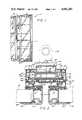
- FIG. 1is perspective of a refrigerator door assembly having a door mounting frame with a mullion in accordance with the present invention
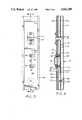
- FIG. 2is an enlarged fragmentary section taken in the plane of line 2--2 in FIG. 1, showing the mullion of the present invention with the free swinging sides of a pair of doors on opposed sides thereof in their closed position;
- FIG. 3is an enlarge partial plan view of a front of the illustrated mullion, showing accessories mounted therein;
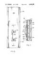
- FIG. 4is a fragmentary vertical section of the illustrated mullion, taken in the plane of line 4--4 in FIG. 3;
- FIG. 5is a fragmentary transverse section of an alternative embodiment of a mullion in accordance with the present invention, with the free-swinging sides of a pair of doors shown in phantom in their closed position on opposed sides of a front side of the mullion;
- FIG. 6is an enlarged partial plan view of a front side of the mullion shown in FIG. 5, showing an accessory mounted thereon;
- FIG. 7is a fragmentary section, taken in the plane of line 7--7 in FIG. 6.
- FIGS. 1-4 of the drawingsthere is shown an illustrative refrigerator door assembly 10, comprising a plurality of insulted glass doors 11 mounted for swinging movement in a door mounting frame 12, which in turn typically is mounted within the opening of a front wall of a refrigerator cabinet or the like. It will be understood that he door assembly 10 is particularly adapted for use in free standing refrigerator or freezer cases or built-in coolers or cabinets of the type used in supermarkets and other retail stores to display refrigerated or frozen merchandise.
- the door mounting frame 12extends about the periphery of the opening in the wall and includes one or more mullions 14 that extend vertically between the top and bottom perimeters of the frame to provide rigidity for the frame 12 and define a sealing surface against which the free swinging sides of the doors 11 engage when in a closed condition.
- the insulated glass doors 11each include an insulated glass unit 15 (FIG. 2), which may be of a known type comprising a plurality of glass panes disposed in parallel side by side relation with a tubular spacer positioned in sealed relation about the perimeter.
- the glass unit 15is supported within an outer metal frame member 18, which preferably is an aluminum extrusion, the frame member 18 defining a rearwardly opening channel 19 and having a front leg 20 positioned in adjacent relation to a front side of the glass unit 15.
- a separate retaining member 21is releasably engageable in the channel 19 of the frame member 18 for retaining a rear side of the glass unit.
- a plastic or other non-metallic, resilient sealing member 22is interposed between the leg 20 of the frame member 18 and the glass unit 15 to provide a seal about the forward peripheral edge of the glass unit.
- a gasket 25is secured to the rear side of each door 11.
- the gasket 25contains magnets 26 for creating a magnetic attraction with a metallic sealing plate or strip 28, preferably made of a metallic or vinyl clad material, mounted on the frame 12 about the periphery of the door opening for defining a sealing and stop surface for the doors.
- the gasket 25is affixed to a carrying plate 27 that is adapted for snap action engagement with the retaining member 21.
- the sealing plate 28 on the front of the mullion 14extends across substantially the width of the mullion so as to provide a sealing surface for doors on both sides thereof, as shown in FIG. 2. Because the sealing plate 28 is highly heat conductive and extends across the ambient air and refrigerated sides of a door mounted gasket engaged therewith, heretofore it has been susceptible to frost buildup.
- each mullionincludes a rigid metallic structural frame member and means for supporting the magnetically attractive sealing plate on the structural frame member in the thermally isolated relation thereto for enhancing the thermal operating efficiency of the mullion.
- the mullion 14includes a first or primary structural frame member 30 which preferably is made of aluminum or other high strength metal and has an elongated hollow section 31 with outwardly extending flanges 32 on opposite sides thereof
- the hollow section 31in this instance is generally rectangular in configuration with the long sides of the rectangle defining forward and rear faces 31', 31", respectively, of the frame member.
- the flanges 32extend outwardly from the hollow section 31 with forward faces thereof in substantial co-planer relation to the forward face 31" of the frame member 30.
- the hollow configuration of the structural frame member 30has been found to enhance the strength and rigidity of the mullion, while the air space defined within the hollow section 31 tends to insulate the forward and rear faces 31', 31" from each other, and thus, enhance the thermal efficiency.
- a non-metallic, generally channel-shaped insulating and retaining member 40is disposed about a front face of the structural frame member 30 for supporting the sealing plate 28 in forwardly spaced relation to the frame member with an air insulating space therebetween.
- the insulating and retaining member 40which may be made of PVC or other substantially rigid plastic material, has a generally C-shaped configuration with a front wall 41 that is substantially co-extensive with the front of the structural frame member 30 and first or inner side walls 42 that extend rearwardly beyond the plane of the rear face 31" of the structural frame member 30.
- the inner side walls 42in this instance are laterally spaced from each other slightly less than the distance between the outer edges of the flanges 32 of the structural frame member 30 and are formed with a pair of inwardly opening channels 43 shown in FIG. 2 adjacent their forward ends for captively receiving the opposed edges of the flanges 32.
- the front wall 41 of the insulating and retaining member 40has a plurality of forwardly extending ribs 44 that support the sealing plate 28 in spaced relation to the front wall 41 of the insulating or retaining member 40 and define a plurality of air spaces therebetween.
- the ribs 44further define longitudinally extending grooves within which one or more electrical heating wires 45 may be positioned and retained.
- electrical heating wires 45are disposed in grooves defined by the ribs 44 at positions adjacent to where the outer peripheral edge of the door mounted sealing gasket 25 engages the sealing plate so as to ensure that the portion of the sealing plate exposed to ambient air for prolonged periods when the doors are closed remain above the dew point temperature of the ambient air.
- the insulating and retaining member 40is formed with second or outer side walls 46 that are coupled to the inner side walls 42 at locations adjacent their rearward ends so as to permit limited pivotal movement of the forward ends thereof.
- the forward ends of the outer side walls 46are formed with opposed inwardly directed channels 48 that can be forced outwardly with the side walls 46, by virtue of the inherent resiliency of the plastic material from which the insulating and retaining member is formed, to permit insertion of peripheral sides 47 of the sealing plate 28 into the channels 48.
- the sides 46snap back to their original position with the channels 48 captively engaging the opposed peripheral sides 47 of the sealing plate 28.
- the sealing plate 28could be assembled into the insulating and retaining member 40 simply by telescopically positioning the sealing plate into the channels 48 of the side walls 46.
- the peripheral sides 47 of the sealing plate 28in this case are recessed inwardly slightly such that the front sealing surface defined by the sealing plate 28 is in substantially the same plane as the forward sides of the channels 48.
- a non-metallic closure member 50is releasably engageable with the rear of the retaining and insulating member 40.
- the illustrated closure plate 50is formed with forwardly facing mounting ribs 51, which in this instance have enlarged generally cylindrical terminal ends.
- the rear terminal ends of the inner and outer side walls 42, 46 of the retaining and insulating member 40define channels 54 with a relatively narrow width entry opening, corresponding substantially to the thickness of the walls of the closure plate mounting ribs 51, but slightly less than the diameter of the cylindrical terminal ends thereof.
- the terminal ends of the mounting ribs 51may be forced through the openings and into the channels 54, with the closure plate thereby being positively retained in mounted position.
- the illustrated closure plate 50has a rearwardly extending central section 56 adapted to facilitate mounting of accessories, as will become apparent.
- the rearwardly extending central section 56has forwardly directed walls 59 for stabilizing the cover plate 50 and maintaining the proper spaced relation of the cover plate 50 with respect to the structural frame member 30.
- a separate inner plastic, insulating plate 60is interposed between the cover plate 50 and the structural frame member 30, which together with the cover plate, defines an air insulating space 62 adjacent the rear side of the structural frame member 30.
- the insulating plate 60includes rearwardly directed flanges 61 for enhancing the rigidity of the assembly. It will be understood that the closure plate 50 and further insulating plate 60 could be formed as a single member.
- the nonmetallic insulating and sealing plate retaining assemblycomprising the plastic retaining member 40, cover plate 50, and insulating plate 60, not only maintains the sealing plate 28 in thermally insulated relation to the metallic structural member 30, but defines an air insulating space which completely surrounds the structural frame member 30.
- the hollow configuration of the structural frame member 30further enhances the thermal efficiency of the mullion.
- the mullion 14further is adapted for supporting commonly used accessories in substantially thermally insulated relation to the metallic structural frame member 30.
- a lock strike plate 70 and an electrical inlet 71are supported on a central forwardly facing side of the sealing plate 28.
- the lock strike plate 70is a conventional metal stamped part having a generally C-shaped configuration with opposed flanges 72 for mounting on the sealing plate 28.
- fastening screws 74each are engageable in respective plastic inserts 75 disposed between the sealing plate 28 and the structural frame member 30.
- the inserts 75are expandable upon threaded engagement by the fasteners 74 for positively retaining the fasteners in their engaged positions.
- the inserts 75also encapsulate the rearwardly extending ends of the fasteners 74 to insulate them from the structural frame member 30.
- a plastic spacer 76preferably also is interposed between the sealing plate 28 and the front wall 41 of the insulating and retaining member 40 for maintaining proper spacing.
- the electrical outlet 71which may be of a known type such as shown in U.S. Pat. No. 4,578,902 assigned to the same assignee as the present application, may similarly be mounted in thermally insulated relation to the structural frame member 30.
- a rearwardly extending cylindrical body portion 80 of the electrical outlet 71 in this instanceextends through oversized apertures 81 in the structural frame member 30 so as to ensure that no metal-to-metal contact exists.
- the mullion 14includes a metallic channel-shaped frame member 85 mounted rearwardly of and in substantially thermally isolated relation to the first or primary structural frame member 30.
- the channel shaped member 85in this instance is generally U-shaped with forwardly directed legs 87 mounted in abutting relation against the rear side of the closure plate 50.
- Mounting studs 86extend through a rear wall 90 of the channel member 85 and cover plate 50 and are affixed to the central structural frame member 30 for secure mounting.
- a plurality of retaining members 88(FIG.
- a vertically extending light fixture 84is mounted on the rear wall 90 of the channel member 85 (FIG. 2). It will be seen that the channel member 85 enables secure mounting of lighting or other fixtures on the rear side of the mullion, while the metallic channel member and accessories are maintained in thermally isolated relation to the primary structural frame member 30 by the cover plate 50.
- the mullion 14aincludes a first or primary structural frame member 30a and a non-metallic, preferably plastic, insulating assembly comprising a generally C-shaped insulating and retaining member 40a and a rear closure plate 50a which completely encapsulate the primary structural frame member 30a and support a sealing plate 28a in thermally isolated relation to a front side of the structural frame member 30a.
- the structural frame member 30a, C-shaped insulating and retaining member 40a, and sealing plate 28aare identical to those previously described.
- the mullion 14aincludes a channel shaped metallic frame member 85a, preferably made of steel, which is rigidly mounted rearwardly of the central structural frame member 30a with the plastic rear cover plate 50a interposed therebetween and forming a thermal barrier between front and rear sides of the mullion.
- the channel frame member 85ahas a rear wall 90a and a pair of forwardly directed legs 87a.
- the legs 87aeach have inwardly turned ends 95 for defining rounded bearing surfaces for engaging the rear closure plate 50a without damage and added strength.
- the rear closure plate 50in this instance is formed with a substantially flat central barrier plate section 60a mounted adjacent the rear face 31"a of the primary structural frame member 30a.
- the barrier plate section 60aextends outwardly in transverse relation to opposed sides of the rear face 31"a of the structural frame member 30a to points in close proximity with the inner side walls 42a of the insulating and retaining member 40a.
- L-shaped walls 58aare formed in rearwardly extending fashion from the barrier plate section 60a for enhancing rigidity of the closure plate 50a and for defining a central rearwardly opening channel 96 within which the channel frame member 85a is mounted.
- Outer ends of the L-shaped legs 58aare formed with forwardly facing mounting ribs 51a that are engageable in respective channels 54a defined by the terminal ends of the inner and outer sidewalls 42a, 46a of the insulating and retaining member 40a.
- a plurality of studs 86aare provided which each have a threaded end 98 adapted for self-threading engagement with an aperture in the rear of the primary structural frame member 30a.
- the studs 86aeach have an integrally formed hex head 99 intermediate their ends. The studs 86a may be threaded into the rear side of the structural frame member 30a until the hex head 99 forces the barrier plate section 60a of the rear closure plate 50a firmly against the rear face 31"a of the frame member 30a.
- the channel frame member 85amay then be positioned within the channel 96 of the closure plate 50a with a rearwardly extended threaded end 100 of each stud 86a extending through a respective mounting aperture in the rear wall 90a of the channel frame member 85 a.
- the channel frame member 85ais rigidly secured in mounted position by retaining nuts 101 that each engage the protruding threaded ends 100 of the studs 86a.
- the primary structural frame member 30a and the channel frame member 85aform a high strength mullion, with the cover plate 50a serving as an effective thermal break between forward and rear sides of the mullion.
- the channel frame member 85aprovides both enhanced structural rigidity for the mullion 14a and reliable mounting of accessories rearwardly of the mullion.
- the mullion 14afurther lends itself to relatively simple assembly, without the usual casting of fluid plastic and subsequent milling typically required in making conventional thermal break frames.
- the mullion 14aincludes means which facilitate rigid, thermally isolated mounting of accessories on a front side thereof.
- a rigid plastic spacer plate 105is provided between the sealing plate 28a and the front wall 41a of the insulating and retaining member 40a and is sized to completely occupy the space between the wire mounting ribs 44a.
- the plastic spacer plate 105is secured to the structural frame member 30a by mounting screws 106 which pass through the spacer plate 105 (FIG. 7), the front wall 41a of the insulating and retaining member 40a, and into threaded engagement with the front wall of the structural frame member 30a.
- a lock plate 70a shown in FIGS. 6 and 7may be rigidly mounted on the front face of the sealing plate 28a by mounting screws 74a directed through the sealing plate 28a and into threaded engagement with the plastic spacer plate 105, the latter of which is securely supported on the structural frame member 30a by its own mounting screws 106. Since neither the plastic spacer plate mounting screws 106, nor the accessory mounting screws 74a are in contact with both the structural frame member 30a and the sealing plate 28a, the accessory and its mounting fasteners are maintained in thermally isolated relation to the structural frame member 30a. As shown in FIG. 7, the plastic spacer plate 105 need not extend the entire length of the mullion, but may be utilized along sections of the mullion where accessories are to be mounted.
- the mullion of the present inventionhas relatively high strength and rigidity while being adapted for condensation free use in commercial refrigerator and freezer units with minimal electrical heating requirements.
- the non-metallic sealing plate mounting assemblynot only securely supports the vinyl clad sealing plate in thermally insulated relation to the metallic structural frame members of the mullion, it further defines a thermal insulating barrier between separate metallic frame sections of the mullion and air insulating spaces adjacent critical areas of the primary structural frame member.
- the mullionhas a relatively simple construction which lends itself to economical manufacture.
Landscapes
- Engineering & Computer Science (AREA)
- Physics & Mathematics (AREA)
- Thermal Sciences (AREA)
- Chemical & Material Sciences (AREA)
- Combustion & Propulsion (AREA)
- Mechanical Engineering (AREA)
- General Engineering & Computer Science (AREA)
- Refrigerator Housings (AREA)
- Devices That Are Associated With Refrigeration Equipment (AREA)
Abstract
Description
Claims (35)
Priority Applications (5)
| Application Number | Priority Date | Filing Date | Title |
|---|---|---|---|
| US07/328,472US4941289A (en) | 1987-12-10 | 1989-03-24 | Refrigerator door frame with insulated mullion |
| NO893349ANO171653C (en) | 1989-03-24 | 1989-08-21 | REFRIGERATOR DEVICE WITH INSULATING SPLASS |
| EP89308710AEP0388550B1 (en) | 1989-03-24 | 1989-08-29 | Refrigerator door frame with insulated mullion |
| DE68913511TDE68913511T2 (en) | 1989-03-24 | 1989-08-29 | Fridge door frame with insulated center post. |
| AU40879/89AAU614913C (en) | 1989-03-24 | 1989-08-29 | Refrigerator door frame with insulated mullion |
Applications Claiming Priority (2)
| Application Number | Priority Date | Filing Date | Title |
|---|---|---|---|
| US07/131,182US4852303A (en) | 1987-12-10 | 1987-12-10 | Refrigerator door frame with insulated mullion |
| US07/328,472US4941289A (en) | 1987-12-10 | 1989-03-24 | Refrigerator door frame with insulated mullion |
Related Parent Applications (1)
| Application Number | Title | Priority Date | Filing Date |
|---|---|---|---|
| US07/131,182Continuation-In-PartUS4852303A (en) | 1987-12-10 | 1987-12-10 | Refrigerator door frame with insulated mullion |
Publications (1)
| Publication Number | Publication Date |
|---|---|
| US4941289Atrue US4941289A (en) | 1990-07-17 |
Family
ID=23281131
Family Applications (1)
| Application Number | Title | Priority Date | Filing Date |
|---|---|---|---|
| US07/328,472Expired - LifetimeUS4941289A (en) | 1987-12-10 | 1989-03-24 | Refrigerator door frame with insulated mullion |
Country Status (4)
| Country | Link |
|---|---|
| US (1) | US4941289A (en) |
| EP (1) | EP0388550B1 (en) |
| DE (1) | DE68913511T2 (en) |
| NO (1) | NO171653C (en) |
Cited By (52)
| Publication number | Priority date | Publication date | Assignee | Title |
|---|---|---|---|---|
| US5161329A (en)* | 1991-12-03 | 1992-11-10 | Brown Noel S | Insulated closure structure |
| US5193310A (en)* | 1991-09-26 | 1993-03-16 | The Standard Products Company | Snap-lock seal retainer |
| US5199273A (en)* | 1990-09-28 | 1993-04-06 | The Manitowoc Company, Inc. | Reach-in cooler with interchangeable refrigerator and freezer systems |
| US5255473A (en)* | 1989-12-11 | 1993-10-26 | Ardco, Inc. | Refrigerator door assembly with stylized substantially all glass front |
| US5284023A (en)* | 1990-09-28 | 1994-02-08 | The Manitowoc Company, Inc. | Reach-in cooler with window |
| US5289657A (en)* | 1992-03-13 | 1994-03-01 | The Standard Products Company | Refrigerator gasket and retainer |
| US5349832A (en)* | 1993-05-14 | 1994-09-27 | Maytag Corporation | Mullion bar assembly with enhanced heat transfer barrier characteristics |
| USD375366S (en) | 1995-10-18 | 1996-11-05 | Dominion Plastics Inc. | Window mullion |
| US5682715A (en)* | 1995-10-30 | 1997-11-04 | General Products Company, Inc. | Two piece center mull for multiple door assembly |
| US5992960A (en)* | 1998-06-12 | 1999-11-30 | Maytag Corporation | Mullion bar retainer arrangement for a refrigerator cabinet |
| US6036294A (en)* | 1997-05-29 | 2000-03-14 | Camco Inc. | Refrigerator mullion |
| US6240703B1 (en) | 1999-03-24 | 2001-06-05 | Cnb Enterprises, Inc. | Insulated closure structure and method |
| WO2001093727A3 (en)* | 2000-06-09 | 2002-03-14 | Anthony Inc | Display case door and frame |
| US20040134128A1 (en)* | 2003-01-10 | 2004-07-15 | Jamison Door Company | Air heated, flexible door panel |
| US6779357B1 (en) | 2003-02-07 | 2004-08-24 | Viking Range Corporation | Mullion shelf assembly |
| US20060090401A1 (en)* | 2003-01-10 | 2006-05-04 | Jamison Door Company | Air heated, flexible door panel |
| US20060152126A1 (en)* | 2005-01-12 | 2006-07-13 | Collins Clint J | Notched mullion retainer arrangement for a refrigerator cabinet |
| US20070022667A1 (en)* | 2005-07-28 | 2007-02-01 | Gemtron Corporation | Product display case door frame having an integrated raceway |
| US20070066739A1 (en)* | 2005-09-16 | 2007-03-22 | General Electric Company | Coated articles of manufacture made of high Tg polymer blends |
| US20070066740A1 (en)* | 2005-09-16 | 2007-03-22 | Odle Roy R | Annular or tubular shaped articles of novel polymer blends |
| US20070066765A1 (en)* | 2005-09-16 | 2007-03-22 | General Electric Company | Polyarlyl ether ketone polymer blends |
| US20070065615A1 (en)* | 2005-09-16 | 2007-03-22 | Odle Roy R | Annular or tubular shaped articles of novel polymer blends |
| US20070066737A1 (en)* | 2005-09-16 | 2007-03-22 | Gallucci Robert R | Flame retardant polymer blends |
| US20070197739A1 (en)* | 2005-09-16 | 2007-08-23 | Ashish Aneja | Poly aryl ether ketone polymer blends |
| US20080165526A1 (en)* | 2005-03-18 | 2008-07-10 | Carrier Corporation | Multiple Door Display Merchandiser With Lighting Enhancement |
| US20080274360A1 (en)* | 2007-05-04 | 2008-11-06 | General Electric Company | Polyaryl ether ketone - polycarbonate copolymer blends |
| US20110011003A1 (en)* | 2005-10-28 | 2011-01-20 | Vogel Lynn D | Flexible door with rigid insulation |
| US20120042666A1 (en)* | 2010-08-19 | 2012-02-23 | General Electric Company | Demand response mullion sweat protection |
| US20130241386A1 (en)* | 2012-03-16 | 2013-09-19 | Samsung Electronics Co., Ltd. | Refrigerator |
| WO2014019625A1 (en)* | 2012-08-02 | 2014-02-06 | Carrier Corporation | Refrigerated sales cabinet |
| WO2014044330A1 (en)* | 2012-09-24 | 2014-03-27 | Carrier Corporation | Refrigerated sales cabinet |
| WO2014030041A3 (en)* | 2012-08-21 | 2014-05-01 | Carrier Corporation | Cabinet body frame for refrigerating cabinet and refrigerating cabinet |
| US20140184049A1 (en)* | 2011-08-24 | 2014-07-03 | Aht Cooling Systems Gmbh | Cooling unit for chilled, in particular frozen, goods |
| US8955271B2 (en) | 2012-09-17 | 2015-02-17 | Steelcase Inc. | Sliding door assembly |
| US9389013B2 (en)* | 2014-08-15 | 2016-07-12 | Anthony International | Thermal frame for a refrigerated enclosure |
| US9400091B2 (en) | 2008-12-19 | 2016-07-26 | Sabic Global Technologies B.V. | Moisture resistant polyimide compositions |
| US9532659B2 (en) | 2015-05-06 | 2017-01-03 | Anthony, Inc. | Sliding door assembly for a refrigerated display case |
| US20170254116A1 (en)* | 2011-09-29 | 2017-09-07 | Invue Security Products Inc. | Cabinet lock for use with programmable electronic key |
| US10295248B2 (en) | 2017-01-09 | 2019-05-21 | Electrolux Home Products, Inc. | Refrigerator with glass door |
| US10590696B2 (en)* | 2018-07-26 | 2020-03-17 | Matrex Window System Inc. | Sill track seal for a window frame |
| US10689899B2 (en) | 2018-10-17 | 2020-06-23 | Matrex Window System Inc. | Gasket railing system for a window frame |
| US10711514B2 (en)* | 2018-07-26 | 2020-07-14 | Matrex Window System Inc. | Male and female gasket coupling for a window frame |
| US10731402B2 (en)* | 2018-07-26 | 2020-08-04 | Matrex Window System Inc. | Jacking screw for adjusting a window frame |
| US20200348072A1 (en)* | 2019-05-01 | 2020-11-05 | Whirlpool Corporation | Construction method for vacuum insulated door |
| US10844651B2 (en) | 2018-07-26 | 2020-11-24 | Matrex Window System Inc. | Compression gasket for sealing a window in a window frame |
| AU2016200099B2 (en)* | 2015-01-07 | 2021-07-01 | Trainnorman Assets Pty Ltd | Refrigeration cabinet |
| US11199045B2 (en)* | 2018-07-26 | 2021-12-14 | Matrex Window System Inc. | Jacking screw for adjusting a window frame |
| US11439253B2 (en)* | 2016-11-28 | 2022-09-13 | Anthony, Inc. | Thermal frame |
| US11684180B2 (en) | 2021-05-21 | 2023-06-27 | Anthony, Inc. | Mullion bracket |
| US11832740B2 (en) | 2021-05-21 | 2023-12-05 | Anthony, Inc. | Thermal frame with insulating backing member |
| US12188293B2 (en) | 2021-05-21 | 2025-01-07 | Anthony, Inc. | Mullion |
| US12203694B2 (en) | 2021-05-21 | 2025-01-21 | Anthony, Inc. | Thermal frame with flange heat input |
Families Citing this family (9)
| Publication number | Priority date | Publication date | Assignee | Title |
|---|---|---|---|---|
| US5113628A (en) | 1990-09-20 | 1992-05-19 | Anthony's Manufacturing Company, Inc. | Railless refrigerator display door |
| USRE35149E (en) | 1990-09-20 | 1996-01-30 | Anthony's Manufacturing Company, Inc. | Railless refrigerator display door |
| US5097642A (en) | 1990-09-20 | 1992-03-24 | Anthony's Manufacturing Company, Inc. | Glass refrigerator door structure |
| ES2121914T3 (en)* | 1992-11-27 | 1998-12-16 | Bosch Siemens Hausgeraete | SEALING GASKET FOR THE DOOR OF A REFRIGERATOR OR FREEZER DEVICE. |
| GB0019596D0 (en) | 2000-08-09 | 2000-09-27 | Foster Refrigerator Uk Ltd | Refrigeration cabinet |
| JP4651333B2 (en)* | 2004-09-07 | 2011-03-16 | 三洋電機株式会社 | Showcase |
| ITRE20050145A1 (en) | 2005-12-23 | 2007-06-24 | Cisaplast Srl | "COUNTERFRAME UNIT-FRAME FOR REFRIGERATOR CABINETS" |
| CN102192634A (en)* | 2010-03-16 | 2011-09-21 | 海信(北京)电器有限公司 | Refrigerator center sill and refrigerator with center sill |
| CN104640482B (en)* | 2012-08-01 | 2019-04-09 | 开利公司 | Freeze sale case |
Citations (3)
| Publication number | Priority date | Publication date | Assignee | Title |
|---|---|---|---|---|
| US3673735A (en)* | 1969-12-31 | 1972-07-04 | Ardco Inc | Glass panel refrigerator door |
| US4815245A (en)* | 1986-10-02 | 1989-03-28 | Josef Gartner & Co. | Thermal-insulating window or facade arrangement in the transparent area |
| US4831780A (en)* | 1987-07-07 | 1989-05-23 | Ardco Inc. | Refrigerator door assembly with thermal break frame |
Family Cites Families (4)
| Publication number | Priority date | Publication date | Assignee | Title |
|---|---|---|---|---|
| US3629972A (en)* | 1970-02-09 | 1971-12-28 | Ardco Inc | Refrigerator door construction |
| US3612821A (en)* | 1970-11-16 | 1971-10-12 | Anthony S Mfg Co | Door frame construction |
| US3697723A (en)* | 1970-12-24 | 1972-10-10 | Ardco Inc | Mullion construction for refrigerator door frame |
| US4260876A (en)* | 1978-12-11 | 1981-04-07 | Anthony's Manufacturing Company, Inc. | Dew point differential power controller |
- 1989
- 1989-03-24USUS07/328,472patent/US4941289A/ennot_activeExpired - Lifetime
- 1989-08-21NONO893349Apatent/NO171653C/enunknown
- 1989-08-29EPEP89308710Apatent/EP0388550B1/ennot_activeExpired - Lifetime
- 1989-08-29DEDE68913511Tpatent/DE68913511T2/ennot_activeExpired - Fee Related
Patent Citations (3)
| Publication number | Priority date | Publication date | Assignee | Title |
|---|---|---|---|---|
| US3673735A (en)* | 1969-12-31 | 1972-07-04 | Ardco Inc | Glass panel refrigerator door |
| US4815245A (en)* | 1986-10-02 | 1989-03-28 | Josef Gartner & Co. | Thermal-insulating window or facade arrangement in the transparent area |
| US4831780A (en)* | 1987-07-07 | 1989-05-23 | Ardco Inc. | Refrigerator door assembly with thermal break frame |
Cited By (77)
| Publication number | Priority date | Publication date | Assignee | Title |
|---|---|---|---|---|
| US5255473A (en)* | 1989-12-11 | 1993-10-26 | Ardco, Inc. | Refrigerator door assembly with stylized substantially all glass front |
| US5199273A (en)* | 1990-09-28 | 1993-04-06 | The Manitowoc Company, Inc. | Reach-in cooler with interchangeable refrigerator and freezer systems |
| US5284023A (en)* | 1990-09-28 | 1994-02-08 | The Manitowoc Company, Inc. | Reach-in cooler with window |
| US5193310A (en)* | 1991-09-26 | 1993-03-16 | The Standard Products Company | Snap-lock seal retainer |
| US5161329A (en)* | 1991-12-03 | 1992-11-10 | Brown Noel S | Insulated closure structure |
| US5289657A (en)* | 1992-03-13 | 1994-03-01 | The Standard Products Company | Refrigerator gasket and retainer |
| US5349832A (en)* | 1993-05-14 | 1994-09-27 | Maytag Corporation | Mullion bar assembly with enhanced heat transfer barrier characteristics |
| USD375366S (en) | 1995-10-18 | 1996-11-05 | Dominion Plastics Inc. | Window mullion |
| US5682715A (en)* | 1995-10-30 | 1997-11-04 | General Products Company, Inc. | Two piece center mull for multiple door assembly |
| US6036294A (en)* | 1997-05-29 | 2000-03-14 | Camco Inc. | Refrigerator mullion |
| US5992960A (en)* | 1998-06-12 | 1999-11-30 | Maytag Corporation | Mullion bar retainer arrangement for a refrigerator cabinet |
| US6240703B1 (en) | 1999-03-24 | 2001-06-05 | Cnb Enterprises, Inc. | Insulated closure structure and method |
| WO2001093727A3 (en)* | 2000-06-09 | 2002-03-14 | Anthony Inc | Display case door and frame |
| US6606833B2 (en) | 2000-06-09 | 2003-08-19 | Anthony, Inc. | Apparatus and methods of forming a display case door and frame |
| US6606832B2 (en) | 2000-06-09 | 2003-08-19 | Anthony, Inc. | Apparatus and methods of forming a display case door and frame |
| US20040134128A1 (en)* | 2003-01-10 | 2004-07-15 | Jamison Door Company | Air heated, flexible door panel |
| US6983565B2 (en)* | 2003-01-10 | 2006-01-10 | Jamison Door Company | Air heated, flexible door panel |
| US20060090401A1 (en)* | 2003-01-10 | 2006-05-04 | Jamison Door Company | Air heated, flexible door panel |
| US6779357B1 (en) | 2003-02-07 | 2004-08-24 | Viking Range Corporation | Mullion shelf assembly |
| US20060152126A1 (en)* | 2005-01-12 | 2006-07-13 | Collins Clint J | Notched mullion retainer arrangement for a refrigerator cabinet |
| US7407240B2 (en) | 2005-01-12 | 2008-08-05 | Whirlpool Corporation | Notched mullion retainer arrangement for a refrigerator cabinet |
| US20080165526A1 (en)* | 2005-03-18 | 2008-07-10 | Carrier Corporation | Multiple Door Display Merchandiser With Lighting Enhancement |
| US7887207B2 (en) | 2005-03-18 | 2011-02-15 | Carrier Corporation | Multiple door display merchandiser with lighting enhancement |
| US20090213579A1 (en)* | 2005-03-18 | 2009-08-27 | Carrier Corporation | Display Merchandiser with Lighting Enhancement |
| US20070022667A1 (en)* | 2005-07-28 | 2007-02-01 | Gemtron Corporation | Product display case door frame having an integrated raceway |
| US20070065615A1 (en)* | 2005-09-16 | 2007-03-22 | Odle Roy R | Annular or tubular shaped articles of novel polymer blends |
| US8945694B2 (en) | 2005-09-16 | 2015-02-03 | Sabic Global Technologies B.V. | Poly aryl ether ketone polymer blends |
| US20070219324A1 (en)* | 2005-09-16 | 2007-09-20 | Ashish Aneja | Poly aryl ether ketone polymer blends |
| US20070066737A1 (en)* | 2005-09-16 | 2007-03-22 | Gallucci Robert R | Flame retardant polymer blends |
| US20070197739A1 (en)* | 2005-09-16 | 2007-08-23 | Ashish Aneja | Poly aryl ether ketone polymer blends |
| US20070066739A1 (en)* | 2005-09-16 | 2007-03-22 | General Electric Company | Coated articles of manufacture made of high Tg polymer blends |
| US20070066765A1 (en)* | 2005-09-16 | 2007-03-22 | General Electric Company | Polyarlyl ether ketone polymer blends |
| US20070066740A1 (en)* | 2005-09-16 | 2007-03-22 | Odle Roy R | Annular or tubular shaped articles of novel polymer blends |
| US8733024B2 (en) | 2005-10-28 | 2014-05-27 | Jamison Door Company | Flexible door with rigid insulation |
| US20110011003A1 (en)* | 2005-10-28 | 2011-01-20 | Vogel Lynn D | Flexible door with rigid insulation |
| US20080274360A1 (en)* | 2007-05-04 | 2008-11-06 | General Electric Company | Polyaryl ether ketone - polycarbonate copolymer blends |
| US9400091B2 (en) | 2008-12-19 | 2016-07-26 | Sabic Global Technologies B.V. | Moisture resistant polyimide compositions |
| US20120042666A1 (en)* | 2010-08-19 | 2012-02-23 | General Electric Company | Demand response mullion sweat protection |
| US9291383B2 (en)* | 2010-08-19 | 2016-03-22 | Clemson University | Demand response mullion sweat protection |
| US9638457B2 (en)* | 2011-08-24 | 2017-05-02 | Aht Cooling Systems Gmbh | Cooling unit for chilled, in particular frozen, goods |
| US20140184049A1 (en)* | 2011-08-24 | 2014-07-03 | Aht Cooling Systems Gmbh | Cooling unit for chilled, in particular frozen, goods |
| US20170254116A1 (en)* | 2011-09-29 | 2017-09-07 | Invue Security Products Inc. | Cabinet lock for use with programmable electronic key |
| US11885155B2 (en)* | 2011-09-29 | 2024-01-30 | Invue Security Products, Inc. | Cabinet lock for use with programmable electronic key |
| US10145604B2 (en) | 2012-03-16 | 2018-12-04 | Samsung Electronics Co., Ltd. | Refrigerator |
| US9752819B2 (en) | 2012-03-16 | 2017-09-05 | Samsung Electronics Co., Ltd. | Refrigerator |
| US9188382B2 (en) | 2012-03-16 | 2015-11-17 | Samsung Electronics Co., Ltd. | Refrigerator |
| US20130241386A1 (en)* | 2012-03-16 | 2013-09-19 | Samsung Electronics Co., Ltd. | Refrigerator |
| WO2014019625A1 (en)* | 2012-08-02 | 2014-02-06 | Carrier Corporation | Refrigerated sales cabinet |
| WO2014030041A3 (en)* | 2012-08-21 | 2014-05-01 | Carrier Corporation | Cabinet body frame for refrigerating cabinet and refrigerating cabinet |
| US9518387B2 (en)* | 2012-09-17 | 2016-12-13 | Steelcase Inc. | Sliding door assembly |
| US8955271B2 (en) | 2012-09-17 | 2015-02-17 | Steelcase Inc. | Sliding door assembly |
| US20150107171A1 (en)* | 2012-09-17 | 2015-04-23 | Steelcase Inc. | Sliding door assembly |
| CN104768428A (en)* | 2012-09-24 | 2015-07-08 | 开利公司 | Refrigerated sales cabinet |
| US9980581B2 (en) | 2012-09-24 | 2018-05-29 | Carrier Corporation | Refrigerated sales cabinet |
| US10285512B2 (en) | 2012-09-24 | 2019-05-14 | Carrier Corporation | Refrigerated sales cabinet |
| WO2014044330A1 (en)* | 2012-09-24 | 2014-03-27 | Carrier Corporation | Refrigerated sales cabinet |
| US9389013B2 (en)* | 2014-08-15 | 2016-07-12 | Anthony International | Thermal frame for a refrigerated enclosure |
| AU2016200099B2 (en)* | 2015-01-07 | 2021-07-01 | Trainnorman Assets Pty Ltd | Refrigeration cabinet |
| US9532659B2 (en) | 2015-05-06 | 2017-01-03 | Anthony, Inc. | Sliding door assembly for a refrigerated display case |
| US11864670B2 (en)* | 2016-11-28 | 2024-01-09 | Anthony, Inc. | Thermal frame |
| US20220361688A1 (en)* | 2016-11-28 | 2022-11-17 | Anthony, Inc. | Thermal frame |
| US11439253B2 (en)* | 2016-11-28 | 2022-09-13 | Anthony, Inc. | Thermal frame |
| US10295248B2 (en) | 2017-01-09 | 2019-05-21 | Electrolux Home Products, Inc. | Refrigerator with glass door |
| US10844651B2 (en) | 2018-07-26 | 2020-11-24 | Matrex Window System Inc. | Compression gasket for sealing a window in a window frame |
| US11199045B2 (en)* | 2018-07-26 | 2021-12-14 | Matrex Window System Inc. | Jacking screw for adjusting a window frame |
| US10731402B2 (en)* | 2018-07-26 | 2020-08-04 | Matrex Window System Inc. | Jacking screw for adjusting a window frame |
| US10711514B2 (en)* | 2018-07-26 | 2020-07-14 | Matrex Window System Inc. | Male and female gasket coupling for a window frame |
| US10590696B2 (en)* | 2018-07-26 | 2020-03-17 | Matrex Window System Inc. | Sill track seal for a window frame |
| US10689899B2 (en) | 2018-10-17 | 2020-06-23 | Matrex Window System Inc. | Gasket railing system for a window frame |
| US11313611B2 (en)* | 2019-05-01 | 2022-04-26 | Whirlpool Corporation | Construction method for vacuum insulated door |
| US20200348072A1 (en)* | 2019-05-01 | 2020-11-05 | Whirlpool Corporation | Construction method for vacuum insulated door |
| US11832740B2 (en) | 2021-05-21 | 2023-12-05 | Anthony, Inc. | Thermal frame with insulating backing member |
| US11684180B2 (en) | 2021-05-21 | 2023-06-27 | Anthony, Inc. | Mullion bracket |
| US12188293B2 (en) | 2021-05-21 | 2025-01-07 | Anthony, Inc. | Mullion |
| US12203694B2 (en) | 2021-05-21 | 2025-01-21 | Anthony, Inc. | Thermal frame with flange heat input |
| US12290187B2 (en) | 2021-05-21 | 2025-05-06 | Anthony, Inc. | Mullion bracket |
| US12383081B2 (en) | 2021-05-21 | 2025-08-12 | Anthony, Inc. | Thermal frame with insulating backing member |
Also Published As
| Publication number | Publication date |
|---|---|
| NO171653C (en) | 1993-04-21 |
| AU614913B2 (en) | 1991-09-12 |
| NO171653B (en) | 1993-01-04 |
| AU4087989A (en) | 1990-09-27 |
| DE68913511T2 (en) | 1994-10-06 |
| NO893349L (en) | 1990-09-25 |
| DE68913511D1 (en) | 1994-04-07 |
| EP0388550B1 (en) | 1994-03-02 |
| NO893349D0 (en) | 1989-08-21 |
| EP0388550A1 (en) | 1990-09-26 |
Similar Documents
| Publication | Publication Date | Title |
|---|---|---|
| US4941289A (en) | Refrigerator door frame with insulated mullion | |
| US4852303A (en) | Refrigerator door frame with insulated mullion | |
| US4891912A (en) | Refrigerator door assembly with multiple gasket sealing arrangement | |
| US4831780A (en) | Refrigerator door assembly with thermal break frame | |
| US5035085A (en) | Refrigerator door assembly with thermal insulated door mounting frame | |
| US5255473A (en) | Refrigerator door assembly with stylized substantially all glass front | |
| US5111618A (en) | Refrigerator door assembly with stylized substantially all glass front | |
| US5024023A (en) | Insulated refrigerator door assembly with substantially all glass front doors | |
| US4998382A (en) | Insulated refrigerator door assembly with substantially all glass front doors | |
| US20010003408A1 (en) | Mullion assembly | |
| US4741127A (en) | Refrigerator door with thermal insulated outer frame | |
| US4948206A (en) | Refrigerator door assembly with decorative front trim panels | |
| US6029411A (en) | Composite door and frame | |
| US9389013B2 (en) | Thermal frame for a refrigerated enclosure | |
| US12290187B2 (en) | Mullion bracket | |
| US6298615B1 (en) | Frame for use with refrigerated enclosure and method of making the same | |
| US12188293B2 (en) | Mullion | |
| AU2013100763B4 (en) | Refrigerator mullion assembly | |
| JPS6238205Y2 (en) | ||
| JPH0645817Y2 (en) | Cold air circulation open showcase partition plate | |
| JP3357727B2 (en) | Articulated showcase | |
| AU2016200099B2 (en) | Refrigeration cabinet | |
| KR950009351Y1 (en) | Condensation prevention device for refrigerator freezer door | |
| KR100572071B1 (en) | Foam panel assembly for storage room | |
| JPH0614881U (en) | Side plate mounting structure for open type refrigerated showcase |
Legal Events
| Date | Code | Title | Description |
|---|---|---|---|
| AS | Assignment | Owner name:ARDCO, INC., A CORP. OF IL, ILLINOIS Free format text:ASSIGNMENT OF ASSIGNORS INTEREST.;ASSIGNOR:ROLEK, MATTHEW;REEL/FRAME:005067/0663 Effective date:19890322 | |
| STCF | Information on status: patent grant | Free format text:PATENTED CASE | |
| CC | Certificate of correction | ||
| FEPP | Fee payment procedure | Free format text:PAYOR NUMBER ASSIGNED (ORIGINAL EVENT CODE: ASPN); ENTITY STATUS OF PATENT OWNER: LARGE ENTITY | |
| FPAY | Fee payment | Year of fee payment:4 | |
| FEPP | Fee payment procedure | Free format text:PAYER NUMBER DE-ASSIGNED (ORIGINAL EVENT CODE: RMPN); ENTITY STATUS OF PATENT OWNER: LARGE ENTITY Free format text:PAYOR NUMBER ASSIGNED (ORIGINAL EVENT CODE: ASPN); ENTITY STATUS OF PATENT OWNER: LARGE ENTITY | |
| FEPP | Fee payment procedure | Free format text:PAYER NUMBER DE-ASSIGNED (ORIGINAL EVENT CODE: RMPN); ENTITY STATUS OF PATENT OWNER: LARGE ENTITY Free format text:PAYOR NUMBER ASSIGNED (ORIGINAL EVENT CODE: ASPN); ENTITY STATUS OF PATENT OWNER: LARGE ENTITY | |
| FPAY | Fee payment | Year of fee payment:8 | |
| FPAY | Fee payment | Year of fee payment:12 | |
| AS | Assignment | Owner name:SUNTRUST BANK, GEORGIA Free format text:ASSIGNMENT OF ASSIGNORS INTEREST;ASSIGNOR:ARDCO HOLDINGS, INC.;REEL/FRAME:012559/0114 Effective date:20020331 | |
| AS | Assignment | Owner name:CARRIER COMMERICAL REFRIGERATION, INC., ILLINOIS Free format text:CHANGE OF NAME;ASSIGNOR:TYLER REFRIGERATION CORPORATION;REEL/FRAME:012785/0657 Effective date:20011231 Owner name:TYLER REFRIGERATION CORPORATION, ILLINOIS Free format text:MERGER;ASSIGNOR:ARDCO, INC.;REEL/FRAME:012785/0661 Effective date:20011212 | |
| AS | Assignment | Owner name:ARDCO HOLDINGS, INC., CALIFORNIA Free format text:ASSIGNMENT OF ASSIGNORS INTEREST;ASSIGNOR:CARRIER COMMERICAL REFRIGATION, INC.;REEL/FRAME:012852/0100 Effective date:20020328 | |
| AS | Assignment | Owner name:TYLER REFRIGERATION CORPORATION, MICHIGAN Free format text:MERGER;ASSIGNOR:ARDCO, INC.;REEL/FRAME:013691/0696 Effective date:20011212 | |
| AS | Assignment | Owner name:CARRIER COMMERCIAL REFRIGERATION, INC., ILLINOIS Free format text:CHANGE OF NAME;ASSIGNOR:TYLER REFRIGERATION CORPORATION;REEL/FRAME:013691/0824 Effective date:20011231 | |
| AS | Assignment | Owner name:MERRILL LYNCH CAPITAL, ILLINOIS Free format text:SECURITY INTEREST;ASSIGNOR:ANTHONY, INC.;REEL/FRAME:015127/0399 Effective date:20040901 | |
| AS | Assignment | Owner name:ANTHONY, INC. (FKA ARDCO HOLDINGS, INC.), CALIFORN Free format text:RELEASE BY SECURED PARTY;ASSIGNOR:GENERAL ELECTRIC CAPITAL CORPORATION, AS AGENT (FKA SUNTRUST BANK, ATLANTA);REEL/FRAME:015147/0939 Effective date:20040901 | |
| AS | Assignment | Owner name:ANTHONY, INC., CALIFORNIA Free format text:MERGER;ASSIGNOR:ARDCO HOLDINGS, INC.;REEL/FRAME:016216/0380 Effective date:20030331 |