US4940457A - Irrigation system for use during arthroscopy - Google Patents
Irrigation system for use during arthroscopyDownload PDFInfo
- Publication number
- US4940457A US4940457AUS07/137,138US13713887AUS4940457AUS 4940457 AUS4940457 AUS 4940457AUS 13713887 AUS13713887 AUS 13713887AUS 4940457 AUS4940457 AUS 4940457A
- Authority
- US
- United States
- Prior art keywords
- fluid
- fluid circuit
- joint
- cannula
- valve assembly
- Prior art date
- Legal status (The legal status is an assumption and is not a legal conclusion. Google has not performed a legal analysis and makes no representation as to the accuracy of the status listed.)
- Expired - Lifetime
Links
Images


Classifications
- A—HUMAN NECESSITIES
- A61—MEDICAL OR VETERINARY SCIENCE; HYGIENE
- A61M—DEVICES FOR INTRODUCING MEDIA INTO, OR ONTO, THE BODY; DEVICES FOR TRANSDUCING BODY MEDIA OR FOR TAKING MEDIA FROM THE BODY; DEVICES FOR PRODUCING OR ENDING SLEEP OR STUPOR
- A61M3/00—Medical syringes, e.g. enemata; Irrigators
- A61M3/02—Enemata; Irrigators
- A61M3/0233—Enemata; Irrigators characterised by liquid supply means, e.g. from pressurised reservoirs
- A61M3/0254—Enemata; Irrigators characterised by liquid supply means, e.g. from pressurised reservoirs the liquid being pumped
- A61M3/0258—Enemata; Irrigators characterised by liquid supply means, e.g. from pressurised reservoirs the liquid being pumped by means of electric pumps
- A—HUMAN NECESSITIES
- A61—MEDICAL OR VETERINARY SCIENCE; HYGIENE
- A61B—DIAGNOSIS; SURGERY; IDENTIFICATION
- A61B1/00—Instruments for performing medical examinations of the interior of cavities or tubes of the body by visual or photographical inspection, e.g. endoscopes; Illuminating arrangements therefor
- A61B1/00112—Connection or coupling means
- A61B1/00119—Tubes or pipes in or with an endoscope
- A—HUMAN NECESSITIES
- A61—MEDICAL OR VETERINARY SCIENCE; HYGIENE
- A61B—DIAGNOSIS; SURGERY; IDENTIFICATION
- A61B1/00—Instruments for performing medical examinations of the interior of cavities or tubes of the body by visual or photographical inspection, e.g. endoscopes; Illuminating arrangements therefor
- A61B1/012—Instruments for performing medical examinations of the interior of cavities or tubes of the body by visual or photographical inspection, e.g. endoscopes; Illuminating arrangements therefor characterised by internal passages or accessories therefor
- A61B1/015—Control of fluid supply or evacuation
- A—HUMAN NECESSITIES
- A61—MEDICAL OR VETERINARY SCIENCE; HYGIENE
- A61B—DIAGNOSIS; SURGERY; IDENTIFICATION
- A61B1/00—Instruments for performing medical examinations of the interior of cavities or tubes of the body by visual or photographical inspection, e.g. endoscopes; Illuminating arrangements therefor
- A61B1/313—Instruments for performing medical examinations of the interior of cavities or tubes of the body by visual or photographical inspection, e.g. endoscopes; Illuminating arrangements therefor for introducing through surgical openings, e.g. laparoscopes
- A61B1/317—Instruments for performing medical examinations of the interior of cavities or tubes of the body by visual or photographical inspection, e.g. endoscopes; Illuminating arrangements therefor for introducing through surgical openings, e.g. laparoscopes for bones or joints, e.g. osteoscopes, arthroscopes
- A—HUMAN NECESSITIES
- A61—MEDICAL OR VETERINARY SCIENCE; HYGIENE
- A61M—DEVICES FOR INTRODUCING MEDIA INTO, OR ONTO, THE BODY; DEVICES FOR TRANSDUCING BODY MEDIA OR FOR TAKING MEDIA FROM THE BODY; DEVICES FOR PRODUCING OR ENDING SLEEP OR STUPOR
- A61M3/00—Medical syringes, e.g. enemata; Irrigators
- A61M3/02—Enemata; Irrigators
- A61M3/0204—Physical characteristics of the irrigation fluid, e.g. conductivity or turbidity
- A61M3/0216—Pressure
- A—HUMAN NECESSITIES
- A61—MEDICAL OR VETERINARY SCIENCE; HYGIENE
- A61M—DEVICES FOR INTRODUCING MEDIA INTO, OR ONTO, THE BODY; DEVICES FOR TRANSDUCING BODY MEDIA OR FOR TAKING MEDIA FROM THE BODY; DEVICES FOR PRODUCING OR ENDING SLEEP OR STUPOR
- A61M2205/00—General characteristics of the apparatus
- A61M2205/33—Controlling, regulating or measuring
- A61M2205/3331—Pressure; Flow
- A61M2205/3344—Measuring or controlling pressure at the body treatment site
- A—HUMAN NECESSITIES
- A61—MEDICAL OR VETERINARY SCIENCE; HYGIENE
- A61M—DEVICES FOR INTRODUCING MEDIA INTO, OR ONTO, THE BODY; DEVICES FOR TRANSDUCING BODY MEDIA OR FOR TAKING MEDIA FROM THE BODY; DEVICES FOR PRODUCING OR ENDING SLEEP OR STUPOR
- A61M3/00—Medical syringes, e.g. enemata; Irrigators
- A61M3/02—Enemata; Irrigators
- A61M3/0202—Enemata; Irrigators with electronic control means or interfaces
Definitions
- the present inventionrelates to an irrigation system for use during arthroscopy so that fluid is communicated to a joint to maintain a selected pressure level within the joint and to maintain a fluid flow as outflow is required.
- an arthroscopeIn arthroscopic surgery, an arthroscope is used to visually inspect a joint, such as a knee or shoulder joint. It is possible to conduct diagnostic testing by viewing tissue, cartilage, etc. within the joint. If surgery is necessary to remove damaged tissue, for example, the arthroscope is used to view the resection of such damaged tissue by a shaver or suction punch well known to those skilled in the art. To assist the arthroscopic surgeon, fluid is communicated to the joint to pressurize the joint and thereby extend or expand the joint to enhance visual inspection. With the joint extended the arthroscope can be more readily orientated within the extended joint to focus on the damaged tissue.
- a fluid circuitis used to communicate fluid from a reservoir to the joint via a control unit.
- the control unitincludes a pump and a pressure transducer which is pressure responsive to control the operation of the pump.
- the fluid circuitis initially a closed loop system such that operation of the pump purges all the air from the fluid circuit and primes the latter with fluid. Thereafter a portion of the fluid circuit is cut to provide two tubular openings, one for fluid inflow and the other for pressure monitoring, and these tubular openings are communicated with the joint.
- fluidis communicated from the reservoir to the joint via an inflow path connected to an inflow cannular or to the arthroscope.
- the pressure monitor lineis normally connected to a pressure monitor cannula. If the inflow path is crimped, restricted, or the arthroscope fluid passage is closed, restricted communication between the reservoir and the joint occurs.
- the pumpoperates in response to the pressure transducer sensing a low pressure level within the joint.
- fluidcommunicates to a safety relief valve with inadequate fluid communication to the joint as desired.
- fluid communicationis lost during arthroscope changes and repositioning because the fluid inflow valve on the arthroscope is normally turned off. This maneuver allows fluid to escape the joint and thus allow air to enter the joint causing vision-impaired air bubbles when the arthroscope is reinserted into the joint.
- a fluid circuit according to the present inventionincludes a monitor check valve assembly (MCV) at the location of the fluid circuit which is to be cut or separated so that one of the two tubular openings provided after such cutting is closed and the other tubular opening is provided with a luer fitting which readily and quickly is attachable to an arthroscope.
- MCVmonitor check valve assembly
- HPBVhigh pressure bleed valve assembly
- the HPBVdefines a support for connecting a first inflow fluid path, a second inflow fluid path, and a pressure monitor line. Under predetermined conditions, the pressure monitor line acts as the second inflow fluid path.
- the first inflow fluid pathcommunicates fluid to the joint and fluid pressure within the joint is communicated to the control unit via the pressure monitor line so that the control unit is capable of measuring the fluid pressure in the joint.
- the HPBVis pressure responsive to open the first inflow fluid path to the second inflow fluid path and communicate fluid to the joint even though the first inflow fluid path may be obstructed downstream from the HPBV.
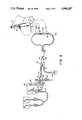
- FIG. 1is a schematic illustration of the fluid circuit of a prior art irrigation system.
- FIG. 2is a schematic illustration of the irrigation system of the present invention.
- FIG. 3is a cross-sectional view of the High Pressure Bleed Valve Assembly illustrated in FIG. 2, and
- FIG. 4is a cross-sectional view of the Monitor Check Valve Assembly illustrated is FIG. 2.
- a pair of bags 10 and 12are filed with the fluid commonly used for irrigation during arthroscopy. These bags communicate via tubing 14 with a pump 16 which is operated by a motor 18 that is controlled by a pressure transducer 20.
- the pump 16, motor 18 and pressure transducer 20comprise a control unit 22 such as described in U.S. Pat. No. 4,635,621 issued to Robert W. Atkinson on Jan. 13, 1987, and assigned to Snyder Laboratories, Inc.
- An outlet tubing 24 from the pump 16communicates fluid to a junction 26 leading to a safety relief valve 28 and to a portion 30.
- the portion 30communicates with a return tubing 32 leading from the portion 30 to the pressure transducer 20.
- a junction 34intersects the tubing 24 and a bleed orifice (not shown) communicates fluid from the tubing 24 to the pressure transducer 20.
- a drain tubing 36is provided at the pressure transducer 20 so that during a prime mode, the pump 16 is operable to fill all of the tubing with fluid from either bag 10 or 12. With all of the air evacuated via drain tube 36 and safety relief valve 28, the drain tubing 36 is closed via hand clamp 38 to maintain fluid in all of the tubing. At that time the portion 30 is cut to attach one cut end to an arthroscope 11, see FIG. 2, or to an inflow cannula and the other cut end to a pressure monitor cannula 13, see FIG. 2, so that arthroscopy of a joint is possible.
- the arthroscope 11includes a stop cock 15 to control fluid flow through the arthroscope. Rotating the stop cock 15 opens and closes an inlet port for the arthroscope.
- FIG. 2Similar components with FIG. 1 include the same reference numerals. Therefore, the fluid bags 10 and 12 communicate with the pump 16 of the control unit 22.
- An outlet tube 40 from the pump 16connects with a junction 42.
- the junction 42is attached to a fitting 44 having a first outlet 46 leading to the pressure transducer 20, a second outlet 48 leading to the drain tube 36 and a third outlet 50 receiving the return tube 52.
- the junction 42intersects two legs of the outlet tube 40; however no communication is provided at the junction 42 between the outlet tube 40 and the pressure transducer 20.
- the outlet tube 40leads to a High Pressure Bleed Valve Assembly (HPBV) 56, as shown more clearly in FIG. 3.
- HPBVHigh Pressure Bleed Valve Assembly
- the HPBV 56includes a first section 58 and a second section 60 securely fastened together to form a plurality of ports or openings for fluid communication.
- the first sectiondefines a first opening 62 communicating with the return tube 52 and a second opening 64 communicating via tube 29 with the safety relief valve 28.
- the safety relief valveis more fully described in U.S. Pat. No. 4,679,596 issued Jul. 14, 1987 to Dan Olson and assigned to Snyder Laboratories.
- a washer 63 disposed in the first opening 62forms an orifice 65 to restrict fluid communication through return tube 52.
- the first section 58further defines a third opening 66 communicating with a tube 68 and a fourth opening 70 receiving a spring 72 and a poppet 74 with a small bleed orifice 76.
- the spring 72biases the poppet to sealingly engage the second section 60.
- the second section 60defines a first opening 80 communicating with the outlet tube 40, a second opening 82 communicating with a tube 84, and a third opening 86 cooperating with the fourth opening 70 of the first section to form a chamber 88 receiving the spring 72 and poppet 74.
- the second sectionforms a T-shaped opening 90 communicating tube 40 with tube 84 while also communicating these tubes with the chamber 88 via poppet 74 and orifice 76.
- the first section 58defines an opening 92, communicating tubes 52, 29 and 68 with the chamber 88.
- a cavity 94 formed by the first section 58provides open communication between openings 62, 64, 66 and 92.
- the tubes 68 and 84lead away from the HPBV 56 to form a loop 96 beyond a clamp 98.
- a Monitor Check Valve Assembly (MCV) 100is included within the loop 96, and is more clearly shown in FIG. 4.
- the MCV 100defines a connector body 102 with a first opening 104 communicating with the end of tube 68.
- a tubular support 106retains open fluid communication at the end of the tube 68.
- the connector body 102forms a spherical membrane 108 with a slit 110 therein.
- the spherical membraneis sufficiently flexible to stretch in the direction of the tube 106 and open slit 110 in response to fluid pressure acting against the concave side of the spherical membrane.
- an outer shoulder 112separates a tubular extension 114 from the part of the connector body 102 forming the spherical membrane 108.
- the tubular extension 114receives a female luer 116 and a male luer 118 cooperates with the luer 116 to form a luer fitting communicating the connector body 102 with the tube 84.
- the control unitWith the irrigation system of the present invention set up in an operating room for arthroscopy of a joint, the control unit is set to a prime mode to evacuate air from the system.
- the clamp 38 and 98are opened and fluid either bag 10 or 12 is communicated from the pump 16 to the tube 40, HPBV 56, tube 84, MCV 100, (the split 110 opens with fluid flow from tube 84 to tube 68) tube 68, HPBV 56 return tube 52, fitting 44 and drain tube 36. Fluid also communicates from the HPBV 56 to the safety relief valve 28 via tube 29.
- a suitable reservoir beneath the end of drain tube 36 and safety relief valve 28collects excess fluid draining from the system when all of the air is evacuated.
- the clamp 38is closed to close the drain tube 36 and the control unit senses fluid pressure within the system via return tube 52 to stop further flow of fluid into the system.
- the surgeoncuts the MCV 100 at the outer shoulder 112.
- the portion of the MCV with the luer fittingforms a first end which is connected to an arthroscope via the male luer 118 after the female luer 116 and remaining tubular extension 114 are separated from the male luer 118.
- the remaining tubular extension 114could be attached to a cannula if an arthroscope inflow is not used.
- the part of the MCV with the spherical membraneforms a second end following the cut. This second end can be neglected during joint diagnosis without leakage of fluid from tube 68 because the spherical membrane 108 closes the slit 110 in response to fluid pressure below a predetermined value acting against the convex side of the sphere.
- the second endis connected to a cannular extending into the joint.
- the cannularbypasses the spherical membrane to retain the latter always open and defines a pressure monitor line.
- the surgeonsets the control unit to the desired pressure level to be maintained in the joint. Therefore, fluid communicated into the joint via tube 84 to pressurize and extend the joint is communicated from the joint via tube 68 to the pressure transducer 20 via HPBV 56 and return tube 52 to control the operation of the pump 16 and maintain the fluid pressure within the joint at the desired or predetermined pressure level.
- the increasing fluid pressure opening poppet 74is communicated to the return tube 52 for communication with the pressure transducer 20 to control operation of the pump 16, as well as communicating with the safety relief valve assembly 28 via cavity 94 and tube 29 to prevent too high a pressure level within the joint.
- the surgeoncan partially close the arthroscope stop cock and provide for dual flow through the arthroscope, albeit restricted, and through the tube 68 with the poppet 74 opened. Moreover, the surgeon can completely close the stop cock on the arthroscope and provide for fluid communication to the joint solely through tube 68.
- the surgeoncan readily and quickly connect an arthroscope and cannula for arthroscopy of a joint with minimal fluid leakage. Moreover the surgeon can control fluid flow to the joint via the arthroscope or via the MCV tube 68, or both.
- the HPBVprioritizes fluid flow to the loop during the prime mode to evacuate the loop of air and the HPBV prioritizes fluid flow to the joint during surgery to maintain a predetermined fluid pressure level within the joint.
Landscapes
- Health & Medical Sciences (AREA)
- Life Sciences & Earth Sciences (AREA)
- Biomedical Technology (AREA)
- Veterinary Medicine (AREA)
- Public Health (AREA)
- General Health & Medical Sciences (AREA)
- Animal Behavior & Ethology (AREA)
- Heart & Thoracic Surgery (AREA)
- Surgery (AREA)
- Engineering & Computer Science (AREA)
- Medical Informatics (AREA)
- Biophysics (AREA)
- Physics & Mathematics (AREA)
- Molecular Biology (AREA)
- Pathology (AREA)
- Optics & Photonics (AREA)
- Nuclear Medicine, Radiotherapy & Molecular Imaging (AREA)
- Radiology & Medical Imaging (AREA)
- Anesthesiology (AREA)
- Hematology (AREA)
- Orthopedic Medicine & Surgery (AREA)
- Physical Education & Sports Medicine (AREA)
- Infusion, Injection, And Reservoir Apparatuses (AREA)
- Endoscopes (AREA)
- External Artificial Organs (AREA)
Abstract
Description
Claims (6)
Priority Applications (11)
| Application Number | Priority Date | Filing Date | Title |
|---|---|---|---|
| US07/137,138US4940457A (en) | 1987-12-23 | 1987-12-23 | Irrigation system for use during arthroscopy |
| CA000576636ACA1297367C (en) | 1987-12-23 | 1988-09-07 | Irrigation system for use during arthroscopy |
| FR8813010AFR2625104B1 (en) | 1987-12-23 | 1988-10-05 | IRRIGATION SYSTEM FOR USE DURING ARTHROSCOPY |
| DE3836487ADE3836487A1 (en) | 1987-12-23 | 1988-10-26 | IRRIGATION SYSTEM FOR USE IN ARTHROSCOPY |
| JP63273372AJPH01171568A (en) | 1987-12-23 | 1988-10-31 | Irrigation apparatus used during arthroscopy |
| IT8823047AIT1227707B (en) | 1987-12-23 | 1988-12-21 | IRRIGATION SYSTEM FOR USE DURING ARTHROSCOPY |
| GB8830016AGB2212066B (en) | 1987-12-23 | 1988-12-22 | Irrigation system for use during arthroscopy |
| AU27409/88AAU629192B2 (en) | 1987-12-23 | 1988-12-22 | Irrigation system for use during arthroscopy |
| GB9115715AGB2245178B (en) | 1987-12-23 | 1991-07-19 | Irrigation system for use during arthroscopy |
| GB9115716AGB2245179B (en) | 1987-12-23 | 1991-07-19 | Irrigation system for use during arthroscopy |
| AU19650/92AAU639861B2 (en) | 1987-12-23 | 1992-07-14 | Irrigation system for use during arthroscopy |
Applications Claiming Priority (1)
| Application Number | Priority Date | Filing Date | Title |
|---|---|---|---|
| US07/137,138US4940457A (en) | 1987-12-23 | 1987-12-23 | Irrigation system for use during arthroscopy |
Publications (1)
| Publication Number | Publication Date |
|---|---|
| US4940457Atrue US4940457A (en) | 1990-07-10 |
Family
ID=22475995
Family Applications (1)
| Application Number | Title | Priority Date | Filing Date |
|---|---|---|---|
| US07/137,138Expired - LifetimeUS4940457A (en) | 1987-12-23 | 1987-12-23 | Irrigation system for use during arthroscopy |
Country Status (8)
| Country | Link |
|---|---|
| US (1) | US4940457A (en) |
| JP (1) | JPH01171568A (en) |
| AU (2) | AU629192B2 (en) |
| CA (1) | CA1297367C (en) |
| DE (1) | DE3836487A1 (en) |
| FR (1) | FR2625104B1 (en) |
| GB (3) | GB2212066B (en) |
| IT (1) | IT1227707B (en) |
Cited By (29)
| Publication number | Priority date | Publication date | Assignee | Title |
|---|---|---|---|---|
| US5152746A (en)* | 1990-04-30 | 1992-10-06 | Zimmer, Inc. | Low pressure irrigation system |
| US5176629A (en)* | 1989-07-31 | 1993-01-05 | C. R. Bard, Inc. | Irrigation system for use with endoscopic procedure |
| US5322506A (en)* | 1989-07-31 | 1994-06-21 | C. R. Bard, Inc. | Irrigation system with high flow bypass for use with endoscopic procedure |
| US5399160A (en)* | 1991-10-04 | 1995-03-21 | Minnesota Mining And Manufacturing Company | Irrigation tubing set having compliant sections |
| US5454784A (en)* | 1994-06-10 | 1995-10-03 | Zimmer, Inc. | Control valve for a fluid set |
| US5464391A (en)* | 1994-03-03 | 1995-11-07 | Northgate Technologies Inc. | Irrigation system for a surgical site |
| US5505707A (en)* | 1994-12-01 | 1996-04-09 | Northgate Technologies, Inc. | Tubing system with pump for delivering continuous fluid flow or fluid bolus to a surgical site |
| USD370727S (en) | 1995-02-28 | 1996-06-11 | Zimmer, Inc. | Cassette for a lavage pump |
| US5554113A (en)* | 1992-06-17 | 1996-09-10 | Storz Endoskop Gmbh | Flow pressure transducer |
| US5605545A (en)* | 1994-05-05 | 1997-02-25 | Northgate Technologies Incorporated | Tubing system for delivering fluid to a surgical site |
| US5626563A (en)* | 1993-01-12 | 1997-05-06 | Minnesota Mining And Manufacturing Company | Irrigation system with tubing cassette |
| US5630799A (en)* | 1991-08-21 | 1997-05-20 | Smith & Nephew Dyonics Inc. | Fluid management system |
| US5647852A (en)* | 1995-01-31 | 1997-07-15 | Zimmer, Inc. | Lavage system including a cassette assembly |
| US5730731A (en)* | 1988-04-28 | 1998-03-24 | Thomas J. Fogarty | Pressure-based irrigation accumulator |
| WO1998006446A3 (en)* | 1996-08-15 | 1998-05-14 | Deka Products Lp | Medical irrigation pump and system |
| US5800383A (en)* | 1996-07-17 | 1998-09-01 | Aquarius Medical Corporation | Fluid management system for arthroscopic surgery |
| US5830180A (en)* | 1996-07-17 | 1998-11-03 | Aquarius Medical Corporation | Fluid management system for arthroscopic surgery |
| US6024720A (en)* | 1995-07-18 | 2000-02-15 | Aquarius Medical Corporation | Fluid management system for arthroscopic surgery |
| US6068617A (en)* | 1992-12-28 | 2000-05-30 | Richmond; Frank M. | Needleless valve for use in intravenous infusion |
| US6371934B1 (en) | 1997-08-06 | 2002-04-16 | C. R. Bard, Inc. | Irrigation system and tip with debrider |
| US6461323B2 (en)* | 2000-05-03 | 2002-10-08 | Reginald H. Fowler | Surgical system pump with flow sensor and method therefor |
| US20030109826A1 (en)* | 2000-05-03 | 2003-06-12 | Conmed Corp. | Surgical system pump and method therefor |
| US20040082898A1 (en)* | 1999-07-29 | 2004-04-29 | Jean-Marie Mathias | Biological sample device receiver |
| US20060266423A1 (en)* | 2005-05-25 | 2006-11-30 | Fujinon Corporation | Water feeding device for endoscope |
| US20070106230A1 (en)* | 2005-10-21 | 2007-05-10 | Duane Kelloway | Multi-prong connector, system and method of use |
| US20070239113A1 (en)* | 2006-04-06 | 2007-10-11 | Reznik Alan M | Arthroscopic fluid control device |
| US20100324473A1 (en)* | 2006-04-06 | 2010-12-23 | Reznik Alan M | Arthroscopic fluid control device and method for controlling fluid flow in arthroscopic procedures |
| US20120130310A1 (en)* | 2010-10-05 | 2012-05-24 | W.O.M. World Of Medicine Ag | Joint pressure measurement with sensor in the drainage line |
| US8814829B2 (en) | 2010-08-12 | 2014-08-26 | Baxter International Inc. | Drug delivery device for fluid restricted patients |
Citations (9)
| Publication number | Priority date | Publication date | Assignee | Title |
|---|---|---|---|---|
| US274447A (en)* | 1883-03-20 | William-kentish | ||
| US4461281A (en)* | 1977-06-15 | 1984-07-24 | Carson Robert W | Arthroscopic surgical apparatus and method |
| US4535818A (en)* | 1983-09-26 | 1985-08-20 | Vernay Laboratories, Inc. | Valve assembly |
| US4555645A (en)* | 1982-12-01 | 1985-11-26 | Snyder Laboratories, Inc. | Moveable coil linear motor |
| US4561431A (en)* | 1982-12-01 | 1985-12-31 | Snyder Laboratories, Inc. | Lavage system with linear motor |
| US4635621A (en)* | 1982-12-01 | 1987-01-13 | Snyder Laboratories, Inc. | Lavage system with replaceable pump |
| US4650461A (en)* | 1985-06-10 | 1987-03-17 | Woods Randall L | Extracapasular cortex irrigation and extraction |
| US4662871A (en)* | 1984-09-18 | 1987-05-05 | Stephen Rafelson | Disposable suction catheter and system for providing multiple suctioning capabilities during medical procedures or the like |
| US4671786A (en)* | 1982-09-22 | 1987-06-09 | C. R. Bard, Inc. | Overpressure safety valve |
Family Cites Families (4)
| Publication number | Priority date | Publication date | Assignee | Title |
|---|---|---|---|---|
| US3889675A (en)* | 1974-06-25 | 1975-06-17 | Stewart Research | Suction-irrigator |
| SE438962B (en)* | 1983-05-18 | 1985-05-28 | Gambro Crafon Ab | BODY RINSE RINSE SYSTEM |
| US4604089A (en)* | 1983-08-15 | 1986-08-05 | Codman & Shurtleff, Inc. | Pressure regulated irrigation system for arthroscopy |
| DE3338758C2 (en)* | 1983-10-21 | 1986-09-11 | Hubert Dipl.-Ing. 1000 Berlin Fuchs | Device for the perfusion of body cavities with a liquid |
- 1987
- 1987-12-23USUS07/137,138patent/US4940457A/ennot_activeExpired - Lifetime
- 1988
- 1988-09-07CACA000576636Apatent/CA1297367C/ennot_activeExpired - Fee Related
- 1988-10-05FRFR8813010Apatent/FR2625104B1/ennot_activeExpired - Fee Related
- 1988-10-26DEDE3836487Apatent/DE3836487A1/ennot_activeCeased
- 1988-10-31JPJP63273372Apatent/JPH01171568A/enactivePending
- 1988-12-21ITIT8823047Apatent/IT1227707B/enactive
- 1988-12-22GBGB8830016Apatent/GB2212066B/ennot_activeExpired - Lifetime
- 1988-12-22AUAU27409/88Apatent/AU629192B2/ennot_activeCeased
- 1991
- 1991-07-19GBGB9115715Apatent/GB2245178B/ennot_activeExpired - Lifetime
- 1991-07-19GBGB9115716Apatent/GB2245179B/ennot_activeExpired - Lifetime
- 1992
- 1992-07-14AUAU19650/92Apatent/AU639861B2/ennot_activeCeased
Patent Citations (9)
| Publication number | Priority date | Publication date | Assignee | Title |
|---|---|---|---|---|
| US274447A (en)* | 1883-03-20 | William-kentish | ||
| US4461281A (en)* | 1977-06-15 | 1984-07-24 | Carson Robert W | Arthroscopic surgical apparatus and method |
| US4671786A (en)* | 1982-09-22 | 1987-06-09 | C. R. Bard, Inc. | Overpressure safety valve |
| US4555645A (en)* | 1982-12-01 | 1985-11-26 | Snyder Laboratories, Inc. | Moveable coil linear motor |
| US4561431A (en)* | 1982-12-01 | 1985-12-31 | Snyder Laboratories, Inc. | Lavage system with linear motor |
| US4635621A (en)* | 1982-12-01 | 1987-01-13 | Snyder Laboratories, Inc. | Lavage system with replaceable pump |
| US4535818A (en)* | 1983-09-26 | 1985-08-20 | Vernay Laboratories, Inc. | Valve assembly |
| US4662871A (en)* | 1984-09-18 | 1987-05-05 | Stephen Rafelson | Disposable suction catheter and system for providing multiple suctioning capabilities during medical procedures or the like |
| US4650461A (en)* | 1985-06-10 | 1987-03-17 | Woods Randall L | Extracapasular cortex irrigation and extraction |
Non-Patent Citations (5)
| Title |
|---|
| 3M Operators Manual 3M Arthroscopy Pump (1986).* |
| 3M Surgeon s Guide 3M Arthroscopy Pump (1986).* |
| 3M Surgeon's Guide 3M Arthroscopy Pump (1986). |
| Orthopaedic Products Technical Bulletin #110 3M (3-1987). |
| Orthopaedic Products Technical Bulletin 110 3M (3 1987).* |
Cited By (46)
| Publication number | Priority date | Publication date | Assignee | Title |
|---|---|---|---|---|
| US5730731A (en)* | 1988-04-28 | 1998-03-24 | Thomas J. Fogarty | Pressure-based irrigation accumulator |
| US5176629A (en)* | 1989-07-31 | 1993-01-05 | C. R. Bard, Inc. | Irrigation system for use with endoscopic procedure |
| US5322506A (en)* | 1989-07-31 | 1994-06-21 | C. R. Bard, Inc. | Irrigation system with high flow bypass for use with endoscopic procedure |
| US5152746A (en)* | 1990-04-30 | 1992-10-06 | Zimmer, Inc. | Low pressure irrigation system |
| US5882339A (en)* | 1991-08-21 | 1999-03-16 | Smith & Nephew, Inc. | Fluid management system |
| US5840060A (en)* | 1991-08-21 | 1998-11-24 | Smith & Nephew, Inc. | Fluid management system |
| US5643203A (en)* | 1991-08-21 | 1997-07-01 | Smith & Nephew Dyonics Inc. | Fluid management system |
| US5630799A (en)* | 1991-08-21 | 1997-05-20 | Smith & Nephew Dyonics Inc. | Fluid management system |
| US5630798A (en)* | 1991-08-21 | 1997-05-20 | Smith & Nephew Dyonics Inc. | Fluid management system |
| US5643302A (en)* | 1991-08-21 | 1997-07-01 | Smith & Nephew Dyonics Inc. | Fluid management system |
| US5399160A (en)* | 1991-10-04 | 1995-03-21 | Minnesota Mining And Manufacturing Company | Irrigation tubing set having compliant sections |
| US5554113A (en)* | 1992-06-17 | 1996-09-10 | Storz Endoskop Gmbh | Flow pressure transducer |
| US6068617A (en)* | 1992-12-28 | 2000-05-30 | Richmond; Frank M. | Needleless valve for use in intravenous infusion |
| US5626563A (en)* | 1993-01-12 | 1997-05-06 | Minnesota Mining And Manufacturing Company | Irrigation system with tubing cassette |
| US5464391A (en)* | 1994-03-03 | 1995-11-07 | Northgate Technologies Inc. | Irrigation system for a surgical site |
| US5605545A (en)* | 1994-05-05 | 1997-02-25 | Northgate Technologies Incorporated | Tubing system for delivering fluid to a surgical site |
| US5454784A (en)* | 1994-06-10 | 1995-10-03 | Zimmer, Inc. | Control valve for a fluid set |
| US5505707A (en)* | 1994-12-01 | 1996-04-09 | Northgate Technologies, Inc. | Tubing system with pump for delivering continuous fluid flow or fluid bolus to a surgical site |
| US5647852A (en)* | 1995-01-31 | 1997-07-15 | Zimmer, Inc. | Lavage system including a cassette assembly |
| USD370727S (en) | 1995-02-28 | 1996-06-11 | Zimmer, Inc. | Cassette for a lavage pump |
| US6024720A (en)* | 1995-07-18 | 2000-02-15 | Aquarius Medical Corporation | Fluid management system for arthroscopic surgery |
| US5800383A (en)* | 1996-07-17 | 1998-09-01 | Aquarius Medical Corporation | Fluid management system for arthroscopic surgery |
| US5830180A (en)* | 1996-07-17 | 1998-11-03 | Aquarius Medical Corporation | Fluid management system for arthroscopic surgery |
| WO1998006446A3 (en)* | 1996-08-15 | 1998-05-14 | Deka Products Lp | Medical irrigation pump and system |
| US6077246A (en)* | 1996-08-15 | 2000-06-20 | Deka Products Limited Partnership | Medical irrigation pump and system |
| US6436072B1 (en) | 1996-08-15 | 2002-08-20 | Deka Products Limited Partnership | Medical irrigation pump and system |
| US7070574B2 (en) | 1997-08-06 | 2006-07-04 | C.R. Bard, Inc. | Irrigation system and tip with debrider |
| US6371934B1 (en) | 1997-08-06 | 2002-04-16 | C. R. Bard, Inc. | Irrigation system and tip with debrider |
| US20020082557A1 (en)* | 1997-08-06 | 2002-06-27 | Jackson Robert W. | Irrigation system and tip with debrider |
| US7435231B2 (en) | 1999-07-29 | 2008-10-14 | Fenwal, Inc. | Biological sample device receiver |
| US20040082898A1 (en)* | 1999-07-29 | 2004-04-29 | Jean-Marie Mathias | Biological sample device receiver |
| US6461323B2 (en)* | 2000-05-03 | 2002-10-08 | Reginald H. Fowler | Surgical system pump with flow sensor and method therefor |
| US6899697B2 (en) | 2000-05-03 | 2005-05-31 | Conmed Corp. | Surgical system pump and method therefor |
| US20030109826A1 (en)* | 2000-05-03 | 2003-06-12 | Conmed Corp. | Surgical system pump and method therefor |
| US20060266423A1 (en)* | 2005-05-25 | 2006-11-30 | Fujinon Corporation | Water feeding device for endoscope |
| EP1726255A3 (en)* | 2005-05-25 | 2007-01-03 | Fujinon Corporation | Water feeding device for an endoscope |
| EP1836951A2 (en) | 2005-05-25 | 2007-09-26 | Fujinon Corporation | Water feeding device for an endoscope |
| EP1836951A3 (en)* | 2005-05-25 | 2007-10-10 | Fujinon Corporation | Water feeding device for an endoscope |
| US20070106230A1 (en)* | 2005-10-21 | 2007-05-10 | Duane Kelloway | Multi-prong connector, system and method of use |
| US20070239113A1 (en)* | 2006-04-06 | 2007-10-11 | Reznik Alan M | Arthroscopic fluid control device |
| US7785287B2 (en) | 2006-04-06 | 2010-08-31 | Reznik Alan M | Arthroscopic fluid control device |
| US20100324473A1 (en)* | 2006-04-06 | 2010-12-23 | Reznik Alan M | Arthroscopic fluid control device and method for controlling fluid flow in arthroscopic procedures |
| US8075520B2 (en) | 2006-04-06 | 2011-12-13 | Reznik Alan M | Arthroscopic fluid control device and method for controlling fluid flow in arthroscopic procedures |
| US8814829B2 (en) | 2010-08-12 | 2014-08-26 | Baxter International Inc. | Drug delivery device for fluid restricted patients |
| US20120130310A1 (en)* | 2010-10-05 | 2012-05-24 | W.O.M. World Of Medicine Ag | Joint pressure measurement with sensor in the drainage line |
| EP2438934B1 (en)* | 2010-10-05 | 2015-12-16 | W.O.M. World of Medicine GmbH | Joint pressure measurement with sensor in the drainage conduit |
Also Published As
| Publication number | Publication date |
|---|---|
| AU639861B2 (en) | 1993-08-05 |
| AU629192B2 (en) | 1992-10-01 |
| GB2212066B (en) | 1992-04-15 |
| FR2625104B1 (en) | 1994-02-11 |
| AU1965092A (en) | 1992-09-17 |
| IT8823047A0 (en) | 1988-12-21 |
| GB2245178B (en) | 1992-04-15 |
| FR2625104A1 (en) | 1989-06-30 |
| GB9115716D0 (en) | 1991-09-04 |
| GB8830016D0 (en) | 1989-02-15 |
| AU2740988A (en) | 1989-06-29 |
| JPH01171568A (en) | 1989-07-06 |
| CA1297367C (en) | 1992-03-17 |
| GB2245179A (en) | 1992-01-02 |
| IT1227707B (en) | 1991-04-23 |
| GB2245179B (en) | 1992-04-29 |
| GB9115715D0 (en) | 1991-09-04 |
| DE3836487A1 (en) | 1989-07-13 |
| GB2212066A (en) | 1989-07-19 |
| GB2245178A (en) | 1992-01-02 |
Similar Documents
| Publication | Publication Date | Title |
|---|---|---|
| US4940457A (en) | Irrigation system for use during arthroscopy | |
| US5454784A (en) | Control valve for a fluid set | |
| US5707356A (en) | Pressure relief valve | |
| US4886498A (en) | Mechanism for coupling the aspirant line of an irrigation/aspiration machine to the pressure monitoring section | |
| US4671786A (en) | Overpressure safety valve | |
| US4502502A (en) | Overpressure safety valve | |
| US5823986A (en) | Perfusion system | |
| US4714464A (en) | Mechanism for coupling the aspirant line of an irrigation/aspiration machine to the pressure monitoring section | |
| US5401255A (en) | Multi-functional valve with unitary valving member and improved safety | |
| CN104728454B (en) | Normally closed valve in a free state | |
| US4704106A (en) | Drainage device with diverted gas flow path | |
| WO1996024397A9 (en) | Perfusion system | |
| US5643191A (en) | Cardioplegia delivery system and method for converting from warm cardioplegia to cold cardioplegia | |
| JPS63500432A (en) | ▲Irrigation▼Injection system | |
| CA2195360A1 (en) | Intravenous filter device | |
| CN101124009A (en) | Medical apparatus and method of use thereof | |
| US4469484A (en) | Surgical drainage device with automatic negative pressure relief system | |
| DE4219888A1 (en) | Medical throughflow pressure transducer for insufflation system - contains sterilisable pressure membrane, non-sterilised transducer and over-pressure valve | |
| JPS58209359A (en) | Apparatus for discharging liquid in abdominal cavity | |
| US11883570B2 (en) | Blood transfusion kit and system and method | |
| JP2542728B2 (en) | Dialysis machine unit | |
| JPS61502659A (en) | Device for flushing body cavities | |
| US20020103458A1 (en) | Continous irrigation y-tubing control valve device and system | |
| EP0112641B1 (en) | Drainage device with diverted gas flow path | |
| EP1502167B1 (en) | System, method and apparatus for regulating vacuum supplied to surgical tools |
Legal Events
| Date | Code | Title | Description |
|---|---|---|---|
| AS | Assignment | Owner name:SNYDER LABORATORIES, INC., 200 W. OHIO AVENUE, P.O Free format text:ASSIGNMENT OF ASSIGNORS INTEREST.;ASSIGNOR:OLSON, DANIEL H.;REEL/FRAME:004806/0800 Effective date:19871216 Owner name:SNYDER LABORATORIES, INC., 200 W. OHIO AVENUE, P.O Free format text:ASSIGNMENT OF ASSIGNORS INTEREST;ASSIGNOR:OLSON, DANIEL H.;REEL/FRAME:004806/0800 Effective date:19871216 | |
| STCF | Information on status: patent grant | Free format text:PATENTED CASE | |
| FPAY | Fee payment | Year of fee payment:4 | |
| FPAY | Fee payment | Year of fee payment:8 | |
| FEPP | Fee payment procedure | Free format text:PAYOR NUMBER ASSIGNED (ORIGINAL EVENT CODE: ASPN); ENTITY STATUS OF PATENT OWNER: LARGE ENTITY | |
| FPAY | Fee payment | Year of fee payment:12 | |
| REMI | Maintenance fee reminder mailed | ||
| AS | Assignment | Owner name:ZIMMER, INC., INDIANA Free format text:ASSIGNMENT OF ASSIGNORS INTEREST;ASSIGNOR:BRISTOL-MYERS SQUIBB COMPANY;REEL/FRAME:012729/0494 Effective date:20020114 | |
| AS | Assignment | Owner name:ZIMMER ORTHOPAEDIC SURGICAL PRODUCTS, INC., OHIO Free format text:ASSIGNMENT OF ASSIGNORS INTEREST;ASSIGNOR:ZIMMER, INC.;REEL/FRAME:013845/0422 Effective date:20020628 |