US4940099A - Cutting elements for roller cutter drill bits - Google Patents
Cutting elements for roller cutter drill bitsDownload PDFInfo
- Publication number
- US4940099A US4940099AUS07/333,576US33357689AUS4940099AUS 4940099 AUS4940099 AUS 4940099AUS 33357689 AUS33357689 AUS 33357689AUS 4940099 AUS4940099 AUS 4940099A
- Authority
- US
- United States
- Prior art keywords
- cutting
- inserts
- cutting inserts
- generally
- wear
- Prior art date
- Legal status (The legal status is an assumption and is not a legal conclusion. Google has not performed a legal analysis and makes no representation as to the accuracy of the status listed.)
- Expired - Lifetime
Links
Images
Classifications
- E—FIXED CONSTRUCTIONS
- E21—EARTH OR ROCK DRILLING; MINING
- E21B—EARTH OR ROCK DRILLING; OBTAINING OIL, GAS, WATER, SOLUBLE OR MELTABLE MATERIALS OR A SLURRY OF MINERALS FROM WELLS
- E21B10/00—Drill bits
- E21B10/46—Drill bits characterised by wear resisting parts, e.g. diamond inserts
- E21B10/56—Button-type inserts
- E21B10/567—Button-type inserts with preformed cutting elements mounted on a distinct support, e.g. polycrystalline inserts
- E21B10/5673—Button-type inserts with preformed cutting elements mounted on a distinct support, e.g. polycrystalline inserts having a non planar or non circular cutting face
- E—FIXED CONSTRUCTIONS
- E21—EARTH OR ROCK DRILLING; MINING
- E21B—EARTH OR ROCK DRILLING; OBTAINING OIL, GAS, WATER, SOLUBLE OR MELTABLE MATERIALS OR A SLURRY OF MINERALS FROM WELLS
- E21B10/00—Drill bits
- E21B10/08—Roller bits
- E21B10/16—Roller bits characterised by tooth form or arrangement
- E—FIXED CONSTRUCTIONS
- E21—EARTH OR ROCK DRILLING; MINING
- E21B—EARTH OR ROCK DRILLING; OBTAINING OIL, GAS, WATER, SOLUBLE OR MELTABLE MATERIALS OR A SLURRY OF MINERALS FROM WELLS
- E21B10/00—Drill bits
- E21B10/46—Drill bits characterised by wear resisting parts, e.g. diamond inserts
- E21B10/50—Drill bits characterised by wear resisting parts, e.g. diamond inserts the bit being of roller type
- E21B10/52—Drill bits characterised by wear resisting parts, e.g. diamond inserts the bit being of roller type with chisel- or button-type inserts
Definitions
- This inventionrelates to roller cutter drill bits used primarily in drilling wells for oil, gas, or geothermal energy, and more particularly to the cutting elements used on the roller cutters.
- the prior arthas attempted to minimize these problems by fabricating the cutting inserts from abrasion resistant grades of tungsten carbide.
- the grade of tungsten carbide selecteddepends on the formation to be cut, and the drilling conditions encountered. Inserts having a high abrasion resistance are typically harder and will have a greater wear life but are more brittle and thus more susceptible to fracture when drilling in hard tough formations, while inserts having a tougher grade of carbide are relatively soft and will have less wear resistance.
- a compromiseis generally made using a grade of tungsten carbide which is as hard as possible but will not fracture when hard tough formations are encountered.
- the hard tough formationsare encountered only occasionally, usually in a shallow layer or in nodules of formations. This is commonly referred to as hitting a "hard streak”. Because of these "hard streaks" in the formations encountered, occasionally a tougher less abrasive resistant cutting insert is generally employed. If it were not for these occasional "hard streaks" a harder more abrasive resistant insert could be used and less insert wear would occur.
- a rock bitusually encounters stratas of abrasive and non-abrasive formations, as in the typical case of sand and shale sections.
- the degree of abrasive formation encounteredwill control the rate at which the inserts wear and since the inserts in the same annular row on the roller cutter are of generally the same hardness the wear will occur at roughly equal rates for all of the inserts in the row.
- their cutting efficiencybecomes diminished, causing the drilling rate to decrease which will generally control the time at which the bit is replaced with a new sharp bit.
- Prior art drill bitshave disclosed composite inserts, using multiple grades of tungsten carbide in the fabrication of inserts in an attempt to create an abrasive resistant tough insert to reduce the wear or dulling of the insert cutting surface while maintaining toughness to prevent fracture.
- Prior art drill bits having cutting elements or inserts formed of multiple grades of tungsten carbidereference is made to U.S. Pat. Nos. 4,705,124; 4,722,405; and 4,694,918.
- Such prior artdiscloses cutting inserts in which the cutting surface uses a harder grade of tungsten carbide and grades to a softer material, or has a diamond layer for increased hardness.
- Also shownare cutting inserts formed of different grades of tungsten carbide material with the leading face of the insert using a softer tougher grade of tungsten carbide and the trailing face having a harder grade of tungsten carbide.
- the present inventionis particularly directed to a roller cutter drill bit in which the roller cutters have a plurality of cutting elements thereon arranged in a plurality of concentric annular rows.
- Each roller cutterhas a generally frusto-conical body with a plurality of generally cylindrically shaped mounting sockets or openings therein which receive individual cutting elements or inserts for securing or mounting the cutting inserts on the body.
- the cutting insertshave outer projecting tips for engaging the formation in which the bore hole is drilled.
- At least the projecting tips of the cutting insertsare formed of a wear-resistant material and the projecting tips of at least 20% to 50% of the cutting inserts in at least one row are formed of a substantially harder wear-resistant material than the cutting tips of the remaining cutting inserts in such rows and are intermingled in a generally uniformly spaced predetermined pattern with the remaining cutting inserts.
- the cutting tips of the remaining cutting insertshave a wear-resistant material which is substantially tougher but softer than the tips of the other cutting inserts.
- Cutting inserts for roller cuttershave generally cylindrical bodies which fit within receiving sockets within the roller cutter body but the projecting tips have various shapes and various projecting lengths depending primarily on the type of formation to be encountered. Normally, relatively short length rounded tips are used in drilling the hardest formations while relatively long chisel-shaped tips are used in drilling of softer formations. Conically-shaped tips are utilized in various formations and particularly medium hardness formations.
- the cutting inserts of the present inventionwhich have cutting surfaces of a harder material may have a blunter shape which is less susceptible to fracture than the more aggressive sharper shapes used in the inserts having softer tougher cutting surfaces.
- the hard cutting insertsmay be either formed of a hard homogeneous material, or formed of a hard cutting surface with the remainder of the insert being of a softer tougher material.
- Several transition layersmay be provided, if desired, between the hard outer cutting surface and the softer material of the body of the cutting insert.
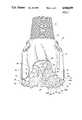
- FIG. 1is a perspective of a roller cutter drill bit comprising the present invention in which selected cutting inserts have tips of a harder wear-resistant material than the tips of the remaining cutting inserts and are intermingled with the remaining cutting inserts in a generally uniformly spaced predetermined pattern;
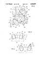
- FIG. 2is an enlarged sectional view of a roller cutter shown in FIG. 1 mounted on a journal for rotation and having a plurality of cutting inserts comprising the present invention thereon;
- FIG. 3is an enlarged sectional view of two adjacent cutting inserts in a row with the projecting tips of the cutting inserts formed of different hardnesses and having different shapes;
- FIG. 4is an enlarged sectional view of two modified adjacent cutting inserts in a row with the projecting tips of the cutting inserts formed of different hardnesses and having different shapes.
- a roller cutter drill bit in accordance with this inventionis shown at 10 and has a main bit body 12 with an upwardly extending threaded pin 14 adapted to be connected to a drill string for rotation.
- Main body 12is formed from three integral lugs to define an upper shank 15 below pin 14 and three downwardly extending legs 16.
- Each leg 16has a journal 18 on its extending end and a roller cutter generally designated 20 is mounted for rotation on journal 18 about bushing 21, ball bearings 22, and end thrust bearing 24.
- Lubricantis supplied to the bearing areas from a lubricant supply (not shown) through lubricant channels 26.
- a retainer 27is positioned adjacent ball bearings 22 for holding bearings 22 in position.
- a nozzle indicated generally at 28is provided at the juncture of adjacent legs 16 and a stream of pressurized drilling fluid is discharged therefrom at an angled relation relative to the rotational axis of bit 10 for first impinging against a leading roller cutter 20, and then the bottom of the bore hole for scouring the bore hole bottom immediately in advance of leading roller cutter 20 engaging the formation in a cutting action.
- Roller cutter 20has a frusto-conical body 30 with cutting elements or inserts arranged thereon in a plurality of concentric annular rows indicated at 32A, 32B, 32C and 32D.
- Row 32Ais a reaming insert row or so-called "G" row and includes a plurality of cylindrical cutting inserts or discs 34 and 36 which are secured by press fitting within similarly shaped sockets 35 in body 30 so that a substantially flush outer cutting face 37 is provided with the outer surface of body 30 for engaging the side wall surface of the bore hole and extending in a plane generally at right angles to the bottom of the bore hole.
- Inserts 34are formed of tungsten carbide and inserts 36 have a tungsten carbide body with the outer cutting face of the body having a diamond layer, such as a polycrystalline diamond layer having a thickness of 300 microns.
- the cutting surfaces of inserts 36have a wear resistance material thereon of a hardness substantially greater than the hardness of the cutting surfaces of tungsten carbide inserts 34.
- inserts 36formed of tungsten carbide of a harder grade such as 1700 DPH (diamond pyramid hardness with a 10KG indentor), than the tungsten carbide from which inserts 34 are formed in order to provide increased hardness.
- Inserts 34may be formed, for example, of a softer but tougher grade of tungsten carbide, such as 1200 DPH.
- inserts 34may be formed of Firth Sterling grade H-71 of tunsten carbide while inserts 36 may be formed of Firth Sterling grade H-6 of tungsten carbide. Inserts 34 and 36 are illustrated in row 32A of FIG. 1 in an alternating pattern in equal numbers with inserts 34 defining alternate inserts and inserts 36 defining intervening inserts. Row 32A maintains the gage or diameter of the bore hole along with the adjacent gage row 32B.
- FIG. 3which is the so-called "gage" row, cutting inserts are illustrated in an alternating pattern comprising alternate inserts 38 and the remaining intervening inserts 40.
- an alternate insert 38is shown adjacent an intervening insert 40.
- Alternate insert 38has a cylindrical body 42 and a projecting end or tip 44 extending outwardly from the outer surface 45 of a cutter body 30.
- the end of tip 44is rounded and formed of a hard grade tungsten carbide to provide a hard cutting surface for engaging relatively hard formations.
- the major portion of the length of cylindrical body 42is received within a generally cylindrical receiving socket 46 in which insert 38 is press fitted.
- Cutting insert 38projects a length L from outer surface 45 of cutter body 12 as shown in FIG. 3.
- Cutting insert 38is formed of an outer rounded tip 44 which provides a cutting surface. Insert 40 has a chisel-like projecting end or tip 46 forming an outer cutting edge 48. Cutting insert 40 projects a length L1 from outer surface 45 of body 12. Insert 38 may be formed of a material having homogeneous properties throughout such as a hard tungsten carbide material while inserts 40 may be formed of a softer but tougher tungsten carbide material not as brittle as the tungsten carbide material from which inserts 38 are formed and therefor not as susceptible to fracture.
- inserts 38may be formed of a homogeneous material providing homogeneous properties and having a diamond pyramid hardness (DPH) from 1,400 to 5,000.
- Inserts 40may be formed of a soft material having a hardness from 800 DPH to around 1,300 DPH. Polycrystalline diamonds have a hardness of around 6,500 DPH to 8,500 DPH.
- Rows 32C and 32Dare likewise formed of hard and soft inserts in a predetermined pattern in which the hard inserts are intermingled in the rows with the soft inserts in a generally uniformly spaced relation.
- Hard inserts 38are shown in the drawings as comprising 50% of the total inserts in annular row 32B and for best results it is desirable that inserts 38 not comprise over around 50% of the total inserts in a particular row in order to provide a maximum life for rotary drill bits which encounter formation stratas of abrasive and non-abrasive formations as in the typical case of sand and shale sections.
- the more abrasive sand sectionsaccelerate wear while little wear occurs in the less abrasive shale sections.
- a very hard formation encounteredsuch as chert, is tough to crack or fracture and may cause a fracture problem with the hard brittle inserts, but usually a very hard formation is encountered only occasionally and does not form the major portion of formations encountered.
- a relatively small number of hard tungsten carbide insertsmay be utilized in many instances, such as comprising only around 25% or 1/4 of the total inserts in a row but intermingled in a generally uniformly spaced predetermined pattern with the softer or tougher inserts as shown in 40.
- inserts 38A and 40A press fitted within sockets 46Aare formed of materials not having homogeneous properties.
- insert 38Ahas outer tip 44A formed of a layer of material shown at 50.
- Layer 50may be formed of various types of materials, such as, for example, a diamond layer, a layer of cubic boron-nitride, a layer of polycrystalline diamond and cemented tungsten carbide, or a hard tungsten carbide layer.
- the layermay have homogeneous properties, or if desired may be provided with non-homogeneous properties such as a hard tungsten carbide material having a hardness of 1700 DPH for the cutting surface grading to a tough tungsten carbide material having a hardness of 1200 DPH for the remainder of the insert. If separate layers are not provided, the inserts if formed of a homogeneous material will not have a hardness more than around 1,800 DPH. However, when hard layers are utilized, the hardness may be up to around 2000 DPH, and with a diamond layer, the hardness may be from 6,500 to 8,500 DPH.
- Insert 40Ais also provided with an outer layer 52 of a hardness less than the hardness of layer 50 of insert 38A but harder than the body of insert 40A.
- a transition layer 54is shown in which a property gradient of tungsten carbide is provided.
- insert 40Ais not formed of a homogeneous material.
- annular rows 32A, 32B, 32C and 32Dbe provided with cutting inserts having selected inserts arranged in a predetermined intermingled generally uniformly spaced pattern with the remaining inserts
- the larger diameter rows, particularly the gage rowbe provided with such an intermingled pattern of hard and soft inserts in order to provide a long lasting rotary drill bit.
- different hardnesses for the cutting surfaces of insertsmay be obtained in a variety of methods as indicated above.
- the layer of hard material at the cutting surface for an insertmay have property gradients from hard and brittle at the outer cutting surface to soft and tough in the remainder of the insert.
- the property gradientsmay be continuous or may be provided in a series of distinct steps or separate transition layers having relatively small thicknesses.
- a composite of diamond crystals and precemented tungsten carbidemay be provided in a transition layer with the proportion of diamond crystals and tungsten carbide being varied in distinct steps or in a gradual transition across the entire thickness of the entire layer of hard material formed on the tips of the cutting inserts.
- the body of the insertbe formed of a softer or tougher material so that it will not be too susceptible to fracture as is a hard brittle material.
- the body of the insertis normally formed of a tungsten carbide material having a hardness between 800 and 1,300 DPH when the cutting tip thereof has an outer hard layer thereon.
- the so-called PCD layermay have a thickness of about 300 microns although thicker or thinner layers between around 50 and 5000 microns in thickness may be employed.
- An example of a drilling application in which rotary drill bits have not performed entirely satisfactoryis in drilling the Travis Peak formations encountered in North Louisiana.
- This formationhas varied thickness layers of hard sandstone and shale.
- the formationsare generally overbalanced which makes drilling the shale difficult with a blunt or dull insert bit.
- the hard sandstonecan quickly dull an aggressive cutting structure.
- either a blunt hard tungsten carbide insert bitcould be used, or a more aggressive insert bit with softer tougher inserts may be used.
- the blunt hard carbide bitis utilized where a significant amount of hard sand is expected.
- the rate of penetrationwill be slow.
- the present inventionhas been found to be effective with such a formation as indicated above as the hard inserts will be particularly effective with hard sandstone while the soft inserts will be particularly effective with the shale.
Landscapes
- Engineering & Computer Science (AREA)
- Life Sciences & Earth Sciences (AREA)
- Mining & Mineral Resources (AREA)
- Geology (AREA)
- Mechanical Engineering (AREA)
- Physics & Mathematics (AREA)
- Environmental & Geological Engineering (AREA)
- Fluid Mechanics (AREA)
- General Life Sciences & Earth Sciences (AREA)
- Geochemistry & Mineralogy (AREA)
- Chemical & Material Sciences (AREA)
- Crystallography & Structural Chemistry (AREA)
- Earth Drilling (AREA)
Abstract
Description
Claims (2)
Priority Applications (1)
| Application Number | Priority Date | Filing Date | Title |
|---|---|---|---|
| US07/333,576US4940099A (en) | 1989-04-05 | 1989-04-05 | Cutting elements for roller cutter drill bits |
Applications Claiming Priority (1)
| Application Number | Priority Date | Filing Date | Title |
|---|---|---|---|
| US07/333,576US4940099A (en) | 1989-04-05 | 1989-04-05 | Cutting elements for roller cutter drill bits |
Publications (1)
| Publication Number | Publication Date |
|---|---|
| US4940099Atrue US4940099A (en) | 1990-07-10 |
Family
ID=23303378
Family Applications (1)
| Application Number | Title | Priority Date | Filing Date |
|---|---|---|---|
| US07/333,576Expired - LifetimeUS4940099A (en) | 1989-04-05 | 1989-04-05 | Cutting elements for roller cutter drill bits |
Country Status (1)
| Country | Link |
|---|---|
| US (1) | US4940099A (en) |
Cited By (78)
| Publication number | Priority date | Publication date | Assignee | Title |
|---|---|---|---|---|
| WO1992011437A1 (en)* | 1990-12-19 | 1992-07-09 | Kennametal Inc. | Insert having a surface of carbide particles |
| FR2677699A1 (en)* | 1991-06-11 | 1992-12-18 | Total Petroles | DRILLING TOOL WITH ROTARY CONICAL WHEELS. |
| US5172779A (en)* | 1991-11-26 | 1992-12-22 | Smith International, Inc. | Radial crest insert |
| EP0527506A3 (en)* | 1991-08-14 | 1993-06-16 | Smith International, Inc. | Tungsten carbide inserts for rock bits |
| US5238075A (en)* | 1992-06-19 | 1993-08-24 | Dresser Industries, Inc. | Drill bit with improved cutter sizing pattern |
| US5279374A (en)* | 1990-08-17 | 1994-01-18 | Sievers G Kelly | Downhole drill bit cone with uninterrupted refractory coating |
| US5287936A (en)* | 1992-01-31 | 1994-02-22 | Baker Hughes Incorporated | Rolling cone bit with shear cutting gage |
| GB2273726A (en)* | 1992-12-17 | 1994-06-29 | Baker Hughes Inc | Earth boring bit |
| US5341890A (en)* | 1993-01-08 | 1994-08-30 | Smith International, Inc. | Ultra hard insert cutters for heel row rotary cone rock bit applications |
| US5346026A (en)* | 1992-01-31 | 1994-09-13 | Baker Hughes Incorporated | Rolling cone bit with shear cutting gage |
| US5351770A (en)* | 1993-06-15 | 1994-10-04 | Smith International, Inc. | Ultra hard insert cutters for heel row rotary cone rock bit applications |
| US5351768A (en)* | 1993-07-08 | 1994-10-04 | Baker Hughes Incorporated | Earth-boring bit with improved cutting structure |
| US5353885A (en)* | 1991-05-01 | 1994-10-11 | Smith International, Inc. | Rock bit |
| GB2282833A (en)* | 1993-09-20 | 1995-04-19 | Smith International | Drill bit inserts enhanced with polycrystalline diamond |
| US5467836A (en)* | 1992-01-31 | 1995-11-21 | Baker Hughes Incorporated | Fixed cutter bit with shear cutting gage |
| US5542485A (en)* | 1993-07-08 | 1996-08-06 | Baker Hughes Incorporated | Earth-boring bit with improved cutting structure |
| EP0747566A1 (en)* | 1995-06-06 | 1996-12-11 | Baker Hughes Incorporated | Earth-boring bit having shear-cutting heel elements |
| US5636700A (en) | 1995-01-03 | 1997-06-10 | Dresser Industries, Inc. | Roller cone rock bit having improved cutter gauge face surface compacts and a method of construction |
| EP0794314A1 (en)* | 1996-03-06 | 1997-09-10 | General Electric Company | An improved abrasive cutting element and drill bit |
| US5671817A (en)* | 1995-10-02 | 1997-09-30 | Camco International Inc. | Drill bit with dual reaming rows |
| US5695019A (en)* | 1995-08-23 | 1997-12-09 | Dresser Industries, Inc. | Rotary cone drill bit with truncated rolling cone cutters and dome area cutter inserts |
| US5697462A (en)* | 1995-06-30 | 1997-12-16 | Baker Hughes Inc. | Earth-boring bit having improved cutting structure |
| US5709278A (en) | 1996-01-22 | 1998-01-20 | Dresser Industries, Inc. | Rotary cone drill bit with contoured inserts and compacts |
| FR2752263A1 (en)* | 1996-08-12 | 1998-02-13 | Baker Hughes Inc | TREPAN WITH SHEAR CUTTING ELEMENTS |
| US5722497A (en) | 1996-03-21 | 1998-03-03 | Dresser Industries, Inc. | Roller cone gage surface cutting elements with multiple ultra hard cutting surfaces |
| US5746280A (en)* | 1996-06-06 | 1998-05-05 | Baker Hughes Incorporated | Earth-boring bit having shear-cutting inner row elements |
| US5979575A (en)* | 1998-06-25 | 1999-11-09 | Baker Hughes Incorporated | Hybrid rock bit |
| US6227318B1 (en) | 1998-12-07 | 2001-05-08 | Smith International, Inc. | Superhard material enhanced inserts for earth-boring bits |
| US6241035B1 (en) | 1998-12-07 | 2001-06-05 | Smith International, Inc. | Superhard material enhanced inserts for earth-boring bits |
| US6290008B1 (en) | 1998-12-07 | 2001-09-18 | Smith International, Inc. | Inserts for earth-boring bits |
| US6354387B1 (en)* | 1999-02-25 | 2002-03-12 | Baker Hughes Incorporated | Nozzle orientation for roller cone rock bit |
| US6360832B1 (en) | 2000-01-03 | 2002-03-26 | Baker Hughes Incorporated | Hardfacing with multiple grade layers |
| US6394202B2 (en)* | 1999-06-30 | 2002-05-28 | Smith International, Inc. | Drill bit having diamond impregnated inserts primary cutting structure |
| US6443246B1 (en)* | 2000-11-02 | 2002-09-03 | Baker Hughes Incorporated | Long barrel inserts for earth-boring bit |
| US6484824B2 (en) | 2000-08-23 | 2002-11-26 | Schlumberger Technology Corporation | Failure indicator for rolling cutter drill bit |
| US6547017B1 (en)* | 1994-09-07 | 2003-04-15 | Smart Drilling And Completion, Inc. | Rotary drill bit compensating for changes in hardness of geological formations |
| US6601661B2 (en) | 2001-09-17 | 2003-08-05 | Baker Hughes Incorporated | Secondary cutting structure |
| US6615936B1 (en)* | 2000-04-19 | 2003-09-09 | Smith International, Inc. | Method for applying hardfacing to a substrate and its application to construction of milled tooth drill bits |
| US20040052594A1 (en)* | 2002-04-30 | 2004-03-18 | Iqbal Singh | Spade-type drill bit having helical configuration |
| US20040069531A1 (en)* | 2002-10-09 | 2004-04-15 | Mccormick Ronny D | Earth boring apparatus and method offering improved gage trimmer protection |
| US20040108145A1 (en)* | 2002-08-30 | 2004-06-10 | Siracki Michael A. | Preformed tooth for tooth bit |
| US20040118609A1 (en)* | 2002-12-19 | 2004-06-24 | Halliburton Energy Services, Inc. | Drilling with mixed tooth types |
| US6962217B1 (en)* | 1994-09-07 | 2005-11-08 | Smart Drilling And Completion, Inc. | Rotary drill bit compensating for changes in hardness of geological formations |
| US20060006003A1 (en)* | 2004-07-07 | 2006-01-12 | Amardeep Singh | Multiple inserts of different geometry in a single row of a bit |
| US20070034415A1 (en)* | 2005-08-15 | 2007-02-15 | Baker Hughes Incorporated | Low projection inserts for rock bits |
| US20070034414A1 (en)* | 2005-08-15 | 2007-02-15 | Smith International, Inc. | Rolling Cone Drill Bit Having Cutter Elements Positioned in a Plurality of Differing Radial Positions |
| US20070034411A1 (en)* | 2005-08-15 | 2007-02-15 | Smith International, Inc. | Rolling cone drill bit having non-circumferentially arranged cutter elements |
| US20080201115A1 (en)* | 2004-07-07 | 2008-08-21 | Smith International, Inc. | Multiple inserts of different geometry in a single row of a bit |
| US20080250724A1 (en)* | 2007-04-12 | 2008-10-16 | Hall David R | High Impact Shearing Element |
| US20090173546A1 (en)* | 2008-01-03 | 2009-07-09 | Atlas Copco Secoroc Llc | Earth bit with hub and thrust units |
| US20090188724A1 (en)* | 2008-01-11 | 2009-07-30 | Smith International, Inc. | Rolling Cone Drill Bit Having High Density Cutting Elements |
| US20090308662A1 (en)* | 2008-06-11 | 2009-12-17 | Lyons Nicholas J | Method of selectively adapting material properties across a rock bit cone |
| US20100038146A1 (en)* | 2008-08-14 | 2010-02-18 | Baker Hughes Incorporated | Bit Cone With Hardfaced Nose |
| US20100074705A1 (en)* | 2008-09-19 | 2010-03-25 | Carr Jonathan J | Grinder bit |
| US20100326739A1 (en)* | 2005-11-10 | 2010-12-30 | Baker Hughes Incorporated | Earth-boring tools comprising silicon carbide composite materials, and methods of forming same |
| US20110083906A1 (en)* | 2009-10-14 | 2011-04-14 | Hall David R | Fixed Bladed Drill Bit Force Balanced by Blade Spacing |
| US20110094341A1 (en)* | 2005-11-10 | 2011-04-28 | Baker Hughes Incorporated | Methods of forming earth boring rotary drill bits including bit bodies comprising reinforced titanium or titanium based alloy matrix materials |
| US20110142707A1 (en)* | 2005-11-10 | 2011-06-16 | Baker Hughes Incorporated | Methods of forming earth boring rotary drill bits including bit bodies having boron carbide particles in aluminum or aluminum based alloy matrix materials |
| US20110168452A1 (en)* | 2008-08-14 | 2011-07-14 | Baker Hughes Incorporated | Tungsten Carbide Bit with Hardfaced Nose Area |
| US20110180331A1 (en)* | 2010-01-25 | 2011-07-28 | Tix Corporation | Rock bit |
| US8215420B2 (en) | 2006-08-11 | 2012-07-10 | Schlumberger Technology Corporation | Thermally stable pointed diamond with increased impact resistance |
| US8353369B2 (en) | 2008-08-06 | 2013-01-15 | Atlas Copco Secoroc, LLC | Percussion assisted rotary earth bit and method of operating the same |
| US8434573B2 (en) | 2006-08-11 | 2013-05-07 | Schlumberger Technology Corporation | Degradation assembly |
| US8540037B2 (en)* | 2008-04-30 | 2013-09-24 | Schlumberger Technology Corporation | Layered polycrystalline diamond |
| US8567532B2 (en) | 2006-08-11 | 2013-10-29 | Schlumberger Technology Corporation | Cutting element attached to downhole fixed bladed bit at a positive rake angle |
| US8590644B2 (en) | 2006-08-11 | 2013-11-26 | Schlumberger Technology Corporation | Downhole drill bit |
| US8622155B2 (en) | 2006-08-11 | 2014-01-07 | Schlumberger Technology Corporation | Pointed diamond working ends on a shear bit |
| US8701799B2 (en) | 2009-04-29 | 2014-04-22 | Schlumberger Technology Corporation | Drill bit cutter pocket restitution |
| US8714285B2 (en) | 2006-08-11 | 2014-05-06 | Schlumberger Technology Corporation | Method for drilling with a fixed bladed bit |
| US9051795B2 (en) | 2006-08-11 | 2015-06-09 | Schlumberger Technology Corporation | Downhole drill bit |
| US9068410B2 (en) | 2006-10-26 | 2015-06-30 | Schlumberger Technology Corporation | Dense diamond body |
| US9279290B2 (en) | 2012-12-28 | 2016-03-08 | Smith International, Inc. | Manufacture of cutting elements having lobes |
| US9366089B2 (en) | 2006-08-11 | 2016-06-14 | Schlumberger Technology Corporation | Cutting element attached to downhole fixed bladed bit at a positive rake angle |
| US20170234074A1 (en)* | 2016-02-12 | 2017-08-17 | Hijet Bit LLC | Drill Bit for Milling Composite Plugs |
| US9915102B2 (en) | 2006-08-11 | 2018-03-13 | Schlumberger Technology Corporation | Pointed working ends on a bit |
| US10029391B2 (en) | 2006-10-26 | 2018-07-24 | Schlumberger Technology Corporation | High impact resistant tool with an apex width between a first and second transitions |
| US11136830B2 (en) | 2018-02-09 | 2021-10-05 | Schlumberger Technology Corporation | Downhole tools with variable cutting element arrays |
| US11828108B2 (en) | 2016-01-13 | 2023-11-28 | Schlumberger Technology Corporation | Angled chisel insert |
Citations (14)
| Publication number | Priority date | Publication date | Assignee | Title |
|---|---|---|---|---|
| SU279514A1 (en)* | Б. А. Колмогорцев, С. Сабирз нов , И. В. Ячейкин Пермский машиностроительный завод имени И. Лени | CUTTER DOLOTO | ||
| US2027700A (en)* | 1933-12-30 | 1936-01-14 | Phillips Petroleum Co | Drill cutter |
| US2804282A (en)* | 1954-10-11 | 1957-08-27 | Jr Arthur F Spengler | Boring drill |
| US3126067A (en)* | 1964-03-24 | Roller bit with inserts | ||
| US3311181A (en)* | 1964-05-04 | 1967-03-28 | John B Fowler | Bi-metal drilling tooth |
| SU456885A1 (en)* | 1974-01-03 | 1975-01-15 | Куйбышевский долотный завод | Roller bit chisel |
| SU715765A1 (en)* | 1974-11-10 | 1980-02-15 | Московский Ордена Трудового Красного Знамени Горный Институт | Rotary bit |
| US4444281A (en)* | 1983-03-30 | 1984-04-24 | Reed Rock Bit Company | Combination drag and roller cutter drill bit |
| US4512426A (en)* | 1983-04-11 | 1985-04-23 | Christensen, Inc. | Rotating bits including a plurality of types of preferential cutting elements |
| US4602691A (en)* | 1984-06-07 | 1986-07-29 | Hughes Tool Company | Diamond drill bit with varied cutting elements |
| US4690228A (en)* | 1986-03-14 | 1987-09-01 | Eastman Christensen Company | Changeover bit for extended life, varied formations and steady wear |
| US4694918A (en)* | 1985-04-29 | 1987-09-22 | Smith International, Inc. | Rock bit with diamond tip inserts |
| US4705124A (en)* | 1986-08-22 | 1987-11-10 | Minnesota Mining And Manufacturing Company | Cutting element with wear resistant crown |
| US4722405A (en)* | 1986-10-01 | 1988-02-02 | Dresser Industries, Inc. | Wear compensating rock bit insert |
- 1989
- 1989-04-05USUS07/333,576patent/US4940099A/ennot_activeExpired - Lifetime
Patent Citations (15)
| Publication number | Priority date | Publication date | Assignee | Title |
|---|---|---|---|---|
| SU279514A1 (en)* | Б. А. Колмогорцев, С. Сабирз нов , И. В. Ячейкин Пермский машиностроительный завод имени И. Лени | CUTTER DOLOTO | ||
| SU157303A1 (en)* | ||||
| US3126067A (en)* | 1964-03-24 | Roller bit with inserts | ||
| US2027700A (en)* | 1933-12-30 | 1936-01-14 | Phillips Petroleum Co | Drill cutter |
| US2804282A (en)* | 1954-10-11 | 1957-08-27 | Jr Arthur F Spengler | Boring drill |
| US3311181A (en)* | 1964-05-04 | 1967-03-28 | John B Fowler | Bi-metal drilling tooth |
| SU456885A1 (en)* | 1974-01-03 | 1975-01-15 | Куйбышевский долотный завод | Roller bit chisel |
| SU715765A1 (en)* | 1974-11-10 | 1980-02-15 | Московский Ордена Трудового Красного Знамени Горный Институт | Rotary bit |
| US4444281A (en)* | 1983-03-30 | 1984-04-24 | Reed Rock Bit Company | Combination drag and roller cutter drill bit |
| US4512426A (en)* | 1983-04-11 | 1985-04-23 | Christensen, Inc. | Rotating bits including a plurality of types of preferential cutting elements |
| US4602691A (en)* | 1984-06-07 | 1986-07-29 | Hughes Tool Company | Diamond drill bit with varied cutting elements |
| US4694918A (en)* | 1985-04-29 | 1987-09-22 | Smith International, Inc. | Rock bit with diamond tip inserts |
| US4690228A (en)* | 1986-03-14 | 1987-09-01 | Eastman Christensen Company | Changeover bit for extended life, varied formations and steady wear |
| US4705124A (en)* | 1986-08-22 | 1987-11-10 | Minnesota Mining And Manufacturing Company | Cutting element with wear resistant crown |
| US4722405A (en)* | 1986-10-01 | 1988-02-02 | Dresser Industries, Inc. | Wear compensating rock bit insert |
Cited By (113)
| Publication number | Priority date | Publication date | Assignee | Title |
|---|---|---|---|---|
| US5279374A (en)* | 1990-08-17 | 1994-01-18 | Sievers G Kelly | Downhole drill bit cone with uninterrupted refractory coating |
| US5131481A (en)* | 1990-12-19 | 1992-07-21 | Kennametal Inc. | Insert having a surface of carbide particles |
| WO1992011437A1 (en)* | 1990-12-19 | 1992-07-09 | Kennametal Inc. | Insert having a surface of carbide particles |
| US5353885A (en)* | 1991-05-01 | 1994-10-11 | Smith International, Inc. | Rock bit |
| US5282512A (en)* | 1991-06-11 | 1994-02-01 | Total | Drilling tool with rotating conical rollers |
| FR2677699A1 (en)* | 1991-06-11 | 1992-12-18 | Total Petroles | DRILLING TOOL WITH ROTARY CONICAL WHEELS. |
| EP0527506A3 (en)* | 1991-08-14 | 1993-06-16 | Smith International, Inc. | Tungsten carbide inserts for rock bits |
| US5172779A (en)* | 1991-11-26 | 1992-12-22 | Smith International, Inc. | Radial crest insert |
| US5467836A (en)* | 1992-01-31 | 1995-11-21 | Baker Hughes Incorporated | Fixed cutter bit with shear cutting gage |
| US5287936A (en)* | 1992-01-31 | 1994-02-22 | Baker Hughes Incorporated | Rolling cone bit with shear cutting gage |
| US5346026A (en)* | 1992-01-31 | 1994-09-13 | Baker Hughes Incorporated | Rolling cone bit with shear cutting gage |
| US5238075A (en)* | 1992-06-19 | 1993-08-24 | Dresser Industries, Inc. | Drill bit with improved cutter sizing pattern |
| GB2273726B (en)* | 1992-12-17 | 1996-04-24 | Baker Hughes Inc | Earth boring kit |
| GB2273726A (en)* | 1992-12-17 | 1994-06-29 | Baker Hughes Inc | Earth boring bit |
| US5341890A (en)* | 1993-01-08 | 1994-08-30 | Smith International, Inc. | Ultra hard insert cutters for heel row rotary cone rock bit applications |
| GB2279095B (en)* | 1993-06-15 | 1996-08-21 | Smith International | Ultra hard insert cutters for heel row rotary cone rock bit applications |
| GB2279095A (en)* | 1993-06-15 | 1994-12-21 | Smith International | Ultra hard insert cutters for heel row rotary cone rock bit applications |
| US5351770A (en)* | 1993-06-15 | 1994-10-04 | Smith International, Inc. | Ultra hard insert cutters for heel row rotary cone rock bit applications |
| US5479997A (en)* | 1993-07-08 | 1996-01-02 | Baker Hughes Incorporated | Earth-boring bit with improved cutting structure |
| US5542485A (en)* | 1993-07-08 | 1996-08-06 | Baker Hughes Incorporated | Earth-boring bit with improved cutting structure |
| US5351768A (en)* | 1993-07-08 | 1994-10-04 | Baker Hughes Incorporated | Earth-boring bit with improved cutting structure |
| GB2282833B (en)* | 1993-09-20 | 1997-03-12 | Smith International | Drill bit inserts enhanced with polycrystalline diamond |
| GB2282833A (en)* | 1993-09-20 | 1995-04-19 | Smith International | Drill bit inserts enhanced with polycrystalline diamond |
| US6547017B1 (en)* | 1994-09-07 | 2003-04-15 | Smart Drilling And Completion, Inc. | Rotary drill bit compensating for changes in hardness of geological formations |
| US6962217B1 (en)* | 1994-09-07 | 2005-11-08 | Smart Drilling And Completion, Inc. | Rotary drill bit compensating for changes in hardness of geological formations |
| US5636700A (en) | 1995-01-03 | 1997-06-10 | Dresser Industries, Inc. | Roller cone rock bit having improved cutter gauge face surface compacts and a method of construction |
| EP0747566A1 (en)* | 1995-06-06 | 1996-12-11 | Baker Hughes Incorporated | Earth-boring bit having shear-cutting heel elements |
| US5697462A (en)* | 1995-06-30 | 1997-12-16 | Baker Hughes Inc. | Earth-boring bit having improved cutting structure |
| US5695019A (en)* | 1995-08-23 | 1997-12-09 | Dresser Industries, Inc. | Rotary cone drill bit with truncated rolling cone cutters and dome area cutter inserts |
| US5671817A (en)* | 1995-10-02 | 1997-09-30 | Camco International Inc. | Drill bit with dual reaming rows |
| US5709278A (en) | 1996-01-22 | 1998-01-20 | Dresser Industries, Inc. | Rotary cone drill bit with contoured inserts and compacts |
| US5743346A (en)* | 1996-03-06 | 1998-04-28 | General Electric Company | Abrasive cutting element and drill bit |
| EP0794314A1 (en)* | 1996-03-06 | 1997-09-10 | General Electric Company | An improved abrasive cutting element and drill bit |
| US5722497A (en) | 1996-03-21 | 1998-03-03 | Dresser Industries, Inc. | Roller cone gage surface cutting elements with multiple ultra hard cutting surfaces |
| US5746280A (en)* | 1996-06-06 | 1998-05-05 | Baker Hughes Incorporated | Earth-boring bit having shear-cutting inner row elements |
| FR2752263A1 (en)* | 1996-08-12 | 1998-02-13 | Baker Hughes Inc | TREPAN WITH SHEAR CUTTING ELEMENTS |
| BE1013520A3 (en)* | 1998-06-25 | 2002-03-05 | Baker Hughes Inc | DRILL Tricones HYBRID. |
| US5979575A (en)* | 1998-06-25 | 1999-11-09 | Baker Hughes Incorporated | Hybrid rock bit |
| US6241035B1 (en) | 1998-12-07 | 2001-06-05 | Smith International, Inc. | Superhard material enhanced inserts for earth-boring bits |
| US6290008B1 (en) | 1998-12-07 | 2001-09-18 | Smith International, Inc. | Inserts for earth-boring bits |
| US6227318B1 (en) | 1998-12-07 | 2001-05-08 | Smith International, Inc. | Superhard material enhanced inserts for earth-boring bits |
| US6354387B1 (en)* | 1999-02-25 | 2002-03-12 | Baker Hughes Incorporated | Nozzle orientation for roller cone rock bit |
| US6394202B2 (en)* | 1999-06-30 | 2002-05-28 | Smith International, Inc. | Drill bit having diamond impregnated inserts primary cutting structure |
| US6725953B2 (en)* | 1999-06-30 | 2004-04-27 | Smith International, Inc. | Drill bit having diamond impregnated inserts primary cutting structure |
| US6360832B1 (en) | 2000-01-03 | 2002-03-26 | Baker Hughes Incorporated | Hardfacing with multiple grade layers |
| US6615936B1 (en)* | 2000-04-19 | 2003-09-09 | Smith International, Inc. | Method for applying hardfacing to a substrate and its application to construction of milled tooth drill bits |
| US6484824B2 (en) | 2000-08-23 | 2002-11-26 | Schlumberger Technology Corporation | Failure indicator for rolling cutter drill bit |
| US6443246B1 (en)* | 2000-11-02 | 2002-09-03 | Baker Hughes Incorporated | Long barrel inserts for earth-boring bit |
| US6601661B2 (en) | 2001-09-17 | 2003-08-05 | Baker Hughes Incorporated | Secondary cutting structure |
| US20040052594A1 (en)* | 2002-04-30 | 2004-03-18 | Iqbal Singh | Spade-type drill bit having helical configuration |
| US7140814B2 (en) | 2002-04-30 | 2006-11-28 | Irwin Industrial Tool Company | Spade-type drill bit having helical configuration |
| US20040108145A1 (en)* | 2002-08-30 | 2004-06-10 | Siracki Michael A. | Preformed tooth for tooth bit |
| US7032693B2 (en)* | 2002-08-30 | 2006-04-25 | Smith International, Inc. | Preformed tooth for tooth bit |
| GB2393982B (en)* | 2002-10-09 | 2006-02-22 | Baker Hughes Inc | Earth boring apparatus and method offering improved gage trimmer protection |
| US20040069531A1 (en)* | 2002-10-09 | 2004-04-15 | Mccormick Ronny D | Earth boring apparatus and method offering improved gage trimmer protection |
| US6883623B2 (en)* | 2002-10-09 | 2005-04-26 | Baker Hughes Incorporated | Earth boring apparatus and method offering improved gage trimmer protection |
| BE1016350A3 (en)* | 2002-10-09 | 2006-09-05 | Baker Hughes Inc | Apparatus and method for drilling land with better protection of reamers. |
| US6942045B2 (en)* | 2002-12-19 | 2005-09-13 | Halliburton Energy Services, Inc. | Drilling with mixed tooth types |
| US20040118609A1 (en)* | 2002-12-19 | 2004-06-24 | Halliburton Energy Services, Inc. | Drilling with mixed tooth types |
| US20060086537A1 (en)* | 2002-12-19 | 2006-04-27 | Halliburton Energy Services, Inc. | Drilling with mixed tooth types |
| US20080201115A1 (en)* | 2004-07-07 | 2008-08-21 | Smith International, Inc. | Multiple inserts of different geometry in a single row of a bit |
| US7195078B2 (en) | 2004-07-07 | 2007-03-27 | Smith International, Inc. | Multiple inserts of different geometry in a single row of a bit |
| US7721824B2 (en) | 2004-07-07 | 2010-05-25 | Smith International, Inc. | Multiple inserts of different geometry in a single row of a bit |
| US20060006003A1 (en)* | 2004-07-07 | 2006-01-12 | Amardeep Singh | Multiple inserts of different geometry in a single row of a bit |
| US20070034415A1 (en)* | 2005-08-15 | 2007-02-15 | Baker Hughes Incorporated | Low projection inserts for rock bits |
| US20070034414A1 (en)* | 2005-08-15 | 2007-02-15 | Smith International, Inc. | Rolling Cone Drill Bit Having Cutter Elements Positioned in a Plurality of Differing Radial Positions |
| US20070034411A1 (en)* | 2005-08-15 | 2007-02-15 | Smith International, Inc. | Rolling cone drill bit having non-circumferentially arranged cutter elements |
| US7370711B2 (en) | 2005-08-15 | 2008-05-13 | Smith International, Inc. | Rolling cone drill bit having non-circumferentially arranged cutter elements |
| US7600590B2 (en) | 2005-08-15 | 2009-10-13 | Baker Hughes Incorporated | Low projection inserts for rock bits |
| US7686104B2 (en) | 2005-08-15 | 2010-03-30 | Smith International, Inc. | Rolling cone drill bit having cutter elements positioned in a plurality of differing radial positions |
| US20110142707A1 (en)* | 2005-11-10 | 2011-06-16 | Baker Hughes Incorporated | Methods of forming earth boring rotary drill bits including bit bodies having boron carbide particles in aluminum or aluminum based alloy matrix materials |
| US20100326739A1 (en)* | 2005-11-10 | 2010-12-30 | Baker Hughes Incorporated | Earth-boring tools comprising silicon carbide composite materials, and methods of forming same |
| US8230762B2 (en) | 2005-11-10 | 2012-07-31 | Baker Hughes Incorporated | Methods of forming earth-boring rotary drill bits including bit bodies having boron carbide particles in aluminum or aluminum-based alloy matrix materials |
| US8074750B2 (en) | 2005-11-10 | 2011-12-13 | Baker Hughes Incorporated | Earth-boring tools comprising silicon carbide composite materials, and methods of forming same |
| US20110094341A1 (en)* | 2005-11-10 | 2011-04-28 | Baker Hughes Incorporated | Methods of forming earth boring rotary drill bits including bit bodies comprising reinforced titanium or titanium based alloy matrix materials |
| US8714285B2 (en) | 2006-08-11 | 2014-05-06 | Schlumberger Technology Corporation | Method for drilling with a fixed bladed bit |
| US8215420B2 (en) | 2006-08-11 | 2012-07-10 | Schlumberger Technology Corporation | Thermally stable pointed diamond with increased impact resistance |
| US8590644B2 (en) | 2006-08-11 | 2013-11-26 | Schlumberger Technology Corporation | Downhole drill bit |
| US8434573B2 (en) | 2006-08-11 | 2013-05-07 | Schlumberger Technology Corporation | Degradation assembly |
| US9051795B2 (en) | 2006-08-11 | 2015-06-09 | Schlumberger Technology Corporation | Downhole drill bit |
| US10378288B2 (en) | 2006-08-11 | 2019-08-13 | Schlumberger Technology Corporation | Downhole drill bit incorporating cutting elements of different geometries |
| US8567532B2 (en) | 2006-08-11 | 2013-10-29 | Schlumberger Technology Corporation | Cutting element attached to downhole fixed bladed bit at a positive rake angle |
| US8622155B2 (en) | 2006-08-11 | 2014-01-07 | Schlumberger Technology Corporation | Pointed diamond working ends on a shear bit |
| US9915102B2 (en) | 2006-08-11 | 2018-03-13 | Schlumberger Technology Corporation | Pointed working ends on a bit |
| US9708856B2 (en) | 2006-08-11 | 2017-07-18 | Smith International, Inc. | Downhole drill bit |
| US9366089B2 (en) | 2006-08-11 | 2016-06-14 | Schlumberger Technology Corporation | Cutting element attached to downhole fixed bladed bit at a positive rake angle |
| US10029391B2 (en) | 2006-10-26 | 2018-07-24 | Schlumberger Technology Corporation | High impact resistant tool with an apex width between a first and second transitions |
| US9068410B2 (en) | 2006-10-26 | 2015-06-30 | Schlumberger Technology Corporation | Dense diamond body |
| US9051794B2 (en) | 2007-04-12 | 2015-06-09 | Schlumberger Technology Corporation | High impact shearing element |
| US20080250724A1 (en)* | 2007-04-12 | 2008-10-16 | Hall David R | High Impact Shearing Element |
| US20090173546A1 (en)* | 2008-01-03 | 2009-07-09 | Atlas Copco Secoroc Llc | Earth bit with hub and thrust units |
| US7798254B2 (en) | 2008-01-03 | 2010-09-21 | Atlas Copco Secoroc Llc | Earth bit with hub and thrust units |
| US20090188724A1 (en)* | 2008-01-11 | 2009-07-30 | Smith International, Inc. | Rolling Cone Drill Bit Having High Density Cutting Elements |
| US9856701B2 (en) | 2008-01-11 | 2018-01-02 | Smith International, Inc. | Rolling cone drill bit having high density cutting elements |
| US9074431B2 (en)* | 2008-01-11 | 2015-07-07 | Smith International, Inc. | Rolling cone drill bit having high density cutting elements |
| US8931854B2 (en) | 2008-04-30 | 2015-01-13 | Schlumberger Technology Corporation | Layered polycrystalline diamond |
| US8540037B2 (en)* | 2008-04-30 | 2013-09-24 | Schlumberger Technology Corporation | Layered polycrystalline diamond |
| US20090308662A1 (en)* | 2008-06-11 | 2009-12-17 | Lyons Nicholas J | Method of selectively adapting material properties across a rock bit cone |
| US8353369B2 (en) | 2008-08-06 | 2013-01-15 | Atlas Copco Secoroc, LLC | Percussion assisted rotary earth bit and method of operating the same |
| US20110168452A1 (en)* | 2008-08-14 | 2011-07-14 | Baker Hughes Incorporated | Tungsten Carbide Bit with Hardfaced Nose Area |
| US20100038146A1 (en)* | 2008-08-14 | 2010-02-18 | Baker Hughes Incorporated | Bit Cone With Hardfaced Nose |
| WO2010019834A3 (en)* | 2008-08-14 | 2010-06-03 | Baker Hughes Incorporated | Bit cone with hardfaced nose |
| US8567872B2 (en) | 2008-09-19 | 2013-10-29 | Raytheon Company | Grinder bit |
| US20100074705A1 (en)* | 2008-09-19 | 2010-03-25 | Carr Jonathan J | Grinder bit |
| US8701799B2 (en) | 2009-04-29 | 2014-04-22 | Schlumberger Technology Corporation | Drill bit cutter pocket restitution |
| US20110083906A1 (en)* | 2009-10-14 | 2011-04-14 | Hall David R | Fixed Bladed Drill Bit Force Balanced by Blade Spacing |
| US20110180331A1 (en)* | 2010-01-25 | 2011-07-28 | Tix Corporation | Rock bit |
| US9279290B2 (en) | 2012-12-28 | 2016-03-08 | Smith International, Inc. | Manufacture of cutting elements having lobes |
| US11828108B2 (en) | 2016-01-13 | 2023-11-28 | Schlumberger Technology Corporation | Angled chisel insert |
| WO2017139717A1 (en)* | 2016-02-12 | 2017-08-17 | Hijet Bit LLC | Drill bit for milling composite plugs |
| US20170234074A1 (en)* | 2016-02-12 | 2017-08-17 | Hijet Bit LLC | Drill Bit for Milling Composite Plugs |
| US10113365B2 (en)* | 2016-02-12 | 2018-10-30 | Hijet Bit LLC | Drill bit for milling composite plugs |
| US11136830B2 (en) | 2018-02-09 | 2021-10-05 | Schlumberger Technology Corporation | Downhole tools with variable cutting element arrays |
Similar Documents
| Publication | Publication Date | Title |
|---|---|---|
| US4940099A (en) | Cutting elements for roller cutter drill bits | |
| US4553615A (en) | Rotary drilling bits | |
| US5752573A (en) | Earth-boring bit having shear-cutting elements | |
| US8783387B2 (en) | Cutter geometry for high ROP applications | |
| US4722405A (en) | Wear compensating rock bit insert | |
| US6332503B1 (en) | Fixed cutter bit with chisel or vertical cutting elements | |
| US8833492B2 (en) | Cutters for fixed cutter bits | |
| US5833020A (en) | Rolling cone bit with enhancements in cutter element placement and materials to optimize borehole corner cutting duty | |
| CA2288923C (en) | High offset bits with super-abrasive cutters | |
| US8109346B2 (en) | Drill bit supporting multiple cutting elements with multiple cutter geometries and method of assembly | |
| AU658429B2 (en) | Rotary mining tools | |
| US8851206B2 (en) | Oblique face polycrystalline diamond cutter and drilling tools so equipped | |
| EP1096103B1 (en) | Drill-out bi-center bit | |
| CA2538807C (en) | Cutter for maintaining edge sharpness | |
| US20080006448A1 (en) | Modified Cutters | |
| US4858706A (en) | Diamond drill bit with hemispherically shaped diamond inserts | |
| US4787464A (en) | Variable rake mine tool insert and method of use | |
| PL171784B1 (en) | Drilling bit and method of making same | |
| US20020062996A1 (en) | Rotary contact structures and cutting elements | |
| US7757789B2 (en) | Drill bit and insert having bladed interface between substrate and coating | |
| US6330924B1 (en) | Superhard drill bit heel, gage, and cutting elements with reinforced periphery | |
| US20040231894A1 (en) | Rotary tools or bits | |
| US20020066600A1 (en) | Rotary tools or bits | |
| CA2228156C (en) | Rolling cone bit with enhancements in cutter element placement and materials to optimize borehole corner cutting duty | |
| EP1270868A1 (en) | A bi-centre bit for drilling out through a casing shoe |
Legal Events
| Date | Code | Title | Description |
|---|---|---|---|
| AS | Assignment | Owner name:REED TOOL COMPANY, A CORP. OF TEXAS, STATELESS Free format text:ASSIGNMENT OF ASSIGNORS INTEREST.;ASSIGNORS:DEANE, JOHN D.;IVIE, CRAIG R.;SCHUMACHER, PERCY W.;REEL/FRAME:005061/0158 Effective date:19890327 | |
| STCF | Information on status: patent grant | Free format text:PATENTED CASE | |
| FEPP | Fee payment procedure | Free format text:PAYOR NUMBER ASSIGNED (ORIGINAL EVENT CODE: ASPN); ENTITY STATUS OF PATENT OWNER: LARGE ENTITY | |
| FPAY | Fee payment | Year of fee payment:4 | |
| FPAY | Fee payment | Year of fee payment:8 | |
| FPAY | Fee payment | Year of fee payment:12 | |
| AS | Assignment | Owner name:CAMCO, INCORPORATED, TEXAS Free format text:MERGER;ASSIGNOR:REED TOOL COMPANY;REEL/FRAME:012418/0487 Effective date:19881220 Owner name:CAMCO INTERNATIONAL INC., TEXAS Free format text:MERGER;ASSIGNOR:CAMCO, INCORPORATED;REEL/FRAME:012463/0161 Effective date:19891220 | |
| AS | Assignment | Owner name:SCHLUMBERGER TECHNOLOGY CORPORATION, TEXAS Free format text:MERGER;ASSIGNOR:CAMCO INTERNATIONAL INC.;REEL/FRAME:013417/0342 Effective date:20011218 | |
| AS | Assignment | Owner name:REED HYCALOG OPERATING LP, TEXAS Free format text:ASSIGNMENT OF ASSIGNORS INTEREST;ASSIGNOR:SCHLUMBERGER TECHNOLOGY CORPORATION;REEL/FRAME:013506/0905 Effective date:20021122 | |
| AS | Assignment | Owner name:REEDHYCALOG, L.P., TEXAS Free format text:CHANGE OF NAME;ASSIGNOR:REED-HYCALOG OPERATING, L.P.;REEL/FRAME:016026/0020 Effective date:20030122 | |
| AS | Assignment | Owner name:WELLS FARGO BANK, TEXAS Free format text:SECURITY AGREEMENT;ASSIGNOR:REEDHYCALOG, L.P.;REEL/FRAME:016087/0681 Effective date:20050512 | |
| AS | Assignment | Owner name:REED HYCALOG, UTAH, LLC., TEXAS Free format text:RELEASE OF PATENT SECURITY AGREEMENT;ASSIGNOR:WELLS FARGO BANK;REEL/FRAME:018463/0103 Effective date:20060831 | |
| AS | Assignment | Owner name:REEDHYCALOG, L.P., TEXAS Free format text:CORRECTIVE ASSIGNMENT TO CORRECT THE RECEIVING PARTIES NAME, PREVIOUSLY RECORDED ON REEL 018463 FRAME 0103;ASSIGNOR:WELLS FARGO BANK;REEL/FRAME:018490/0732 Effective date:20060831 |