US4939318A - Digitizer pen tilt correction employing wires near the data point - Google Patents
Digitizer pen tilt correction employing wires near the data pointDownload PDFInfo
- Publication number
- US4939318A US4939318AUS07/431,886US43188689AUS4939318AUS 4939318 AUS4939318 AUS 4939318AUS 43188689 AUS43188689 AUS 43188689AUS 4939318 AUS4939318 AUS 4939318A
- Authority
- US
- United States
- Prior art keywords
- pen
- tablet
- crossing point
- zero crossing
- tilt
- Prior art date
- Legal status (The legal status is an assumption and is not a legal conclusion. Google has not performed a legal analysis and makes no representation as to the accuracy of the status listed.)
- Expired - Fee Related
Links
Images
Classifications
- G—PHYSICS
- G06—COMPUTING OR CALCULATING; COUNTING
- G06F—ELECTRIC DIGITAL DATA PROCESSING
- G06F3/00—Input arrangements for transferring data to be processed into a form capable of being handled by the computer; Output arrangements for transferring data from processing unit to output unit, e.g. interface arrangements
- G06F3/01—Input arrangements or combined input and output arrangements for interaction between user and computer
- G06F3/03—Arrangements for converting the position or the displacement of a member into a coded form
- G06F3/041—Digitisers, e.g. for touch screens or touch pads, characterised by the transducing means
- G06F3/046—Digitisers, e.g. for touch screens or touch pads, characterised by the transducing means by electromagnetic means
Definitions
- This inventionrelates to digitizing tablet systems for inputting data to a computer and, more particularly, in a digitizer tablet system employing a tablet having equally spaced parallel grid wires disposed in a plane along an axis parallel to the tablet's upper surface and a pen cursor having a sensing coil disposed concentric with and perpendicular to a longitudinal axis of the pen cursor to develop a characteristic output waveform from electromagnetic inductance between the grid wires and the sensing coil, the method of compensating a calculation of the position of the pen's tip on the tablet's upper surface and along the axis determined from an interpolation of the characteristic output waveform to find its zero voltage crossing point for tilt of the pen cursor longitudinal axis from perpendicular to the tablet's upper surface comprising using voltage values from grid wires next on opposite sides of the zero crossing point to calculate a pen tilt compensation factor.
- Digitizing tablet systemsare becoming increasingly popular as a way to input positional information to a computer program on a dynamic basis.
- the major drawbacks to general acceptance of digitizing tablet systemshave been size and price.
- a typical prior art "small” digitizing tabletis about eighteen inches square and retails in the $500 range.
- PCpersonal computer
- a digitizing tablet systemtypically comes with one or both of two cursor devices--a "pen” and a "puck". The user simply plugs the cursor device of choice into the tablet and plugs the tablet into the computer at an I/O port to begin using the device for input. While various methods of sensing the position of the tip of the pen or crosshairs on the puck are employed in the art, the most popular (and that employed in the digitizing apparatus of the assignee hereof) is an electromagnetic induction system.
- the cursor deviceis provided with a sensing coil of wire adjacent to the sensing point.
- the tabletis provided with a grid of orthogonal wires over a rectangular active area.
- the latter approachi.e. applying the signal to the coil and sensing it in the grid
- One of the objects of the WIZ projectwas the making of a smaller tablet to be used in many cases as a selector for a plurality of menu selections as contained on a pre-printed overlay held in a pre-established position over the acitve area of the tablet.
- a usercan select a particular menu selection for the currently operating program in the computer by simply placing the cursor device (i.e. the pen tip or the crosshairs at the center of the sensing coil in the puck) over the desired menu selection location on the tablet's surface as indicated by the menu overlay and then pushing a button on the cursor device to inform the computer that location has been selected.
- the sensing coil in the puckis fairly large and is moved over the surface of the tablet parallel thereto.
- the pen 10also has a sensing coil 12 disposed in its tip end 14. To allow for tapering of the pen 10 from a body portion 16 diameter to a pointing tip 18, the sensing coil 12 must be moved up into the body portion 16 from the tip 18. To fit into the pen body portion 16 at all, the sensing coil 12 must be substantially smaller than its counterpart in the puck.
- the sensing coil 12 in the pen 10is located concentrically about and perpendicular to the longitudinal axis 20 of the pen 10. Thus, if the pen 10 were moved so as to be perpendicular to the surface 22 of the tablet 24, there would be no problem.
- pen tiltcauses the electrical center 26 of the coil 12 to be shifted from the contact point of the tip 18 in the direction of the tilt by an amount ⁇ P. If one is selecting an area on the tablet 24 which is a square inch in area and places the pen tip 18 in about the center of the area, pen tilt will typically be of little consequence. If one is trying to select accurately at selected points, however, pen tilt can have a substantial effect on the actual location "selected".
- the WIZ tablet and the selection blocks on the menu overlaystend to be smaller as well so that positioning of the pen tip 18 and the effects of pen tilt must be considered from a product acceptance and reliability point of view. That is, when a user "selects" a menu entry by placing the pen tip 18 wihthin the boundaries of that entry on the overlay, he/she expects that menu entry to be the one which is, in fact, selected to the computer and not the one adjacent thereto because the pen 10 was tilted over the boundary line.
- Nakamura et al.(U.S. Pat. No. 4,477,877) works in a similar fashion employing many wires and waveform peaks and, therefore, is unacceptable for the present application for the same reasons as Vietnamese.
- Kobayashi et al.(U.S. Pat. No. 4,568,799) claims to solve the pen tilt problem by employing a sensing coil which is at "a predetermined position which is not close to the tip of the pen.”
- Blesser(U.S. Pat. No. 4,577,057) corrects for pen tilt by employing a second sensing coil displaced longitudinal back from the primary sensing coil at the tip. The two signals produced therefrom provide sufficient data to determine pen tilt.
- a digitizer tablet systememploying a tablet having equally spaced parallel grid wires disposed in a plane along an axis parallel to the tablet's upper surface and a pen cursor having a sensing coil disposed concentric with and perpendicular to a longitudinal axis of the pen cursor to develop a characteristic output waveform from electromagnetic inductance between the grid wires and the sensing coil, the method of compensating a calculation of the position of the pen's tip on the tablet's upper surface and along the axis determined from an interpolation of the characteristic output waveform to find its zero voltage crossing point for tilt of the pen cursor longitudinal axis from perpendicular to the tablet's upper surface comprising the steps of, using voltage values from two grid wires next on opposite sides of the zero crossing point to calculate the position of the zero crossing point along the axis by interpolation; determining a value "r" which is the fraction of the distance between the two grid wires of the zero crossing point; using voltage values from a grid wire B
- the "T"is obtained by passing a straight line through the ⁇ P and ⁇ N points on straight line segments of interpolation; determining where the straight line passes through the zero voltage line; using the difference between the point where the straight line passes through the zero voltage line and the original "r” value as a compensating number "T" roughtly proportional to the pen tilt; and, adding a pre-established constant times T to the original "r” value in calculations of the pen tip position as a tilt correction.
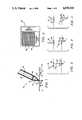
- FIG. 1is an enlarged cutaway simplified drawing of the tip portion of a pen type cursor for use with a digitizing tablet as wherein the present invention is applicable and illustrating the problem of pen tilt compensated for thereby.
- FIG. 2is a simplified cutaway drawing of a digitizing tablet as wherein the present invention is applicable and illustrating the spaced horizontal and vertical wires of the sensing grid thereof.
- FIGS. 3-5are simplified overlay drawings showing the change in the waveform at wires adjacent the gridwire closest to the zero crossing point as a result of pen tilt as employed in the compensation method of the present invention.
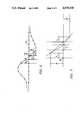
- FIG. 6is an enlarged drawing of the characteristic waveform resulting in an electromagnetic sensing digitizing tablet and pen system with the pen tilted and the parameters employed in the pen tilt compensation method of the present invention shown in detail.
- FIG. 7is a greatly enlarged drawing of the characteristic waveform resulting in an electromagnetic sensing digitizing tablet and pen system with the pen tilted illustrating an alternate approach to determining a pen tilt compensation factor according to the method of the present invention.
- the wires 28 of the tablet 24comprising the horizontal and vertical grid wires that are used to sense the location of the sensing coil 12 in the pen 10 are disposed in spaced relationship to one another and the actual "zero crossing" of the signal from one side of the actual location of the pen to the other side (the "data point") is calculated by an interpolation method. Between the actual wires of the grid (in each direction, i.e. X and Y) there is a change in voltage ( ⁇ V).
- the present inventionis based on the findings of extensive analysis of waveforms produced in a digitizing tablet system of the assignee hereof employing traditional prior art pen tilt techniques as mentioned above wherein the plus and minus peaks of the characteristic waveform (located several wires out from the data point) are employed. While it had long been assumed in the art that the peaks of the waveform were required to perform a meaningful correction for pen tilt, the applicants herein found that, in fact, the ⁇ Vs between the wire closest to the data point and the wires on each side thereof change in a consistent and useful manner which can be employed to compensate for pen tilt. This useful phenomenon is depicted in three cases (i.e. pen tilted left, pen vertical, and pen tilted right) in the drawings of FIGS. 2-4.
- the characteristic curve of the fieldis shown along with the voltages on the three wires (seen as circles in the drawings) near the data point. From a review of the drawing figures, it can be seen that the ⁇ Vs between the wires ( ⁇ P and ⁇ N for positive and negative, respectively) varies and that the difference between ⁇ P and ⁇ N exhibits a monotonic relationship to pen tilt.
- FIGS. 3-5represent the ideal case where the pen tip is located directly above one of the wires.
- the exceptional caseand, more typically, the data point or zero crossing point must be found by interpolation as mentioned earlier herein.
- the goal of the correction algorithm employed in the method of the present inventionis to determine the ⁇ P and ⁇ N voltages relative to the zero crossing point. This can best be explained and understood with respect to the drawing of FIG. 6 which depicts a tilted configuration. After the associated voltages for the data points as depicted and labeled in the drawing figure are obtained, the tilt correction is accomplished as follows:
- step 3 aboveAn alternate approach to step 3 above is depicted in FIG. 7.
- this approachone determines where a straight line passing through the ⁇ P and ⁇ N points on the straight line segments of interpolation passes through the zero voltage line. The difference between this point and the original "r" value is also roughly proportional to the tilt.
- the determination made by the method of the present inventionis a very close approximation; but is not intended to be an ultra-precision correction.
- What is offered by the present inventionis a correction for pen tilt which provides an acceptable level of tilt correction virtually all the way to the edge of the active area of the tablet.
- An important aspect as stated in the objectiveis that is does not require modification of the hardware of the tablet and its pen cursor. Over the prior art, it sacrifices a small degree of accuracy relative to pen tilt compensation for more useful correctable area on the tablet and direct use within the hardware in its present form.
Landscapes
- Engineering & Computer Science (AREA)
- Physics & Mathematics (AREA)
- General Engineering & Computer Science (AREA)
- Theoretical Computer Science (AREA)
- Electromagnetism (AREA)
- Human Computer Interaction (AREA)
- General Physics & Mathematics (AREA)
- Position Input By Displaying (AREA)
Abstract
Description
ΔP=(1-r)A+rB; and,
ΔN=(1-r)C+rD
Claims (2)
Priority Applications (1)
| Application Number | Priority Date | Filing Date | Title |
|---|---|---|---|
| US07/431,886US4939318A (en) | 1989-11-06 | 1989-11-06 | Digitizer pen tilt correction employing wires near the data point |
Applications Claiming Priority (1)
| Application Number | Priority Date | Filing Date | Title |
|---|---|---|---|
| US07/431,886US4939318A (en) | 1989-11-06 | 1989-11-06 | Digitizer pen tilt correction employing wires near the data point |
Publications (1)
| Publication Number | Publication Date |
|---|---|
| US4939318Atrue US4939318A (en) | 1990-07-03 |
Family
ID=23713856
Family Applications (1)
| Application Number | Title | Priority Date | Filing Date |
|---|---|---|---|
| US07/431,886Expired - Fee RelatedUS4939318A (en) | 1989-11-06 | 1989-11-06 | Digitizer pen tilt correction employing wires near the data point |
Country Status (1)
| Country | Link |
|---|---|
| US (1) | US4939318A (en) |
Cited By (15)
| Publication number | Priority date | Publication date | Assignee | Title |
|---|---|---|---|---|
| US5109225A (en)* | 1989-12-04 | 1992-04-28 | Seiko Instruments, Inc. | Coordinate reader with pointer inclination compensation |
| US5160813A (en)* | 1991-09-27 | 1992-11-03 | Calcomp Inc. | Cordless digitizer local conductor phase reference system |
| US5198623A (en)* | 1991-11-27 | 1993-03-30 | Calcomp, Inc. | Method for use in a digitizer for determining pen tilt |
| US5225637A (en)* | 1991-10-01 | 1993-07-06 | Kurta Corporation | Position resolving system |
| US5239489A (en)* | 1991-05-06 | 1993-08-24 | International Business Machines Corporation | Pen position and tilt estimators for a digitizer tablet |
| US5748110A (en)* | 1995-04-13 | 1998-05-05 | Wacom Co., Ltd. | Angular input information system relative to a tablet for determining an incline angle of a pointer or stylus |
| US5751229A (en)* | 1994-04-28 | 1998-05-12 | Wacom Co., Ltd. | Angular information input system |
| US6756970B2 (en) | 1998-11-20 | 2004-06-29 | Microsoft Corporation | Pen-based computer system |
| US20040160427A1 (en)* | 1998-11-20 | 2004-08-19 | Microsoft Corporation | Pen-based interface for a notepad computer |
| US20060022963A1 (en)* | 2004-07-30 | 2006-02-02 | Hewlett-Packard Development Company, L.P. | Calibrating digital pens |
| US7408838B1 (en) | 2007-01-22 | 2008-08-05 | Scale Master Technologies, Llc | Digitizing planimeter |
| US20130285990A1 (en)* | 2012-03-22 | 2013-10-31 | Samsung Electronics Co., Ltd. | Touch pen for direct information input |
| US20140009416A1 (en)* | 2012-07-03 | 2014-01-09 | Samsung Electronics Co., Ltd. | Coordinate compensation method and apparatus in digitizer, and electronic pen used in the same |
| US20140049270A1 (en)* | 2009-10-09 | 2014-02-20 | Egalax_Empia Technology Inc. | Method and device for analyzing positions |
| US9423911B2 (en) | 2014-02-12 | 2016-08-23 | E Ink Holdings Inc. | Correction method of touch point and electromagnetic-type touch panel using the same |
Citations (2)
| Publication number | Priority date | Publication date | Assignee | Title |
|---|---|---|---|---|
| US3873770A (en)* | 1974-03-21 | 1975-03-25 | Bendix Corp | Digital position measurement system with stylus tilt error compensation |
| US4568799A (en)* | 1983-09-30 | 1986-02-04 | Nec Corporation | Graphic input device |
- 1989
- 1989-11-06USUS07/431,886patent/US4939318A/ennot_activeExpired - Fee Related
Patent Citations (2)
| Publication number | Priority date | Publication date | Assignee | Title |
|---|---|---|---|---|
| US3873770A (en)* | 1974-03-21 | 1975-03-25 | Bendix Corp | Digital position measurement system with stylus tilt error compensation |
| US4568799A (en)* | 1983-09-30 | 1986-02-04 | Nec Corporation | Graphic input device |
Cited By (30)
| Publication number | Priority date | Publication date | Assignee | Title |
|---|---|---|---|---|
| US5109225A (en)* | 1989-12-04 | 1992-04-28 | Seiko Instruments, Inc. | Coordinate reader with pointer inclination compensation |
| US5239489A (en)* | 1991-05-06 | 1993-08-24 | International Business Machines Corporation | Pen position and tilt estimators for a digitizer tablet |
| US5160813A (en)* | 1991-09-27 | 1992-11-03 | Calcomp Inc. | Cordless digitizer local conductor phase reference system |
| US5225637A (en)* | 1991-10-01 | 1993-07-06 | Kurta Corporation | Position resolving system |
| US5198623A (en)* | 1991-11-27 | 1993-03-30 | Calcomp, Inc. | Method for use in a digitizer for determining pen tilt |
| US5751229A (en)* | 1994-04-28 | 1998-05-12 | Wacom Co., Ltd. | Angular information input system |
| US5748110A (en)* | 1995-04-13 | 1998-05-05 | Wacom Co., Ltd. | Angular input information system relative to a tablet for determining an incline angle of a pointer or stylus |
| US20060136840A1 (en)* | 1998-11-20 | 2006-06-22 | Microsoft Corporation | Pen-based interface for a notepad computer |
| US7703047B2 (en) | 1998-11-20 | 2010-04-20 | Microsoft Corporation | Pen-based interface for a notepad computer |
| US20050198593A1 (en)* | 1998-11-20 | 2005-09-08 | Microsoft Corporation | Pen-based interface for a notepad computer |
| US20050198592A1 (en)* | 1998-11-20 | 2005-09-08 | Microsoft Corporation | Pen-based interface for a notepad computer |
| US20050204301A1 (en)* | 1998-11-20 | 2005-09-15 | Microsoft Corporation | Pen-based interface for a notepad computer |
| US7825897B2 (en) | 1998-11-20 | 2010-11-02 | Microsoft Corporation | Pen-based interface for a notepad computer |
| US7032187B2 (en) | 1998-11-20 | 2006-04-18 | Microsoft Corporation | Pen-based interface for a notepad computer |
| US6756970B2 (en) | 1998-11-20 | 2004-06-29 | Microsoft Corporation | Pen-based computer system |
| US20040160427A1 (en)* | 1998-11-20 | 2004-08-19 | Microsoft Corporation | Pen-based interface for a notepad computer |
| US7559037B2 (en) | 1998-11-20 | 2009-07-07 | Microsoft Corporation | Pen-based interface for a notepad computer |
| US20060022963A1 (en)* | 2004-07-30 | 2006-02-02 | Hewlett-Packard Development Company, L.P. | Calibrating digital pens |
| US7656396B2 (en) | 2004-07-30 | 2010-02-02 | Hewlett-Packard Development Company, L.P. | Calibrating digital pens |
| US7408838B1 (en) | 2007-01-22 | 2008-08-05 | Scale Master Technologies, Llc | Digitizing planimeter |
| US20140049270A1 (en)* | 2009-10-09 | 2014-02-20 | Egalax_Empia Technology Inc. | Method and device for analyzing positions |
| US10101372B2 (en)* | 2009-10-09 | 2018-10-16 | Egalax_Empia Technology Inc. | Method and device for analyzing positions |
| US20130285990A1 (en)* | 2012-03-22 | 2013-10-31 | Samsung Electronics Co., Ltd. | Touch pen for direct information input |
| US9158392B2 (en)* | 2012-03-22 | 2015-10-13 | Samsung Electronics Co., Ltd | Touch pen with tilt correction |
| CN103529981A (en)* | 2012-07-03 | 2014-01-22 | 三星电子株式会社 | Coordinate compensation method and apparatus in digitizer, and electronic pen used in the same |
| KR20140004450A (en)* | 2012-07-03 | 2014-01-13 | 삼성전자주식회사 | Coordinate calibration method of digitizer, apparatus thereof, and electronic pen thereof |
| US9495022B2 (en)* | 2012-07-03 | 2016-11-15 | Samsung Electronics Co., Ltd. | Coordinate compensation method and apparatus in digitizer, and electronic pen used in the same |
| CN103529981B (en)* | 2012-07-03 | 2018-06-29 | 三星电子株式会社 | Coordinate compensation method and equipment in digital quantizer and its electronic pen used |
| US20140009416A1 (en)* | 2012-07-03 | 2014-01-09 | Samsung Electronics Co., Ltd. | Coordinate compensation method and apparatus in digitizer, and electronic pen used in the same |
| US9423911B2 (en) | 2014-02-12 | 2016-08-23 | E Ink Holdings Inc. | Correction method of touch point and electromagnetic-type touch panel using the same |
Similar Documents
| Publication | Publication Date | Title |
|---|---|---|
| US4939318A (en) | Digitizer pen tilt correction employing wires near the data point | |
| US5198623A (en) | Method for use in a digitizer for determining pen tilt | |
| US20020113779A1 (en) | Pressure sensitive writing tablet, control method and control program therefor | |
| EP0657842B1 (en) | Touch panel input device and method of generating input signals for an information processing device | |
| US8355009B2 (en) | Method and apparatus for determining coordinates of simultaneous touches on a touch sensor pad | |
| US7646380B2 (en) | Correction of alignment and linearity errors in a stylus input system | |
| US7477240B2 (en) | Input apparatus, computer apparatus, method for identifying input object, method for identifying input object in keyboard, and computer program | |
| US4650926A (en) | Electrographic system and method | |
| US4255617A (en) | Travelling wave digitizer | |
| JP2011065666A (en) | Apparatus for detecting object location | |
| US20020085003A1 (en) | Image processing method and an apparatus therefor | |
| EP0182144A2 (en) | Position indicating apparatus for use in a digitizing tablet system | |
| US20120062459A1 (en) | Device, method, and computer readable medium for mapping a graphics tablet to an associated display | |
| US5276282A (en) | Optimal scan sequence for RF magnetic digitizers | |
| GB2054300A (en) | Digitising the location of a coil | |
| CA1276258C (en) | Coordinate detecting method | |
| JPS63123165A (en) | Correlation of cursor and display entity | |
| CN106527955A (en) | Method and device for controlling slide of page | |
| US6404353B1 (en) | Method for optimizing the detection of the contact point of tactile capacitance surface | |
| US10108279B2 (en) | Device including electrode having thickness to facilitate tracking | |
| CN107357478B (en) | Electromagnetic touch inclination angle detection method, coordinate correction method and application thereof | |
| WO1994016408A1 (en) | Method and apparatus for editing electronic ink | |
| JPS63123166A (en) | Correlation of cursor and entity | |
| HUT75820A (en) | Method of stroke segmentation for handwritten input | |
| US5025410A (en) | Coordinate reading apparatus |
Legal Events
| Date | Code | Title | Description |
|---|---|---|---|
| AS | Assignment | Owner name:CALCOMP INC., CALIFORNIA Free format text:ASSIGNMENT OF ASSIGNORS INTEREST.;ASSIGNORS:WATSON, JAMES S.;DOUBRAVA, DANA;REEL/FRAME:005171/0963 Effective date:19891030 | |
| FPAY | Fee payment | Year of fee payment:4 | |
| FEPP | Fee payment procedure | Free format text:PAYOR NUMBER ASSIGNED (ORIGINAL EVENT CODE: ASPN); ENTITY STATUS OF PATENT OWNER: LARGE ENTITY | |
| FPAY | Fee payment | Year of fee payment:8 | |
| AS | Assignment | Owner name:MCG FINANCE CORPORATION, VIRGINIA Free format text:SECURITY AGREEMENT;ASSIGNOR:GTCO CORPORATION;REEL/FRAME:010070/0137 Effective date:19990201 | |
| AS | Assignment | Owner name:FIRST UNION NATIONAL BANK, A CORPORATION OF NORTH Free format text:SECURITY INTEREST;ASSIGNOR:GTCO CORPORATION;REEL/FRAME:010514/0611 Effective date:19991227 | |
| AS | Assignment | Owner name:FIRST UNION NATIONAL BANK, VIRGINIA Free format text:SECURITY INTEREST;ASSIGNOR:GTCO CORPORATION;REEL/FRAME:010547/0449 Effective date:20000225 | |
| AS | Assignment | Owner name:GTCO CORPORATION, MARYLAND Free format text:RELEASE OF SECURITY INTEREST;ASSIGNOR:MCG FINANCE CORPORATION;REEL/FRAME:010696/0359 Effective date:20000112 | |
| REMI | Maintenance fee reminder mailed | ||
| LAPS | Lapse for failure to pay maintenance fees | ||
| STCH | Information on status: patent discontinuation | Free format text:PATENT EXPIRED DUE TO NONPAYMENT OF MAINTENANCE FEES UNDER 37 CFR 1.362 | |
| FP | Lapsed due to failure to pay maintenance fee | Effective date:20020703 | |
| AS | Assignment | Owner name:GTCO CORPORATION, TEXAS Free format text:RELEASE BY SECURED PARTY;ASSIGNOR:WACHOVIA BANK, NATIONAL ASSOCIATION, FKA FIRST UNION NATIONAL BANK;REEL/FRAME:020299/0585 Effective date:20071228 |