US4938207A - Knee brace having plurality of fluid filled chambers surrounding knee - Google Patents
Knee brace having plurality of fluid filled chambers surrounding kneeDownload PDFInfo
- Publication number
- US4938207A US4938207AUS06/920,411US92041186AUS4938207AUS 4938207 AUS4938207 AUS 4938207AUS 92041186 AUS92041186 AUS 92041186AUS 4938207 AUS4938207 AUS 4938207A
- Authority
- US
- United States
- Prior art keywords
- knee
- sheath
- chamber
- chambers
- fluid
- Prior art date
- Legal status (The legal status is an assumption and is not a legal conclusion. Google has not performed a legal analysis and makes no representation as to the accuracy of the status listed.)
- Expired - Fee Related
Links
- 210000003127kneeAnatomy0.000titleclaimsabstractdescription102
- 239000012530fluidSubstances0.000titleclaimsabstractdescription58
- 239000000835fiberSubstances0.000claimsdescription26
- 210000004417patellaAnatomy0.000claimsdescription21
- 210000002414legAnatomy0.000claimsdescription13
- 210000000689upper legAnatomy0.000claimsdescription12
- 244000309466calfSpecies0.000claimsdescription11
- 230000002706hydrostatic effectEffects0.000claimsdescription11
- 230000002159abnormal effectEffects0.000claimsdescription5
- 238000005452bendingMethods0.000claims2
- 210000000629knee jointAnatomy0.000abstractdescription11
- 208000027418Wounds and injuryDiseases0.000description6
- 230000006378damageEffects0.000description6
- 208000014674injuryDiseases0.000description6
- 239000000463materialSubstances0.000description5
- 230000000386athletic effectEffects0.000description4
- 230000008901benefitEffects0.000description3
- 230000001225therapeutic effectEffects0.000description3
- 239000003570airSubstances0.000description2
- 230000000694effectsEffects0.000description2
- 239000004744fabricSubstances0.000description2
- 230000035876healingEffects0.000description2
- 230000004048modificationEffects0.000description2
- 238000012986modificationMethods0.000description2
- 230000008707rearrangementEffects0.000description2
- 238000006467substitution reactionMethods0.000description2
- 210000002435tendonAnatomy0.000description2
- XLYOFNOQVPJJNP-UHFFFAOYSA-NwaterSubstancesOXLYOFNOQVPJJNP-UHFFFAOYSA-N0.000description2
- 108010010803GelatinProteins0.000description1
- 229920000914Metallic fiberPolymers0.000description1
- 230000009471actionEffects0.000description1
- 230000009286beneficial effectEffects0.000description1
- 210000000988bone and boneAnatomy0.000description1
- 210000000845cartilageAnatomy0.000description1
- 230000003247decreasing effectEffects0.000description1
- 239000000499gelSubstances0.000description1
- 239000008273gelatinSubstances0.000description1
- 229920000159gelatinPolymers0.000description1
- 235000019322gelatineNutrition0.000description1
- 235000011852gelatine dessertsNutrition0.000description1
- 210000003041ligamentAnatomy0.000description1
- 230000005012migrationEffects0.000description1
- 238000013508migrationMethods0.000description1
- 229920001084poly(chloroprene)Polymers0.000description1
- 230000010349pulsationEffects0.000description1
- 238000000926separation methodMethods0.000description1
- 238000009958sewingMethods0.000description1
Images


Classifications
- A—HUMAN NECESSITIES
- A61—MEDICAL OR VETERINARY SCIENCE; HYGIENE
- A61F—FILTERS IMPLANTABLE INTO BLOOD VESSELS; PROSTHESES; DEVICES PROVIDING PATENCY TO, OR PREVENTING COLLAPSING OF, TUBULAR STRUCTURES OF THE BODY, e.g. STENTS; ORTHOPAEDIC, NURSING OR CONTRACEPTIVE DEVICES; FOMENTATION; TREATMENT OR PROTECTION OF EYES OR EARS; BANDAGES, DRESSINGS OR ABSORBENT PADS; FIRST-AID KITS
- A61F5/00—Orthopaedic methods or devices for non-surgical treatment of bones or joints; Nursing devices ; Anti-rape devices
- A61F5/01—Orthopaedic devices, e.g. long-term immobilising or pressure directing devices for treating broken or deformed bones such as splints, casts or braces
- A61F5/0102—Orthopaedic devices, e.g. long-term immobilising or pressure directing devices for treating broken or deformed bones such as splints, casts or braces specially adapted for correcting deformities of the limbs or for supporting them; Ortheses, e.g. with articulations
- A61F5/0104—Orthopaedic devices, e.g. long-term immobilising or pressure directing devices for treating broken or deformed bones such as splints, casts or braces specially adapted for correcting deformities of the limbs or for supporting them; Ortheses, e.g. with articulations without articulation
- A61F5/0106—Orthopaedic devices, e.g. long-term immobilising or pressure directing devices for treating broken or deformed bones such as splints, casts or braces specially adapted for correcting deformities of the limbs or for supporting them; Ortheses, e.g. with articulations without articulation for the knees
- A61F5/0109—Sleeve-like structures
- A—HUMAN NECESSITIES
- A61—MEDICAL OR VETERINARY SCIENCE; HYGIENE
- A61F—FILTERS IMPLANTABLE INTO BLOOD VESSELS; PROSTHESES; DEVICES PROVIDING PATENCY TO, OR PREVENTING COLLAPSING OF, TUBULAR STRUCTURES OF THE BODY, e.g. STENTS; ORTHOPAEDIC, NURSING OR CONTRACEPTIVE DEVICES; FOMENTATION; TREATMENT OR PROTECTION OF EYES OR EARS; BANDAGES, DRESSINGS OR ABSORBENT PADS; FIRST-AID KITS
- A61F5/00—Orthopaedic methods or devices for non-surgical treatment of bones or joints; Nursing devices ; Anti-rape devices
- A61F5/01—Orthopaedic devices, e.g. long-term immobilising or pressure directing devices for treating broken or deformed bones such as splints, casts or braces
- A61F5/0102—Orthopaedic devices, e.g. long-term immobilising or pressure directing devices for treating broken or deformed bones such as splints, casts or braces specially adapted for correcting deformities of the limbs or for supporting them; Ortheses, e.g. with articulations
- A61F2005/0132—Additional features of the articulation
- A61F2005/0172—Additional features of the articulation with cushions
- A61F2005/0176—Additional features of the articulation with cushions supporting the patella
- Y—GENERAL TAGGING OF NEW TECHNOLOGICAL DEVELOPMENTS; GENERAL TAGGING OF CROSS-SECTIONAL TECHNOLOGIES SPANNING OVER SEVERAL SECTIONS OF THE IPC; TECHNICAL SUBJECTS COVERED BY FORMER USPC CROSS-REFERENCE ART COLLECTIONS [XRACs] AND DIGESTS
- Y10—TECHNICAL SUBJECTS COVERED BY FORMER USPC
- Y10S—TECHNICAL SUBJECTS COVERED BY FORMER USPC CROSS-REFERENCE ART COLLECTIONS [XRACs] AND DIGESTS
- Y10S128/00—Surgery
- Y10S128/20—Inflatable splint
Definitions
- the present inventionrelates to a knee brace having a plurality of interconnected fluid filled compartments positioned to provide variable support to the knee joint as the knee is bent.
- U.S. Pat. No. 3,965,486, to Lightbodydiscloses a pneumatic knee pad having two chambers and a multiplicity of hollow fingers communicating with the chambers. When the knee is bent, the air in one or both of the chambers is forced into one or more of the fingers which tighten against the knee prohibiting separation of the various bones of the knee and reducing the risk of torn ligaments, tendons, and cartilage.
- the prior artalso discloses a pair of fluid filled chambers positioned on the thigh and calf adjacent the knee joint and fluidly connected so as to permit fluid migration from one side of the device to the other upon application of an external force to the knee.
- These devicesare principally used to protect the user's knee from injuries during athletic contests while permitting free use of the leg.
- an external forcesuch as contact during an athletic competition
- a lateral force to the kneecauses fluid to migrate from the engaged side of the knee to the opposite side causing expansion of the fluid filled chamber on the opposite side.
- the present inventionprovides a knee brace having a plurality of fluid filled chambers located on the thigh and calf proximate the knee cap and fluidly connected to a plurality of side chambers mounted behind the knee cap on the side of the knee.
- flexing the kneecauses an increase in pressure in the side chambers, giving lateral support to the knee, holding a weak joint together and protecting a damaged area from further injury.
- the kneewill experience beneficial therapeutic effect from the pulsation of pressure in the side chambers.
- the knee braceprovides fluid chambers formed with an outer surface of an inelastic material which prohibits dissipation of hydrostatic pressure through the expansion of the outer surface, thereby concentrating the pressure on the user's knee.
- the knee braceincludes a plurality of fluid filled chambers located on the thigh and calf proximate the knee cap which may be either filled with or drained of fluid so as to provide application of different hydrostatic pressures to different points on the user's knee, and also to provide a means for varying the amount of hydrostatic pressure obtained when the knee is bent.
- This aspect of the present inventionis useful in that the hydrostatic pressure may be relieved as the knee heals, or increased if the knee is re-injured to achieve the maximum therapeutic effect of the device.
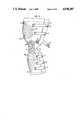
- FIG. 1is a perspective view of the apparatus of the present invention shown applied to a user's leg;
- FIG. 2is a front view of the apparatus of the present invention
- FIG. 3is a side view of the apparatus of the present invention.
- FIG. 4is a top view of the apparatus of the present invention shown in a flat position
- FIG. 5is a sectional view of the apparatus of the present invention taken along lines 5--5 in FIG. 2;
- FIG. 6ais a perspective schematic view of the fluid compartments of the apparatus of the present invention.
- FIG. 6bis a perspective schematic view of the fluid compartments of the apparatus of the present invention.
- FIG. 7is a perspective view of an alternative embodiment of the apparatus of the present invention.
- the apparatus of the present inventioncomprises a flexible sheath 20 which is mounted on a human thigh 10 and calf 12 so as to frictionally engage the leg at the knee area.
- Sheath 20is made of a flexible material such as cloth or neoprene, but is of sufficient strenght to allow it to be securely mounted about the leg while simultaneously allowing the leg to bend at the knee.
- Sheath 20has an ovular cutout 30 defined by edge 32, and is located so as to receive the patella, commonly known as the knee cap, allowing the patella to protrude from sheath 20 to permit greater flexibility of the knee. Further, cutout 30 is sized so as to retain and locate the patella to eliminate the risk of improper movement of the patella due to broken or injured tendons.
- the apparatus of the present inventionis secured about the user's leg above the knee by adjustable straps 22 and below the knee by adjustable straps 24.
- straps 22 and 24can employ VELCRO (hook and loop) fastening surfaces to allow precise adjustment of the fit of sheath 20, and that in alternative embodiments, buttons, snaps, hooks or zippers, for example, may be employed if suitable.
- straps 22have VELCRO fastening surfaces 84 located so as to engage with cooperating VELCRO attachment surfaces 86 located on sheath 20 to provide a secure fit of the sheath above the user's thigh.
- 1, 2 and 3show three straps above the knee and three straps below the knee, more or fewer straps may be employed as deemed suitable. For example, if the apparatus of the present invention is to be worn during athletic competition more staps may be employed to assure that the apparatus does not slip during use.
- sheath 20is shown in a flat position.
- Proximate to ovular cutout 30are fluid chambers 50 and 52, which during use are located above the knee cap, and fluid chambers 56 and 60, which during use are located below the knee cap. Fluidly connected to each of these chambers is a corresponding side chamber, which during use are located to the side and behind the knee cap.
- fluid chamber 50is fluidly connected to side chamber 64
- chamber 52is connected to side chamber 54
- chamber 56is connected to side chamber 58
- chamber 60is connected to side chamber 62.
- sheath 20has cutouts 40 and 42.
- Proximate cutout 42are flaps 80 and 82 on which straps 22 and 24 are located. Cutouts 40 and 42 are located so that when sheath 20 is mounted on the leg, the cutouts are located directly behind the knee cap to allow the user to bend his knee freely without binding or other interference from the sheath.
- inelastic fibersare employed in the exterior boundary of the fluid chambers.
- chamber 50has lateral fibers 102 overlaid with vertical fibers 130 to comprise its external surface.
- fluid chamber 52has lateral fibers 100 overlaid with vertical fibers 132 to comprise its external surface.
- Similar fiber configurationsare used for chamber 60 where lateral fibers 104 and vertical fibers 134 comprise its exterior surface, and for chamber 56 where lateral fibers 106 and vertical fibers 136 are employed.
- Vertical fibers 130 and 132are connected to vertical fibers 134 and 136, respectively, by fibers 88 and 90, which fibers lie proximate to ovular cutout 30.
- fibers 88 and 90also serve to retain and locate the user's knee cap during use.
- fibers 130, 132, 134, 136, 88, 90, 100, 102, 104, and 106comprise metallic fibers interwoven with the material that comprises the outer surface of the various fluid chambers. This can be accomplished by sewing the appropriate layer or layers with wire thread.
- side chambers 54 and 58have an exterior surface comprising a tightly interwoven fiber structure.
- the tight weave of inelastic fibers 122assures that little or no external deformation of chambers 54 and 58 occur, and that all expansion due to increasing pressure in these chambers is directed and focused towards the interior surfaces of these chambers proximate to the user's knee.
- inelastic fibers 120comprise a tightly interwoven fiber structure covering side chambers 62 and 64, assuring that all increases in pressure in these chambers is directed and focused towards the surface proximate to the user's knee.
- chambers 50, 52, 54, 56, 58, 60, 62 and 64can be filled with air, water, gelatin, or other fluids which can easily compress between the chambers above and below cutout 30 and the various side chambers.
- valves 200, 202, 204, and 206allow fluid or air to be injected into or removed from chambers 50, 52, 60, and 56, respectively.
- sheath 20has located on its interior surface facing 300.
- Facing 300is of a suitable material, such as cloth, so as to readily frictionally engage the user's thigh and calf to comfortably secure the apparatus of the present invention about the user's knee.
- Chambers 56 and 60have inner liners 302 and 304, respectively, and outer liners 306 and 308, respectively. These liners serve to retain the fluids contained in each of these chambers, and it will be understood that all of the fluid chambers of the present invention have similar liners.
- Inelastic fibers 134 and 136are shown as interwoven with the material of sheath 20.
- the boundaries of each fluid chamberis reinforced with a strong inelastic stitching, such as wire stitching.
- the boundaries of fluid chambers 56are reinforced with wire stitching 320 and 322, and the boundaries of fluid chambers 60 are reinforced with wire stitching 324 and 326.
- the apparatus of the present inventionmay be used in combination with the standard knee brace as used in the prior art.
- the apparatus of the present inventionmay be used in conjunction with two pair of flattened vertical support shafts journaled by a rivet, which pair of shafts prohibit abnormal lateral, fore and aft motion of the knee.
- the apparatus of the present inventionis used in conjunction with vertical shafts 400 and 420 that are connected by journal 330 at a point corresponding to the point at which the human knee flexes.
- Vertical shafts 400 and 420are attached to support straps 350 and 360, respectively.
- Support strap 350frictionally engages about the user's thigh and support strap 360 frictionally engages about the user's calf, and serve to support a corresponding pair of vertical shafts (not shown) on the side of the knee opposite to shafts 400 and 420.
- shafts 400 and 420prohibit normal lateral, fore and aft motion of the user's knee and may be used in conjunction with the apparatus of the present invention to promote healing of prior existing injuries to the knee and to prohibit future injuries of the knee which may be occasioned during athletic competition.
- the userplaces sheath 20 with its self-contained fluid chambers about his thigh and calf so that the knee cap protrudes through cutout 30.
- Adjustable straps 22 and 24are fastened so that sheath 20 is comfortably engaged with the user's thigh and calf to permit walking and/or running activities.
- the fluid pressure in each of the fluid chambersis at a minimum and is evenly distributed on the interior surface of sheath 20 at points both above and below the knee cap and to each side of the knee cap.
- the volumes of fluid chambers 50, 52, 56, and 60are decreased.
- the inelastic fibers which span the outer surfaces of these fluid chambersare pulled tight so as to decrease their respective volumes. Consequently, the fluid pressure in each chamber increases, and the increase in pressure is distributed to the various side chambers. This increase in pressure in the side chambers is directed to the sides of the user's knee because of the inelastic outer covering 120 and 122 of these side chambers.
- each fluid compartmentmay be filled with a moderate amount of air, water, gel or other fluid so as to result in only a moderate force upon the side of the knee during operation.
- various fluid chambersmay be filled or drained so as to either increase or decrease the resulting pressure at a desired location on the side of the knee. For example, if fluid chamber 52 is filled through valve 202 so as to have an excess amount of fluid therein, side chamber 54 would exert a correspondingly higher pressure to the side of the user's knee than would the other side chambers 58, 62, and 64.
- fluid chamber 52can be drained through valve 202 so that the corresponding pressure exerted on the user's knee by side chamber 54 would be less than the pressures exerted by the other side chambers.
- the present inventionprovides a knee brace which provides lateral support to the knee and where such support may be adjusted in accordance with the amount of fluid loaded in the respective chambers provided by the brace. Further, upon flexing of the knee, the brace provides added pressure at the sides of the knee joint thus providing additional lateral support.
- the knee bracecan be tailored to the specific needs of the user. Further, because four separate chambers are provided, different fluids may be selected and used in the various chambers, thus further adding to the versatility of the brace. Additionally, because of the varying pressures which result as the knee is flexed while using the present knee brace, a massaging action is provided, where desired.
- heated or cooled fluidsmay be used to provide the therapeutic benefit which will be occasioned by the use of such fluids at the desired locations adjacent the knee joint.
- all of these benefitsare provided with a brace which is both easy to apply and which provides a minimum of restriction with respect to movement of the knee. Further, when the leg is at the extended, normally at rest position, the pressures applied by the brace are at a minimum.
Landscapes
- Health & Medical Sciences (AREA)
- Nursing (AREA)
- Orthopedic Medicine & Surgery (AREA)
- Engineering & Computer Science (AREA)
- Biomedical Technology (AREA)
- Heart & Thoracic Surgery (AREA)
- Vascular Medicine (AREA)
- Life Sciences & Earth Sciences (AREA)
- Animal Behavior & Ethology (AREA)
- General Health & Medical Sciences (AREA)
- Public Health (AREA)
- Veterinary Medicine (AREA)
- Orthopedics, Nursing, And Contraception (AREA)
Abstract
Description
The present invention relates to a knee brace having a plurality of interconnected fluid filled compartments positioned to provide variable support to the knee joint as the knee is bent.
It is well known in the prior art to use an apparatus which frictionally engages a human thigh and calf to prohibit abnormal lateral, fore and aft motion of these body members, avoiding improper stresses on the knee. In particular, U.S. Pat. No. 2,144,641, to Snyder, provides a knee brace which frictionally engages both the thigh and calf and has a pair of flattened vertical support shafts journaled by a rivet, where the shafts prohibit abnormal lateral, fore and aft motion of the knee. These devices are useful where the user's knee has been previously injured, protecting the knee from further injury and permitting continued activity while the knee joint is healing.
The prior art also contemplates the use of knee pads to both protect the knee and give support to it, giving greater support when the knee is bent. In particular, U.S. Pat. No. 3,965,486, to Lightbody, discloses a pneumatic knee pad having two chambers and a multiplicity of hollow fingers communicating with the chambers. When the knee is bent, the air in one or both of the chambers is forced into one or more of the fingers which tighten against the knee prohibiting separation of the various bones of the knee and reducing the risk of torn ligaments, tendons, and cartilage.
The prior art also discloses a pair of fluid filled chambers positioned on the thigh and calf adjacent the knee joint and fluidly connected so as to permit fluid migration from one side of the device to the other upon application of an external force to the knee. These devices are principally used to protect the user's knee from injuries during athletic contests while permitting free use of the leg. Upon the application of an external force, such as contact during an athletic competition, a lateral force to the knee causes fluid to migrate from the engaged side of the knee to the opposite side causing expansion of the fluid filled chamber on the opposite side. By increasing fluid pressure on the side opposite that of impact, the knee is better braced, thereby reducing the possibility of injury to the knee joint.
Although these prior art devices provide some support to the knee joint, they have failed to provide control support in conjunction with and as a result of flexure of the knee. Further, the devices have failed to provide adequate support to the knee joint without resulting in overly restricting movement of the knee. Thus, a need exists for a knee brace which provides controlled lateral support at defined points of knee flexure without restricting movement of the knee joint.
The present invention provides a knee brace having a plurality of fluid filled chambers located on the thigh and calf proximate the knee cap and fluidly connected to a plurality of side chambers mounted behind the knee cap on the side of the knee. In use, flexing the knee causes an increase in pressure in the side chambers, giving lateral support to the knee, holding a weak joint together and protecting a damaged area from further injury. Further, during walking or running, the knee will experience beneficial therapeutic effect from the pulsation of pressure in the side chambers.
In another aspect of the invention, the knee brace provides fluid chambers formed with an outer surface of an inelastic material which prohibits dissipation of hydrostatic pressure through the expansion of the outer surface, thereby concentrating the pressure on the user's knee.
According to a further aspect of the invention, the knee brace includes a plurality of fluid filled chambers located on the thigh and calf proximate the knee cap which may be either filled with or drained of fluid so as to provide application of different hydrostatic pressures to different points on the user's knee, and also to provide a means for varying the amount of hydrostatic pressure obtained when the knee is bent. This aspect of the present invention is useful in that the hydrostatic pressure may be relieved as the knee heals, or increased if the knee is re-injured to achieve the maximum therapeutic effect of the device.
A more complete understanding of the invention and its advantages will be apparent from the following Detailed Description, taken in conjunction with the accompanying drawings in which:
FIG. 1 is a perspective view of the apparatus of the present invention shown applied to a user's leg;
FIG. 2 is a front view of the apparatus of the present invention;
FIG. 3 is a side view of the apparatus of the present invention;
FIG. 4 is a top view of the apparatus of the present invention shown in a flat position;
FIG. 5 is a sectional view of the apparatus of the present invention taken alonglines 5--5 in FIG. 2;
FIG. 6a is a perspective schematic view of the fluid compartments of the apparatus of the present invention;
FIG. 6b is a perspective schematic view of the fluid compartments of the apparatus of the present invention; and
FIG. 7 is a perspective view of an alternative embodiment of the apparatus of the present invention.
Referring initially to FIGS. 1, 2 and 3, the apparatus of the present invention comprises aflexible sheath 20 which is mounted on ahuman thigh 10 andcalf 12 so as to frictionally engage the leg at the knee area. Sheath 20 is made of a flexible material such as cloth or neoprene, but is of sufficient strenght to allow it to be securely mounted about the leg while simultaneously allowing the leg to bend at the knee.Sheath 20 has anovular cutout 30 defined byedge 32, and is located so as to receive the patella, commonly known as the knee cap, allowing the patella to protrude fromsheath 20 to permit greater flexibility of the knee. Further,cutout 30 is sized so as to retain and locate the patella to eliminate the risk of improper movement of the patella due to broken or injured tendons.
The apparatus of the present invention is secured about the user's leg above the knee byadjustable straps 22 and below the knee byadjustable straps 24. It will be understood thatstraps sheath 20, and that in alternative embodiments, buttons, snaps, hooks or zippers, for example, may be employed if suitable. As shown in FIG. 3,straps 22 have VELCROfastening surfaces 84 located so as to engage with cooperating VELCROattachment surfaces 86 located onsheath 20 to provide a secure fit of the sheath above the user's thigh. Further, while FIGS. 1, 2 and 3 show three straps above the knee and three straps below the knee, more or fewer straps may be employed as deemed suitable. For example, if the apparatus of the present invention is to be worn during athletic competition more staps may be employed to assure that the apparatus does not slip during use.
Referring now to FIG. 4,sheath 20 is shown in a flat position. Proximate to ovularcutout 30 arefluid chambers fluid chambers fluid chamber 50 is fluidly connected toside chamber 64,chamber 52 is connected toside chamber 54,chamber 56 is connected toside chamber 58 andchamber 60 is connected to side chamber 62.
As shown in FIG. 4,sheath 20 hascutouts Proximate cutout 42 areflaps straps Cutouts sheath 20 is mounted on the leg, the cutouts are located directly behind the knee cap to allow the user to bend his knee freely without binding or other interference from the sheath.
As shown in FIGS. 2 and 3, inelastic fibers are employed in the exterior boundary of the fluid chambers. In particular,chamber 50 has lateral fibers 102 overlaid with vertical fibers 130 to comprise its external surface. Likewise,fluid chamber 52 haslateral fibers 100 overlaid withvertical fibers 132 to comprise its external surface. Similar fiber configurations are used forchamber 60 where lateral fibers 104 andvertical fibers 134 comprise its exterior surface, and forchamber 56 wherelateral fibers 106 andvertical fibers 136 are employed.Vertical fibers 130 and 132 are connected tovertical fibers fibers 88 and 90, which fibers lie proximate to ovularcutout 30. In addition to connecting the vertical fibers above and belowcutout 30,fibers 88 and 90 also serve to retain and locate the user's knee cap during use.
In the preferred embodiment,fibers side chambers chambers side chambers 62 and 64, assuring that all increases in pressure in these chambers is directed and focused towards the surface proximate to the user's knee.
It will be understood thatchambers cutout 30 and the various side chambers. As shown in FIG. 2,valves chambers
Referring now to FIG. 5,sheath 20 has located on its interior surface facing 300. Facing 300 is of a suitable material, such as cloth, so as to readily frictionally engage the user's thigh and calf to comfortably secure the apparatus of the present invention about the user's knee.Chambers inner liners outer liners Inelastic fibers sheath 20. The boundaries of each fluid chamber is reinforced with a strong inelastic stitching, such as wire stitching. In particular, as shown in FIG. 5 the boundaries offluid chambers 56 are reinforced withwire stitching fluid chambers 60 are reinforced withwire stitching
As shown in FIG. 7, the apparatus of the present invention may be used in combination with the standard knee brace as used in the prior art. In particular, the apparatus of the present invention may be used in conjunction with two pair of flattened vertical support shafts journaled by a rivet, which pair of shafts prohibit abnormal lateral, fore and aft motion of the knee. As is seen in FIG. 7, the apparatus of the present invention is used in conjunction withvertical shafts journal 330 at a point corresponding to the point at which the human knee flexes.Vertical shafts straps Support strap 350 frictionally engages about the user's thigh andsupport strap 360 frictionally engages about the user's calf, and serve to support a corresponding pair of vertical shafts (not shown) on the side of the knee opposite toshafts shafts
In operation, the user placessheath 20 with its self-contained fluid chambers about his thigh and calf so that the knee cap protrudes throughcutout 30.Adjustable straps sheath 20 is comfortably engaged with the user's thigh and calf to permit walking and/or running activities. When the user's leg is in a straight position (as shown in FIG. 6a) the fluid pressure in each of the fluid chambers is at a minimum and is evenly distributed on the interior surface ofsheath 20 at points both above and below the knee cap and to each side of the knee cap. During use, when the user bends the knee, the volumes offluid chambers
Prior to the mounting ofsheath 20 on the user's leg, the user may insert or remove fluid from the various fluid chambers throughvalves fluid chamber 52 is filled throughvalve 202 so as to have an excess amount of fluid therein,side chamber 54 would exert a correspondingly higher pressure to the side of the user's knee than would theother side chambers fluid chamber 52 can be drained throughvalve 202 so that the corresponding pressure exerted on the user's knee byside chamber 54 would be less than the pressures exerted by the other side chambers.
Thus, the present invention provides a knee brace which provides lateral support to the knee and where such support may be adjusted in accordance with the amount of fluid loaded in the respective chambers provided by the brace. Further, upon flexing of the knee, the brace provides added pressure at the sides of the knee joint thus providing additional lateral support. By adjusting the fluid pressure in the four separate chambers, the knee brace can be tailored to the specific needs of the user. Further, because four separate chambers are provided, different fluids may be selected and used in the various chambers, thus further adding to the versatility of the brace. Additionally, because of the varying pressures which result as the knee is flexed while using the present knee brace, a massaging action is provided, where desired. Additionally, heated or cooled fluids may be used to provide the therapeutic benefit which will be occasioned by the use of such fluids at the desired locations adjacent the knee joint. Further, all of these benefits are provided with a brace which is both easy to apply and which provides a minimum of restriction with respect to movement of the knee. Further, when the leg is at the extended, normally at rest position, the pressures applied by the brace are at a minimum.
Although preferred embodiments of the invention have been described in the foregoing detailed description and illustrated in the accompanying drawings, it will be understood that the invention is not limited to the embodiments disclosed, but is capable of numerous rearrangements, modifications, and substitution of parts and elements without departing from the spirit of the invention. The present invention is therefore intended to encompass such rearrangements, modifications, and substitution of parts and elements as fall within the scope of the invention.
Claims (8)
1. A knee brace comprising:
a flexible sheath member sized so as to extend about the human thigh and calf to embrace the knee area of the leg, having a cutout portion to receive and locate the knee cap, means to exert a hydrostatic pressure on said knee area when said knee is bent comprising first and second fluid filled chambers located so as to be proximate to the above said knee cap, each fluidly connected to a corresponding first and second side chamber, wherein said first side chamber is located on one side of the knee and said second side chamber is located on the opposite side of the knee; and a third and fourth fluid filled chamber located so as to be proximate to and below said knee cap, each fluidly connected to a corresponding third and fourth side chamber, wherein said third side chamber is located on one side of the knee and said fourth side chamber is located on the opposite side of the knee where the hydrostatic pressure in said first, second, third and fourth side chambers is increased by a corresponding increase in the hydrostatic pressure in the first, second, third and fourth fluid filled chambers occasioned upon the bending of the knee; said first, second, third and fourth chambers having no fluid interconnection with each other.
2. The knee brace of claim 1, further comprising an attachment means comprising releasable fastening straps which are adjustably secured about said sheath so as to allow said sheath to be frictionally engaged about the knee area of the human leg.
3. The knee brace of claim 1, wherein said cutout portion is sized to allow the knee cap to protrude from said sheath, and said sheath further comprises first and second notches located so that when said sheath is attached to a human leg said first and second notches are located to form a gap in said sheath behind said knee to allow free bending movement thereof.
4. The knee brace of claim 1, wherein said first, second, third and fourth fluid filled chambers have internal and external surfaces, said internal surface being proximate the knee, and located on each chamber's external surface is at least a single ply of an inelastic fiber positioned so as to substantially prohibit the expansion of each said fluid filled chamber's external surface upon the increase in hydrostatic pressure in each chamber.
5. The knee brace of claim 4, wherein said first, second, third and fourth side chambers have internal and external surfaces, and the external surface of each side chamber comprises an interwoven inelastic fiber structure positioned so as to prohibit the expansion of the side chamber's exterior surfaces upon increase of hydrostatic pressure therein, thereby directing any increase in hydrostatic pressure to each said chamber's interior surface proximate the knee area.
6. The knee brace of claim 1, further comprising a plurality of inelastic fibers located proximate to said cutout area so as to locate and retain said knee cap when said knee is bent.
7. The knee brace of claim 1, further comprising:
first and second shafts, wherein said first shaft has first and second ends, said first end being attached to said sheath at a point above the knee and said second end being attached to said sheath at a point below the knee, said first shaft comprising first and second members journaled by a rivet at a point corresponding to the point at which the human knee flexes so as to prohibit abnormal lateral, fore, and aft motion of the knee while allowing normal flexing thereof; and
said second shaft has first and second ends, said first end being attached to said sheath at a point above the knee and said second end being attached to said sheath at a point below the knee, said second shaft comprising first and second members journaled by a rivet at a point corresponding to the point at which the human knee flexes so as to prohibit abnormal lateral, fore and aft motion of the knee while allowing normal flexing thereof.
8. The knee brace of claim 1, further comprising means to add or remove fluid from said first fluid filled chamber, and a means to add or remove fluid from said second fluid filled chamber, wherein said fluid filling means permits the hydrostatic pressure exerted by said first and second fluid filled chambers on said knee area to be either increased or reduced a predetermined amount.
Priority Applications (1)
| Application Number | Priority Date | Filing Date | Title |
|---|---|---|---|
| US06/920,411US4938207A (en) | 1986-10-20 | 1986-10-20 | Knee brace having plurality of fluid filled chambers surrounding knee |
Applications Claiming Priority (1)
| Application Number | Priority Date | Filing Date | Title |
|---|---|---|---|
| US06/920,411US4938207A (en) | 1986-10-20 | 1986-10-20 | Knee brace having plurality of fluid filled chambers surrounding knee |
Publications (1)
| Publication Number | Publication Date |
|---|---|
| US4938207Atrue US4938207A (en) | 1990-07-03 |
Family
ID=25443704
Family Applications (1)
| Application Number | Title | Priority Date | Filing Date |
|---|---|---|---|
| US06/920,411Expired - Fee RelatedUS4938207A (en) | 1986-10-20 | 1986-10-20 | Knee brace having plurality of fluid filled chambers surrounding knee |
Country Status (1)
| Country | Link |
|---|---|
| US (1) | US4938207A (en) |
Cited By (106)
| Publication number | Priority date | Publication date | Assignee | Title |
|---|---|---|---|---|
| US5086761A (en)* | 1990-03-26 | 1992-02-11 | Ingram Patrick T | Multi-adjustable knee brace |
| USD329497S (en) | 1990-06-29 | 1992-09-15 | Daniel Pryor | Therapeutic knee pad |
| USD331802S (en) | 1990-02-28 | 1992-12-15 | Tokyo Eizai Laboratory Co., Ltd. | Knee support |
| USD331805S (en) | 1990-08-17 | 1992-12-15 | Tokyo Eizai Laboratory Co., Ltd. | Knee support |
| US5277697A (en)* | 1990-08-17 | 1994-01-11 | Hanger Orthopedic Group, Inc. | Patella-femoral brace |
| US5316547A (en)* | 1992-07-01 | 1994-05-31 | Smith & Nephew Donjoy, Inc. | Orthopedic brace having pneumatic pads |
| US5360394A (en)* | 1993-05-21 | 1994-11-01 | Christensen Roland J | Rigid joint support brace sizing means and method |
| US5378224A (en)* | 1993-06-09 | 1995-01-03 | Billotti; Joseph D. | Method for supporting body joints and brace therefor |
| US5385538A (en)* | 1992-06-26 | 1995-01-31 | D'mannco, Inc. | Knee brace having an inflatable bladder support |
| US5415625A (en)* | 1992-07-01 | 1995-05-16 | Smith & Nephew Donjoy, Inc. | Orthopedic brace having a system of alternately inflatable or deflatable pneumatic pads for adjustable fitting of the brace to the body |
| US5451201A (en)* | 1992-09-24 | 1995-09-19 | Innovative Footwear Corporation | Joint support apparatus |
| US5458565A (en)* | 1992-07-01 | 1995-10-17 | Smith & Nephew Donjoy Inc. | Osteoarthritic knee brace |
| DE4412765A1 (en)* | 1994-04-13 | 1995-10-19 | Zimmermann Sanitaets Und Miede | Joint orthosis, especially knee orthosis |
| US5514081A (en)* | 1994-10-07 | 1996-05-07 | D'mannco, Inc. | Elbow orthosis having an inflatable bladder support and method of use |
| US5520622A (en)* | 1992-07-01 | 1996-05-28 | Smith & Nephew Donjoy Inc. | Orthopedic brace having a pneumatic pad and associated pump |
| US5527268A (en)* | 1992-07-01 | 1996-06-18 | Smith & Nephew Donjoy Inc. | Orthopedic knee brace and associated knee condyle pad |
| US5558627A (en)* | 1991-03-01 | 1996-09-24 | Singer; Samuel | Orthopaedic brace with an inflatable air bag |
| US5582584A (en)* | 1996-01-11 | 1996-12-10 | Billotti; Joseph D. | Knee brace with secure attachment and method |
| US5588956A (en)* | 1993-06-09 | 1996-12-31 | Billotti; Joseph D. | Method for supporting body joints and brace therefor |
| US5626557A (en)* | 1996-01-11 | 1997-05-06 | D'mannco, Inc | Knee brace having an inflatable bladder and exterior support element |
| US5634889A (en)* | 1993-01-18 | 1997-06-03 | Novamedix Limited | Medical appliance for intermittently pulsed compression of proximal joints and adjacent tissue of the human body |
| US5643185A (en)* | 1995-10-31 | 1997-07-01 | Watson; Randy C. | Knee and elbow joint brace |
| US5741220A (en)* | 1996-04-17 | 1998-04-21 | Dura-Kold Corporation | Joint brace assembly and method |
| US5766140A (en)* | 1996-05-01 | 1998-06-16 | Smith & Nephew Donjoy, Inc. | Angular compensation device for a joint brace |
| US5785673A (en)* | 1996-01-11 | 1998-07-28 | Billotti; Joseph D. | Knee brace with secure attachment |
| US5792084A (en)* | 1993-08-10 | 1998-08-11 | Smith & Nephew, Inc. | Knee brace having an inflatable pad circumscribing the patella |
| US5823981A (en)* | 1994-06-06 | 1998-10-20 | Royce Medical Company | Resilient orthopaedic support with independently stretchable layers |
| US5843145A (en)* | 1996-01-23 | 1998-12-01 | Dura-Kold Corporation | Reusable hot/cold temperature pack |
| US5993405A (en)* | 1998-03-17 | 1999-11-30 | Dura-Kold Corporation | Joint immobilizer and method |
| USD433756S (en)* | 1999-11-02 | 2000-11-14 | Castillo Edward L | Osteoarthritis knee brace |
| DE10057462A1 (en)* | 2000-11-20 | 2002-05-23 | Lohmann & Rauscher Gmbh & Co | Orthosis, in particular to be used after knee operation, comprising adjustable fastening elements |
| US6409691B1 (en) | 1999-08-02 | 2002-06-25 | Daos Limited | Liquid brace |
| US20020107465A1 (en)* | 2001-01-29 | 2002-08-08 | Brad Freeman | Joint brace with rapid-release securement members |
| US6461318B2 (en) | 2001-01-29 | 2002-10-08 | Brad Freeman | Anatomical brace with rapid-release securement members |
| US6464657B1 (en) | 2000-05-24 | 2002-10-15 | James D. Castillo | Anatomical joint brace field of the invention |
| US20020183674A1 (en)* | 2000-01-18 | 2002-12-05 | Castillo Edward L. | Osteo-arthritis knee brace |
| US6494418B1 (en) | 1996-02-06 | 2002-12-17 | 3M Innovative Properties Company | Wrist rest assembly |
| US20030153853A1 (en)* | 2002-02-15 | 2003-08-14 | Houser Guy M. | Bicentric hinge for use in a brace |
| US6689080B2 (en) | 2000-05-24 | 2004-02-10 | Asterisk.Asterisk Llc | Joint brace with limb-conforming arcuately adjustable cuffs |
| US20040054310A1 (en)* | 2002-09-16 | 2004-03-18 | Dadfarmay Abol Behrooz | Supportive knee brace |
| US20040097855A1 (en)* | 2002-11-06 | 2004-05-20 | The Procter & Gamble Company | Joint wrap having a specifically disposed aperture |
| US20040153017A1 (en)* | 2003-02-03 | 2004-08-05 | Simmons Richard Royle | Patellofemoral brace |
| US6796951B2 (en) | 2001-02-02 | 2004-09-28 | Asterisk.Asterisk. Llc | Anatomical joint brace with adjustable joint extension limiter |
| US20040267177A1 (en)* | 2003-06-30 | 2004-12-30 | Houser Guy M. | Knee brace with dynamic counterforce |
| WO2005087148A1 (en)* | 2004-03-10 | 2005-09-22 | Omni Life Science, Inc. | Orthotic device and segmented liner |
| US20050240135A1 (en)* | 2004-04-21 | 2005-10-27 | Carl Hoffmeier | Osteoarthritis brace |
| US6962571B2 (en) | 2001-02-02 | 2005-11-08 | Asterisk.Asterisk, Llc | Joint brace with multi-planar pivoting assembly and infinitely adjustable limb extension regulator |
| US20050273025A1 (en)* | 2004-05-19 | 2005-12-08 | Houser Guy M | Braces having an assembly for exerting a manually adjustable force on a limb of a user |
| USD517248S1 (en) | 2004-10-12 | 2006-03-14 | Asterisk.Asterisk, Llc | Patella cup protector |
| US7044925B2 (en) | 2002-12-30 | 2006-05-16 | Innovation Sports, Llc | Hinge system for regulating knee joint flexion and extension |
| US20060135326A1 (en)* | 2004-12-16 | 2006-06-22 | Ayaz Virji | Distally/proximally-weighted joint sleeve |
| US20060172870A1 (en)* | 2004-12-16 | 2006-08-03 | Body Trimmer, Inc. | Weight loss system and method and weighted distal limb sleeve |
| US20070010770A1 (en)* | 2005-07-07 | 2007-01-11 | Gildersleeve Richard E | Pneumatic liner with pressure relief valve and method of supporting an extremity with a pneumatic liner with pressure relief valve |
| US7164587B1 (en)* | 2004-01-14 | 2007-01-16 | Sun Microsystems, Inc. | Integral heatsink grounding arrangement |
| US20070167895A1 (en)* | 2005-12-13 | 2007-07-19 | Beiersdorf, Inc. | Stay hinge for orthopedic supports and method of using same |
| US20070167891A1 (en)* | 2005-12-13 | 2007-07-19 | Beiersdorf, Inc. | Edge binding for orthopedic supports and method of using same |
| WO2006072029A3 (en)* | 2004-12-30 | 2007-07-26 | Univ Johns Hopkins | Apparatus and method for treating ulnar neuropathy |
| USD548844S1 (en) | 2005-11-29 | 2007-08-14 | Asterisk.Asterisk, Llc | Knee brace |
| US20080086070A1 (en)* | 2006-10-06 | 2008-04-10 | National Jewish Medical And Research Center | Joint Aspirate Facilitating Device |
| US20080108922A1 (en)* | 2006-11-02 | 2008-05-08 | Asterisk.Asterisk, Llc | Joint brace with improved adjustable limb extension regulator |
| US20080195013A1 (en)* | 2007-02-12 | 2008-08-14 | Arni Thor Ingimundarson | Orthopedic brace and component for use therewith |
| US20080249441A1 (en)* | 2007-04-09 | 2008-10-09 | Tyco Healthcare Group Lp | Compression device with strategic weld construction |
| US7488300B2 (en) | 2002-02-15 | 2009-02-10 | Thusane | Bicentric hinge for use in a brace |
| US20090062703A1 (en)* | 2005-12-12 | 2009-03-05 | Tyco Healthcare Group Lp | Compression Sleeve Having Air Conduits |
| USD588753S1 (en) | 2008-02-12 | 2009-03-17 | Ossur Hf | Patella protector assembly |
| US20100081975A1 (en)* | 2008-09-30 | 2010-04-01 | Tyco Healthcare Group Lp | Compression Device with Removable Portion |
| US20100082079A1 (en)* | 2004-03-10 | 2010-04-01 | Michael Skahan | Electrodes for orthotic device |
| US20100256543A1 (en)* | 2009-03-31 | 2010-10-07 | Top Shelf, Inc | Post operative hinge brace |
| US20100262052A1 (en)* | 2004-03-10 | 2010-10-14 | Vision Quest Industries Incorporated Dba Vq Orthocare | Bracing and electrostimulation for arthritis |
| US20110004135A1 (en)* | 2008-03-10 | 2011-01-06 | Kausek James H | Orthotic brace |
| US7867183B2 (en) | 2005-09-30 | 2011-01-11 | Dj Orthopedics, Llc | Knee brace having a rigid frame and patellofemoral support |
| US20110034840A1 (en)* | 2007-02-02 | 2011-02-10 | Broun Wells Thomas Aka T Addison | Self-charging contourable inflatable bladder |
| WO2011045614A3 (en)* | 2009-10-16 | 2011-07-07 | Bio-Medical Research Limited | Joint support apparatus |
| US7976487B2 (en) | 2005-12-13 | 2011-07-12 | 3M Innovative Properties Company | Fastener tabs and strapping system for orthopedic supports and method of using same |
| US8016779B2 (en) | 2007-04-09 | 2011-09-13 | Tyco Healthcare Group Lp | Compression device having cooling capability |
| US8016778B2 (en) | 2007-04-09 | 2011-09-13 | Tyco Healthcare Group Lp | Compression device with improved moisture evaporation |
| US8021388B2 (en) | 2007-04-09 | 2011-09-20 | Tyco Healthcare Group Lp | Compression device with improved moisture evaporation |
| US8029450B2 (en) | 2007-04-09 | 2011-10-04 | Tyco Healthcare Group Lp | Breathable compression device |
| US8034007B2 (en) | 2007-04-09 | 2011-10-11 | Tyco Healthcare Group Lp | Compression device with structural support features |
| EP1945156A4 (en)* | 2005-11-04 | 2011-11-02 | Mueller Sports Medicine Inc | Knee brace |
| US8070703B2 (en) | 2004-03-10 | 2011-12-06 | Vision Quest Industries Incorporated | Electrically stimulating orthotic device and segmented liner |
| US8070699B2 (en) | 2007-04-09 | 2011-12-06 | Tyco Healthcare Group Lp | Method of making compression sleeve with structural support features |
| US8109892B2 (en) | 2007-04-09 | 2012-02-07 | Tyco Healthcare Group Lp | Methods of making compression device with improved evaporation |
| US8114117B2 (en) | 2008-09-30 | 2012-02-14 | Tyco Healthcare Group Lp | Compression device with wear area |
| US8128584B2 (en) | 2007-04-09 | 2012-03-06 | Tyco Healthcare Group Lp | Compression device with S-shaped bladder |
| US8506508B2 (en) | 2007-04-09 | 2013-08-13 | Covidien Lp | Compression device having weld seam moisture transfer |
| US8539647B2 (en) | 2005-07-26 | 2013-09-24 | Covidien Ag | Limited durability fastening for a garment |
| US8652079B2 (en) | 2010-04-02 | 2014-02-18 | Covidien Lp | Compression garment having an extension |
| US9125787B2 (en) | 2011-09-30 | 2015-09-08 | Covidien Lp | Compression garment having a foam layer |
| US9144530B2 (en) | 2012-05-17 | 2015-09-29 | Nike, Inc. | Compressive therapeutic device |
| US20150336265A1 (en)* | 2014-05-23 | 2015-11-26 | Samsung Electronics Co., Ltd. | Supporting modules and motion assistance apparatuses including the same |
| US9205021B2 (en) | 2012-06-18 | 2015-12-08 | Covidien Lp | Compression system with vent cooling feature |
| US9327119B2 (en) | 2011-07-27 | 2016-05-03 | Vision Quest Industries Incorporated | Electrostimulation system |
| US9402779B2 (en) | 2013-03-11 | 2016-08-02 | Covidien Lp | Compression garment with perspiration relief |
| US9844454B2 (en) | 2013-10-31 | 2017-12-19 | Spring Loaded Technology Incorporated | Brace and tension springs for a brace |
| US20190015289A1 (en)* | 2017-07-17 | 2019-01-17 | Swellaway Ltd. | Treatment apparatus |
| US10188539B2 (en) | 2015-10-05 | 2019-01-29 | SpringLoaded Technology Incorporated | Stabilizing system for a knee brace |
| WO2019048800A1 (en)* | 2017-09-11 | 2019-03-14 | Bouquillard De Milleret Xavier | Improved protective garment with airbags |
| US10420668B2 (en) | 2014-11-20 | 2019-09-24 | Ossur Iceland Ehf | Patella cup |
| US10751221B2 (en) | 2010-09-14 | 2020-08-25 | Kpr U.S., Llc | Compression sleeve with improved position retention |
| US11497642B2 (en) | 2019-01-30 | 2022-11-15 | Ossur Iceland Ehf | Orthopedic device for patellofemoral issues |
| US11590044B2 (en) | 2017-09-26 | 2023-02-28 | Iq Medical Llc | Dorsiflexion/plantarflexion extension above the knee brace |
| US11857449B1 (en) | 2019-08-15 | 2024-01-02 | Preferred Prescription, Inc. | Compression braces with removable hot/cold packs |
| US11918500B1 (en) | 2020-03-31 | 2024-03-05 | Preferred Prescription, Inc. | Hinged knee brace with double upper strap arrangement |
| US12121463B1 (en) | 2020-02-13 | 2024-10-22 | Preferred Prescription, Inc. | Knee/elbow brace |
| US12178729B2 (en) | 2019-03-26 | 2024-12-31 | Ossur Iceland Ehf | Hinge assembly for an orthopedic device |
Citations (18)
| Publication number | Priority date | Publication date | Assignee | Title |
|---|---|---|---|---|
| US891181A (en)* | 1907-05-08 | 1908-06-16 | Phil Mitchell | Inflatable bandage. |
| US2144641A (en)* | 1938-01-22 | 1939-01-24 | Augustus K Snyder | Knee brace |
| US2884646A (en)* | 1955-06-01 | 1959-05-05 | Alcosa Ets | Bladder structure |
| US3318305A (en)* | 1965-04-22 | 1967-05-09 | August L Schultz | Knee and leg support |
| US3513836A (en)* | 1966-09-05 | 1970-05-26 | Andre Sausse | Prosthesis for cardiac assistance |
| US3817244A (en)* | 1972-03-03 | 1974-06-18 | Kendall & Co | Knee brace |
| US3868952A (en)* | 1971-12-14 | 1975-03-04 | Aerazur Constr Aeronaut | Inflatable shaped structures |
| US3965486A (en)* | 1975-02-05 | 1976-06-29 | Lightbody Charles S | Pneumatic knee pad |
| US4116236A (en)* | 1977-02-14 | 1978-09-26 | Surgical Applicance Industries, Inc. | Knee brace with kneecap-encircling flexible resilient pad |
| DE2737734A1 (en)* | 1977-05-30 | 1978-12-07 | Antonio Dr Vinci | Shoe against varicose veins |
| US4201203A (en)* | 1978-06-26 | 1980-05-06 | Surgical Appliance Industries, Inc. | Knee brace |
| US4219892A (en)* | 1979-02-05 | 1980-09-02 | Rigdon Robert W | Knee brace for preventing injury from lateral impact |
| US4287885A (en)* | 1979-12-06 | 1981-09-08 | Surgical Appliance Industries, Inc. | Knee brace with resilient pad surrounding patella |
| US4323059A (en)* | 1979-04-19 | 1982-04-06 | Andre Rambert | Articulated splint for a knee joint |
| FR2506603A1 (en)* | 1981-05-26 | 1982-12-03 | Inst Nat Sante Rech Med | Orthopaedic corrective frame for legs - comprises three arrays of parallel inflatable tubes strapped to lower and upper legs and hips and tensions by straps |
| US4445505A (en)* | 1981-12-28 | 1984-05-01 | Donald Labour | Knee brace for preventing lateral displacement of the patella |
| US4509750A (en)* | 1980-04-09 | 1985-04-09 | Last Anthony J | Surface vibration absorbing strap |
| DE3607003A1 (en)* | 1986-03-04 | 1986-10-09 | Josef 6968 Walldürn Mandel | Joint support |
- 1986
- 1986-10-20USUS06/920,411patent/US4938207A/ennot_activeExpired - Fee Related
Patent Citations (18)
| Publication number | Priority date | Publication date | Assignee | Title |
|---|---|---|---|---|
| US891181A (en)* | 1907-05-08 | 1908-06-16 | Phil Mitchell | Inflatable bandage. |
| US2144641A (en)* | 1938-01-22 | 1939-01-24 | Augustus K Snyder | Knee brace |
| US2884646A (en)* | 1955-06-01 | 1959-05-05 | Alcosa Ets | Bladder structure |
| US3318305A (en)* | 1965-04-22 | 1967-05-09 | August L Schultz | Knee and leg support |
| US3513836A (en)* | 1966-09-05 | 1970-05-26 | Andre Sausse | Prosthesis for cardiac assistance |
| US3868952A (en)* | 1971-12-14 | 1975-03-04 | Aerazur Constr Aeronaut | Inflatable shaped structures |
| US3817244A (en)* | 1972-03-03 | 1974-06-18 | Kendall & Co | Knee brace |
| US3965486A (en)* | 1975-02-05 | 1976-06-29 | Lightbody Charles S | Pneumatic knee pad |
| US4116236A (en)* | 1977-02-14 | 1978-09-26 | Surgical Applicance Industries, Inc. | Knee brace with kneecap-encircling flexible resilient pad |
| DE2737734A1 (en)* | 1977-05-30 | 1978-12-07 | Antonio Dr Vinci | Shoe against varicose veins |
| US4201203A (en)* | 1978-06-26 | 1980-05-06 | Surgical Appliance Industries, Inc. | Knee brace |
| US4219892A (en)* | 1979-02-05 | 1980-09-02 | Rigdon Robert W | Knee brace for preventing injury from lateral impact |
| US4323059A (en)* | 1979-04-19 | 1982-04-06 | Andre Rambert | Articulated splint for a knee joint |
| US4287885A (en)* | 1979-12-06 | 1981-09-08 | Surgical Appliance Industries, Inc. | Knee brace with resilient pad surrounding patella |
| US4509750A (en)* | 1980-04-09 | 1985-04-09 | Last Anthony J | Surface vibration absorbing strap |
| FR2506603A1 (en)* | 1981-05-26 | 1982-12-03 | Inst Nat Sante Rech Med | Orthopaedic corrective frame for legs - comprises three arrays of parallel inflatable tubes strapped to lower and upper legs and hips and tensions by straps |
| US4445505A (en)* | 1981-12-28 | 1984-05-01 | Donald Labour | Knee brace for preventing lateral displacement of the patella |
| DE3607003A1 (en)* | 1986-03-04 | 1986-10-09 | Josef 6968 Walldürn Mandel | Joint support |
Cited By (163)
| Publication number | Priority date | Publication date | Assignee | Title |
|---|---|---|---|---|
| USD331802S (en) | 1990-02-28 | 1992-12-15 | Tokyo Eizai Laboratory Co., Ltd. | Knee support |
| US5086761A (en)* | 1990-03-26 | 1992-02-11 | Ingram Patrick T | Multi-adjustable knee brace |
| USD329497S (en) | 1990-06-29 | 1992-09-15 | Daniel Pryor | Therapeutic knee pad |
| USD331805S (en) | 1990-08-17 | 1992-12-15 | Tokyo Eizai Laboratory Co., Ltd. | Knee support |
| US5277697A (en)* | 1990-08-17 | 1994-01-11 | Hanger Orthopedic Group, Inc. | Patella-femoral brace |
| US5558627A (en)* | 1991-03-01 | 1996-09-24 | Singer; Samuel | Orthopaedic brace with an inflatable air bag |
| US5385538A (en)* | 1992-06-26 | 1995-01-31 | D'mannco, Inc. | Knee brace having an inflatable bladder support |
| US5415625A (en)* | 1992-07-01 | 1995-05-16 | Smith & Nephew Donjoy, Inc. | Orthopedic brace having a system of alternately inflatable or deflatable pneumatic pads for adjustable fitting of the brace to the body |
| US5316547A (en)* | 1992-07-01 | 1994-05-31 | Smith & Nephew Donjoy, Inc. | Orthopedic brace having pneumatic pads |
| US5458565A (en)* | 1992-07-01 | 1995-10-17 | Smith & Nephew Donjoy Inc. | Osteoarthritic knee brace |
| US5527268A (en)* | 1992-07-01 | 1996-06-18 | Smith & Nephew Donjoy Inc. | Orthopedic knee brace and associated knee condyle pad |
| US5520622A (en)* | 1992-07-01 | 1996-05-28 | Smith & Nephew Donjoy Inc. | Orthopedic brace having a pneumatic pad and associated pump |
| US5451201A (en)* | 1992-09-24 | 1995-09-19 | Innovative Footwear Corporation | Joint support apparatus |
| US5634889A (en)* | 1993-01-18 | 1997-06-03 | Novamedix Limited | Medical appliance for intermittently pulsed compression of proximal joints and adjacent tissue of the human body |
| US5360394A (en)* | 1993-05-21 | 1994-11-01 | Christensen Roland J | Rigid joint support brace sizing means and method |
| US5527267A (en)* | 1993-06-09 | 1996-06-18 | Billotti; Joseph D. | Method for supporting body joints and brace therefor |
| US5378224A (en)* | 1993-06-09 | 1995-01-03 | Billotti; Joseph D. | Method for supporting body joints and brace therefor |
| US5588956A (en)* | 1993-06-09 | 1996-12-31 | Billotti; Joseph D. | Method for supporting body joints and brace therefor |
| US5792084A (en)* | 1993-08-10 | 1998-08-11 | Smith & Nephew, Inc. | Knee brace having an inflatable pad circumscribing the patella |
| WO1995028134A1 (en)* | 1994-04-13 | 1995-10-26 | Zimmermann Sanitäts- Und Miederhaus Und Orthopädiebetrieb Gmbh | Joint orthesis, in particular knee orthesis |
| DE4412765A1 (en)* | 1994-04-13 | 1995-10-19 | Zimmermann Sanitaets Und Miede | Joint orthosis, especially knee orthosis |
| US5730710A (en)* | 1994-04-13 | 1998-03-24 | Zimmermann Sanitats-und Miederhaus und Orthopadiebetrieb GmbH | Joint orthosis having stiffenable pocket |
| DE4412765C2 (en)* | 1994-04-13 | 2001-09-20 | Zimmermann Sanitaets Und Ortho | Joint orthosis, in particular knee orthosis with fluid-stiffenable pockets |
| US6843454B2 (en) | 1994-06-03 | 2005-01-18 | 3M Innovative Properties Company | Method of assembling a wrist rest |
| US20040035986A1 (en)* | 1994-06-03 | 2004-02-26 | 3M Innovative Properties Company | Wrist rest assembly |
| US6626403B1 (en) | 1994-06-03 | 2003-09-30 | 3M Innovative Properties Company | Wrist rest assembly |
| US5823981A (en)* | 1994-06-06 | 1998-10-20 | Royce Medical Company | Resilient orthopaedic support with independently stretchable layers |
| US5514081A (en)* | 1994-10-07 | 1996-05-07 | D'mannco, Inc. | Elbow orthosis having an inflatable bladder support and method of use |
| US5643185A (en)* | 1995-10-31 | 1997-07-01 | Watson; Randy C. | Knee and elbow joint brace |
| US5582584A (en)* | 1996-01-11 | 1996-12-10 | Billotti; Joseph D. | Knee brace with secure attachment and method |
| US5785673A (en)* | 1996-01-11 | 1998-07-28 | Billotti; Joseph D. | Knee brace with secure attachment |
| US5626557A (en)* | 1996-01-11 | 1997-05-06 | D'mannco, Inc | Knee brace having an inflatable bladder and exterior support element |
| US5843145A (en)* | 1996-01-23 | 1998-12-01 | Dura-Kold Corporation | Reusable hot/cold temperature pack |
| US6494418B1 (en) | 1996-02-06 | 2002-12-17 | 3M Innovative Properties Company | Wrist rest assembly |
| US5741220A (en)* | 1996-04-17 | 1998-04-21 | Dura-Kold Corporation | Joint brace assembly and method |
| US5766140A (en)* | 1996-05-01 | 1998-06-16 | Smith & Nephew Donjoy, Inc. | Angular compensation device for a joint brace |
| US5993405A (en)* | 1998-03-17 | 1999-11-30 | Dura-Kold Corporation | Joint immobilizer and method |
| US6409691B1 (en) | 1999-08-02 | 2002-06-25 | Daos Limited | Liquid brace |
| USD433756S (en)* | 1999-11-02 | 2000-11-14 | Castillo Edward L | Osteoarthritis knee brace |
| US20020183674A1 (en)* | 2000-01-18 | 2002-12-05 | Castillo Edward L. | Osteo-arthritis knee brace |
| US6875187B2 (en) | 2000-01-18 | 2005-04-05 | Innovation Sports, Inc. | Osteo-arthritis knee brace |
| US6464657B1 (en) | 2000-05-24 | 2002-10-15 | James D. Castillo | Anatomical joint brace field of the invention |
| US6689080B2 (en) | 2000-05-24 | 2004-02-10 | Asterisk.Asterisk Llc | Joint brace with limb-conforming arcuately adjustable cuffs |
| DE10057462A1 (en)* | 2000-11-20 | 2002-05-23 | Lohmann & Rauscher Gmbh & Co | Orthosis, in particular to be used after knee operation, comprising adjustable fastening elements |
| US6793641B2 (en) | 2001-01-29 | 2004-09-21 | Asterisk.Asterisk, Llc | Joint brace with rapid-release securement members |
| US20020107465A1 (en)* | 2001-01-29 | 2002-08-08 | Brad Freeman | Joint brace with rapid-release securement members |
| US6461318B2 (en) | 2001-01-29 | 2002-10-08 | Brad Freeman | Anatomical brace with rapid-release securement members |
| US6796951B2 (en) | 2001-02-02 | 2004-09-28 | Asterisk.Asterisk. Llc | Anatomical joint brace with adjustable joint extension limiter |
| US6962571B2 (en) | 2001-02-02 | 2005-11-08 | Asterisk.Asterisk, Llc | Joint brace with multi-planar pivoting assembly and infinitely adjustable limb extension regulator |
| US20030153853A1 (en)* | 2002-02-15 | 2003-08-14 | Houser Guy M. | Bicentric hinge for use in a brace |
| US7488300B2 (en) | 2002-02-15 | 2009-02-10 | Thusane | Bicentric hinge for use in a brace |
| US6969363B2 (en) | 2002-02-15 | 2005-11-29 | Thuasne | Bicentric hinge for use in a brace |
| US20040054310A1 (en)* | 2002-09-16 | 2004-03-18 | Dadfarmay Abol Behrooz | Supportive knee brace |
| US20040097855A1 (en)* | 2002-11-06 | 2004-05-20 | The Procter & Gamble Company | Joint wrap having a specifically disposed aperture |
| US7044925B2 (en) | 2002-12-30 | 2006-05-16 | Innovation Sports, Llc | Hinge system for regulating knee joint flexion and extension |
| US7749181B2 (en) | 2003-02-03 | 2010-07-06 | Djo, Llc | Patellofemoral brace |
| US20040153017A1 (en)* | 2003-02-03 | 2004-08-05 | Simmons Richard Royle | Patellofemoral brace |
| US7083586B2 (en) | 2003-02-03 | 2006-08-01 | Dj Orthopedics, Llc | Patellofemoral brace |
| US7150721B2 (en) | 2003-06-30 | 2006-12-19 | Thuasne | Knee brace with dynamic counterforce |
| US20040267177A1 (en)* | 2003-06-30 | 2004-12-30 | Houser Guy M. | Knee brace with dynamic counterforce |
| US7164587B1 (en)* | 2004-01-14 | 2007-01-16 | Sun Microsystems, Inc. | Integral heatsink grounding arrangement |
| US8070703B2 (en) | 2004-03-10 | 2011-12-06 | Vision Quest Industries Incorporated | Electrically stimulating orthotic device and segmented liner |
| US20100082079A1 (en)* | 2004-03-10 | 2010-04-01 | Michael Skahan | Electrodes for orthotic device |
| US8936560B2 (en) | 2004-03-10 | 2015-01-20 | Vision Quest Industries Incorporated | Bracing and electrostimulation for arthritis |
| US9198792B2 (en) | 2004-03-10 | 2015-12-01 | Vision Quest Industries Incorporated | Electrodes for orthotic device |
| US20100262052A1 (en)* | 2004-03-10 | 2010-10-14 | Vision Quest Industries Incorporated Dba Vq Orthocare | Bracing and electrostimulation for arthritis |
| US8454543B2 (en) | 2004-03-10 | 2013-06-04 | Vision Quest Industries Incorporated | Electrodes for orthotic device |
| US7758527B2 (en) | 2004-03-10 | 2010-07-20 | Vq Orthocare | Orthotic device and segmented liner |
| WO2005087148A1 (en)* | 2004-03-10 | 2005-09-22 | Omni Life Science, Inc. | Orthotic device and segmented liner |
| US20050240135A1 (en)* | 2004-04-21 | 2005-10-27 | Carl Hoffmeier | Osteoarthritis brace |
| US7311687B2 (en) | 2004-04-21 | 2007-12-25 | Djo, Llc | Osteoarthritis brace |
| US20050273025A1 (en)* | 2004-05-19 | 2005-12-08 | Houser Guy M | Braces having an assembly for exerting a manually adjustable force on a limb of a user |
| USD517248S1 (en) | 2004-10-12 | 2006-03-14 | Asterisk.Asterisk, Llc | Patella cup protector |
| US7354385B2 (en)* | 2004-12-16 | 2008-04-08 | Hexaslim, Inc. | Distally/proximally-weighted joint sleeve |
| US20060135326A1 (en)* | 2004-12-16 | 2006-06-22 | Ayaz Virji | Distally/proximally-weighted joint sleeve |
| US20060172870A1 (en)* | 2004-12-16 | 2006-08-03 | Body Trimmer, Inc. | Weight loss system and method and weighted distal limb sleeve |
| WO2006072029A3 (en)* | 2004-12-30 | 2007-07-26 | Univ Johns Hopkins | Apparatus and method for treating ulnar neuropathy |
| US8366647B2 (en) | 2004-12-30 | 2013-02-05 | The Johns Hopkins University | Apparatus and method for treating ulnar neuropathy |
| US20100094187A1 (en)* | 2004-12-30 | 2010-04-15 | Murinson Beth B | Apparatus and method for treating ulnar neuropathy |
| US20070010770A1 (en)* | 2005-07-07 | 2007-01-11 | Gildersleeve Richard E | Pneumatic liner with pressure relief valve and method of supporting an extremity with a pneumatic liner with pressure relief valve |
| US8539647B2 (en) | 2005-07-26 | 2013-09-24 | Covidien Ag | Limited durability fastening for a garment |
| US9364037B2 (en) | 2005-07-26 | 2016-06-14 | Covidien Ag | Limited durability fastening for a garment |
| US7867183B2 (en) | 2005-09-30 | 2011-01-11 | Dj Orthopedics, Llc | Knee brace having a rigid frame and patellofemoral support |
| EP1945156A4 (en)* | 2005-11-04 | 2011-11-02 | Mueller Sports Medicine Inc | Knee brace |
| USD548844S1 (en) | 2005-11-29 | 2007-08-14 | Asterisk.Asterisk, Llc | Knee brace |
| US8029451B2 (en) | 2005-12-12 | 2011-10-04 | Tyco Healthcare Group Lp | Compression sleeve having air conduits |
| US8079970B2 (en) | 2005-12-12 | 2011-12-20 | Tyco Healthcare Group Lp | Compression sleeve having air conduits formed by a textured surface |
| US20090062703A1 (en)* | 2005-12-12 | 2009-03-05 | Tyco Healthcare Group Lp | Compression Sleeve Having Air Conduits |
| US20070167891A1 (en)* | 2005-12-13 | 2007-07-19 | Beiersdorf, Inc. | Edge binding for orthopedic supports and method of using same |
| US20070167895A1 (en)* | 2005-12-13 | 2007-07-19 | Beiersdorf, Inc. | Stay hinge for orthopedic supports and method of using same |
| US7862527B2 (en) | 2005-12-13 | 2011-01-04 | 3M Innovative Properties Company | Edge binding for orthopedic supports and method of using same |
| US7749182B2 (en) | 2005-12-13 | 2010-07-06 | 3M Innovative Properties Company | Stay hinge for orthopedic supports and method of using same |
| US7976487B2 (en) | 2005-12-13 | 2011-07-12 | 3M Innovative Properties Company | Fastener tabs and strapping system for orthopedic supports and method of using same |
| US7468048B2 (en) | 2006-10-06 | 2008-12-23 | National Jewish Health | Joint aspirate facilitating device |
| US20080086070A1 (en)* | 2006-10-06 | 2008-04-10 | National Jewish Medical And Research Center | Joint Aspirate Facilitating Device |
| US20080108922A1 (en)* | 2006-11-02 | 2008-05-08 | Asterisk.Asterisk, Llc | Joint brace with improved adjustable limb extension regulator |
| US20110034840A1 (en)* | 2007-02-02 | 2011-02-10 | Broun Wells Thomas Aka T Addison | Self-charging contourable inflatable bladder |
| US20080195014A1 (en)* | 2007-02-12 | 2008-08-14 | Arni Thor Ingimundarson | Orthopedic component for use with an orthopedic brace |
| US7749183B2 (en) | 2007-02-12 | 2010-07-06 | Ossur Hf | Orthopedic brace including a protector assembly |
| US9039644B2 (en) | 2007-02-12 | 2015-05-26 | Ossur Hf | Orthopedic component for use with an orthopedic brace |
| US20080195013A1 (en)* | 2007-02-12 | 2008-08-14 | Arni Thor Ingimundarson | Orthopedic brace and component for use therewith |
| US8348876B2 (en) | 2007-02-12 | 2013-01-08 | Ossur Hf | Strap retainer |
| US8048013B2 (en) | 2007-02-12 | 2011-11-01 | Ossur Hf | Orthopedic brace and component for use therewith |
| US9387146B2 (en) | 2007-04-09 | 2016-07-12 | Covidien Lp | Compression device having weld seam moisture transfer |
| US20080249441A1 (en)* | 2007-04-09 | 2008-10-09 | Tyco Healthcare Group Lp | Compression device with strategic weld construction |
| US8070699B2 (en) | 2007-04-09 | 2011-12-06 | Tyco Healthcare Group Lp | Method of making compression sleeve with structural support features |
| US8016779B2 (en) | 2007-04-09 | 2011-09-13 | Tyco Healthcare Group Lp | Compression device having cooling capability |
| US8109892B2 (en) | 2007-04-09 | 2012-02-07 | Tyco Healthcare Group Lp | Methods of making compression device with improved evaporation |
| US9114052B2 (en) | 2007-04-09 | 2015-08-25 | Covidien Lp | Compression device with strategic weld construction |
| US8128584B2 (en) | 2007-04-09 | 2012-03-06 | Tyco Healthcare Group Lp | Compression device with S-shaped bladder |
| US8162861B2 (en) | 2007-04-09 | 2012-04-24 | Tyco Healthcare Group Lp | Compression device with strategic weld construction |
| US9107793B2 (en) | 2007-04-09 | 2015-08-18 | Covidien Lp | Compression device with structural support features |
| US8034007B2 (en) | 2007-04-09 | 2011-10-11 | Tyco Healthcare Group Lp | Compression device with structural support features |
| US9808395B2 (en) | 2007-04-09 | 2017-11-07 | Covidien Lp | Compression device having cooling capability |
| US8021388B2 (en) | 2007-04-09 | 2011-09-20 | Tyco Healthcare Group Lp | Compression device with improved moisture evaporation |
| US8506508B2 (en) | 2007-04-09 | 2013-08-13 | Covidien Lp | Compression device having weld seam moisture transfer |
| US8016778B2 (en) | 2007-04-09 | 2011-09-13 | Tyco Healthcare Group Lp | Compression device with improved moisture evaporation |
| US8597215B2 (en) | 2007-04-09 | 2013-12-03 | Covidien Lp | Compression device with structural support features |
| US8622942B2 (en) | 2007-04-09 | 2014-01-07 | Covidien Lp | Method of making compression sleeve with structural support features |
| US9084713B2 (en) | 2007-04-09 | 2015-07-21 | Covidien Lp | Compression device having cooling capability |
| US8029450B2 (en) | 2007-04-09 | 2011-10-04 | Tyco Healthcare Group Lp | Breathable compression device |
| US8992449B2 (en) | 2007-04-09 | 2015-03-31 | Covidien Lp | Method of making compression sleeve with structural support features |
| US8721575B2 (en) | 2007-04-09 | 2014-05-13 | Covidien Lp | Compression device with s-shaped bladder |
| US8740828B2 (en) | 2007-04-09 | 2014-06-03 | Covidien Lp | Compression device with improved moisture evaporation |
| USD588753S1 (en) | 2008-02-12 | 2009-03-17 | Ossur Hf | Patella protector assembly |
| US20110004135A1 (en)* | 2008-03-10 | 2011-01-06 | Kausek James H | Orthotic brace |
| US8679042B2 (en) | 2008-03-10 | 2014-03-25 | James H. Kausek | Orthotic brace |
| US10137052B2 (en) | 2008-04-07 | 2018-11-27 | Kpr U.S., Llc | Compression device with wear area |
| US8632840B2 (en) | 2008-09-30 | 2014-01-21 | Covidien Lp | Compression device with wear area |
| US8235923B2 (en) | 2008-09-30 | 2012-08-07 | Tyco Healthcare Group Lp | Compression device with removable portion |
| US8114117B2 (en) | 2008-09-30 | 2012-02-14 | Tyco Healthcare Group Lp | Compression device with wear area |
| US20100081975A1 (en)* | 2008-09-30 | 2010-04-01 | Tyco Healthcare Group Lp | Compression Device with Removable Portion |
| US8728018B2 (en) | 2009-03-31 | 2014-05-20 | Top Shelf Manufacturing, Llc | Post operative hinge brace |
| US20100256543A1 (en)* | 2009-03-31 | 2010-10-07 | Top Shelf, Inc | Post operative hinge brace |
| WO2011045614A3 (en)* | 2009-10-16 | 2011-07-07 | Bio-Medical Research Limited | Joint support apparatus |
| US8652079B2 (en) | 2010-04-02 | 2014-02-18 | Covidien Lp | Compression garment having an extension |
| US10751221B2 (en) | 2010-09-14 | 2020-08-25 | Kpr U.S., Llc | Compression sleeve with improved position retention |
| US9327119B2 (en) | 2011-07-27 | 2016-05-03 | Vision Quest Industries Incorporated | Electrostimulation system |
| US9125787B2 (en) | 2011-09-30 | 2015-09-08 | Covidien Lp | Compression garment having a foam layer |
| US9144530B2 (en) | 2012-05-17 | 2015-09-29 | Nike, Inc. | Compressive therapeutic device |
| US10179082B2 (en) | 2012-05-17 | 2019-01-15 | Nike, Inc. | Compressive therapeutic device |
| US9205021B2 (en) | 2012-06-18 | 2015-12-08 | Covidien Lp | Compression system with vent cooling feature |
| US9402779B2 (en) | 2013-03-11 | 2016-08-02 | Covidien Lp | Compression garment with perspiration relief |
| US9844454B2 (en) | 2013-10-31 | 2017-12-19 | Spring Loaded Technology Incorporated | Brace and tension springs for a brace |
| US10449666B2 (en)* | 2014-05-23 | 2019-10-22 | Samsung Electronics Co., Ltd. | Supporting modules and motion assistance apparatuses including the same |
| US20150336265A1 (en)* | 2014-05-23 | 2015-11-26 | Samsung Electronics Co., Ltd. | Supporting modules and motion assistance apparatuses including the same |
| US10420668B2 (en) | 2014-11-20 | 2019-09-24 | Ossur Iceland Ehf | Patella cup |
| US10188539B2 (en) | 2015-10-05 | 2019-01-29 | SpringLoaded Technology Incorporated | Stabilizing system for a knee brace |
| US20190015289A1 (en)* | 2017-07-17 | 2019-01-17 | Swellaway Ltd. | Treatment apparatus |
| JP2020534452A (en)* | 2017-09-11 | 2020-11-26 | ジェックス・インベストメンツ | Improved protective clothing with airbags |
| JP7317834B2 (en) | 2017-09-11 | 2023-07-31 | ジェックス・インベストメンツ | Improved protective clothing with airbags |
| US20200205488A1 (en)* | 2017-09-11 | 2020-07-02 | Jex Investments | Improved protective garment with airbags |
| FR3070835A1 (en)* | 2017-09-11 | 2019-03-15 | Xavier Bouquillard De Milleret | PROTECTIVE CLOTHES WITH IMPROVED INFLATABLE CUSHIONS |
| WO2019048800A1 (en)* | 2017-09-11 | 2019-03-14 | Bouquillard De Milleret Xavier | Improved protective garment with airbags |
| AU2018328162B2 (en)* | 2017-09-11 | 2023-11-02 | Jex Investments | Improved protective garment with airbags |
| CN111315248A (en)* | 2017-09-11 | 2020-06-19 | 杰克斯投资公司 | Improved protective garment with air bag |
| US11590044B2 (en) | 2017-09-26 | 2023-02-28 | Iq Medical Llc | Dorsiflexion/plantarflexion extension above the knee brace |
| US11497642B2 (en) | 2019-01-30 | 2022-11-15 | Ossur Iceland Ehf | Orthopedic device for patellofemoral issues |
| US12109139B2 (en) | 2019-01-30 | 2024-10-08 | Ossur Iceland Ehf | Orthopedic device for patellofemoral issues |
| US12178729B2 (en) | 2019-03-26 | 2024-12-31 | Ossur Iceland Ehf | Hinge assembly for an orthopedic device |
| US11857449B1 (en) | 2019-08-15 | 2024-01-02 | Preferred Prescription, Inc. | Compression braces with removable hot/cold packs |
| US12121463B1 (en) | 2020-02-13 | 2024-10-22 | Preferred Prescription, Inc. | Knee/elbow brace |
| US11918500B1 (en) | 2020-03-31 | 2024-03-05 | Preferred Prescription, Inc. | Hinged knee brace with double upper strap arrangement |
Similar Documents
| Publication | Publication Date | Title |
|---|---|---|
| US4938207A (en) | Knee brace having plurality of fluid filled chambers surrounding knee | |
| CA2121342C (en) | Adjustable knee support | |
| US4510927A (en) | Ankle brace | |
| US4590932A (en) | Ankle-sprain edema-control boot assembly | |
| US4844094A (en) | Ankle brace | |
| US4693239A (en) | Orthosis | |
| US5843010A (en) | Heel and ankle appliance | |
| US6110135A (en) | Elbow brace with movable support | |
| US6066108A (en) | Method and apparatus for treating and preventing sacroiliac joint injuries | |
| US5139476A (en) | Orthotic knee wrap | |
| US4370978A (en) | Knee brace | |
| US5833638A (en) | Back brace | |
| US5873848A (en) | Orthopedic brace | |
| US6080121A (en) | Laminated orthopedic brace | |
| US5840053A (en) | Device for foot stabilization | |
| EP0552298B1 (en) | Back belt | |
| US4271605A (en) | Flexible foot support | |
| USRE33395E (en) | Ankle brace | |
| US5387185A (en) | Knee immobilizer splint | |
| US4721102A (en) | Traction device | |
| US5360394A (en) | Rigid joint support brace sizing means and method | |
| US4651722A (en) | Knee support structure | |
| EP3856095A1 (en) | Ankle brace devices, systems, and methods | |
| EP0970670A1 (en) | Ankle brace with multiple straps | |
| US5368550A (en) | Joint support |
Legal Events
| Date | Code | Title | Description |
|---|---|---|---|
| REMI | Maintenance fee reminder mailed | ||
| LAPS | Lapse for failure to pay maintenance fees | ||
| FP | Lapsed due to failure to pay maintenance fee | Effective date:19940706 | |
| STCH | Information on status: patent discontinuation | Free format text:PATENT EXPIRED DUE TO NONPAYMENT OF MAINTENANCE FEES UNDER 37 CFR 1.362 |