US4938079A - Thermal transit time flow measurement system - Google Patents
Thermal transit time flow measurement systemDownload PDFInfo
- Publication number
- US4938079A US4938079AUS07/319,353US31935389AUS4938079AUS 4938079 AUS4938079 AUS 4938079AUS 31935389 AUS31935389 AUS 31935389AUS 4938079 AUS4938079 AUS 4938079A
- Authority
- US
- United States
- Prior art keywords
- microwave
- sensor
- fluid
- cavity
- heater
- Prior art date
- Legal status (The legal status is an assumption and is not a legal conclusion. Google has not performed a legal analysis and makes no representation as to the accuracy of the status listed.)
- Expired - Lifetime
Links
- 238000005259measurementMethods0.000titledescription36
- 239000012530fluidSubstances0.000claimsabstractdescription159
- 239000003550markerSubstances0.000claimsabstractdescription31
- 238000010438heat treatmentMethods0.000claimsdescription27
- 238000012545processingMethods0.000claimsdescription15
- 230000005684electric fieldEffects0.000claimsdescription12
- 230000005855radiationEffects0.000claimsdescription10
- 238000005086pumpingMethods0.000claimsdescription8
- 238000011144upstream manufacturingMethods0.000claimsdescription2
- 230000001953sensory effectEffects0.000claims2
- 238000001514detection methodMethods0.000abstractdescription7
- 230000008878couplingEffects0.000description11
- 238000010168coupling processMethods0.000description11
- 238000005859coupling reactionMethods0.000description11
- 238000001802infusionMethods0.000description11
- 238000000034methodMethods0.000description10
- 230000007246mechanismEffects0.000description9
- 230000006870functionEffects0.000description8
- 238000010586diagramMethods0.000description7
- 230000035945sensitivityEffects0.000description6
- 230000008859changeEffects0.000description5
- 230000010355oscillationEffects0.000description5
- 238000013461designMethods0.000description4
- 230000000694effectsEffects0.000description4
- 230000000875corresponding effectEffects0.000description3
- 230000003111delayed effectEffects0.000description3
- 238000006073displacement reactionMethods0.000description3
- 230000007613environmental effectEffects0.000description3
- 239000003978infusion fluidSubstances0.000description3
- 238000012544monitoring processMethods0.000description3
- 230000010363phase shiftEffects0.000description3
- 239000008280bloodSubstances0.000description2
- 210000004369bloodAnatomy0.000description2
- 239000007788liquidSubstances0.000description2
- 238000004519manufacturing processMethods0.000description2
- 230000002572peristaltic effectEffects0.000description2
- 230000004044responseEffects0.000description2
- 210000002700urineAnatomy0.000description2
- XLYOFNOQVPJJNP-UHFFFAOYSA-NwaterSubstancesOXLYOFNOQVPJJNP-UHFFFAOYSA-N0.000description2
- 238000012935AveragingMethods0.000description1
- 230000009471actionEffects0.000description1
- 230000004913activationEffects0.000description1
- 230000002411adverseEffects0.000description1
- 238000013459approachMethods0.000description1
- 230000009286beneficial effectEffects0.000description1
- 230000008901benefitEffects0.000description1
- 230000017531blood circulationEffects0.000description1
- 239000003518causticsSubstances0.000description1
- 238000001311chemical methods and processMethods0.000description1
- 238000004891communicationMethods0.000description1
- 238000007796conventional methodMethods0.000description1
- 230000002596correlated effectEffects0.000description1
- 230000001419dependent effectEffects0.000description1
- 238000000502dialysisMethods0.000description1
- 238000009792diffusion processMethods0.000description1
- 238000007905drug manufacturingMethods0.000description1
- 230000005672electromagnetic fieldEffects0.000description1
- 239000000835fiberSubstances0.000description1
- 238000011049fillingMethods0.000description1
- 238000001914filtrationMethods0.000description1
- 230000005484gravityEffects0.000description1
- 208000015181infectious diseaseDiseases0.000description1
- 230000002452interceptive effectEffects0.000description1
- 210000003734kidneyAnatomy0.000description1
- 238000011068loading methodMethods0.000description1
- 230000007257malfunctionEffects0.000description1
- 239000000463materialSubstances0.000description1
- 230000013011matingEffects0.000description1
- 238000000691measurement methodMethods0.000description1
- 239000000203mixtureSubstances0.000description1
- 238000012986modificationMethods0.000description1
- 230000004048modificationEffects0.000description1
- 230000001954sterilising effectEffects0.000description1
- 238000004659sterilization and disinfectionMethods0.000description1
- 231100000331toxicToxicity0.000description1
- 230000002588toxic effectEffects0.000description1
- 231100000419toxicityToxicity0.000description1
- 230000001988toxicityEffects0.000description1
- 230000001960triggered effectEffects0.000description1
Images


Classifications
- G—PHYSICS
- G01—MEASURING; TESTING
- G01F—MEASURING VOLUME, VOLUME FLOW, MASS FLOW OR LIQUID LEVEL; METERING BY VOLUME
- G01F1/00—Measuring the volume flow or mass flow of fluid or fluent solid material wherein the fluid passes through a meter in a continuous flow
- G01F1/704—Measuring the volume flow or mass flow of fluid or fluent solid material wherein the fluid passes through a meter in a continuous flow using marked regions or existing inhomogeneities within the fluid stream, e.g. statistically occurring variations in a fluid parameter
- G01F1/7044—Measuring the volume flow or mass flow of fluid or fluent solid material wherein the fluid passes through a meter in a continuous flow using marked regions or existing inhomogeneities within the fluid stream, e.g. statistically occurring variations in a fluid parameter using thermal tracers
- G—PHYSICS
- G01—MEASURING; TESTING
- G01F—MEASURING VOLUME, VOLUME FLOW, MASS FLOW OR LIQUID LEVEL; METERING BY VOLUME
- G01F1/00—Measuring the volume flow or mass flow of fluid or fluent solid material wherein the fluid passes through a meter in a continuous flow
- G01F1/704—Measuring the volume flow or mass flow of fluid or fluent solid material wherein the fluid passes through a meter in a continuous flow using marked regions or existing inhomogeneities within the fluid stream, e.g. statistically occurring variations in a fluid parameter
- G01F1/708—Measuring the time taken to traverse a fixed distance
- G01F1/7084—Measuring the time taken to traverse a fixed distance using thermal detecting arrangements
Definitions
- This inventionrelates generally to devices for measuring fluid flow rate within a conduit and without direct fluid contact, and more particularly relates to devices for nonintrusively measuring the rate of flow of intravenous fluid or infusate being dispensed by an infusion pump or controller system, as well as the rate of fluid flow in a variety of medical and industrial applications.
- Electromagnetic flow metersbased on the Faraday principle require a pair of electrodes in direct contact with an electrically conductive fluid and exhibit poor accuracy below about 100 cc/hr.
- Other flow rate measurement systemssuch as laser Doppler velocimeters and coriolis flow meters, are prohibitively expensive, and still other systems cannot operate over the wide range of rates and fluid types required in many applications.
- differential pressure typescan be inaccurate
- systems which involve the continuous addition of heatcan be inaccurate.
- Low flow ratesare very important in numerous industrial and medical applications and are especially challenging for all of the above-mentioned flow measurement techniques.
- drop sensor monitoringIn connection with infusion pumps, drop sensor monitoring generally is used to detect gross errors in flow rate, and is not used to directly control a pumping mechanism. At any given desired flow rate, the pumping mechanism operates in an unchanging manner, independent of head height, fluid viscosity, or pressure, provided that an alarm condition is not triggered in some way.
- U.S. Pat. No. 4,491,024(Miller, Jr.) relates to a method and apparatus for metering fluid flow at rates below 10 cc per minute.
- a heat pulseis introduced through a calibrated cell and the pulse is detected downstream. The detection of the pulse is used to trigger a subsequent heat pulse, and the time intervals between successive pulses is measured to determine the rate of travel.
- U.S. Pat. No. 4,532,811(Miller, Jr., et al) describes a similar apparatus, in which a resistance heating element and a heat sensing thermistor are used with a flow cell for determining rate of flow.
- U.S. Pat. No. 4,628,743(Miller, Jr., et al) describes another similar method, in which the time derivative of the heat detector's signal is used to trigger the heat pulses.
- U.S. Pat. No. 4,458,709(Springer) relates to measurement and control of fluid flow rates, and also generation and detection of heat pulses in a liquid flow.
- a thermal pulseis delivered into the fluid flow, the time of flight of the leading edge of the pulse is detected to determine flow rate, and the lagging edge of the heat pulse is detected, triggering the generation of a subsequent thermal pulse.
- a thermocouple type sensoris described.
- U.S. Pat. No. 4,384,578(Winkler) describes a thermal fluid flow rate measurement system utilizing continuous external heating and temperature sensing. In that system, the heat required to maintain a temperature differential between a heated area of tubing and an unheated area of tubing is measured as a function of fluid flow in the line. Contact shells are provided around the tube for providing heat to the fluid in the line and for sensing heat.
- U.S. Pat. No. 4,255,968(Harpster), describes a flow rate measurement system involving continuous heating and two downstream sensors. A first sensor is placed near the heater within the thermal influence of the heater, and a second sensor is thermally isolated from the heater. The heating element is a resistance heater, mounted with one of the sensors on a thermally conductive conduit forming a portion of the line in which fluid flow is measured. Measurement of fluid flow involves comparing the signals from the first and second sensors to derive the rate of flow.
- resistance heaters and thermistor or thermocouple sensorsWhen applied to flow measurement systems which are based on the generation and detection of heat pulses, resistance heaters and thermistor or thermocouple sensors generally must be in contact with the fluid and also involve time lags due to heat convection, which affect the precision of measurement. It would also be desirable to provide a mode of heating and sensing which did not involve convection time lag.
- the present inventionprovides for an apparatus for measuring the mean velocity or volumetric rate of fluid flow in a conduit without direct fluid contact.
- the apparatusincludes at least one externally mounted heater for generating heat pulses in the fluid flow, and an externally located sensor for detecting the travel of the heat pulse in the tube.
- Each heat pulseis generated by radiative energy preferably provided by a microwave heating device.
- the travel of the heat pulse in the conduitis detected by one or more sensors located at or downstream from the area of heat pulse generation, which preferably detect a perturbation in the resonant frequency of a microwave cavity encompassing the fluid, without directly contacting the fluid in the conduit.
- An alternative means of introducing a thermal markeris through the use of focused infrared energy produced by a laser or other source.
- Another possible means of sensing the passage of the heat pulseis through the use of one or more external infrared temperature sensors or microwave radiometers.
- the apparatus for measuring the rate of flow of fluid through a conduit without direct fluid contactcomprises at least one heater means for generating thermal markers in the fluid flow, the heater means being disposed external to the conduit; at least one sensor means disposed external to the conduit for detecting the travel of the thermal markers in the conduit, the sensor means being operative to generate a signal responsive to detection of the travel of the thermal marker in proximity to the sensor means, and means for determining a parameter of fluid flow rate within the conduit responsive to the signal from the sensor means.
- FIG. 1is a schematic diagram of an embodiment of a thermal transit time flow measurement system utilizing one heater element and three sensor elements;
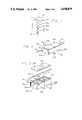
- FIG. 2is a perspective view of the mechanical parts of a preferred embodiment of a thermal transit time flow measurement system utlizing one heater element and one sensor element;
- FIG. 3an exploded view of the system of FIG. 2;
- FIG. 4is an exploded view of a resonant microwave cavity which can be utilized as either the heating element or the sensing element in the embodiment of FIG. 2;
- FIG. 5is a top view of the resonant microwave cavity of FIG. 4;
- FIG. 6is a cross-sectional view of the resonant microwave cavity element of FIG. 5 taken along line 6--6;
- FIG. 7is a schematic diagram of an electrical circuit for a microwave heater subsystem utilizing the resonant microwave cavity of FIG. 4;
- FIG. 8is a schematic diagram of an electrical circuit for a preferred embodiment of a microwave sensor subsystem utilizing a resonant microwave cavity of FIG. 4 and a frequency discriminator;
- FIG. 9is a graph representing the output signal of the sensor subsystem of FIG. 8 as a function of the oscillating frequency of the sensing microwave cavity;
- FIG. 10is a graph representing a typical output signal of the sensor subsystem as a function of time, illustrating the detection of passage of a thermal marker
- FIG. 11is a schematic illustration of an alternative embodiment of a microwave heater subsystem comprising a tapered waveguide and associated electrical circuitry;
- FIG. 12is a schematic diagram of an electrical circuit for an alternative embodiment of a microwave sensor subsystem utilizing a resonant microwave cavity of FIG. 4 and an amplitude detector;
- FIG. 13is a schematic diagram of an electrical circuit for a further alternative embodiment of a microwave sensor subsystem utilizing a resonant microwave cavity of FIG. 4 and a phase detector;
- FIG. 14is a schematic diagram of an alternative embodiment of a thermal transit time flow measurement system utilizing infrared sensors
- FIG. 15is a perspective view of a further alternate embodiment of the thermal transit time flow measurement system, in conjunction with a peristaltic fluid pumping system.
- the inventionis embodied in an apparatus for measuring the rate of flow of a fluid through a conduit without direct contact with the fluid, comprising at least one heater means for generating a heat pulse in the fluid flow, and at least one sensor means for detecting the heat pulse in the conduit. Means are also provided for analyzing the output signals of the sensor means for determining the mean velocity or the volumetric rate of flow.
- the heater means and the sensor meansare placed externally in close proximity to, or adjacent to the fluid conduit.
- a microwave heateris provided for rapid generation of heat pulses in the fluid, and the sensor means includes a microwave cavity.
- the sensor meansis responsive to perturbation of the resonant characteristics of the microwave cavity caused by temperature changes of fluid in the conduit, for a rapid and precise determination of travel of the heat pulse in the conduit.
- a series of heat sensor elementsare placed in an array downstream of the heater means to provide flow rate data at a wide range of flow rates.
- the heat pulse sensor meansmay comprise externally placed infrared sensors, or externally placed microwave radiometers which are also responsive to temperature changes of the fluid.
- the technique of the present inventionprovides a system of fluid flow measurement which is highly independent of fluid temperature and pressure, ambient temperature and pressure, fluid composition, fluid viscosity, and fluid specific heat, provided that the flow is substantially laminar and Newtonian.
- an apparatusfor measuring the rate of flow of a fluid through a conduit, comprising at least one heater means for generating radiative heat energy in the fluid flow sufficient to produce a thermal marker in the fluid flow, the heater means being disposed external to the conduit; at least one sensor means for detecting the thermal marker in the fluid disposed external to the conduit, and adapted to generate an electrical signal responsive to the proximity of the thermal marker to the sensor means; and signal processing means operatively connected to the heater means and the sensor means for determining a parameter of the rate of fluid flow within the conduit responsive to the signal from the sensor means.
- the inventionis a thermal transit time flow measurement system and apparatus, which is described by way of example as being operable in conjunction with a system for infusing intravenous fluid through a tube to a patient.
- the inventionis also useful for measuring fluid flow through conduits generally, such as for urine flow or blood flow, in industrial drug manufacturing processes, or in other similar medical, scientific and industrial applications.
- a disposable IV setis shown as having a tube 10, with an exterior surface 11, and contains a fluid infusate. The basic measurement procedure involves heating of a specific region of fluid within the infusate stream and timing its movement downstream.
- radiative heating provided by a single microwave heater 12generates the heat pulse or thermal marker 16, and one or more microwave sensing elements 14a, b, c are positioned outside the fluid conduit, such that the fluid conduit passes through or adjacent to them downstream from the microwave heater, with the heating and sensing being provided without direct fluid contact.
- Heatingis preferably accomplished by exposing the infusate to microwave radiation for a period of from 0.1 to 20 seconds.
- the temperature rise in the vicinity of the thermal markerdepends upon heater power, flow rate, heat pulse duration, heater efficiency, fluid specific heat, and other factors, but generally a typical temperature rise of an intravenous fluid infusate will be on the order of a few degrees centigrade in the warmed zone.
- Flow rateis related to the time interval during which the warmed zone moves from the heater to a sensor, or from one sensor to another sensor as the fluid moves downstream.
- either two or more sensor elements or two or more heater elementsare preferably used, although it is only necessary to provide one such heater and one such sensor.
- sensor elements further from the heaterwill provide the primary flow rate data, whereas at lower flow rates, those elements nearer the heater will provide the primary data. This is due to the fact that at low flow rates heat energy in the warmed zone will dissipate before the heated region approaches the far sensor array elements, while at high flow rates, the near elements will detect the heated zone too soon after the beginning of the onset of the heater pulse to provide accurate information.
- An alternative to a plurality of sensors downstreamwould be a plurality of heaters upstream, with selection of a particular heater being determined as approriate to an estimated rate of flow.
- the flow measurement system of the inventioncan function equally well within an infusion controller device which relies on the force of gravity to move fluid and does not involve a pumping mechanism. Because the flow measurement system provides feedback to control the infusion instrument, the pump or controller mechanism used in such a system need not be as accurate as that required in a conventional open loop design.
- the passage of a heat pulse 16is apparent by monitoring the resonant frequencies of one or more microwave thermal sensors 14a, b, and c, disposed external to the conduit, downstream from the heater element.
- the sensor element 14a nearest the heater 12may detect the heated zone too soon after the onset of the microwave heating pulse to provide accurate flow rate information; therefore the furthest sensor element 14c would be utilized.
- the nearest sensor element 14awill provide better detection of the thermal maker, which disperses as it propogates downstream.
- the preferred sensor for detecting a change in the temperature of the infusatecomprises a low energy microwave device having a resonant microwave cavity encompassing a region of interest in the tube containing infusate.
- FIGS. 2 and 3illustrate the mechanical components of a thermal transit time flow measurement system utilizing two microwave cavities, one for heating and one for sensing. For the sake of simplicity, these cavities are shown adjacent to one another, of equal size and having a rectangular shape, though other shapes, such as cylindrical, and other sizes, could be employed. It is not necessary that the heater cavity 17 and sensor cavity 21 be identical. In systems with multiple sensor cavities and/or multiple heater cavities, each cavity may have a unique geometry.
- the fluid conduit 10enters the heater cavity housing 18 and exits from the sensor cavity housing 22.
- Both cavitiesare substantially closed spaces with electrically conductive inner surfaces.
- the heater cavity shapeis defined by the heater cavity housing 18 and the heater cavity cover 20.
- the sensor cavity shapeis defined by the sensor cavity housing 22 and the sensor cavity cover 24.
- the cavity coverswhich are necessary for enclosure of the cavity space, also shield the cavities.
- the microwave heateris operated as a single-mode or dominant mode resonant cavity in which the microwave energy is significantly confined.
- the full enclosure of the cavitiesprevents energy from impinging on objects external to the cavities, and in the case of the sensor subsystem, this shielding also prevents energy from outside of the cavity from interfering with sensor operation.
- Each cavityalso includes two electrical ports, one for coupling microwave energy into the cavity from external circuitry, and the other for coupling microwave energy out of the cavity to external circuitry.
- the input cable 26 to the heater cavityconveys energy into the cavity, and the output cable 28 from the heater cavity conveys energy out of the cavity.
- Corresponding input and output cables 30 and 32convey energy into and out of the sensor
- the heater focusing post 34 and the sensor focusing post 36are both visible.
- the postswhich have electrically conductive surfaces, focus the electric field present within the cavities and are critical to operation of the preferred embodiment of the invention.
- FIGS. 4, 5, and 6illustrate a resonant microwave cavity which may be utilized for either the heater subsystem or the sensor subsystem.
- the rectangular form of the microwave cavity 37is defined by the cavity housing 38 and the cavity cover 40.
- the microwave cavityhas an input cable 42 which terminates in an input coupling loop 44, located within the internal cavity space, and an output cable 46 which is fed by an output coupling loop 48, also located within the internal cavity space.
- the cavityitself has a primary resonant mode, the frequency of which depends on the cavity's specific dimensions and geometry. When the cavity is resonating in its primary mode by means of energy introduced at the proper frequency by the input coupling loop, there will exist a region of high electric field density located in the gap between the focusing post 50 and the cavity cover 40.
- a portion of the fluid conduitis positioned within the gap.
- the focusing postneed not be shaped as shown and need not be located in the center of the cavity; however, at no point does the surface of the focusing post contact the cavity cover.
- the resonant frequency of the cavityis affected by its shape and by the location, shape, and size of the focusing post, as well as by the distance between the top surface of the post and the lower surface of the cavity cover. Methods of field concentration similar to this are well-known to those skilled in the art, and any effective means of generating a focused electric field impinging on a specific region of the conduit within the cavity may be employed.
- the microwave heater cavity 17, illustrated in FIG. 7 with its cavity cover removed,has an input port 52, which allows the heater input cable 26 to enter the cavity, and an output port 54 which allows the heater output cable 28 to exit the cavity.
- the input cable 26is terminated by the heater input coupling loop 56 through which microwave energy used for radiative heating is introduced into the cavity from external circuitry.
- the output cable 28is fed by the heater output coupling loop 58 which couples a small amount of electromagentic energy out of the heater cavity to external circuitry.
- the heater circuitcan be described as a power oscillator, with the cavity itself being the resonant component of the circuit. Energy introduced into the heater cavity via the input coupling loop establishes an electric field in the gap between the heater focusing post and the heater cavity cover.
- the heatercan be switched on and off by means of the microwave switch 60, which is controlled by a heater pulse 62, heating occurring whenever the microwave switch is closed.
- the phase shift element 64is necessary to provide the appropriate phase shift to support oscillation at the primary resonant mode of the cavity, and can be a delay element or a reactive component with the appropriate phase characteristic.
- the power amplifier 66provides the necessary loop gain and power to support oscillation at a power level appropriate to heat the fluid.
- the oscillator circuitis completed by the connection from microwave switch to the power amplifier provided by cable or wiring 68.
- the fluid conduitpasses through the cavity and heating occurs in the gap between the focusing post and the cavity cover.
- Alternative designs for circuitry associated with the microwave heaterare also possible.
- a resonant microwave cavitywhich encompasses a portion of the conduit containing the fluid, and is thus loaded by the electromagnetic properties of the fluid within, may be employed as a sensor capable of detecting the passage of a thermal marker.
- Circuitry associated with the resonant microwave sensing cavitymust be sensitive to changes in the cavity's resonant characteristics in order to indicate passage of the thermal marker.
- the electromagnetic properties of the fluid conduit itselfalso play a part in the behavior of a sensor of the preferred embodiment because the sensor, regardless of exactly how it functions, must encompass the conduit, and the conduit wall material therefore influences the electromagnetic field within the sensor cavity.
- the microwave sensor cavityhas an input port 70, which allows the sensor input cable 30 to enter the cavity, and an output port 72 which allows the sensor output cable 32 to exit the cavity.
- the input cableis terminated by the sensor input coupling loop 76 through which a small amount of microwave energy, not intended to cause fluid heating, is introduced into the cavity from external circuitry.
- the output cable 32is fed by the sensor output coupling loop 78 which couples a small amount of electromagnetic energy out of the sensor cavity to the external circuitry.
- the sensor subsystemconsists of two major subcircuits, a low power microwave oscillator 80 and a frequency discriminator 82.
- the microwave oscillatorcauses the sensor cavity to resonate in its primary mode and thus establishes an electric field within the gap between the sensor focusing post 36 and the sensor cavity cover. A portion of this energy is coupled into the frequency discriminator subcircuit 82 by means of a 2-way power divider 83. Variations in the output signal of the frequency discriminator 82 indicate changes in the resonant frequency of the sensor cavity. Because the fluid's complex dielectric constant is influenced by temperature, and the cavity's resonance is in turn perturbed by changes in the dielectric constant of the fluid within, the passage of a thermal marker is thus apparent.
- the oscillator portion 80 of the preferred embodiment of the sensor circuitrycomprises the microwave resonant cavity 21, a phase shifting element 84, an amplifier 86, the interconnections 30, 32, 90, and 92, the power divider 83, and the input and output coupling loops, 76 and 78 respectively.
- the phase shifting element 84is necessary to provide the appropriate phase shift to support oscillation at the primary resonant mode of the cavity and can be a delay element or an appropriate reactive component, and the amplifier 86 provides the necessary loop gain to support oscillation.
- the oscillator circuitis completed by the interconnections 32, 90, 92 and 30, and the power divider 83, which couples part of the oscillator signal through cable or wire 94 to the frequency discriminator 82.
- Interconnection 92provides an electrical path from the output of the amplifier 86 to the input of the power divider 83, and interconnection 90 provides a path from the delay element 84 to the input of the amplifier 86.
- the fluid conduitpasses through the cavity, and sensing occurs in the gap between the focusing post 36 and the cavity cover.
- the frequency discriminator portion 82 of the preferred embodiment of the sensor circuitrycontains the input cable or wire 94, another two-way power divider 96, a delay element 98, a mixer with a DC-coupled output 100, a low-pass filter 102, an output cable 104, and the interconnecting cables or wires 106, 108, 110, and 112.
- a portion of the energy from the oscillating resonant cavityis fed into the discriminator via cable or wire 94 and is split by power divider 96 into two signals, one of which is delayed by delay element 98.
- the delayed signalis fed into one input of the mixer 100, either the "RF” or “LO” port, via cable or wire 108, and the other signal, which is not delayed, is fed into the other input, either the "LO” or “RF” port, of the mixer 100 via cable or wire 110.
- the DC-component of the output of the mixeravailable at its "IF” port, indicates changes in the cavity's resonant frequency.
- Low-pass filter 102which is unnecessary if the bandwidth of the mixer is limited, ensures that the output signal at 102 contains only the DC-component of the mixer's output.
- the delay elementis chosen such that the discriminator sensitivity is high in the frequency region of operation.
- a frequency range of high discriminator sensitivity 114is indicated, and a region of low discriminator sensitivity 116 is also indicated.
- Characteristics and limitations of a simple frequency discriminatorsuch as that utilized in the preferred embodiment of the sensor circuitry are well-known to those familiar with the art.
- the resonant characteristics of the cavitychange, due to the loading of the cavity by th encompassed fluid and the dependence of the fluid's dielectric constant on temperature, and consequently the frequency of the oscillator portion of the sensor circuitry changes.
- the oscillator portion of the circuitintroduces a very small amount of energy into the sensor cavity which, in effect, "interrogates” the cavity in order to determine its resonant characteristics, yet the energy level is too small to cause significant heating of the fluid.
- the changes in oscillator frequency caused by the passage of the thermal markerare detected by the discriminator portion of the sensor circuitry, resulting in a change in the discriminator's output signal.
- the microwave heateris active.
- the sensor outputis at a maximum, and the time from initial activation of the heater to this peak can be considered to be the thermal transit time of the resulting heat pulse.
- FIG. 12An alternative embodiment of the electrical circuitry associated with the microwave sensor cavity element is illustrated in FIG. 12.
- the resonant microwave sensor cavityfunctions as a filter, receiving its input energy from a low-level microwave signal source 201 via input cable 30.
- Signal source 201operates near the resonant frequency of the sensor cavity, and this energy, in effect, "interrogates" the cavity to determine its resonant characteristics.
- the output cable from the sensor cavity 32feeds a small portion of electromagnetic energy out of the sensor cavity and into an amplitude detector 207.
- the response of the cavity to the low-level energy introduced by the signal sourcechanges. This change is apparent at the output of the amplitude detector 207.
- FIG. 13A further alternate embodiment of the electrical circuitry associated with the microwave sensor cavity element is illustrated in FIG. 13.
- the sensor cavityis functioning as a filter, however in this case the phase, rather than the amplitude, is the parameter of interest.
- Signal source 201generates low-level microwave energy which if fed via interconnection 203 to the input of two-way power divider 202. A portion of this low-level energy is fed into the sensor cavity via input cable 30 and another portion is fed to one input of a phase detector 206 via interconnection 204.
- the output cable of the sensor cavity 32feeds a small portion of electromagnetic energy out of the sensor cavity into the other input of the phase detector 206.
- the phase detector's outputindicates differences in phase between the filtered and unfiltered microwave signals.
- FIG. 11An alternative type of microwave heater subsystem of the tapered waveguide type is illustrated in FIG. 11.
- Microwave energyis fed into the waveguide 122 from feed 124 on one side of the waveguide, and energy is directed to the opposite side of the waveguide in such a manner that the electric field is concentrated at the region of heating 126 of the fluid within the conduit.
- a preferred embodiment of the electrical circuit associated with the tapered waveguide heaterconsists of an oscillator 128, the output of which is fed through a microwave switch 60 and then fed into a microwave power amplifier 130. The output of the amplifier is fed into the waveguide via the input feed line 124. This heater can be switched on and off by means of the microwave switch 60, which is controlled by an electrical signal 62.
- the waveguide dimensions and the oscillator frequencyare chosen such that a high electric field density exists in the region of heating.
- FIG. 14Another alternative embodiment of a heat sensor which may be utilized within the flow measuring apparatus of the present invention is illustrated in FIG. 14, showing three infrared sensors 132a, b, and c. Also shown in the figure are focusing elements 134a, b, and c, associated with each infrared sensor, illustrated for the sake of simplicity as being pinhole structures.
- the electrical signals supplied by the sensor or sensors in the thermal transit time flow measurement system of the present inventionmust be processed or analyzed in order to determine fluid flow rate.
- this signal processingis implemented by microprocessor means.
- the control of the heater subsystemis implemented by microprocessor means, which enable and disable the heater at specific times.
- the signal processing and heater control requirements of the present inventiondo not represent a large extra cost burden.
- the integral microprocessorperforms many computational and control tasks, including communications with the operator of the instrument, allowing the operator to choose the desired flow rate, and control of the pumping mechanism.
- this same microprocessorcan also perform the heater control and sensor signal processing tasks. Additionally, the microprocessor can be involved with the closed loop control of the infusion instrument, thereby maintaining a desired flow rate.
- a microprocessor meanscan analyze the signals from the sensor array elements, and trigger the heat pulses used by the flow measurement system.
- the alogrithm used by the microprocessor meanscan be adapted to be responsive to the heat sensor elements, and the repetition rate of heating pulses may also be adapted, as may the power and/or duration of the individual heat pulses, depending upon flow rate.
- the signal processing algorithmsmay take a wide variety of possible forms as are known in the art. For example, an algorithm can compare the transit times of the heat pulses, along the distance from the point of their generation to the sensor, with reference times for a corresponding distance at standardized flow rates, and calculate the actual flow rate.
- the instrumentmight have standard times and flow rates pre-programmed to correspond to the particular type of conduit to be utilized in the instrument, or the instrument might be pre-programmed with reference standards for several different types of conduit.
- the signal processingcould also be simply used to monitor changes in the flow rate, once the proper flow rate has been set, without the need to calculate absolute flow rates.
- An algorithmcould monitor extremes of flow rates, thereby triggering an alarm in the event of dangerous situations such as blockage of flow, or a disconnected line, or other similar situations.
- the signal processingmay also, for example, be used in connection with flow rate feedback and control systems, for active control of IV administration or an industrial process.
- a preferred method of signal processingis to incorporate within the microprocessor memory a look-up table that relates the features of the sensor signals to the flow rate range and to utilize the microprocessor to interpolate between table entries to derive flow rates intermediate to values within the look-up table.
- the range of flow rates measurable by means of the present inventionmay be extended by providing more than one sensor element or more than one heater element. As described above, there will be a very low rate regime in which the best results are obtained by using the most closely spaced heater-sensor pair. Conversely, the most widely spaced heater-sensor pair will provide the best results at high flow rates.
- To extend the flow rate range of the present invention to lower flow ratesit is therefore necessary to place the active sensor as close to the active heater as practical, and also to employ an energetic heat pulse, both of these actions causing a greater temperature rise in the thermal marker as it passes through the sensor.
- Increasing the power of the heater subsystemhas the effect of producing a more energetic heat pulse, as does lengthening the duration of the control signal that controls the heater pulse. Lengthening the duration of the heat pulse has an adverse effect on the number of discrete flow rate measurements that can be made over a given period of time; however, in many applications, including infusion in a medical setting, the flow rate is generally slowly varying.
- two or more sensor elementsmay detect the warmed zone.
- the signals from several sensor elementscan be correlated to provide a higher degree of measured flow rate accuracy than would be possible with only one element.
- techniquessuch as digital filtering and ensemble averaging may also be used.
- FIG. 15shows a further embodiment of the thermal transit time flow measurement system which is well-suited for measurement of flow rate in a medical fluid delivery system.
- An enclosure 136houses the pump mechanism 138, illustrated as a peristaltic type device for simplicity, a microwave heater cavity body 140, positioned and adapted to receive the fluid conduit, and a microwave sensor cavity body 142, also positioned and adapted to receive the fluid conduit.
- Corresponding covers 144 for the heater element and 146 for the sensor elementare mounted in mating relationship with the heater element and sensor element on a hinged door 148.
- the flow rate measurement apparatus of the inventionprovides a simple, cost effective, accurate way of measuring fluid flow in a conduit, without fluid contact, and which can also provide accurate flow measurements over a wide range of flow rates for a wide variety of fluids and environmental conditions.
- other forms of radiative heating and sensing with similar characteristics of rapid heating and rapid heat sensingmay be suitable alternatives.
- infrared energycould also be used to heat the fluid. This energy could be derived from a laser and applied by means of fiber optics and/or infrared lenses for focusing.
- Alternative sensing elementsinclude infrared radiation sensing elements or detectors of microwave energy radiated by the thermal marker as it progresses downstream.
- the flow rate measurement apparatus of the inventionis useful for measuring fluid flow through conduits in a variety of medical, scientific and industrial applications.
Landscapes
- Physics & Mathematics (AREA)
- Fluid Mechanics (AREA)
- General Physics & Mathematics (AREA)
- Measuring Volume Flow (AREA)
Abstract
Description
Claims (29)
Priority Applications (5)
| Application Number | Priority Date | Filing Date | Title |
|---|---|---|---|
| US07/319,353US4938079A (en) | 1989-03-06 | 1989-03-06 | Thermal transit time flow measurement system |
| EP90104184AEP0386670B1 (en) | 1989-03-06 | 1990-03-05 | Thermal transit time flow measurement system |
| JP2053471AJPH0781894B2 (en) | 1989-03-06 | 1990-03-05 | Flow measuring device |
| DE69022449TDE69022449T2 (en) | 1989-03-06 | 1990-03-05 | Flow measuring system based on the thermal runtime principle. |
| CA002011439ACA2011439C (en) | 1989-03-06 | 1990-03-05 | Thermal transit time flow measurement system |
Applications Claiming Priority (1)
| Application Number | Priority Date | Filing Date | Title |
|---|---|---|---|
| US07/319,353US4938079A (en) | 1989-03-06 | 1989-03-06 | Thermal transit time flow measurement system |
Publications (1)
| Publication Number | Publication Date |
|---|---|
| US4938079Atrue US4938079A (en) | 1990-07-03 |
Family
ID=23241895
Family Applications (1)
| Application Number | Title | Priority Date | Filing Date |
|---|---|---|---|
| US07/319,353Expired - LifetimeUS4938079A (en) | 1989-03-06 | 1989-03-06 | Thermal transit time flow measurement system |
Country Status (5)
| Country | Link |
|---|---|
| US (1) | US4938079A (en) |
| EP (1) | EP0386670B1 (en) |
| JP (1) | JPH0781894B2 (en) |
| CA (1) | CA2011439C (en) |
| DE (1) | DE69022449T2 (en) |
Cited By (72)
| Publication number | Priority date | Publication date | Assignee | Title |
|---|---|---|---|---|
| US5026171A (en)* | 1989-06-07 | 1991-06-25 | Feller Murray F | Apparatus for flow rate and energy transfer measurements |
| WO1991019170A1 (en)* | 1990-06-04 | 1991-12-12 | Mcpherson's Limited | Flow sensor and control system |
| US5198776A (en)* | 1991-06-26 | 1993-03-30 | Microwave Medical Systems, Inc. | Microwave system for detecting gaseous emboli |
| US5260665A (en)* | 1991-04-30 | 1993-11-09 | Ivac Corporation | In-line fluid monitor system and method |
| WO1995002164A1 (en)* | 1993-07-07 | 1995-01-19 | Ic Sensors, Inc. | Pulsed thermal flow sensor system |
| US5455565A (en)* | 1993-11-08 | 1995-10-03 | Ivac Corporation | Fluid monitor system and method using a resonator |
| EP0767360A3 (en)* | 1995-10-06 | 1997-12-17 | Lovejoy Controls Corporation | Microwave thermal trace flowmeter |
| US5741979A (en)* | 1995-11-09 | 1998-04-21 | The United States Of America As Represented By The Administrator Of National Aeronautics And Space Adminstrator | Particle velocity measuring system |
| US5764539A (en)* | 1994-01-21 | 1998-06-09 | Novartis Nutrition Ag | Non-invasive system and method for a fluid flow monitoring system |
| US5803917A (en)* | 1994-09-13 | 1998-09-08 | Alaris Medical Systems, Inc. | Fluid flow resistance monitoring system |
| US6158965A (en)* | 1996-07-30 | 2000-12-12 | Alaris Medical Systems, Inc. | Fluid flow resistance monitoring system |
| US6213972B1 (en) | 1994-09-13 | 2001-04-10 | Alaris Medical Systems, Inc. | Fluid flow resistance monitoring system |
| US6289746B1 (en)* | 1998-05-25 | 2001-09-18 | Industrial Technology Research Institute | Thermal pulsed micro flow sensor |
| US6386050B1 (en) | 1999-12-21 | 2002-05-14 | Agilent Technologies, Inc. | Non-invasive fluid flow sensing based on injected heat tracers and indirect temperature monitoring |
| US20020147425A1 (en)* | 1997-06-12 | 2002-10-10 | Briggs Kenneth D. | Temperature compensation system for regulating flow through tubing in a pump |
| US20030043882A1 (en)* | 2001-08-29 | 2003-03-06 | Stefan Burger | Arrangement for picking up and/or setting down, and method of detecting, movable components |
| US20030213297A1 (en)* | 2002-05-15 | 2003-11-20 | Sage Burton H. | Liquid metering system |
| US20050005710A1 (en)* | 2002-05-15 | 2005-01-13 | Therafuse, Inc. | Liquid metering system |
| US20050059926A1 (en)* | 2003-09-16 | 2005-03-17 | Therafuse, Inc. | Compensating liquid delivery system and method |
| DE10356443A1 (en)* | 2003-12-03 | 2005-07-07 | Digmesa Ag | Method and device for non-contact measuring of flow rates |
| US20060020255A1 (en)* | 2004-05-28 | 2006-01-26 | Cassidy David E | Flow control in an intravenous fluid delivery system |
| US20080210002A1 (en)* | 2004-09-07 | 2008-09-04 | Shoji Kamiunten | Flow Sensor |
| US20090101550A1 (en)* | 2007-10-22 | 2009-04-23 | Baxter International Inc. | Dialysis system having non-invasive fluid velocity sensing |
| US20090157040A1 (en)* | 2007-12-17 | 2009-06-18 | Hospira, Inc. | Differential pressure based flow sensor assembly for medication delivery monitoring and method of using the same |
| EP2090869A1 (en)* | 2008-02-14 | 2009-08-19 | Surpass Industry Co., Ltd. | Flow rate measuring method and device |
| US20090288497A1 (en)* | 2008-05-23 | 2009-11-26 | Hospira, Inc. | Cassette for differential pressure based medication delivery flow sensor assembly for medication delivery monitoring and method of making the same |
| US20100057058A1 (en)* | 2008-09-02 | 2010-03-04 | Hospira, Inc. | Cassette for use in a medication delivery flow sensor assembly and method of making the same |
| US20100114027A1 (en)* | 2008-11-05 | 2010-05-06 | Hospira, Inc. | Fluid medication delivery systems for delivery monitoring of secondary medications |
| US20100198155A1 (en)* | 2009-01-30 | 2010-08-05 | Hospira, Inc. | Cassette for differential pressure based medication delivery flow sensor assembly for medication delivery monitoring and method of making the same |
| US20100280486A1 (en)* | 2009-04-29 | 2010-11-04 | Hospira, Inc. | System and method for delivering and monitoring medication |
| US7908931B1 (en)* | 2009-12-14 | 2011-03-22 | Cosense, Inc. | Non invasive flow rate measuring system and method |
| WO2012148356A1 (en)* | 2011-04-27 | 2012-11-01 | Freddie Eng Hwee Lee | Intravenous infusion monitoring apparatus, system and method |
| US20130014569A1 (en)* | 2009-12-18 | 2013-01-17 | Waters Technologies Corporation | Thermal-based flow sensing apparatus and method for high-performance liquid chromatography |
| US8529490B2 (en) | 2002-04-10 | 2013-09-10 | Baxter International Inc. | Systems and methods for dialysis access disconnection |
| US20140048558A1 (en)* | 2011-04-27 | 2014-02-20 | Freddie Eng Hwee Lee | Fluid delivery apparatus |
| US8708946B2 (en) | 2002-04-10 | 2014-04-29 | Baxter International Inc. | Access disconnection systems using conductive contacts |
| WO2014070112A1 (en) | 2012-10-31 | 2014-05-08 | Lee Eng Hwee Freddie | Intravenous (iv) infusion monitoring method and system |
| US8920356B2 (en) | 2002-04-10 | 2014-12-30 | Baxter International Inc. | Conductive polymer materials and applications thereof including monitoring and providing effective therapy |
| US20150273144A1 (en)* | 2012-10-31 | 2015-10-01 | Eng Hwee Freddie LEE | Intravenous (iv) infusion monitoring method and system |
| US9995611B2 (en) | 2012-03-30 | 2018-06-12 | Icu Medical, Inc. | Air detection system and method for detecting air in a pump of an infusion system |
| US10022498B2 (en) | 2011-12-16 | 2018-07-17 | Icu Medical, Inc. | System for monitoring and delivering medication to a patient and method of using the same to minimize the risks associated with automated therapy |
| US10046112B2 (en) | 2013-05-24 | 2018-08-14 | Icu Medical, Inc. | Multi-sensor infusion system for detecting air or an occlusion in the infusion system |
| WO2018154407A1 (en)* | 2017-02-23 | 2018-08-30 | Onefusion Ag | Perfusion systems and flow sensors for use with perfusion systems |
| US10143795B2 (en) | 2014-08-18 | 2018-12-04 | Icu Medical, Inc. | Intravenous pole integrated power, control, and communication system and method for an infusion pump |
| US10155082B2 (en) | 2002-04-10 | 2018-12-18 | Baxter International Inc. | Enhanced signal detection for access disconnection systems |
| US10166328B2 (en) | 2013-05-29 | 2019-01-01 | Icu Medical, Inc. | Infusion system which utilizes one or more sensors and additional information to make an air determination regarding the infusion system |
| US10247635B2 (en)* | 2016-06-30 | 2019-04-02 | Hach Company | Online chlorine analyzer |
| US20190199040A1 (en)* | 2017-12-26 | 2019-06-27 | Sumitomo Wiring Systems, Ltd. | Connector |
| US10342917B2 (en) | 2014-02-28 | 2019-07-09 | Icu Medical, Inc. | Infusion system and method which utilizes dual wavelength optical air-in-line detection |
| US10430761B2 (en) | 2011-08-19 | 2019-10-01 | Icu Medical, Inc. | Systems and methods for a graphical interface including a graphical representation of medical data |
| US10463788B2 (en) | 2012-07-31 | 2019-11-05 | Icu Medical, Inc. | Patient care system for critical medications |
| US10508966B2 (en) | 2015-02-05 | 2019-12-17 | Homeserve Plc | Water flow analysis |
| US10596316B2 (en) | 2013-05-29 | 2020-03-24 | Icu Medical, Inc. | Infusion system and method of use which prevents over-saturation of an analog-to-digital converter |
| US10635784B2 (en) | 2007-12-18 | 2020-04-28 | Icu Medical, Inc. | User interface improvements for medical devices |
| US10656894B2 (en) | 2017-12-27 | 2020-05-19 | Icu Medical, Inc. | Synchronized display of screen content on networked devices |
| US10704979B2 (en) | 2015-01-07 | 2020-07-07 | Homeserve Plc | Flow detection device |
| WO2020171413A1 (en)* | 2019-02-22 | 2020-08-27 | 한국기계연구원 | Flow meter for electric drug injection pump and method for measuring flow using same |
| US10850024B2 (en) | 2015-03-02 | 2020-12-01 | Icu Medical, Inc. | Infusion system, device, and method having advanced infusion features |
| US10918787B2 (en) | 2015-05-26 | 2021-02-16 | Icu Medical, Inc. | Disposable infusion fluid delivery device for programmable large volume drug delivery |
| US11135360B1 (en) | 2020-12-07 | 2021-10-05 | Icu Medical, Inc. | Concurrent infusion with common line auto flush |
| USD939079S1 (en) | 2019-08-22 | 2021-12-21 | Icu Medical, Inc. | Infusion pump |
| US11213619B2 (en) | 2013-11-11 | 2022-01-04 | Icu Medical, Inc. | Thermal management system and method for medical devices |
| US11246985B2 (en) | 2016-05-13 | 2022-02-15 | Icu Medical, Inc. | Infusion pump system and method with common line auto flush |
| US11278671B2 (en) | 2019-12-04 | 2022-03-22 | Icu Medical, Inc. | Infusion pump with safety sequence keypad |
| US11324888B2 (en) | 2016-06-10 | 2022-05-10 | Icu Medical, Inc. | Acoustic flow sensor for continuous medication flow measurements and feedback control of infusion |
| US20220160977A1 (en)* | 2019-03-29 | 2022-05-26 | Fisher & Paykel Healthcare Limited | Systems and methods of detecting incorrect connections in a humidification system |
| US11344668B2 (en) | 2014-12-19 | 2022-05-31 | Icu Medical, Inc. | Infusion system with concurrent TPN/insulin infusion |
| US11344673B2 (en) | 2014-05-29 | 2022-05-31 | Icu Medical, Inc. | Infusion system and pump with configurable closed loop delivery rate catch-up |
| US11883361B2 (en) | 2020-07-21 | 2024-01-30 | Icu Medical, Inc. | Fluid transfer devices and methods of use |
| USD1052728S1 (en) | 2021-11-12 | 2024-11-26 | Icu Medical, Inc. | Medical fluid infusion pump |
| US12350233B2 (en) | 2021-12-10 | 2025-07-08 | Icu Medical, Inc. | Medical fluid compounding systems with coordinated flow control |
| USD1091564S1 (en) | 2021-10-13 | 2025-09-02 | Icu Medical, Inc. | Display screen or portion thereof with graphical user interface for a medical device |
Families Citing this family (10)
| Publication number | Priority date | Publication date | Assignee | Title |
|---|---|---|---|---|
| KR960001601B1 (en)* | 1992-01-23 | 1996-02-02 | 삼성전자주식회사 | Contact hole embedding method and structure of semiconductor device |
| DE4127675C2 (en)* | 1991-08-21 | 1996-08-14 | Elbau Elektronik Bauelemente G | Method and device for monitoring the flow of a fluid in a line, in particular for infusion systems |
| US5525040A (en)* | 1994-03-31 | 1996-06-11 | B&B Financial Planning Inc. | Controller for oil wells with a thermal dispersion probe |
| JP2001272261A (en)* | 2000-03-27 | 2001-10-05 | Tokico Ltd | Flow velocity measuring device and flow meter |
| GB0011387D0 (en)* | 2000-05-12 | 2000-06-28 | Roke Manor Research | Method and apparatus for measuring flow rates |
| KR20020080291A (en)* | 2002-08-28 | 2002-10-23 | (주)글로벌뉴스 | An eye bandage giving off a scent |
| US6695470B1 (en)* | 2002-09-10 | 2004-02-24 | Delphi Technologies, Inc. | Apparatus and method for viscosity measurement |
| JP5024920B2 (en)* | 2005-12-15 | 2012-09-12 | 国立大学法人電気通信大学 | Flow measuring device and method |
| JP4935225B2 (en)* | 2006-07-28 | 2012-05-23 | 株式会社島津製作所 | Electronic component assembly |
| US8656770B2 (en)* | 2011-06-30 | 2014-02-25 | Baker Hughes Incorporated | Electromagnetically heated thermal flowmeter for wellbore fluids |
Citations (21)
| Publication number | Priority date | Publication date | Assignee | Title |
|---|---|---|---|---|
| US2792548A (en)* | 1945-05-28 | 1957-05-14 | Rca Corp | Systems and methods of gas analysis |
| US3019647A (en)* | 1957-08-30 | 1962-02-06 | Honeywell Regulator Co | Electrical fluid-flow measuring apparatus |
| US3807228A (en)* | 1971-11-02 | 1974-04-30 | Gulf Research Development Co | Ultrasonic velocity and mass flowmeter |
| SU533826A1 (en)* | 1975-05-26 | 1976-10-30 | Ленинградский Ордена Трудового Красного Знамени Технологический Институт Им.Ленсовета | Fluid flow meter |
| US4014206A (en)* | 1975-03-31 | 1977-03-29 | Akron City Hospital | Apparatus and method for monitoring air emboli during extracorporeal circulation |
| US4043195A (en)* | 1975-03-13 | 1977-08-23 | Hunting Curtis J | Digital thermodynamic flow-meter |
| US4228683A (en)* | 1975-06-19 | 1980-10-21 | Bayer Aktiengesellschaft | Method of determining liquid flow in a conduit |
| US4234844A (en)* | 1977-05-02 | 1980-11-18 | Near Field Technology Co. | Electromagnetic noncontacting measuring apparatus |
| US4237730A (en)* | 1978-09-15 | 1980-12-09 | Selas Corporation Of America | Fluid velocity measurement system |
| US4255968A (en)* | 1979-06-08 | 1981-03-17 | Intek, Inc. | Flow indicator |
| US4384578A (en)* | 1981-04-16 | 1983-05-24 | The United States Of America As Represented By The Administrator Of The National Aeronautics And Space Administration | Bio-medical flow sensor |
| US4458709A (en)* | 1980-03-27 | 1984-07-10 | Binks Manufacturing Company | Method and apparatus for measuring and controlling fluid flow rates |
| US4480483A (en)* | 1983-04-06 | 1984-11-06 | Westinghouse Electric Corp. | Acousto-optical ultrasonic flowmeter |
| US4483200A (en)* | 1981-01-19 | 1984-11-20 | Anima Corporation | Thermal pulse flowmeter |
| US4491024A (en)* | 1981-07-06 | 1985-01-01 | The Dow Chemical Company | Method for metering sub-10 cc/minute liquid flow |
| US4509974A (en)* | 1982-10-04 | 1985-04-09 | Stauffer Chemical Company | S-n-Butyl-N,N-diisopropyl thiocarbamate as a selective herbicide in cotton |
| US4532811A (en)* | 1981-07-06 | 1985-08-06 | The Dow Chemical Company | Apparatus for metering sub-10 cc/minute liquid flow |
| US4576182A (en)* | 1981-04-23 | 1986-03-18 | University Of Utah | Method and apparatus for measuring liquid flow |
| US4628743A (en)* | 1981-07-06 | 1986-12-16 | The Dow Chemical Company | Apparatus and method for metering sub-10 cc/minute liquid flow |
| US4684367A (en)* | 1985-04-12 | 1987-08-04 | Meditec Research Associates | Ambulatory intravenous delivery system |
| US4715727A (en)* | 1984-07-05 | 1987-12-29 | M/A-Com, Inc. | Non-invasive temperature monitor |
Family Cites Families (4)
| Publication number | Priority date | Publication date | Assignee | Title |
|---|---|---|---|---|
| JPS49106375A (en)* | 1973-02-09 | 1974-10-08 | ||
| JPS52139463A (en)* | 1976-05-18 | 1977-11-21 | Toshiba Corp | Correlated flow meter |
| FR2600776B1 (en)* | 1986-06-24 | 1988-10-21 | Novatome | DEVICE FOR MEASURING THE SPEED OF LOW-SPEED LIQUID METAL IN A CONDUIT |
| GB8710441D0 (en)* | 1987-05-01 | 1987-06-03 | Medistron Ltd | Medical infusion apparatus |
- 1989
- 1989-03-06USUS07/319,353patent/US4938079A/ennot_activeExpired - Lifetime
- 1990
- 1990-03-05EPEP90104184Apatent/EP0386670B1/ennot_activeExpired - Lifetime
- 1990-03-05DEDE69022449Tpatent/DE69022449T2/ennot_activeExpired - Fee Related
- 1990-03-05JPJP2053471Apatent/JPH0781894B2/ennot_activeExpired - Lifetime
- 1990-03-05CACA002011439Apatent/CA2011439C/ennot_activeExpired - Fee Related
Patent Citations (21)
| Publication number | Priority date | Publication date | Assignee | Title |
|---|---|---|---|---|
| US2792548A (en)* | 1945-05-28 | 1957-05-14 | Rca Corp | Systems and methods of gas analysis |
| US3019647A (en)* | 1957-08-30 | 1962-02-06 | Honeywell Regulator Co | Electrical fluid-flow measuring apparatus |
| US3807228A (en)* | 1971-11-02 | 1974-04-30 | Gulf Research Development Co | Ultrasonic velocity and mass flowmeter |
| US4043195A (en)* | 1975-03-13 | 1977-08-23 | Hunting Curtis J | Digital thermodynamic flow-meter |
| US4014206A (en)* | 1975-03-31 | 1977-03-29 | Akron City Hospital | Apparatus and method for monitoring air emboli during extracorporeal circulation |
| SU533826A1 (en)* | 1975-05-26 | 1976-10-30 | Ленинградский Ордена Трудового Красного Знамени Технологический Институт Им.Ленсовета | Fluid flow meter |
| US4228683A (en)* | 1975-06-19 | 1980-10-21 | Bayer Aktiengesellschaft | Method of determining liquid flow in a conduit |
| US4234844A (en)* | 1977-05-02 | 1980-11-18 | Near Field Technology Co. | Electromagnetic noncontacting measuring apparatus |
| US4237730A (en)* | 1978-09-15 | 1980-12-09 | Selas Corporation Of America | Fluid velocity measurement system |
| US4255968A (en)* | 1979-06-08 | 1981-03-17 | Intek, Inc. | Flow indicator |
| US4458709A (en)* | 1980-03-27 | 1984-07-10 | Binks Manufacturing Company | Method and apparatus for measuring and controlling fluid flow rates |
| US4483200A (en)* | 1981-01-19 | 1984-11-20 | Anima Corporation | Thermal pulse flowmeter |
| US4384578A (en)* | 1981-04-16 | 1983-05-24 | The United States Of America As Represented By The Administrator Of The National Aeronautics And Space Administration | Bio-medical flow sensor |
| US4576182A (en)* | 1981-04-23 | 1986-03-18 | University Of Utah | Method and apparatus for measuring liquid flow |
| US4491024A (en)* | 1981-07-06 | 1985-01-01 | The Dow Chemical Company | Method for metering sub-10 cc/minute liquid flow |
| US4532811A (en)* | 1981-07-06 | 1985-08-06 | The Dow Chemical Company | Apparatus for metering sub-10 cc/minute liquid flow |
| US4628743A (en)* | 1981-07-06 | 1986-12-16 | The Dow Chemical Company | Apparatus and method for metering sub-10 cc/minute liquid flow |
| US4509974A (en)* | 1982-10-04 | 1985-04-09 | Stauffer Chemical Company | S-n-Butyl-N,N-diisopropyl thiocarbamate as a selective herbicide in cotton |
| US4480483A (en)* | 1983-04-06 | 1984-11-06 | Westinghouse Electric Corp. | Acousto-optical ultrasonic flowmeter |
| US4715727A (en)* | 1984-07-05 | 1987-12-29 | M/A-Com, Inc. | Non-invasive temperature monitor |
| US4684367A (en)* | 1985-04-12 | 1987-08-04 | Meditec Research Associates | Ambulatory intravenous delivery system |
Non-Patent Citations (4)
| Title |
|---|
| Hoffman and Miller, "Effect of Non-Newtonian Solutions on the Behavior of the Thermal Pulse Time-Of-Flight Flowmeter", Analytical Chemistry, vol. 56, No. 9, pp. 1682-1685, 1984. |
| Hoffman and Miller, Effect of Non Newtonian Solutions on the Behavior of the Thermal Pulse Time Of Flight Flowmeter , Analytical Chemistry, vol. 56, No. 9, pp. 1682 1685, 1984.* |
| Miller and Small, "Thermal Pulse Time-Of-Flight Liquid Flow Meter", Analytical Chemistry, vol. 54, No. 6, pp. 907-910, 1982. |
| Miller and Small, Thermal Pulse Time Of Flight Liquid Flow Meter , Analytical Chemistry, vol. 54, No. 6, pp. 907 910, 1982.* |
Cited By (136)
| Publication number | Priority date | Publication date | Assignee | Title |
|---|---|---|---|---|
| US5026171A (en)* | 1989-06-07 | 1991-06-25 | Feller Murray F | Apparatus for flow rate and energy transfer measurements |
| WO1991019170A1 (en)* | 1990-06-04 | 1991-12-12 | Mcpherson's Limited | Flow sensor and control system |
| US5260665A (en)* | 1991-04-30 | 1993-11-09 | Ivac Corporation | In-line fluid monitor system and method |
| US5198776A (en)* | 1991-06-26 | 1993-03-30 | Microwave Medical Systems, Inc. | Microwave system for detecting gaseous emboli |
| WO1995002164A1 (en)* | 1993-07-07 | 1995-01-19 | Ic Sensors, Inc. | Pulsed thermal flow sensor system |
| US5455565A (en)* | 1993-11-08 | 1995-10-03 | Ivac Corporation | Fluid monitor system and method using a resonator |
| US5764539A (en)* | 1994-01-21 | 1998-06-09 | Novartis Nutrition Ag | Non-invasive system and method for a fluid flow monitoring system |
| US5803917A (en)* | 1994-09-13 | 1998-09-08 | Alaris Medical Systems, Inc. | Fluid flow resistance monitoring system |
| US6213972B1 (en) | 1994-09-13 | 2001-04-10 | Alaris Medical Systems, Inc. | Fluid flow resistance monitoring system |
| EP0767360A3 (en)* | 1995-10-06 | 1997-12-17 | Lovejoy Controls Corporation | Microwave thermal trace flowmeter |
| US5741979A (en)* | 1995-11-09 | 1998-04-21 | The United States Of America As Represented By The Administrator Of National Aeronautics And Space Adminstrator | Particle velocity measuring system |
| US6158965A (en)* | 1996-07-30 | 2000-12-12 | Alaris Medical Systems, Inc. | Fluid flow resistance monitoring system |
| US20020147425A1 (en)* | 1997-06-12 | 2002-10-10 | Briggs Kenneth D. | Temperature compensation system for regulating flow through tubing in a pump |
| US6869425B2 (en)* | 1997-06-12 | 2005-03-22 | Hospira, Inc. | Temperature compensation system for regulating flow through tubing in a pump |
| US6503221B1 (en)* | 1997-06-12 | 2003-01-07 | Abbott Laboratories | Temperature compensation system for regulating flow through tubing in a pump |
| US6289746B1 (en)* | 1998-05-25 | 2001-09-18 | Industrial Technology Research Institute | Thermal pulsed micro flow sensor |
| US6386050B1 (en) | 1999-12-21 | 2002-05-14 | Agilent Technologies, Inc. | Non-invasive fluid flow sensing based on injected heat tracers and indirect temperature monitoring |
| US20030043882A1 (en)* | 2001-08-29 | 2003-03-06 | Stefan Burger | Arrangement for picking up and/or setting down, and method of detecting, movable components |
| US8708946B2 (en) | 2002-04-10 | 2014-04-29 | Baxter International Inc. | Access disconnection systems using conductive contacts |
| US8529490B2 (en) | 2002-04-10 | 2013-09-10 | Baxter International Inc. | Systems and methods for dialysis access disconnection |
| US8801646B2 (en) | 2002-04-10 | 2014-08-12 | Baxter International Inc. | Access disconnection systems with arterial and venous line conductive pathway |
| US8920356B2 (en) | 2002-04-10 | 2014-12-30 | Baxter International Inc. | Conductive polymer materials and applications thereof including monitoring and providing effective therapy |
| US10155082B2 (en) | 2002-04-10 | 2018-12-18 | Baxter International Inc. | Enhanced signal detection for access disconnection systems |
| US20050050941A1 (en)* | 2002-05-15 | 2005-03-10 | Sage Burton H. | Liquid measuring system |
| US20050005710A1 (en)* | 2002-05-15 | 2005-01-13 | Therafuse, Inc. | Liquid metering system |
| US20030213297A1 (en)* | 2002-05-15 | 2003-11-20 | Sage Burton H. | Liquid metering system |
| US6932796B2 (en)* | 2002-05-15 | 2005-08-23 | Tearafuse, Inc. | Liquid metering system |
| US7268859B2 (en) | 2002-05-15 | 2007-09-11 | Therafuse, Inc. | Liquid measuring system |
| US20050059926A1 (en)* | 2003-09-16 | 2005-03-17 | Therafuse, Inc. | Compensating liquid delivery system and method |
| US7361155B2 (en) | 2003-09-16 | 2008-04-22 | Therafuse, Inc. | Compensating liquid delivery system and method |
| DE10356443A1 (en)* | 2003-12-03 | 2005-07-07 | Digmesa Ag | Method and device for non-contact measuring of flow rates |
| US7377148B2 (en) | 2004-05-28 | 2008-05-27 | Enginivity, Llc | Capacitor-based gas detection in an intravenous fluid delivery system |
| WO2005118051A3 (en)* | 2004-05-28 | 2006-04-27 | Enginivity Llc | Flow control and gas detection and gas removal in an intravenous fluid delivery system |
| US7547295B2 (en) | 2004-05-28 | 2009-06-16 | Enginivity, Llc | Gas removal in an intravenous fluid delivery system |
| US20060025725A1 (en)* | 2004-05-28 | 2006-02-02 | Cassidy David E | Gas removal in an intravenous fluid delivery system |
| US20060021419A1 (en)* | 2004-05-28 | 2006-02-02 | Cassidy David E | Gas detection in an intravenous fluid delivery system |
| US20060020255A1 (en)* | 2004-05-28 | 2006-01-26 | Cassidy David E | Flow control in an intravenous fluid delivery system |
| US7695448B2 (en) | 2004-05-28 | 2010-04-13 | General Electric Company | Flow control in an intravenous fluid delivery system |
| US20080210002A1 (en)* | 2004-09-07 | 2008-09-04 | Shoji Kamiunten | Flow Sensor |
| US7752909B2 (en) | 2004-09-07 | 2010-07-13 | Yamatake Corporation | Flow sensor with non-contact temperature detecting means |
| EP2604301A1 (en) | 2007-10-22 | 2013-06-19 | Baxter International Inc | Dialysis system having non-invasive fluid velocity sensing |
| WO2009055302A3 (en)* | 2007-10-22 | 2009-09-03 | Baxter International Inc. | Dialysis system having non-invasive fluid velocity sensing |
| US20090101550A1 (en)* | 2007-10-22 | 2009-04-23 | Baxter International Inc. | Dialysis system having non-invasive fluid velocity sensing |
| US8858787B2 (en) | 2007-10-22 | 2014-10-14 | Baxter International Inc. | Dialysis system having non-invasive fluid velocity sensing |
| US9724456B2 (en) | 2007-10-22 | 2017-08-08 | Baxter International Inc. | Dialysis system having non-invasive fluid velocity sensing |
| US20090157040A1 (en)* | 2007-12-17 | 2009-06-18 | Hospira, Inc. | Differential pressure based flow sensor assembly for medication delivery monitoring and method of using the same |
| US8403908B2 (en) | 2007-12-17 | 2013-03-26 | Hospira, Inc. | Differential pressure based flow sensor assembly for medication delivery monitoring and method of using the same |
| US9272089B2 (en) | 2007-12-17 | 2016-03-01 | Hospira, Inc. | Differential pressure based flow sensor assembly for medication delivery monitoring and method of using the same |
| US10635784B2 (en) | 2007-12-18 | 2020-04-28 | Icu Medical, Inc. | User interface improvements for medical devices |
| US7856892B2 (en)* | 2008-02-14 | 2010-12-28 | Surpass Industry Co, Ltd. | Flow-rate measuring method and flow-rate measuring device |
| US20090205441A1 (en)* | 2008-02-14 | 2009-08-20 | Surpass Industry Co., Ltd. | Flow-Rate Measuring Method and Flow-Rate Measuring Device |
| EP2090869A1 (en)* | 2008-02-14 | 2009-08-19 | Surpass Industry Co., Ltd. | Flow rate measuring method and device |
| US8065924B2 (en) | 2008-05-23 | 2011-11-29 | Hospira, Inc. | Cassette for differential pressure based medication delivery flow sensor assembly for medication delivery monitoring and method of making the same |
| US20090288497A1 (en)* | 2008-05-23 | 2009-11-26 | Hospira, Inc. | Cassette for differential pressure based medication delivery flow sensor assembly for medication delivery monitoring and method of making the same |
| US20100286599A1 (en)* | 2008-09-02 | 2010-11-11 | Ziegler John S | Cassette for use in a medication delivery flow sensor assembly and method of making the same |
| US7819838B2 (en) | 2008-09-02 | 2010-10-26 | Hospira, Inc. | Cassette for use in a medication delivery flow sensor assembly and method of making the same |
| US8657778B2 (en) | 2008-09-02 | 2014-02-25 | Hospira, Inc. | Cassette for use in a medication delivery flow sensor assembly and method of making the same |
| US20100057058A1 (en)* | 2008-09-02 | 2010-03-04 | Hospira, Inc. | Cassette for use in a medication delivery flow sensor assembly and method of making the same |
| US20100114027A1 (en)* | 2008-11-05 | 2010-05-06 | Hospira, Inc. | Fluid medication delivery systems for delivery monitoring of secondary medications |
| US8048022B2 (en) | 2009-01-30 | 2011-11-01 | Hospira, Inc. | Cassette for differential pressure based medication delivery flow sensor assembly for medication delivery monitoring and method of making the same |
| US20100198155A1 (en)* | 2009-01-30 | 2010-08-05 | Hospira, Inc. | Cassette for differential pressure based medication delivery flow sensor assembly for medication delivery monitoring and method of making the same |
| US20100280486A1 (en)* | 2009-04-29 | 2010-11-04 | Hospira, Inc. | System and method for delivering and monitoring medication |
| US7908931B1 (en)* | 2009-12-14 | 2011-03-22 | Cosense, Inc. | Non invasive flow rate measuring system and method |
| US20130014569A1 (en)* | 2009-12-18 | 2013-01-17 | Waters Technologies Corporation | Thermal-based flow sensing apparatus and method for high-performance liquid chromatography |
| US9186457B2 (en) | 2011-04-27 | 2015-11-17 | Freddie Eng Hwee Lee | Intravenous infusion monitoring apparatus, system and method |
| WO2012148356A1 (en)* | 2011-04-27 | 2012-11-01 | Freddie Eng Hwee Lee | Intravenous infusion monitoring apparatus, system and method |
| US8960499B2 (en)* | 2011-04-27 | 2015-02-24 | Freddie Eng Hwee Lee | Fluid delivery apparatus |
| US20140048558A1 (en)* | 2011-04-27 | 2014-02-20 | Freddie Eng Hwee Lee | Fluid delivery apparatus |
| US11972395B2 (en) | 2011-08-19 | 2024-04-30 | Icu Medical, Inc. | Systems and methods for a graphical interface including a graphical representation of medical data |
| US12346879B2 (en) | 2011-08-19 | 2025-07-01 | Icu Medical, Inc. | Systems and methods for a graphical interface including a graphical representation of medical data |
| US11599854B2 (en) | 2011-08-19 | 2023-03-07 | Icu Medical, Inc. | Systems and methods for a graphical interface including a graphical representation of medical data |
| US11004035B2 (en) | 2011-08-19 | 2021-05-11 | Icu Medical, Inc. | Systems and methods for a graphical interface including a graphical representation of medical data |
| US10430761B2 (en) | 2011-08-19 | 2019-10-01 | Icu Medical, Inc. | Systems and methods for a graphical interface including a graphical representation of medical data |
| US10022498B2 (en) | 2011-12-16 | 2018-07-17 | Icu Medical, Inc. | System for monitoring and delivering medication to a patient and method of using the same to minimize the risks associated with automated therapy |
| US11376361B2 (en) | 2011-12-16 | 2022-07-05 | Icu Medical, Inc. | System for monitoring and delivering medication to a patient and method of using the same to minimize the risks associated with automated therapy |
| US9995611B2 (en) | 2012-03-30 | 2018-06-12 | Icu Medical, Inc. | Air detection system and method for detecting air in a pump of an infusion system |
| US11933650B2 (en) | 2012-03-30 | 2024-03-19 | Icu Medical, Inc. | Air detection system and method for detecting air in a pump of an infusion system |
| US10578474B2 (en) | 2012-03-30 | 2020-03-03 | Icu Medical, Inc. | Air detection system and method for detecting air in a pump of an infusion system |
| US10463788B2 (en) | 2012-07-31 | 2019-11-05 | Icu Medical, Inc. | Patient care system for critical medications |
| US11623042B2 (en) | 2012-07-31 | 2023-04-11 | Icu Medical, Inc. | Patient care system for critical medications |
| US12280239B2 (en) | 2012-07-31 | 2025-04-22 | Icu Medical, Inc. | Patient care system for critical medications |
| US9642966B2 (en)* | 2012-10-31 | 2017-05-09 | Freddie Eng Hwee Lee | Intravenous (IV) infusion monitoring method and system |
| WO2014070112A1 (en) | 2012-10-31 | 2014-05-08 | Lee Eng Hwee Freddie | Intravenous (iv) infusion monitoring method and system |
| US20150273144A1 (en)* | 2012-10-31 | 2015-10-01 | Eng Hwee Freddie LEE | Intravenous (iv) infusion monitoring method and system |
| US12048831B2 (en) | 2013-05-24 | 2024-07-30 | Icu Medical, Inc. | Multi-sensor infusion system for detecting air or an occlusion in the infusion system |
| US10046112B2 (en) | 2013-05-24 | 2018-08-14 | Icu Medical, Inc. | Multi-sensor infusion system for detecting air or an occlusion in the infusion system |
| US10874793B2 (en) | 2013-05-24 | 2020-12-29 | Icu Medical, Inc. | Multi-sensor infusion system for detecting air or an occlusion in the infusion system |
| US11596737B2 (en) | 2013-05-29 | 2023-03-07 | Icu Medical, Inc. | Infusion system and method of use which prevents over-saturation of an analog-to-digital converter |
| US12059551B2 (en) | 2013-05-29 | 2024-08-13 | Icu Medical, Inc. | Infusion system and method of use which prevents over-saturation of an analog-to-digital converter |
| US10166328B2 (en) | 2013-05-29 | 2019-01-01 | Icu Medical, Inc. | Infusion system which utilizes one or more sensors and additional information to make an air determination regarding the infusion system |
| US10596316B2 (en) | 2013-05-29 | 2020-03-24 | Icu Medical, Inc. | Infusion system and method of use which prevents over-saturation of an analog-to-digital converter |
| US11433177B2 (en) | 2013-05-29 | 2022-09-06 | Icu Medical, Inc. | Infusion system which utilizes one or more sensors and additional information to make an air determination regarding the infusion system |
| US11213619B2 (en) | 2013-11-11 | 2022-01-04 | Icu Medical, Inc. | Thermal management system and method for medical devices |
| US12076525B2 (en) | 2013-11-11 | 2024-09-03 | Icu Medical, Inc. | Thermal management system and method for medical devices |
| US12083310B2 (en) | 2014-02-28 | 2024-09-10 | Icu Medical, Inc. | Infusion system and method which utilizes dual wavelength optical air-in-line detection |
| US10342917B2 (en) | 2014-02-28 | 2019-07-09 | Icu Medical, Inc. | Infusion system and method which utilizes dual wavelength optical air-in-line detection |
| US11344673B2 (en) | 2014-05-29 | 2022-05-31 | Icu Medical, Inc. | Infusion system and pump with configurable closed loop delivery rate catch-up |
| US10143795B2 (en) | 2014-08-18 | 2018-12-04 | Icu Medical, Inc. | Intravenous pole integrated power, control, and communication system and method for an infusion pump |
| US11344668B2 (en) | 2014-12-19 | 2022-05-31 | Icu Medical, Inc. | Infusion system with concurrent TPN/insulin infusion |
| US11209333B2 (en) | 2015-01-07 | 2021-12-28 | Homeserve Plc | Flow detection device |
| US10942080B2 (en) | 2015-01-07 | 2021-03-09 | Homeserve Plc | Fluid flow detection apparatus |
| US10704979B2 (en) | 2015-01-07 | 2020-07-07 | Homeserve Plc | Flow detection device |
| US10508966B2 (en) | 2015-02-05 | 2019-12-17 | Homeserve Plc | Water flow analysis |
| US10850024B2 (en) | 2015-03-02 | 2020-12-01 | Icu Medical, Inc. | Infusion system, device, and method having advanced infusion features |
| US12115337B2 (en) | 2015-03-02 | 2024-10-15 | Icu Medical, Inc. | Infusion system, device, and method having advanced infusion features |
| US12156986B2 (en) | 2015-05-26 | 2024-12-03 | Icu Medical, Inc. | Disposable infusion fluid delivery device for programmable large volume drug delivery |
| US11660386B2 (en) | 2015-05-26 | 2023-05-30 | Icu Medical, Inc. | Disposable infusion fluid delivery device for programmable large volume drug delivery |
| US10918787B2 (en) | 2015-05-26 | 2021-02-16 | Icu Medical, Inc. | Disposable infusion fluid delivery device for programmable large volume drug delivery |
| US11246985B2 (en) | 2016-05-13 | 2022-02-15 | Icu Medical, Inc. | Infusion pump system and method with common line auto flush |
| US12201811B2 (en) | 2016-05-13 | 2025-01-21 | Icu Medical, Inc. | Infusion pump system and method with common line auto flush |
| US11324888B2 (en) | 2016-06-10 | 2022-05-10 | Icu Medical, Inc. | Acoustic flow sensor for continuous medication flow measurements and feedback control of infusion |
| US12076531B2 (en) | 2016-06-10 | 2024-09-03 | Icu Medical, Inc. | Acoustic flow sensor for continuous medication flow measurements and feedback control of infusion |
| US10247635B2 (en)* | 2016-06-30 | 2019-04-02 | Hach Company | Online chlorine analyzer |
| WO2018154407A1 (en)* | 2017-02-23 | 2018-08-30 | Onefusion Ag | Perfusion systems and flow sensors for use with perfusion systems |
| US20190199040A1 (en)* | 2017-12-26 | 2019-06-27 | Sumitomo Wiring Systems, Ltd. | Connector |
| US10644463B2 (en)* | 2017-12-26 | 2020-05-05 | Sumitomo Wiring Systems, Ltd. | Connector |
| US10656894B2 (en) | 2017-12-27 | 2020-05-19 | Icu Medical, Inc. | Synchronized display of screen content on networked devices |
| US11029911B2 (en) | 2017-12-27 | 2021-06-08 | Icu Medical, Inc. | Synchronized display of screen content on networked devices |
| US12333201B2 (en) | 2017-12-27 | 2025-06-17 | Icu Medical, Inc. | Synchronized display of screen content on networked devices |
| US11868161B2 (en) | 2017-12-27 | 2024-01-09 | Icu Medical, Inc. | Synchronized display of screen content on networked devices |
| US12357754B2 (en) | 2019-02-22 | 2025-07-15 | Korea Institute Of Machinery & Materials | Thermal flow meter for electric drug injection pump and method for measuring flow using same |
| WO2020171413A1 (en)* | 2019-02-22 | 2020-08-27 | 한국기계연구원 | Flow meter for electric drug injection pump and method for measuring flow using same |
| KR20200102831A (en)* | 2019-02-22 | 2020-09-01 | 한국기계연구원 | Flow rate measuring apparatus and method for measuring flow rate using the same |
| US12263303B2 (en)* | 2019-03-29 | 2025-04-01 | Fisher & Paykel Healthcare Limited | Systems and methods of detecting incorrect connections in a humidification system |
| US20220160977A1 (en)* | 2019-03-29 | 2022-05-26 | Fisher & Paykel Healthcare Limited | Systems and methods of detecting incorrect connections in a humidification system |
| USD939079S1 (en) | 2019-08-22 | 2021-12-21 | Icu Medical, Inc. | Infusion pump |
| USD1076062S1 (en) | 2019-08-22 | 2025-05-20 | Icu Medical, Inc. | Infusion pump |
| US12268843B2 (en) | 2019-12-04 | 2025-04-08 | Icu Medical, Inc. | Infusion pump with safety sequence keypad |
| US11278671B2 (en) | 2019-12-04 | 2022-03-22 | Icu Medical, Inc. | Infusion pump with safety sequence keypad |
| US12310921B2 (en) | 2020-07-21 | 2025-05-27 | Icu Medical, Inc. | Fluid transfer devices and methods of use |
| US11883361B2 (en) | 2020-07-21 | 2024-01-30 | Icu Medical, Inc. | Fluid transfer devices and methods of use |
| US11135360B1 (en) | 2020-12-07 | 2021-10-05 | Icu Medical, Inc. | Concurrent infusion with common line auto flush |
| US12390586B2 (en) | 2020-12-07 | 2025-08-19 | Icu Medical, Inc. | Concurrent infusion with common line auto flush |
| USD1091564S1 (en) | 2021-10-13 | 2025-09-02 | Icu Medical, Inc. | Display screen or portion thereof with graphical user interface for a medical device |
| USD1052728S1 (en) | 2021-11-12 | 2024-11-26 | Icu Medical, Inc. | Medical fluid infusion pump |
| US12350233B2 (en) | 2021-12-10 | 2025-07-08 | Icu Medical, Inc. | Medical fluid compounding systems with coordinated flow control |
Also Published As
| Publication number | Publication date |
|---|---|
| JPH0333620A (en) | 1991-02-13 |
| JPH0781894B2 (en) | 1995-09-06 |
| DE69022449D1 (en) | 1995-10-26 |
| CA2011439A1 (en) | 1990-09-06 |
| CA2011439C (en) | 1997-07-01 |
| EP0386670A2 (en) | 1990-09-12 |
| EP0386670B1 (en) | 1995-09-20 |
| EP0386670A3 (en) | 1992-03-18 |
| DE69022449T2 (en) | 1996-05-02 |
Similar Documents
| Publication | Publication Date | Title |
|---|---|---|
| US4938079A (en) | Thermal transit time flow measurement system | |
| US5260665A (en) | In-line fluid monitor system and method | |
| US8040493B2 (en) | Thermal flow meter | |
| JP4316083B2 (en) | Thermal flow meter with fluid discrimination function | |
| US5533402A (en) | Method and apparatus for measuring acoustic parameters in liquids using cylindrical ultrasonic standing waves | |
| US4384578A (en) | Bio-medical flow sensor | |
| US6935192B2 (en) | Microfluidic bulk flow determinations based on converting heat tracer measurements | |
| KR102543804B1 (en) | Fluid Flow Rate Measuring and Gas Bubble Detecting Apparatus | |
| US20060260416A1 (en) | Flow metering system | |
| US9446191B2 (en) | Flow sensor for medical pump | |
| US5339695A (en) | Fluidic gas flowmeter with large flow metering range | |
| EP0100584A2 (en) | Ultrasonic flowmeter | |
| US7908931B1 (en) | Non invasive flow rate measuring system and method | |
| EP0164455B1 (en) | Water moisture measuring instrument and method | |
| CA1249363A (en) | Biological fluid specific gravity monitor with ultrasonic sensor circuit | |
| US20150057538A1 (en) | Method and apparatus for monitoring total delivered dose of contrast media | |
| GB2287792A (en) | Method and devices for measurement of flow speed using continuous oscillations in a thermal wave | |
| US4912982A (en) | Non-perturbing cavity method and apparatus for measuring certain parameters of fluid within a conduit | |
| US4035719A (en) | Conductivity cell | |
| Weitzel et al. | Instrumentation for storage and transfer of hydrogen slush | |
| JP2000271216A (en) | Device for sensing bubble and method therefor | |
| Schnell | Measurement of very small liquid flows | |
| KR200292528Y1 (en) | Precision moisture meter using combination of dual high frequency change | |
| HK1006038B (en) | In-line fluid monitor system and method | |
| WO2004094962A1 (en) | Method and device for detecting current velocity |
Legal Events
| Date | Code | Title | Description |
|---|---|---|---|
| AS | Assignment | Owner name:IVAC CORPORATION,, CALIFORNIA Free format text:ASSIGNMENT OF ASSIGNORS INTEREST.;ASSIGNOR:GOLDBERG, JACK;REEL/FRAME:005052/0385 Effective date:19890223 | |
| STCF | Information on status: patent grant | Free format text:PATENTED CASE | |
| FEPP | Fee payment procedure | Free format text:PAYOR NUMBER ASSIGNED (ORIGINAL EVENT CODE: ASPN); ENTITY STATUS OF PATENT OWNER: LARGE ENTITY | |
| FPAY | Fee payment | Year of fee payment:4 | |
| AS | Assignment | Owner name:IVAC MEDICAL SYSTEMS, INC., CALIFORNIA Free format text:CHANGE OF NAME;ASSIGNOR:IVAC CORPORATION;REEL/FRAME:007986/0971 Effective date:19960125 | |
| AS | Assignment | Owner name:BANKERS TRUST COMPANY, NEW YORK Free format text:SECURITY INTEREST;ASSIGNOR:IVAC HOLDINGS, INC.;REEL/FRAME:008568/0540 Effective date:19961126 | |
| AS | Assignment | Owner name:ALARIS MEDICAL SYSTEMS, INC., CALIFORNIA Free format text:CHANGE OF NAME;ASSIGNOR:IVAC HOLDINGS, INC.;REEL/FRAME:008621/0107 Effective date:19970429 Owner name:IVAC HOLDINGS, INC., CALIFORNIA Free format text:MERGER;ASSIGNOR:IVAC MEDICAL SYSTEMS, INC.;REEL/FRAME:008621/0113 Effective date:19961126 | |
| FPAY | Fee payment | Year of fee payment:8 | |
| FEPP | Fee payment procedure | Free format text:PAYOR NUMBER ASSIGNED (ORIGINAL EVENT CODE: ASPN); ENTITY STATUS OF PATENT OWNER: LARGE ENTITY Free format text:PAYER NUMBER DE-ASSIGNED (ORIGINAL EVENT CODE: RMPN); ENTITY STATUS OF PATENT OWNER: LARGE ENTITY | |
| FPAY | Fee payment | Year of fee payment:12 | |
| REMI | Maintenance fee reminder mailed | ||
| AS | Assignment | Owner name:IISBC BANK USA, NEW YORK Free format text:SECURITY INTEREST;ASSIGNOR:ALARIS MEDICAL SYSTEMS, INC.;REEL/FRAME:013403/0338 Effective date:20011016 | |
| AS | Assignment | Owner name:ALARIS MEDICAL SYSTEMS, INC., CALIFORNIA Free format text:CHANGE OF NAME;ASSIGNOR:ALARIS MEDICAL, INC.;REEL/FRAME:014201/0592 Effective date:20030630 Owner name:ALARIS MEDICAL SYSTEMS, INC., CALIFORNIA Free format text:SECURITY AGREEMENT;ASSIGNOR:HSBC BANK USA;REEL/FRAME:014220/0171 Effective date:20030630 Owner name:ALARIS MEDICAL, INC., CALIFORNIA Free format text:MERGER;ASSIGNOR:ALARIS MEDICAL SYSTEMS, INC.;REEL/FRAME:014220/0417 Effective date:20030630 Owner name:CITICORP NORTH AMERICA, INC., NEW YORK Free format text:SECURITY AGREEMENT;ASSIGNOR:ALARIS MEDICAL SYSTEMS, INC.;REEL/FRAME:014220/0315 Effective date:20030630 | |
| AS | Assignment | Owner name:ALARIS MEDICAL SYSTEMS, INC., CALIFORNIA Free format text:RELEASE OF SECURITY AGREEMENT;ASSIGNOR:CITICORP NORTH AMERICA, INC.;REEL/FRAME:015703/0127 Effective date:20040707 | |
| AS | Assignment | Owner name:CARDINAL HEALTH 303, INC., CALIFORNIA Free format text:CHANGE OF NAME;ASSIGNOR:ALARIS MEDICAL SYSTEMS, INC.;REEL/FRAME:016967/0236 Effective date:20041013 |