US4937769A - Apparatus and method for reducing transient exponential noise in a sinusoidal signal - Google Patents
Apparatus and method for reducing transient exponential noise in a sinusoidal signalDownload PDFInfo
- Publication number
- US4937769A US4937769AUS07/207,354US20735488AUS4937769AUS 4937769 AUS4937769 AUS 4937769AUS 20735488 AUS20735488 AUS 20735488AUS 4937769 AUS4937769 AUS 4937769A
- Authority
- US
- United States
- Prior art keywords
- digital samples
- digital
- samples
- pair
- slope
- Prior art date
- Legal status (The legal status is an assumption and is not a legal conclusion. Google has not performed a legal analysis and makes no representation as to the accuracy of the status listed.)
- Expired - Fee Related
Links
Images

Classifications
- H—ELECTRICITY
- H02—GENERATION; CONVERSION OR DISTRIBUTION OF ELECTRIC POWER
- H02J—CIRCUIT ARRANGEMENTS OR SYSTEMS FOR SUPPLYING OR DISTRIBUTING ELECTRIC POWER; SYSTEMS FOR STORING ELECTRIC ENERGY
- H02J3/00—Circuit arrangements for AC mains or AC distribution networks
- G—PHYSICS
- G01—MEASURING; TESTING
- G01R—MEASURING ELECTRIC VARIABLES; MEASURING MAGNETIC VARIABLES
- G01R19/00—Arrangements for measuring currents or voltages or for indicating presence or sign thereof
- G01R19/25—Arrangements for measuring currents or voltages or for indicating presence or sign thereof using digital measurement techniques
- G01R19/2506—Arrangements for conditioning or analysing measured signals, e.g. for indicating peak values ; Details concerning sampling, digitizing or waveform capturing
- G—PHYSICS
- G01—MEASURING; TESTING
- G01R—MEASURING ELECTRIC VARIABLES; MEASURING MAGNETIC VARIABLES
- G01R19/00—Arrangements for measuring currents or voltages or for indicating presence or sign thereof
- G01R19/25—Arrangements for measuring currents or voltages or for indicating presence or sign thereof using digital measurement techniques
- H—ELECTRICITY
- H02—GENERATION; CONVERSION OR DISTRIBUTION OF ELECTRIC POWER
- H02H—EMERGENCY PROTECTIVE CIRCUIT ARRANGEMENTS
- H02H1/00—Details of emergency protective circuit arrangements
- H02H1/04—Arrangements for preventing response to transient abnormal conditions, e.g. to lightning or to short duration over voltage or oscillations; Damping the influence of DC component by short circuits in AC networks
Definitions
- This inventionrelates to an apparatus and method which reduces transient exponential noise in sinusoidal signals and has particular application in reducing such noise in the signals processed by protective relays in an electric power transmission system. More specifically, the invention is directed to an apparatus and method which approximates the noise as a linear function and extracts the slope and initial ordinate value of that approximate linear function from sets of digital samples of the composite signal one-half cycle apart.
- Step changes in electrical circuits having reactive components fed by sinusoidal currentscreate transient responses which make it difficult to initially determine the new steady state conditions.
- One application where this phenomenon has particular significanceis in protective relays used to protect electric power generating equipment, transmission lines, and transformers from destruction during fault conditions. These relays monitor the power line voltages and currents and make decisions based upon the values and relationships of the inputs. The decision making process is complicated by the presence of a decaying exponential current waveform during the first few cycles of the fault current, just when the protective relays must perform their function.
- U.S. Pat. No. 4,577,279discloses a technique for reducing the exponential transient noise in the signals used by a fault locator. This technique recognizes that the transient can be resolved into the sinusoidal power component and a decaying exponential and that if the signal is averaged over a full cycle, the sinusoidal component is eliminated. Based upon the assumption that the average value of the exponential occurs near the midpoint of the cycle, a running average of digital samples for the last full cycle is maintained and is subtracted from the value of the sample at the midpoint to determine the compensated digitized value of the sinusoidal signal at that point. A new running average is calculated for each new sample. The difficulty with this technique is that a complete power cycle is required to obtain the first compensated value and two full cycles are required to obtain a full compensated cycle of the sinusoidal signal. This delay is acceptable in applications like fault location, but is unacceptable in making trip decisions.
- the inventionderives compensated values of the currents and voltages directly from digital samples of the waveforms using simple numerical calculations, and provides such compensated values from the beginning of the transient within one-half cycle of transient initiation plus one additional sample interval.
- This rapid compensationis made possible by deriving a linear approximation of the exponential component of the transient signal and subtracting the value of this linear approximation from each of the digital samples to determine the value of the sinusoidal component.
- a plurality of digital samples of the instantaneous magnitude of the transient waveformare generated asynchronously at instants spaced by equal intervals of time during each cycle of the waveform. Since the value of the sinusoidal component of the transient at instants separated by one-half cycle are equal and opposite, this component can be eliminated by adding the magnitudes of samples one-half cycle apart. The task remains to determine the slope and initial ordinate value of the linear approximation of the exponential component.
- the slope of the linear approximation of the exponential component of the transientis determined in a microprocessor by adding the magnitudes of each of a first pair of digital samples for instants spaced from each other by one-half cycle of the waveform to produce a sum, subtracting from this sum the magnitude of each of a second pair of digital samples also one-half cycle apart and spaced from a corresponding one of the first pair of digital samples by a preselected number, preferably one, of the intervals to produce a result.
- the resultis divided by minus twice the time between corresponding digital samples in the first and second pair of digital samples to arrive at the slope.
- the initial ordinate value of the linear approximation of the exponential component of the transientis determined by calculating the average of the magnitudes of the first pair of digital samples and adding to that average the sum of the magnitudes of the first pair of digital samples minus the sum of the magnitudes of the second pair of samples divided by the number of intervals between corresponding samples in the first and second pairs of samples.
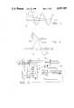
- FIG. 1is a waveform diagram illustrating the sinusoidal and exponential components of a sinusoidal waveform containing transient exponential noise.
- FIG. 2is a waveform diagram illustrating the technique in accordance with the invention of approximating the exponential component of the waveform of FIG. 1 as a linear function.
- FIG. 3is a schematic diagram of an electric power transmission system including a digital distance measuring relay incorporating the invention.
- FIG. 4is a flow diagram of a program for the digital distance measuring relay in the electric power transmission system of FIG. 3 implementing the invention.
- the first term of equation (1)represents the sinusoidal component and the second represents the exponential component, also referred to as the offset.
- FIG. 1An illustration of these components is shown in FIG. 1 where the resultant transient waveform 1 is resolved into the steady-state sinusoidal component 3 and the exponential component 5.
- the present inventionis directed to apparatus and a technique to reduce the effect of the exponential term using digital sampling of the waveform.
- the inventionassumes that the waveform is digitized and input to a microprocessor. It is further assumed that the sampling is uniform and asynchronous with respect to the waveform.
- the key to the inventionis to approximate the exponential component of the transient as a linear equation in any given cycle of fault data, as illustrated in FIG. 2 where 9 represents the sinusoidal term and 11 represents the straight line approximation of the exponential term.
- the well known equation for such a straight lineis:
- the constants ⁇ and ⁇ in this equationare the initial ordinate value and slope respectively of the line 11.
- the values of these constantsare determined from the digital samples of the waveform using a special algorithm. Once the linear approximation is found, it is subtracted from the input samples. The end result is a set of compensated samples with the offset removed.
- the waveformis sampled a number of times during each cycle at instants spaced by equal intervals of time, ⁇ .
- the waveformmay be sampled eight times per cycle as indicated in FIG. 2. While the initial sample is shown in FIG. 2 as being taken at the zero crossing of the sinusoidal term, this is for illustration only, and as mentioned, the sampling is asynchronous with the sinusoidal component. It is also assumed that the exponential term 11 is continuous over the period of the sine wave; this is, that it is present the entire time.
- equation (4)can be rewritten as:
- i(0)is the sinusoidal term and the remainder is the linear term and i(0) in the total current.
- equation (8)reduces to:
- equation (9)is designated i(04) and equation (10) is identified as i(15):
- Equation (12)is solved directly from the four digital samples i(0), i(1), i(4) and i(5).
- Equation (13)is also solved directly from four samples i(0), i(1), i(4) and i(5).
- ⁇the number of intervals, ⁇ , between corresponding samples in the two pairs of digital samples each of which are one-half cycle apart and n equals the number of samples per cycle.
- Equation 17determines ⁇ at the first sample.
- distance measuring relayscalculate the apparent impedance to a fault from the current and voltage, and compare it with a reach characteristic to determine if the fault is within the protection zone of the relay. These impedance calculations are obviously affected by transient exponential noise in the current and voltage waveforms. Clearly, the accuracy of the impedance calculations can be improved by a technique which eliminates this offset. It is imperative, however, that the offset be determined rapidly since in many instances the relay must make a trip decision quickly after fault inception. The present invention provides a rapid method of eliminating the offset with good accuracy.
- FIG. 3illustrates an electric power transmission system 13 with a distance measuring relay 15 incorporating the invention.
- the electric power transmission system 13includes a three-phase generator 17 feeding a three-phase transmission line 19.
- the transmission line 19can be isolated from the generator 17 by tripping of a circuit breaker 21 which is controlled by the distance measuring relay 15.
- Current transformers 23generate signals proportional to the three phase currents in the transmission line 19 for use by the distance measuring relay 15.
- potential transformers 25provide signals proportional to the line voltages.
- a multiplexer 27 within the relay 15serially applies the analog signals from the current and potential transformers to an analog to digital converter 29 which generates digital samples of the instantaneous values of the currents and voltages.
- the microprocessor 31processes the digital samples in accordance with the invention to reduce the effects of the transient exponential noise.
- a flow chart of a program which performs this taskis illustrated in FIG. 4.
- the sample number, Kis initialized at zero as indicated at 35.
- ⁇ and ⁇are calculated at 47 from equations (12) and (13) above using, in the case of a current, i(0), i(1), i(4) and i(5).
- the first six compensated values of the waveformare then calculated from ⁇ and ⁇ and the appropriate digital signals at 49.
- compensated values of more than one-half cycle of the waveformare available for the other functions of the digital relay.
- the microprocessor 15runs other programs using the compensated current and voltage waveforms to, among other things, detect fault inception, determine the apparent impedance to the fault, and make trip decisions.
- the trip signal 53operates the breaker 21 to disconnect the transmission line 19 from the generator 17.
Landscapes
- Physics & Mathematics (AREA)
- General Physics & Mathematics (AREA)
- Engineering & Computer Science (AREA)
- Power Engineering (AREA)
- Emergency Protection Circuit Devices (AREA)
- Supply And Distribution Of Alternating Current (AREA)
- Measurement Of Current Or Voltage (AREA)
Abstract
Description
i.sub.ex =α+βt Eq. (4)
i.sub.ex =α+βKΔ Eq. (5)
i(0)=i(0)+α+β (0·Δ) Eq. (6)
i(4)=i(4)+α+β(4Δ) Eq. (7)
i(0)+i(4)=iIo)(0)+i(4)+2α+4βΔ Eq. (8)
i(0)+i(4)=2α+4βΔ Eq. (9)
i(1)+i(5)=2α+6βΔ Eq. (10)
i(04)-i(15)=2α+4βΔ-2α-6βΔEq. (11)
α=i(04)/2 -2βΔ=3/2(i(0)-i(4))-i(1)-i(5) Eq. (13)
i(K)=i(K)-α-β(KΔ) Eq. (15)
Claims (6)
w(k)=w (k)-α-Kβ
Priority Applications (4)
| Application Number | Priority Date | Filing Date | Title |
|---|---|---|---|
| US07/207,354US4937769A (en) | 1988-06-15 | 1988-06-15 | Apparatus and method for reducing transient exponential noise in a sinusoidal signal |
| CA000601251ACA1312653C (en) | 1988-06-15 | 1989-05-31 | Apparatus and method for reducing transient exponential noise in a sinusoidal signal |
| KR1019890008170AKR900001082A (en) | 1988-06-15 | 1989-06-14 | Transient Exponential Noise Reduction Device and Method in Sine Wave Signal |
| JP1153576AJPH0241625A (en) | 1988-06-15 | 1989-06-15 | Method and apparatus for reducing transient exponential noise from a sinusoidal waveform |
Applications Claiming Priority (1)
| Application Number | Priority Date | Filing Date | Title |
|---|---|---|---|
| US07/207,354US4937769A (en) | 1988-06-15 | 1988-06-15 | Apparatus and method for reducing transient exponential noise in a sinusoidal signal |
Publications (1)
| Publication Number | Publication Date |
|---|---|
| US4937769Atrue US4937769A (en) | 1990-06-26 |
Family
ID=22770195
Family Applications (1)
| Application Number | Title | Priority Date | Filing Date |
|---|---|---|---|
| US07/207,354Expired - Fee RelatedUS4937769A (en) | 1988-06-15 | 1988-06-15 | Apparatus and method for reducing transient exponential noise in a sinusoidal signal |
Country Status (4)
| Country | Link |
|---|---|
| US (1) | US4937769A (en) |
| JP (1) | JPH0241625A (en) |
| KR (1) | KR900001082A (en) |
| CA (1) | CA1312653C (en) |
Cited By (21)
| Publication number | Priority date | Publication date | Assignee | Title |
|---|---|---|---|---|
| US5311446A (en)* | 1988-08-17 | 1994-05-10 | Active Noise And Vibration Technologies, Inc. | Signal processing system for sensing a periodic signal in the presence of another interfering signal |
| US5453903A (en)* | 1993-08-18 | 1995-09-26 | Abb Power T&D Company, Inc. | Sub-cycle digital distance relay |
| US5751532A (en)* | 1996-02-28 | 1998-05-12 | Basler Electric Company | Intergrating reset overcurrent relay |
| US20030191603A1 (en)* | 2002-02-14 | 2003-10-09 | Simon Raab | Portable coordinate measurement machine with integrated line laser scanner |
| US20040111908A1 (en)* | 2002-02-14 | 2004-06-17 | Simon Raab | Method for improving measurement accuracy of a protable coordinate measurement machine |
| US20050016008A1 (en)* | 2002-02-14 | 2005-01-27 | Simon Raab | Method for providing sensory feedback to the operator of a portable measurement machine |
| US20060016086A1 (en)* | 2002-02-14 | 2006-01-26 | Simon Raab | Portable coordinate measurement machine |
| US20060129349A1 (en)* | 2002-02-14 | 2006-06-15 | Simon Raab | Portable coordinate measurement machine with integrated line laser scanner |
| US20070294045A1 (en)* | 2002-02-14 | 2007-12-20 | Faro Technologies, Inc. | Portable coordinate measurement machine with integrated line laser scanner |
| US7532956B1 (en)* | 2004-08-24 | 2009-05-12 | Pelaez Jr Pedro | Distributed power and protection system |
| US7881896B2 (en) | 2002-02-14 | 2011-02-01 | Faro Technologies, Inc. | Portable coordinate measurement machine with integrated line laser scanner |
| US9182429B2 (en) | 2012-01-04 | 2015-11-10 | Sentient Energy, Inc. | Distribution line clamp force using DC bias on coil |
| US9229036B2 (en) | 2012-01-03 | 2016-01-05 | Sentient Energy, Inc. | Energy harvest split core design elements for ease of installation, high performance, and long term reliability |
| US9954354B2 (en) | 2015-01-06 | 2018-04-24 | Sentient Energy, Inc. | Methods and apparatus for mitigation of damage of power line assets from traveling electrical arcs |
| US9984818B2 (en) | 2015-12-04 | 2018-05-29 | Sentient Energy, Inc. | Current harvesting transformer with protection from high currents |
| US10634733B2 (en) | 2016-11-18 | 2020-04-28 | Sentient Energy, Inc. | Overhead power line sensor |
| US11041915B2 (en) | 2018-09-18 | 2021-06-22 | Sentient Technology Holdings, LLC | Disturbance detecting current sensor |
| US11125832B2 (en) | 2018-12-13 | 2021-09-21 | Sentient Technology Holdings, LLC | Multi-phase simulation environment |
| US11476674B2 (en) | 2018-09-18 | 2022-10-18 | Sentient Technology Holdings, LLC | Systems and methods to maximize power from multiple power line energy harvesting devices |
| US11609590B2 (en) | 2019-02-04 | 2023-03-21 | Sentient Technology Holdings, LLC | Power supply for electric utility underground equipment |
| US12050241B2 (en) | 2018-10-15 | 2024-07-30 | Sentient Technology Holdings, Llc. | Power line sensors with automatic phase identification |
Citations (9)
| Publication number | Priority date | Publication date | Assignee | Title |
|---|---|---|---|---|
| US4322641A (en)* | 1979-12-11 | 1982-03-30 | Packburn Electronics | Noise reduction system |
| US4455612A (en)* | 1982-01-27 | 1984-06-19 | Iowa State University Research Foundation, Inc. | Recursive estimation in digital distance relaying system |
| US4577279A (en)* | 1983-05-31 | 1986-03-18 | Westinghouse Electric Corp. | Method and apparatus for providing offset compensation |
| US4587620A (en)* | 1981-05-09 | 1986-05-06 | Nippon Gakki Seizo Kabushiki Kaisha | Noise elimination device |
| US4646254A (en)* | 1984-10-09 | 1987-02-24 | Gte Government Systems Corporation | Noise threshold estimating method for multichannel signal processing |
| US4684989A (en)* | 1986-02-07 | 1987-08-04 | Rca Corporation | Signal background noise detector |
| US4694414A (en)* | 1984-12-19 | 1987-09-15 | Rca Corporation | Digital delay interpolation filter with amplitude and phase compensation |
| US4727504A (en)* | 1984-07-05 | 1988-02-23 | The Charles Stark Draper Laboratory, Inc. | Interference canceller and signal quantizer |
| US4795983A (en)* | 1988-03-07 | 1989-01-03 | Westinghouse Electric Corp. | Method and apparatus for identifying a faulted phase |
- 1988
- 1988-06-15USUS07/207,354patent/US4937769A/ennot_activeExpired - Fee Related
- 1989
- 1989-05-31CACA000601251Apatent/CA1312653C/ennot_activeExpired - Fee Related
- 1989-06-14KRKR1019890008170Apatent/KR900001082A/ennot_activeCeased
- 1989-06-15JPJP1153576Apatent/JPH0241625A/enactivePending
Patent Citations (9)
| Publication number | Priority date | Publication date | Assignee | Title |
|---|---|---|---|---|
| US4322641A (en)* | 1979-12-11 | 1982-03-30 | Packburn Electronics | Noise reduction system |
| US4587620A (en)* | 1981-05-09 | 1986-05-06 | Nippon Gakki Seizo Kabushiki Kaisha | Noise elimination device |
| US4455612A (en)* | 1982-01-27 | 1984-06-19 | Iowa State University Research Foundation, Inc. | Recursive estimation in digital distance relaying system |
| US4577279A (en)* | 1983-05-31 | 1986-03-18 | Westinghouse Electric Corp. | Method and apparatus for providing offset compensation |
| US4727504A (en)* | 1984-07-05 | 1988-02-23 | The Charles Stark Draper Laboratory, Inc. | Interference canceller and signal quantizer |
| US4646254A (en)* | 1984-10-09 | 1987-02-24 | Gte Government Systems Corporation | Noise threshold estimating method for multichannel signal processing |
| US4694414A (en)* | 1984-12-19 | 1987-09-15 | Rca Corporation | Digital delay interpolation filter with amplitude and phase compensation |
| US4684989A (en)* | 1986-02-07 | 1987-08-04 | Rca Corporation | Signal background noise detector |
| US4795983A (en)* | 1988-03-07 | 1989-01-03 | Westinghouse Electric Corp. | Method and apparatus for identifying a faulted phase |
Non-Patent Citations (2)
| Title |
|---|
| Alternating Current Circuits, Russell M. Kerchner, M.S. et al., Second Edition, New York, Chapter 16, John Wiley & Sons, Inc.* |
| Unified Protection, Monitoring, and Control of Overhead Transmission Line Achieves Performance and Economy, Edmund O. Schweitzer, III Phd, Schweitzer Engineering Laboratories, Pullman, Wash.* |
Cited By (54)
| Publication number | Priority date | Publication date | Assignee | Title |
|---|---|---|---|---|
| US5311446A (en)* | 1988-08-17 | 1994-05-10 | Active Noise And Vibration Technologies, Inc. | Signal processing system for sensing a periodic signal in the presence of another interfering signal |
| US5453903A (en)* | 1993-08-18 | 1995-09-26 | Abb Power T&D Company, Inc. | Sub-cycle digital distance relay |
| US5751532A (en)* | 1996-02-28 | 1998-05-12 | Basler Electric Company | Intergrating reset overcurrent relay |
| US7519493B2 (en) | 2002-02-14 | 2009-04-14 | Faro Technologies, Inc. | Portable coordinate measurement machine with integrated line laser scanner |
| US7174651B2 (en) | 2002-02-14 | 2007-02-13 | Faro Technologies, Inc. | Portable coordinate measurement machine |
| US20050016008A1 (en)* | 2002-02-14 | 2005-01-27 | Simon Raab | Method for providing sensory feedback to the operator of a portable measurement machine |
| US20050028393A1 (en)* | 2002-02-14 | 2005-02-10 | Simon Raab | Method for improving measurement accuracy of a portable coordinate measurement machine |
| US20050115092A1 (en)* | 2002-02-14 | 2005-06-02 | Simon Raab | Portable coordinate measurement machine with improved handle assembly |
| US20050144799A1 (en)* | 2002-02-14 | 2005-07-07 | Simon Raab | Portable coordinate measurement machine |
| US6935036B2 (en) | 2002-02-14 | 2005-08-30 | Faro Technologies, Inc. | Portable coordinate measurement machine |
| US20050188557A1 (en)* | 2002-02-14 | 2005-09-01 | Simon Raab | Apparatus for providing sensory feedback to the operator of a portable measurement machine |
| US20050222803A1 (en)* | 2002-02-14 | 2005-10-06 | Simon Raab | Portable coordinate measurement machine with integrated line laser scanner |
| US6965843B2 (en) | 2002-02-14 | 2005-11-15 | Faro Technologies, Inc. | Portable coordinate measurement machine with integrated line laser scanner |
| US6988322B2 (en) | 2002-02-14 | 2006-01-24 | Faro Technologies, Inc. | Apparatus for providing sensory feedback to the operator of a portable measurement machine |
| US20060016086A1 (en)* | 2002-02-14 | 2006-01-26 | Simon Raab | Portable coordinate measurement machine |
| US20060053647A1 (en)* | 2002-02-14 | 2006-03-16 | Simon Raab | Method for improving measurement accuracy of a portable coordinate measurement machine |
| US7017275B2 (en) | 2002-02-14 | 2006-03-28 | Faro Technologies, Inc. | Portable coordinate measurement machine with improved handle assembly |
| US7032321B2 (en) | 2002-02-14 | 2006-04-25 | Faro Technologies, Inc. | Portable coordinate measurement machine |
| US7050930B2 (en) | 2002-02-14 | 2006-05-23 | Faro Technologies, Inc. | Portable coordinate measurement machine with integrated line laser scanner |
| US20060129349A1 (en)* | 2002-02-14 | 2006-06-15 | Simon Raab | Portable coordinate measurement machine with integrated line laser scanner |
| US7069664B2 (en) | 2002-02-14 | 2006-07-04 | Faro Technologies, Inc. | Portable coordinate measurement machine |
| US7073271B2 (en) | 2002-02-14 | 2006-07-11 | Faro Technologies Inc. | Portable coordinate measurement machine |
| US7881896B2 (en) | 2002-02-14 | 2011-02-01 | Faro Technologies, Inc. | Portable coordinate measurement machine with integrated line laser scanner |
| US7246030B2 (en) | 2002-02-14 | 2007-07-17 | Faro Technologies, Inc. | Portable coordinate measurement machine with integrated line laser scanner |
| US7269910B2 (en) | 2002-02-14 | 2007-09-18 | Faro Technologies, Inc. | Method for improving measurement accuracy of a portable coordinate measurement machine |
| US20070294045A1 (en)* | 2002-02-14 | 2007-12-20 | Faro Technologies, Inc. | Portable coordinate measurement machine with integrated line laser scanner |
| US20030191603A1 (en)* | 2002-02-14 | 2003-10-09 | Simon Raab | Portable coordinate measurement machine with integrated line laser scanner |
| US20040111908A1 (en)* | 2002-02-14 | 2004-06-17 | Simon Raab | Method for improving measurement accuracy of a protable coordinate measurement machine |
| US8572858B2 (en) | 2002-02-14 | 2013-11-05 | Faro Technologies, Inc. | Portable coordinate measurement machine having a removable external sensor |
| USRE42055E1 (en) | 2002-02-14 | 2011-01-25 | Faro Technologies, Inc. | Method for improving measurement accuracy of a portable coordinate measurement machine |
| US8595948B2 (en) | 2002-02-14 | 2013-12-03 | Faro Technologies, Inc. | Portable coordinate measurement machine with a rotatable handle |
| US8607467B2 (en) | 2002-02-14 | 2013-12-17 | Faro Technologies, Inc. | Portable coordinate measurement machine |
| US8931182B2 (en) | 2002-02-14 | 2015-01-13 | Faro Technologies, Inc. | Portable coordinate measurement machine having a handle that includes electronics |
| US9410787B2 (en) | 2002-02-14 | 2016-08-09 | Faro Technologies, Inc. | Portable coordinate measurement machine having a bearing assembly with an optical encoder |
| US9513100B2 (en) | 2002-02-14 | 2016-12-06 | Faro Technologies, Inc. | Portable coordinate measurement machine having a handle that includes electronics |
| US10168134B2 (en) | 2002-02-14 | 2019-01-01 | Faro Technologies, Inc. | Portable coordinate measurement machine having a handle that includes electronics |
| US7532956B1 (en)* | 2004-08-24 | 2009-05-12 | Pelaez Jr Pedro | Distributed power and protection system |
| US9229036B2 (en) | 2012-01-03 | 2016-01-05 | Sentient Energy, Inc. | Energy harvest split core design elements for ease of installation, high performance, and long term reliability |
| US11789042B2 (en) | 2012-01-03 | 2023-10-17 | Sentient Technology Holdings, LLC | Energy harvest split core design elements for ease of installation, high performance, and long term reliability |
| US10901008B2 (en) | 2012-01-03 | 2021-01-26 | Sentient Technology Holdings, LLC | Energy harvest split core design elements for ease of installation, high performance, and long term reliability |
| US9182429B2 (en) | 2012-01-04 | 2015-11-10 | Sentient Energy, Inc. | Distribution line clamp force using DC bias on coil |
| US9448257B2 (en) | 2012-01-04 | 2016-09-20 | Sentient Energy, Inc. | Distribution line clamp force using DC bias on coil |
| US9954354B2 (en) | 2015-01-06 | 2018-04-24 | Sentient Energy, Inc. | Methods and apparatus for mitigation of damage of power line assets from traveling electrical arcs |
| US9984818B2 (en) | 2015-12-04 | 2018-05-29 | Sentient Energy, Inc. | Current harvesting transformer with protection from high currents |
| US11442114B2 (en) | 2016-11-18 | 2022-09-13 | Sentient Technology Holdings, LLC | Overhead power line sensor |
| US10634733B2 (en) | 2016-11-18 | 2020-04-28 | Sentient Energy, Inc. | Overhead power line sensor |
| US11041915B2 (en) | 2018-09-18 | 2021-06-22 | Sentient Technology Holdings, LLC | Disturbance detecting current sensor |
| US11476674B2 (en) | 2018-09-18 | 2022-10-18 | Sentient Technology Holdings, LLC | Systems and methods to maximize power from multiple power line energy harvesting devices |
| US12050241B2 (en) | 2018-10-15 | 2024-07-30 | Sentient Technology Holdings, Llc. | Power line sensors with automatic phase identification |
| US11125832B2 (en) | 2018-12-13 | 2021-09-21 | Sentient Technology Holdings, LLC | Multi-phase simulation environment |
| US11549997B2 (en) | 2018-12-13 | 2023-01-10 | Sentient Technology Holdings, LLC | Multi-phase simulation environment |
| US11835593B2 (en) | 2018-12-13 | 2023-12-05 | Sentient Technology Holdings, LLC | Multi-phase simulation environment |
| US11609590B2 (en) | 2019-02-04 | 2023-03-21 | Sentient Technology Holdings, LLC | Power supply for electric utility underground equipment |
| US11947374B2 (en) | 2019-02-04 | 2024-04-02 | Sentient Technology Holdings, LLC | Power supply for electric utility underground equipment |
Also Published As
| Publication number | Publication date |
|---|---|
| JPH0241625A (en) | 1990-02-09 |
| KR900001082A (en) | 1990-01-31 |
| CA1312653C (en) | 1993-01-12 |
Similar Documents
| Publication | Publication Date | Title |
|---|---|---|
| US4937769A (en) | Apparatus and method for reducing transient exponential noise in a sinusoidal signal | |
| US3984737A (en) | Protective relaying system | |
| CA1063174A (en) | Method and apparatus for locating a fault on a line | |
| US4251766A (en) | Method and apparatus for determining the direction of a fault on a power transmission line | |
| US5060166A (en) | Method and apparatus for rapidly analyzing AC waveforms containing DC offsets | |
| US4261038A (en) | Protection of electrical power supply systems | |
| RU2172011C2 (en) | Digital comparator | |
| EP0316204A2 (en) | Protective relay | |
| US4577279A (en) | Method and apparatus for providing offset compensation | |
| KR910002055B1 (en) | Digital protection relay | |
| US4333151A (en) | Method for protecting an electric power system and digital protective system | |
| EP0026620A1 (en) | Method and apparatus for identifying faults in electric power transmission systems | |
| Hwang et al. | Fault current phasor estimation below one cycle using Fourier analysis of decaying DC component | |
| US4943766A (en) | Electric quantity detecting method | |
| EP0581015A2 (en) | Method for determining fault currents on transmission lines and a fault current filter for carrying out the method | |
| US6173216B1 (en) | Protective relay with improved, sub-window cosine filter | |
| Lian et al. | An overview of digital fault location algorithms for power transmission lines using transient waveforms | |
| CA1301350C (en) | Obtaining a selected frequency component in rectangular coordinates from a set of electrical waveforms | |
| US4785249A (en) | Method for measuring distance in digital distance relays | |
| Eissa | A novel wavelet approach to busbar protection during CT saturation and ratio-mismatch | |
| Soldatov et al. | Informational fundamentals of the multiparameter differential protection of busbar generators against single line-to-ground faults | |
| EP0367563B1 (en) | Detector of quantity of electricity | |
| US5777835A (en) | Third phase reconstruction from a two current transformer sensor with three-phase true RMS and phase loss determination capabilities | |
| US6154687A (en) | Modified cosine filters | |
| JPH01170865A (en) | Detecting device for grounding failure point of electric distribution line |
Legal Events
| Date | Code | Title | Description |
|---|---|---|---|
| AS | Assignment | Owner name:WESTINGHOUSE ELECTRIC CORPORATION, WESTINGHOUSE BU Free format text:ASSIGNMENT OF ASSIGNORS INTEREST.;ASSIGNOR:VERBANETS, WILLIAM R.;REEL/FRAME:004931/0106 Effective date:19880725 Owner name:WESTINGHOUSE ELECTRIC CORPORATION,PENNSYLVANIA Free format text:ASSIGNMENT OF ASSIGNORS INTEREST;ASSIGNOR:VERBANETS, WILLIAM R.;REEL/FRAME:004931/0106 Effective date:19880725 | |
| AS | Assignment | Owner name:ABB POWER T&D COMPANY, INC., A DE CORP., PENNSYLV Free format text:ASSIGNMENT OF ASSIGNORS INTEREST.;ASSIGNOR:WESTINGHOUSE ELECTRIC CORPORATION, A CORP. OF PA.;REEL/FRAME:005368/0692 Effective date:19891229 | |
| FEPP | Fee payment procedure | Free format text:PAYOR NUMBER ASSIGNED (ORIGINAL EVENT CODE: ASPN); ENTITY STATUS OF PATENT OWNER: LARGE ENTITY | |
| FPAY | Fee payment | Year of fee payment:4 | |
| REMI | Maintenance fee reminder mailed | ||
| LAPS | Lapse for failure to pay maintenance fees | ||
| FP | Lapsed due to failure to pay maintenance fee | Effective date:19980701 | |
| STCH | Information on status: patent discontinuation | Free format text:PATENT EXPIRED DUE TO NONPAYMENT OF MAINTENANCE FEES UNDER 37 CFR 1.362 |