US4936305A - Shielded magnetic assembly for use with a hearing aid - Google Patents
Shielded magnetic assembly for use with a hearing aidDownload PDFInfo
- Publication number
- US4936305A US4936305AUS07/221,932US22193288AUS4936305AUS 4936305 AUS4936305 AUS 4936305AUS 22193288 AUS22193288 AUS 22193288AUS 4936305 AUS4936305 AUS 4936305A
- Authority
- US
- United States
- Prior art keywords
- magnet
- face
- shielding cap
- side face
- magnet means
- Prior art date
- Legal status (The legal status is an assumption and is not a legal conclusion. Google has not performed a legal analysis and makes no representation as to the accuracy of the status listed.)
- Expired - Lifetime
Links
Images


Classifications
- H—ELECTRICITY
- H04—ELECTRIC COMMUNICATION TECHNIQUE
- H04R—LOUDSPEAKERS, MICROPHONES, GRAMOPHONE PICK-UPS OR LIKE ACOUSTIC ELECTROMECHANICAL TRANSDUCERS; DEAF-AID SETS; PUBLIC ADDRESS SYSTEMS
- H04R25/00—Deaf-aid sets, i.e. electro-acoustic or electro-mechanical hearing aids; Electric tinnitus maskers providing an auditory perception
- H04R25/60—Mounting or interconnection of hearing aid parts, e.g. inside tips, housings or to ossicles
- H04R25/604—Mounting or interconnection of hearing aid parts, e.g. inside tips, housings or to ossicles of acoustic or vibrational transducers
- H04R25/606—Mounting or interconnection of hearing aid parts, e.g. inside tips, housings or to ossicles of acoustic or vibrational transducers acting directly on the eardrum, the ossicles or the skull, e.g. mastoid, tooth, maxillary or mandibular bone, or mechanically stimulating the cochlea, e.g. at the oval window
Definitions
- the present inventionrelates to magnet structures and more particularly to magnet structures for use with magnetically coupled hearing aids.
- Conventional hearing aidsutilize detection, amplification and retransmission of the acoustic waves forming sound. Because of a number of well known problems with conventional hearing aids, magnetically coupled hearing aids were investigated.
- a magnet or magnetic materialis placed in the middle ear so that any movement of the magnet structure is perceived as sound by the wearer.
- the hearing aidincludes a coil used to develop a magnetic field which is coupled to the magnetic field produced by the magnetic material.
- the coil magnetic fieldis varied based on the received sound waves, with the coupling between the two fields causing the magnetic material to vibrate in sympathy. This motion of the magnetic material then vibrates the connected portion of the middle ear and sound is perceived by the wearer.
- the couplingcould be increased by increasing the strength of the magnetic field output by the hearing aid coil.
- One way to increase this fieldis to increase the current in the coil, thereby increasing the ampere-turns value. This increase is practical only within given limits because the increase in current directly affects battery life.
- Increasing the number of turnsis also possible, but again has practical limitations. Because of the limited volume that can be occupied by the coil, especially if the coil is located in the ear canal, the number of turns can only be increased by reducing the size of the wire forming the coil. However, as this wire size is reduced, its unit resistance, and therefore overall coil resistance, increases. Because the amplifier driving the coil is customarily a voltage source, it is sensitive to this output load and the current provided to the coil can reduce as the resistance increases. Therefore, there are only limited gains to be obtained by changing the coil current or number of turns. Gains must be developed in a manner other than simply increasing ampere-turns value.
- the coilcould be placed closer to the magnetic material, but given the size of the hearing aid components and the vulnerability of the middle ear, certain effective minimum spacings are necessary, particularly if the extended surgery that may be necessary for very close implantation is not desirable or possible. Additionally, it is desirable that as much of the hearing aid as possible is easily removable, to limit surgical problems and to ease repair and replacement of the hearing aid and its battery. This removability, when coupled with the physical sizes of the hearing aid components, limits the attainable distance between the coil and magnetic material.
- a magnetic assembly according to the present inventionutilizes a magnetic material and a shielding cap.
- the shielding capis a highly permeable, low coercivity material which is located on at least the side of the magnetic material away from the air gap between the coil and the magnetic material.
- the shielding capconfines the energy stored in the magnetic material's magnetic field to the region or air gap between the coil and the magnetic material. This confining or focusing of the energy results in improved coupling between the two magnetic fields, with the concomitant increase in the hearing aid's efficiency.
- the shielding caphas the added benefit of reducing the interaction between the magnetic material and external magnetic fields.
- the magnetic materialis preferably disc-shaped, having a thickness less than the effective width or diameter.
- the magnetic materialis a high energy material such as samarium cobalt or neodymium-iron.
- the shielding capis shaped to mate with the magnetic material and cover at least one face, with the shielding cap preferably extending over the edges of the disc, so that over one-half, effectively one magnetic pole, of the magnetic material is surrounded by the shielding cap.
- the shielding capis formed of a high permeability, low coercivity material, such as permalloy or mumetal.
- the magnetic material and the shielding cappreferably have a uniform thickness, but may have a thickness varying with the distance from the longitudinal axis of the assembly.
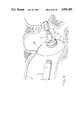
- FIG. 1is a schematic view of a magnet according to the prior art and its representative flux lines
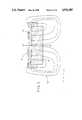
- FIG. 2is a schematic view of a shielded magnetic assembly of the present invention along with a magnetic hearing aid coil and representations of their respective flux lines;
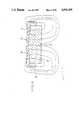
- FIGS. 3, 5 and 6are schematic views of shielded magnetic assemblies according to the present invention and representations of their respective flux lines;
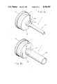
- FIG. 4is an exploded, perspective view of the shielded magnetic assembly of FIGS. 2 and 3;
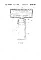
- FIGS. 7 and 8are side views in partial cross-section of prostheses including a shielded magnetic assembly according to the present invention.
- FIGS. 7A and 8Aare perspective views of the prostheses of FIGS. 7 and 8, respectively;
- FIG. 9is a representation showing the ear canal, the middle ear, a coil and the prosthesis of FIG. 8;
- FIG. 10is a cross-sectional view of a coated, shielded magnetic assembly according to the present invention.
- An uncapped magnet U(FIG. 1) has a magnetic field F u which is symmetric or uniform about the faces 10 and 12 of the magnet U when the magnetic poles are aligned with the faces 10 and 12 of the magnet U.
- the representations of the magnets and their respective magnetic fields in the figuresare shown as two dimensional for simplicity and ease of explanation, but it is understood that the shapes of the magnets and fields are three dimensional, generally developed by revolving the illustrated portions about an axis for cylindrical embodiments.
- the energy stored in this uniform magnetic field F ucan be considered as being stored in the volume enclosed by the representative lines of flux. As a result, the energy density is high near the field source, the magnet U, and diminishes with the distance from the field source.
- a coil CIn a magnetically coupled hearing aid, a coil C (FIG. 2) produces a magnetic field F c .
- a microphonereceives the acoustic sound waves and converts them into an electrical signal. This signal is filtered if desired and amplified. The amplified signal is applied to the coil C which produces the magnetic field F c .
- the magnetic field F cvaries with the frequency and amplitude of the sound waves received by the hearing aid, as explained in U.S. Pat. application, Ser. No. 837,708, filed Mar. 7, 1986 issued as U.S. Pat. No. 4,800,884 on Jan.
- the coil field F cinteracts with the magnetic field F m produced by a magnet M.
- the magnetic field F mis a constant field because the magnet M has a fixed strength.
- the coupling or interaction between the coil field F c and the magnet field F mcauses the magnet M to vibrate at the frequency of the coil field F c .
- This couplingis shown in FIG. 2 where the fields F c and F m are of opposite or attractive polarity, so that the flux lines appear to merge, because the magnetic circuit is being formed between the magnet M and the coil C.
- the fields F c and F mare of like or repulsive polarity in the air gap, the respective flux lines are closed loops, indicating that two magnetic circuits are present.
- the amplitude of the vibration of the magnet Mvaries depending on the quality of the coupling of the two fields F c and F m and the mass of the magnet M.
- the quality of the couplingis based on the air gap distance d and the strength or interacting energy of the two fields F c and F m . If the air gap distance d is reduced or the strength or interacting energy of one of the fields F c or F m is increased, the coupling improves and the vibrational amplitude of the magnet M increases. Because a given amplitude of magnet M movement is necessary to produce a perceived sound level, improving the coupling increases the perceived sound level. If the energy consumption of the hearing aid is not increased in improving the coupling, the efficiency of the hearing aid is increased and battery life is extended.
- the magnet Mhas one face 14 substantially facing the coil C and one face 16 substantially facing away from the coil C with the magnetic poles generally aligned with these faces 14 and 16.
- the axis 20 of the magnet Mis generally aligned with the axis 18 of the coil C in the embodiment illustrated in FIG. 2.
- the magnet field F m or its coupling with the coil field F cmust be improved.
- the magnetic field F u of the uncoated magnet Uis uniform about the two faces 10 and 12 of the magnet U.
- an appreciable portion of the energy stored in the field F uis not utilized in the coupling of the uncoated magnet U and the coil C. It is desirable that more of the energy be focused into the air gap A, so that the useful energy developed in the magnet field F m is increased.
- the shielded magnet assembly S(FIG. 3), which is similar to the magnet M of FIG. 2, with the letter S generally referring to a shielded magnet assembly according to the present invention and the numeral referring to a particular embodiment, focuses or directs more of the energy contained in its magnetic field F s .sbsb.1 into the air gap A than an uncoated magnet U of equivalent strength.
- the shielded assembly S 1is comprised of two pieces, a magnet 22 and a shielding cap 24.
- the magnet 22is preferably cylindrical (FIG. 4) and relatively thin, so that the magnet 22 has a radius r and a thickness t, with the thickness t preferably being less than twice the radius r.
- the magnet 22can have other shapes as desired, such as hexagonal or square, or other shapes as are apparent to those skilled in the art.
- the magnet 22is preferably formed of high energy magnetic materials, such as samarium cobalt, neodymium-iron or other similar materials, to reduce the size and mass of the magnet 22 needed to develop a given magnetic field F s .sbsb.1.
- the magnet 22is formed using conventional techniques.
- the shielding cap 24is shaped to mate with the magnet 22.
- the cap 24contains a recess 26 into which the magnet 22 fits snugly.
- Preferably the air gaps between the cap 24 and the magnet 22are kept to a minimum to increase the magnet field focusing property of the assembly S .
- the recess 26has a depth of approximately one-half the magnet thickness t so that effectively one pole of the magnet 22 is shielded, limiting the magnetic flux which can form a circuit without traversing the shielding cap 24.
- the shielding cap 24is preferably formed of a high permeability and low coercivity material, for example, permalloy or mumetal.
- the materialcan be annealed to increase the relative permeability of the material, but satisfactory results are had when the material is not annealed.
- the shielding cap 24is preferably machined from either cylindrical stock or from stock cast to approximate the finished shape to keep any differences between the shape of the recess 26 and the magnet 22 to a minimum.
- a series magnetic circuitis formed from one face or pole 28 of the magnet 22 to the other face 30, with the circuit elements being the shielding cap 24 and the air in the volume where the circuit is completed. In a series magnetic circuit the energy is primarily stored in the least permeable portions of the circuit.
- the energy in the shielded field F s .sbsb.1is contained primarily in the air gap A, resulting in improved coupling between the coil field F c and the shielded field F s .sbsb.1 over the unshielded field F u because of the increased energy in the air gap A for the magnetic field F s .sbsb.1, which improves the magnetic coupling.
- the shielded assembly S 1has a greater effective output level, particularly at the higher frequencies between 5000 and 8000 Hz, than an unshielded magnet U given equal magnet sizes and magnet energies.
- a fourth testwas performed with an uncapped magnet U of the same material and diameter, but having an increased thickness to approximately 0.05 inches, so that the magnet U weighed approximately 57 mg, the same as the shielded assembly S 1 , under test.
- the shielded assembly S 1does provide improved output characteristics at higher frequencies when compared with an uncapped magnet U having the same weight as the shielded assembly S 1 .
- the larger unshielded magnet Uis vulnerable to interference developed by the presence of external magnetic fields.
- the external fieldscan be produced by transformers used in electronic equipment. The external fields couple with the magnetic field of the magnet and cause a low frequency interference to be heard by the wearer.
- the focusing of the magnetic field F s .sbsb.1 in the air gap A and the resultant decrease in the field F s .sbsb.1 in other positionsreduces the interference caused by external magnetic fields. Less energy exists in positions not coupled with the coil C. As a result, there is less energy to easily couple with external fields produced by transformers and the like, and any external coupling occurring in the air gap region must overcome the signal or field of the coil C. Therefore the shielded assembly S 1 has a reduced amount of external field pickup. Tests were performed using the unshielded magnet U and the shielded magnet assembly S 1 of Test 4. When this assembly S 1 was placed near a power transformer, a vibration equivalent to a sound pressure level of 87.4 decibels was obtained. The uncapped magnet U in the same location produced a vibration equivalent to a sound pressure level of 109.9 decibels, or an increase of 22.5 decibels over the shielded assembly S 1 .
- the shielding cap 24covers the edge of magnet 22 so that effectively one entire pole of the magnet 22 is covered and no paths exist which do not include the shielding cap 24 in the magnetic circuit. This improves the effectiveness of the magnetic field focus as compared to a second shielded assembly S 2 (FIG. 5), where a shielding disc 32 is provided instead of a shielding cap 24.
- the shielding disc 32is substantially the same size and shape as the back face 28 of the magnet 22 and does not overlap the edges of the magnet 22.
- the disc 32does not bend or focus the magnetic field F s .sbsb.2 into the air gap A as much as the shielding cap 24 and the coupling between the magnetic fields of the disc shielded assembly S 2 and the coil C is less than the coupling between the magnetic fields of the capped magnet assembly S 1 and the coil C.
- the coupling of the fields F s .sbsb.2 and F cis still an improvement over an unshielded magnet U.
- the disc 32is preferably formed of similar material as the shielding cap 24.
- a magnetic assembly S 3is provided having a magnet 40 and a shielding cap 42 with varying thicknesses.
- the magnet 40is generally cylindrical, having a plane face 44 on the air gap A side and a conical face 46 away from the air gap A.
- the tapered shielding cap 42is correspondingly thin at the central axis, and thickens to the edge of the magnet 40.
- the tapered cap 42preferably has a lip 48 which covers portions of the edge of the magnet 40 to allow improved magnetic field focusing.
- the magnet 40is preferably formed of a high energy material and the tapered cap 42 is formed of a high permeability, low coercivity material.
- the shielded magnet assembly Scan be placed in the ear in a number of ways.
- the magnet assembly Scan be placed in a total ossicular replacement prosthesis T (FIGS. 7 and 7A) or a partial ossicular replacement prosthesis P (FIGS. 8 and 8A) according to the disclosure of U.S. Pat. application, Ser. No. 050,909, filed May 15, 1987, issued as U.S. Pat. No. 4,817,607 on Apr. 4, 1989, and owned by the same entity that owns the subject application, the disclosure of which is hereby incorporated by reference as though fully contained herein.
- the shielded magnet assembly Sis placed inside a biocompatible container 60.
- the container 60is preferably formed of titanium, but can be formed of any suitable biocompatible material which has a relative magnetic permeability of approximately one and can seal the shielded magnet assembly S from the body.
- the container 60includes a generally cylindrical mounting post 62 which is preferably hollow and has an outer surface including a tapered portion 64.
- a shaft 66is inserted into the hollow portion of the mounting post 62.
- a hollow shaft 68is used, with the hollow shaft 68 being installed over the mounting post 62, so that the tapered portion 64 grips the inside of the shaft 68.
- the container 60preferably has a porous biocompatible coating 70 over the portion of the container 60 which contacts the tympanic membrane.
- This porous coating 70can be an appropriate polymer or hydroxyapatite, to allow positive connection to the tympanic membrane over time as tissue ingrowth occurs.
- the partial prosthesis Pis shown implanted in the middle ear in FIG. 9.
- the malleus and the incushave been removed as appropriate when using a partial ossicular replacement prosthesis.
- the partial prosthesis Pcontacts the tympanic membrane 92 and the stapes 90 to provide conduction of the received acoustic waves to the inner ear 94.
- the coil C of the hearing aidis shown placed in the ear canal 94, so that the magnetic fields of the coil C and the shielded assembly S in the partial prosthesis P can interact and provide movement to the stapes 90 to simulate sound. Therefore the partial prosthesis P allows both acoustic and magnetic energy to be transferred to the inner ear to be perceived as sound.
- the shielded assembly Scan be directly implanted in an appropriate location in the middle ear.
- Such an assembly Smay be directly biocompatibly coated 50 (FIG. 10) or may be placed in a biocompatible container (not shown) which has a further biocompatible coating.
- the magnet 20 and shielding cap 24are coated by the biocompatible coating 50 to prevent corrosion or rejection when implanted and preferably to allow tissue ingrowth for positive attachment.
- the biocompatible coating 50may be any satisfactory material, such as hydroxyapatite, biocompatible polymers, and other materials known to those skilled in the art.
Landscapes
- Health & Medical Sciences (AREA)
- General Health & Medical Sciences (AREA)
- Otolaryngology (AREA)
- Neurosurgery (AREA)
- Physics & Mathematics (AREA)
- Engineering & Computer Science (AREA)
- Acoustics & Sound (AREA)
- Signal Processing (AREA)
- Prostheses (AREA)
- Shielding Devices Or Components To Electric Or Magnetic Fields (AREA)
- Audible-Bandwidth Dynamoelectric Transducers Other Than Pickups (AREA)
- Soft Magnetic Materials (AREA)
Abstract
Description
______________________________________ Improvement Test Uncapped Shielded with Frequency Magnet U Assembly S.sub.1 Shielding (Hz) (dBSPL) (dBSPL) (dBSPL) ______________________________________TEST 1 Effective Sound Pressure Levels of Shielded and Unshielded Magnets Coil Current of 750 μA 125 102.1 110.0 8.0 250 103.5 113.2 9.7 500 106.2 114.4 8.2 750 103.4 116.4 11.0 1000 103.0 113.5 10.5 1500 103.2 116.2 11.0 2000 106.2 119.0 12.8 3000 109.5 121.0 11.5 4000 108.4 115.5 7.1 5000 102.1 112.4 10.3 6000 95.5 103.7 8.2 7000 93.2 108.6 15.6 8000 95.5 103.5 8.0 TEST 2 Effective Sound Pressure Levels of Shielded and Unshielded Magnets Coil Current of 750 μA 125 98.3 106.4 8.5 250 100.8 106.4 5.6 500 100.5 105.9 5.4 750 99.6 108.0 8.4 1000 98.6 108.0 9.4 1500 100.7 106.4 5.7 2000 99.8 104.4 4.6 3000 106.5 106.7 0.2 4000 98.2 102.8 4.6 5000 96.1 87.2 -8.9 6000 83.1 99.7 16.6 7000 82.7 93.7 11.0 8000 83.1 86.2 3.1 TEST 3 Effective Sound Pressure Levels of Shielded and Unshielded Magnets Coil Current of 500 μA 125 96.5 103.8 7.3 250 98.0 102.3 4.7 500 97.5 97.5 0.0 750 97.6 98.1 0.5 1000 96.8 99.6 2.8 1500 97.4 95.5 -1.9 2000 97.0 99.9 2.9 3000 100.9 101.1 0.2 4000 96.4 99.9 3.5 5000 92.7 98.4 5.7 6000 82.0 97.2 15.2 7000 80.0 91.5 11.5 8000 81.5 85.4 3.9 ______________________________________
______________________________________ TEST 4 Effective Sound Pressure Levels of Shielded and Unshielded Magnets Coil Current of 750 μA 57 mg Improvement Test Uncapped Shielded with Frequency Magnet U Assembly S.sub.1 Shielding (Hz) (dBSPL) (dBSPL) (dBSPL) ______________________________________ 125 97.4 99.1 1.7 250 97.7 96.3 -1.4 500 95.2 96.5 1.3 750 94.8 95.2 0.4 1000 94.7 94.6 -0.1 1500 95.8 94.4 -1.4 2000 93.0 94.3 1.3 3000 86.6 88.7 2.1 4000 79.7 86.4 6.7 5000 65.8 77.6 11.8 6000 65.0 67.4 2.4 7000 54.9 60.4 5.5 8000 63.1 62.3 -0.8 ______________________________________
Claims (16)
Priority Applications (7)
| Application Number | Priority Date | Filing Date | Title |
|---|---|---|---|
| US07/221,932US4936305A (en) | 1988-07-20 | 1988-07-20 | Shielded magnetic assembly for use with a hearing aid |
| CA000605923ACA1311424C (en) | 1988-07-20 | 1989-07-18 | Shielded magnetic assembly for use with a hearing aid |
| AT89307282TATE111290T1 (en) | 1988-07-20 | 1989-07-19 | SHIELDED MAGNETIC ARRANGEMENT FOR USE IN A HEARING AID. |
| JP1184865AJPH02119400A (en) | 1988-07-20 | 1989-07-19 | Shield-magnet-assembly for hearing aid |
| AU38256/89AAU608200B2 (en) | 1988-07-20 | 1989-07-19 | Shielded magnetic assembly for use with a hearing aid |
| EP89307282AEP0352954B1 (en) | 1988-07-20 | 1989-07-19 | Shielded magnetic assembly for use with a hearing aid |
| DE68918020TDE68918020D1 (en) | 1988-07-20 | 1989-07-19 | Shielded magnetic assembly for use in a hearing aid. |
Applications Claiming Priority (1)
| Application Number | Priority Date | Filing Date | Title |
|---|---|---|---|
| US07/221,932US4936305A (en) | 1988-07-20 | 1988-07-20 | Shielded magnetic assembly for use with a hearing aid |
Publications (1)
| Publication Number | Publication Date |
|---|---|
| US4936305Atrue US4936305A (en) | 1990-06-26 |
Family
ID=22830025
Family Applications (1)
| Application Number | Title | Priority Date | Filing Date |
|---|---|---|---|
| US07/221,932Expired - LifetimeUS4936305A (en) | 1988-07-20 | 1988-07-20 | Shielded magnetic assembly for use with a hearing aid |
Country Status (7)
| Country | Link |
|---|---|
| US (1) | US4936305A (en) |
| EP (1) | EP0352954B1 (en) |
| JP (1) | JPH02119400A (en) |
| AT (1) | ATE111290T1 (en) |
| AU (1) | AU608200B2 (en) |
| CA (1) | CA1311424C (en) |
| DE (1) | DE68918020D1 (en) |
Cited By (63)
| Publication number | Priority date | Publication date | Assignee | Title |
|---|---|---|---|---|
| WO1992009181A1 (en)* | 1990-11-07 | 1992-05-29 | Resound Corporation | Contact transducer assembly for hearing devices |
| US5163957A (en)* | 1991-09-10 | 1992-11-17 | Smith & Nephew Richards, Inc. | Ossicular prosthesis for mounting magnet |
| US5259032A (en)* | 1990-11-07 | 1993-11-02 | Resound Corporation | contact transducer assembly for hearing devices |
| US5360388A (en)* | 1992-10-09 | 1994-11-01 | The University Of Virginia Patents Foundation | Round window electromagnetic implantable hearing aid |
| US5425104A (en)* | 1991-04-01 | 1995-06-13 | Resound Corporation | Inconspicuous communication method utilizing remote electromagnetic drive |
| US5456654A (en)* | 1993-07-01 | 1995-10-10 | Ball; Geoffrey R. | Implantable magnetic hearing aid transducer |
| US5624376A (en)* | 1993-07-01 | 1997-04-29 | Symphonix Devices, Inc. | Implantable and external hearing systems having a floating mass transducer |
| US5797834A (en)* | 1996-05-31 | 1998-08-25 | Resound Corporation | Hearing improvement device |
| US5800336A (en)* | 1993-07-01 | 1998-09-01 | Symphonix Devices, Inc. | Advanced designs of floating mass transducers |
| US5814104A (en)* | 1993-11-26 | 1998-09-29 | Beoni; Franco | Middle ear ossicular chain prosthesis, with a porous hydroxylapatite flange |
| US5897486A (en)* | 1993-07-01 | 1999-04-27 | Symphonix Devices, Inc. | Dual coil floating mass transducers |
| US5913815A (en)* | 1993-07-01 | 1999-06-22 | Symphonix Devices, Inc. | Bone conducting floating mass transducers |
| US5993376A (en)* | 1997-08-07 | 1999-11-30 | St. Croix Medical, Inc. | Electromagnetic input transducers for middle ear sensing |
| US6084975A (en)* | 1998-05-19 | 2000-07-04 | Resound Corporation | Promontory transmitting coil and tympanic membrane magnet for hearing devices |
| US6277148B1 (en) | 1999-02-11 | 2001-08-21 | Soundtec, Inc. | Middle ear magnet implant, attachment device and method, and test instrument and method |
| US6436028B1 (en) | 1999-12-28 | 2002-08-20 | Soundtec, Inc. | Direct drive movement of body constituent |
| US6676592B2 (en) | 1993-07-01 | 2004-01-13 | Symphonix Devices, Inc. | Dual coil floating mass transducers |
| US6707920B2 (en) | 2000-12-12 | 2004-03-16 | Otologics Llc | Implantable hearing aid microphone |
| US20050101831A1 (en)* | 2003-11-07 | 2005-05-12 | Miller Scott A.Iii | Active vibration attenuation for implantable microphone |
| US20050101832A1 (en)* | 2003-11-07 | 2005-05-12 | Miller Scott A.Iii | Microphone optimized for implant use |
| US20050222487A1 (en)* | 2004-04-01 | 2005-10-06 | Miller Scott A Iii | Low acceleration sensitivity microphone |
| US20060155346A1 (en)* | 2005-01-11 | 2006-07-13 | Miller Scott A Iii | Active vibration attenuation for implantable microphone |
| US20060251278A1 (en)* | 2005-05-03 | 2006-11-09 | Rodney Perkins And Associates | Hearing system having improved high frequency response |
| US20070009132A1 (en)* | 2005-07-08 | 2007-01-11 | Miller Scott A Iii | Implantable microphone with shaped chamber |
| US20070015950A1 (en)* | 2003-04-24 | 2007-01-18 | Nikolai Korpan | Detection and influencing of physiological and/or pathological states |
| US20070167671A1 (en)* | 2005-11-30 | 2007-07-19 | Miller Scott A Iii | Dual feedback control system for implantable hearing instrument |
| US20080132750A1 (en)* | 2005-01-11 | 2008-06-05 | Scott Allan Miller | Adaptive cancellation system for implantable hearing instruments |
| US20090097681A1 (en)* | 2007-10-12 | 2009-04-16 | Earlens Corporation | Multifunction System and Method for Integrated Hearing and Communication with Noise Cancellation and Feedback Management |
| US20090112051A1 (en)* | 2007-10-30 | 2009-04-30 | Miller Iii Scott Allan | Observer-based cancellation system for implantable hearing instruments |
| US20100010628A1 (en)* | 2008-07-08 | 2010-01-14 | Il Yong Park | Transtympanic vibration device for implantable hearing aid and apparatus for installing the same |
| US7840020B1 (en) | 2004-04-01 | 2010-11-23 | Otologics, Llc | Low acceleration sensitivity microphone |
| US20100317914A1 (en)* | 2009-06-15 | 2010-12-16 | SoundBeam LLC | Optically Coupled Active Ossicular Replacement Prosthesis |
| US7867160B2 (en) | 2004-10-12 | 2011-01-11 | Earlens Corporation | Systems and methods for photo-mechanical hearing transduction |
| US20120259155A1 (en)* | 2009-12-25 | 2012-10-11 | Ihi Corporation | Magnetic body and drug delivery control device using magnetic body |
| US8295523B2 (en) | 2007-10-04 | 2012-10-23 | SoundBeam LLC | Energy delivery and microphone placement methods for improved comfort in an open canal hearing aid |
| US20130035540A1 (en)* | 2009-07-22 | 2013-02-07 | Vibrant Med-El Hearing Technology Gmbh | Electromagnetic Bone Conduction Hearing Device |
| US8396239B2 (en) | 2008-06-17 | 2013-03-12 | Earlens Corporation | Optical electro-mechanical hearing devices with combined power and signal architectures |
| US8401214B2 (en) | 2009-06-18 | 2013-03-19 | Earlens Corporation | Eardrum implantable devices for hearing systems and methods |
| US8715154B2 (en) | 2009-06-24 | 2014-05-06 | Earlens Corporation | Optically coupled cochlear actuator systems and methods |
| US8715152B2 (en) | 2008-06-17 | 2014-05-06 | Earlens Corporation | Optical electro-mechanical hearing devices with separate power and signal components |
| US8715153B2 (en) | 2009-06-22 | 2014-05-06 | Earlens Corporation | Optically coupled bone conduction systems and methods |
| US8771166B2 (en) | 2009-05-29 | 2014-07-08 | Cochlear Limited | Implantable auditory stimulation system and method with offset implanted microphones |
| US8824715B2 (en) | 2008-06-17 | 2014-09-02 | Earlens Corporation | Optical electro-mechanical hearing devices with combined power and signal architectures |
| US8845705B2 (en) | 2009-06-24 | 2014-09-30 | Earlens Corporation | Optical cochlear stimulation devices and methods |
| US9055379B2 (en) | 2009-06-05 | 2015-06-09 | Earlens Corporation | Optically coupled acoustic middle ear implant systems and methods |
| US9392377B2 (en) | 2010-12-20 | 2016-07-12 | Earlens Corporation | Anatomically customized ear canal hearing apparatus |
| US20160345107A1 (en) | 2015-05-21 | 2016-11-24 | Cochlear Limited | Advanced management of an implantable sound management system |
| US9749758B2 (en) | 2008-09-22 | 2017-08-29 | Earlens Corporation | Devices and methods for hearing |
| US9924276B2 (en) | 2014-11-26 | 2018-03-20 | Earlens Corporation | Adjustable venting for hearing instruments |
| US9930458B2 (en) | 2014-07-14 | 2018-03-27 | Earlens Corporation | Sliding bias and peak limiting for optical hearing devices |
| US10034103B2 (en) | 2014-03-18 | 2018-07-24 | Earlens Corporation | High fidelity and reduced feedback contact hearing apparatus and methods |
| CN108904985A (en)* | 2018-05-28 | 2018-11-30 | 深圳市金士吉康复用品科技有限公司 | Orient poly- magnetic module, poly- magnetic device, Gyromagnetic device and Magnetotherapeutic apparatus |
| US10178483B2 (en) | 2015-12-30 | 2019-01-08 | Earlens Corporation | Light based hearing systems, apparatus, and methods |
| US10286215B2 (en) | 2009-06-18 | 2019-05-14 | Earlens Corporation | Optically coupled cochlear implant systems and methods |
| US10292601B2 (en) | 2015-10-02 | 2019-05-21 | Earlens Corporation | Wearable customized ear canal apparatus |
| US10492010B2 (en) | 2015-12-30 | 2019-11-26 | Earlens Corporations | Damping in contact hearing systems |
| US10555100B2 (en) | 2009-06-22 | 2020-02-04 | Earlens Corporation | Round window coupled hearing systems and methods |
| US11071869B2 (en) | 2016-02-24 | 2021-07-27 | Cochlear Limited | Implantable device having removable portion |
| US11102594B2 (en) | 2016-09-09 | 2021-08-24 | Earlens Corporation | Contact hearing systems, apparatus and methods |
| US11166114B2 (en) | 2016-11-15 | 2021-11-02 | Earlens Corporation | Impression procedure |
| US11212626B2 (en) | 2018-04-09 | 2021-12-28 | Earlens Corporation | Dynamic filter |
| US11350226B2 (en) | 2015-12-30 | 2022-05-31 | Earlens Corporation | Charging protocol for rechargeable hearing systems |
| US11516603B2 (en) | 2018-03-07 | 2022-11-29 | Earlens Corporation | Contact hearing device and retention structure materials |
Families Citing this family (7)
| Publication number | Priority date | Publication date | Assignee | Title |
|---|---|---|---|---|
| DE4343703C1 (en)* | 1993-12-21 | 1995-01-05 | Siemens Audiologische Technik | Hearing aid which can be worn on the head |
| DE4343702C1 (en)* | 1993-12-21 | 1995-03-09 | Siemens Audiologische Technik | Hearing aid worn on the head |
| US5712918A (en)* | 1995-01-27 | 1998-01-27 | Beltone Electronics Corporation | Press-fit ear wax barrier |
| DK174632B1 (en) | 1998-07-10 | 2003-07-28 | Toepholm & Westermann | Ear wax for in-ear hearing aid and aids for use in its insertion and removal |
| JP3548805B2 (en)* | 2002-07-24 | 2004-07-28 | 東北大学長 | Hearing aid system and hearing aid method |
| US7421087B2 (en)* | 2004-07-28 | 2008-09-02 | Earlens Corporation | Transducer for electromagnetic hearing devices |
| CN102573987B (en)* | 2009-07-22 | 2015-02-25 | 维布兰特美迪医疗电子听觉技术有限公司 | Magnetic Attachment Devices for Implantable Devices |
Citations (6)
| Publication number | Priority date | Publication date | Assignee | Title |
|---|---|---|---|---|
| US3764748A (en)* | 1972-05-19 | 1973-10-09 | J Branch | Implanted hearing aids |
| US3870832A (en)* | 1972-07-18 | 1975-03-11 | John M Fredrickson | Implantable electromagnetic hearing aid |
| US4606329A (en)* | 1985-05-22 | 1986-08-19 | Xomed, Inc. | Implantable electromagnetic middle-ear bone-conduction hearing aid device |
| US4628907A (en)* | 1984-03-22 | 1986-12-16 | Epley John M | Direct contact hearing aid apparatus |
| US4776322A (en)* | 1985-05-22 | 1988-10-11 | Xomed, Inc. | Implantable electromagnetic middle-ear bone-conduction hearing aid device |
| US4817607A (en)* | 1986-03-07 | 1989-04-04 | Richards Medical Company | Magnetic ossicular replacement prosthesis |
Family Cites Families (2)
| Publication number | Priority date | Publication date | Assignee | Title |
|---|---|---|---|---|
| DE2044870C3 (en)* | 1970-09-10 | 1978-12-21 | Dietrich Prof. Dr.Med. 7400 Tuebingen Plester | Hearing aid arrangement for the inductive transmission of acoustic signals |
| US4800884A (en)* | 1986-03-07 | 1989-01-31 | Richards Medical Company | Magnetic induction hearing aid |
- 1988
- 1988-07-20USUS07/221,932patent/US4936305A/ennot_activeExpired - Lifetime
- 1989
- 1989-07-18CACA000605923Apatent/CA1311424C/ennot_activeExpired - Lifetime
- 1989-07-19AUAU38256/89Apatent/AU608200B2/ennot_activeCeased
- 1989-07-19DEDE68918020Tpatent/DE68918020D1/ennot_activeExpired - Lifetime
- 1989-07-19EPEP89307282Apatent/EP0352954B1/ennot_activeExpired - Lifetime
- 1989-07-19JPJP1184865Apatent/JPH02119400A/enactivePending
- 1989-07-19ATAT89307282Tpatent/ATE111290T1/ennot_activeIP Right Cessation
Patent Citations (6)
| Publication number | Priority date | Publication date | Assignee | Title |
|---|---|---|---|---|
| US3764748A (en)* | 1972-05-19 | 1973-10-09 | J Branch | Implanted hearing aids |
| US3870832A (en)* | 1972-07-18 | 1975-03-11 | John M Fredrickson | Implantable electromagnetic hearing aid |
| US4628907A (en)* | 1984-03-22 | 1986-12-16 | Epley John M | Direct contact hearing aid apparatus |
| US4606329A (en)* | 1985-05-22 | 1986-08-19 | Xomed, Inc. | Implantable electromagnetic middle-ear bone-conduction hearing aid device |
| US4776322A (en)* | 1985-05-22 | 1988-10-11 | Xomed, Inc. | Implantable electromagnetic middle-ear bone-conduction hearing aid device |
| US4817607A (en)* | 1986-03-07 | 1989-04-04 | Richards Medical Company | Magnetic ossicular replacement prosthesis |
Non-Patent Citations (8)
| Title |
|---|
| J. Fredrickson, D. Tomlinson, E. Davis and L. Odkvist, Evaluation of an Electromagnetic Implantable Hearing Aid, Canadian Journal of Otolaryngology, vol. 2, No. 1, 1973, pp. 53 62.* |
| J. Fredrickson, D. Tomlinson, E. Davis and L. Odkvist, Evaluation of an Electromagnetic Implantable Hearing Aid, Canadian Journal of Otolaryngology, vol. 2, No. 1, 1973, pp. 53-62. |
| J. Vernon, T. Mahoney and A. Schlevning II, Implantable Hearing Aids, pp. 249 268.* |
| J. Vernon, T. Mahoney and A. Schlevning II, Implantable Hearing Aids, pp. 249-268. |
| R. Goode and T. Glattke, Audition via Electromagnetic Induction, Arch Otolaryngol, Jul., 1973, pp. 23 26.* |
| R. Goode and T. Glattke, Audition via Electromagnetic Induction, Arch Otolaryngol, Jul., 1973, pp. 23-26. |
| R. Goode, An Implantable Hearing Aid, Tr. Am. Acad. Opth. & Otol., Jan. Feb., 1970, pp. 128 139.* |
| R. Goode, An Implantable Hearing Aid, Tr. Am. Acad. Opth. & Otol., Jan.-Feb., 1970, pp. 128-139. |
Cited By (135)
| Publication number | Priority date | Publication date | Assignee | Title |
|---|---|---|---|---|
| WO1992009181A1 (en)* | 1990-11-07 | 1992-05-29 | Resound Corporation | Contact transducer assembly for hearing devices |
| US5259032A (en)* | 1990-11-07 | 1993-11-02 | Resound Corporation | contact transducer assembly for hearing devices |
| AU651642B2 (en)* | 1990-11-07 | 1994-07-28 | Resound Corporation | Contact transducer assembly for hearing devices |
| US5425104A (en)* | 1991-04-01 | 1995-06-13 | Resound Corporation | Inconspicuous communication method utilizing remote electromagnetic drive |
| US5163957A (en)* | 1991-09-10 | 1992-11-17 | Smith & Nephew Richards, Inc. | Ossicular prosthesis for mounting magnet |
| AU652705B2 (en)* | 1991-09-10 | 1994-09-01 | Smith & Nephew Richards Inc. | Ossicular prosthesis for mounting magnet |
| US5360388A (en)* | 1992-10-09 | 1994-11-01 | The University Of Virginia Patents Foundation | Round window electromagnetic implantable hearing aid |
| US6676592B2 (en) | 1993-07-01 | 2004-01-13 | Symphonix Devices, Inc. | Dual coil floating mass transducers |
| US5624376A (en)* | 1993-07-01 | 1997-04-29 | Symphonix Devices, Inc. | Implantable and external hearing systems having a floating mass transducer |
| US5800336A (en)* | 1993-07-01 | 1998-09-01 | Symphonix Devices, Inc. | Advanced designs of floating mass transducers |
| US5857958A (en)* | 1993-07-01 | 1999-01-12 | Symphonix Devices, Inc. | Implantable and external hearing systems having a floating mass transducer |
| US5897486A (en)* | 1993-07-01 | 1999-04-27 | Symphonix Devices, Inc. | Dual coil floating mass transducers |
| US5913815A (en)* | 1993-07-01 | 1999-06-22 | Symphonix Devices, Inc. | Bone conducting floating mass transducers |
| US5456654A (en)* | 1993-07-01 | 1995-10-10 | Ball; Geoffrey R. | Implantable magnetic hearing aid transducer |
| US6475134B1 (en) | 1993-07-01 | 2002-11-05 | Symphonix Devices, Inc. | Dual coil floating mass transducers |
| US5814104A (en)* | 1993-11-26 | 1998-09-29 | Beoni; Franco | Middle ear ossicular chain prosthesis, with a porous hydroxylapatite flange |
| US5797834A (en)* | 1996-05-31 | 1998-08-25 | Resound Corporation | Hearing improvement device |
| US5993376A (en)* | 1997-08-07 | 1999-11-30 | St. Croix Medical, Inc. | Electromagnetic input transducers for middle ear sensing |
| US6084975A (en)* | 1998-05-19 | 2000-07-04 | Resound Corporation | Promontory transmitting coil and tympanic membrane magnet for hearing devices |
| US6277148B1 (en) | 1999-02-11 | 2001-08-21 | Soundtec, Inc. | Middle ear magnet implant, attachment device and method, and test instrument and method |
| US6436028B1 (en) | 1999-12-28 | 2002-08-20 | Soundtec, Inc. | Direct drive movement of body constituent |
| US6707920B2 (en) | 2000-12-12 | 2004-03-16 | Otologics Llc | Implantable hearing aid microphone |
| US7713186B2 (en)* | 2003-04-24 | 2010-05-11 | Nikolai Korpan | Detection and influencing of physiological and/or pathological states |
| US20070015950A1 (en)* | 2003-04-24 | 2007-01-18 | Nikolai Korpan | Detection and influencing of physiological and/or pathological states |
| US20050101831A1 (en)* | 2003-11-07 | 2005-05-12 | Miller Scott A.Iii | Active vibration attenuation for implantable microphone |
| US20050101832A1 (en)* | 2003-11-07 | 2005-05-12 | Miller Scott A.Iii | Microphone optimized for implant use |
| US7556597B2 (en) | 2003-11-07 | 2009-07-07 | Otologics, Llc | Active vibration attenuation for implantable microphone |
| US7204799B2 (en) | 2003-11-07 | 2007-04-17 | Otologics, Llc | Microphone optimized for implant use |
| US20050222487A1 (en)* | 2004-04-01 | 2005-10-06 | Miller Scott A Iii | Low acceleration sensitivity microphone |
| US7214179B2 (en) | 2004-04-01 | 2007-05-08 | Otologics, Llc | Low acceleration sensitivity microphone |
| US7840020B1 (en) | 2004-04-01 | 2010-11-23 | Otologics, Llc | Low acceleration sensitivity microphone |
| US9226083B2 (en) | 2004-07-28 | 2015-12-29 | Earlens Corporation | Multifunction system and method for integrated hearing and communication with noise cancellation and feedback management |
| US8696541B2 (en) | 2004-10-12 | 2014-04-15 | Earlens Corporation | Systems and methods for photo-mechanical hearing transduction |
| US7867160B2 (en) | 2004-10-12 | 2011-01-11 | Earlens Corporation | Systems and methods for photo-mechanical hearing transduction |
| US20060155346A1 (en)* | 2005-01-11 | 2006-07-13 | Miller Scott A Iii | Active vibration attenuation for implantable microphone |
| US8840540B2 (en) | 2005-01-11 | 2014-09-23 | Cochlear Limited | Adaptive cancellation system for implantable hearing instruments |
| US8096937B2 (en) | 2005-01-11 | 2012-01-17 | Otologics, Llc | Adaptive cancellation system for implantable hearing instruments |
| US20080132750A1 (en)* | 2005-01-11 | 2008-06-05 | Scott Allan Miller | Adaptive cancellation system for implantable hearing instruments |
| US7775964B2 (en) | 2005-01-11 | 2010-08-17 | Otologics Llc | Active vibration attenuation for implantable microphone |
| US20060251278A1 (en)* | 2005-05-03 | 2006-11-09 | Rodney Perkins And Associates | Hearing system having improved high frequency response |
| US9949039B2 (en) | 2005-05-03 | 2018-04-17 | Earlens Corporation | Hearing system having improved high frequency response |
| US9154891B2 (en) | 2005-05-03 | 2015-10-06 | Earlens Corporation | Hearing system having improved high frequency response |
| US7668325B2 (en) | 2005-05-03 | 2010-02-23 | Earlens Corporation | Hearing system having an open chamber for housing components and reducing the occlusion effect |
| US20090141922A1 (en)* | 2005-07-08 | 2009-06-04 | Miller Iii Scott Allan | Implantable microphone with shaped chamber |
| US7489793B2 (en) | 2005-07-08 | 2009-02-10 | Otologics, Llc | Implantable microphone with shaped chamber |
| US20070009132A1 (en)* | 2005-07-08 | 2007-01-11 | Miller Scott A Iii | Implantable microphone with shaped chamber |
| US7903836B2 (en) | 2005-07-08 | 2011-03-08 | Otologics, Llc | Implantable microphone with shaped chamber |
| US8509469B2 (en) | 2005-07-08 | 2013-08-13 | Cochlear Limited | Implantable microphone with shaped chamber |
| US20070167671A1 (en)* | 2005-11-30 | 2007-07-19 | Miller Scott A Iii | Dual feedback control system for implantable hearing instrument |
| US7522738B2 (en) | 2005-11-30 | 2009-04-21 | Otologics, Llc | Dual feedback control system for implantable hearing instrument |
| US8295523B2 (en) | 2007-10-04 | 2012-10-23 | SoundBeam LLC | Energy delivery and microphone placement methods for improved comfort in an open canal hearing aid |
| US11483665B2 (en) | 2007-10-12 | 2022-10-25 | Earlens Corporation | Multifunction system and method for integrated hearing and communication with noise cancellation and feedback management |
| US10516950B2 (en) | 2007-10-12 | 2019-12-24 | Earlens Corporation | Multifunction system and method for integrated hearing and communication with noise cancellation and feedback management |
| US8401212B2 (en) | 2007-10-12 | 2013-03-19 | Earlens Corporation | Multifunction system and method for integrated hearing and communication with noise cancellation and feedback management |
| US10154352B2 (en) | 2007-10-12 | 2018-12-11 | Earlens Corporation | Multifunction system and method for integrated hearing and communication with noise cancellation and feedback management |
| US10863286B2 (en) | 2007-10-12 | 2020-12-08 | Earlens Corporation | Multifunction system and method for integrated hearing and communication with noise cancellation and feedback management |
| US20090097681A1 (en)* | 2007-10-12 | 2009-04-16 | Earlens Corporation | Multifunction System and Method for Integrated Hearing and Communication with Noise Cancellation and Feedback Management |
| US10542350B2 (en) | 2007-10-30 | 2020-01-21 | Cochlear Limited | Observer-based cancellation system for implantable hearing instruments |
| US12156749B2 (en) | 2007-10-30 | 2024-12-03 | Cochlear Limited | Observer-based cancellation system for implantable hearing instruments |
| US8472654B2 (en) | 2007-10-30 | 2013-06-25 | Cochlear Limited | Observer-based cancellation system for implantable hearing instruments |
| US20090112051A1 (en)* | 2007-10-30 | 2009-04-30 | Miller Iii Scott Allan | Observer-based cancellation system for implantable hearing instruments |
| US9049528B2 (en) | 2008-06-17 | 2015-06-02 | Earlens Corporation | Optical electro-mechanical hearing devices with combined power and signal architectures |
| US9961454B2 (en) | 2008-06-17 | 2018-05-01 | Earlens Corporation | Optical electro-mechanical hearing devices with separate power and signal components |
| US9591409B2 (en) | 2008-06-17 | 2017-03-07 | Earlens Corporation | Optical electro-mechanical hearing devices with separate power and signal components |
| US8824715B2 (en) | 2008-06-17 | 2014-09-02 | Earlens Corporation | Optical electro-mechanical hearing devices with combined power and signal architectures |
| US8715152B2 (en) | 2008-06-17 | 2014-05-06 | Earlens Corporation | Optical electro-mechanical hearing devices with separate power and signal components |
| US10516949B2 (en) | 2008-06-17 | 2019-12-24 | Earlens Corporation | Optical electro-mechanical hearing devices with separate power and signal components |
| US11310605B2 (en) | 2008-06-17 | 2022-04-19 | Earlens Corporation | Optical electro-mechanical hearing devices with separate power and signal components |
| US8396239B2 (en) | 2008-06-17 | 2013-03-12 | Earlens Corporation | Optical electro-mechanical hearing devices with combined power and signal architectures |
| US8211174B2 (en)* | 2008-07-08 | 2012-07-03 | Il Yong Park | Transtympanic vibration device for implantable hearing aid and apparatus for installing the same |
| US20100010628A1 (en)* | 2008-07-08 | 2010-01-14 | Il Yong Park | Transtympanic vibration device for implantable hearing aid and apparatus for installing the same |
| US10511913B2 (en) | 2008-09-22 | 2019-12-17 | Earlens Corporation | Devices and methods for hearing |
| US10516946B2 (en) | 2008-09-22 | 2019-12-24 | Earlens Corporation | Devices and methods for hearing |
| US10237663B2 (en) | 2008-09-22 | 2019-03-19 | Earlens Corporation | Devices and methods for hearing |
| US9749758B2 (en) | 2008-09-22 | 2017-08-29 | Earlens Corporation | Devices and methods for hearing |
| US11057714B2 (en) | 2008-09-22 | 2021-07-06 | Earlens Corporation | Devices and methods for hearing |
| US9949035B2 (en) | 2008-09-22 | 2018-04-17 | Earlens Corporation | Transducer devices and methods for hearing |
| US10743110B2 (en) | 2008-09-22 | 2020-08-11 | Earlens Corporation | Devices and methods for hearing |
| US10516953B2 (en) | 2009-05-29 | 2019-12-24 | Cochlear Limited | Implantable auditory stimulation system and method with offset implanted microphones |
| US8771166B2 (en) | 2009-05-29 | 2014-07-08 | Cochlear Limited | Implantable auditory stimulation system and method with offset implanted microphones |
| US11577078B2 (en) | 2009-05-29 | 2023-02-14 | Cochlear Limited | Implantable auditory stimulation system and method with offset implanted microphones |
| US9635472B2 (en) | 2009-05-29 | 2017-04-25 | Cochlear Limited | Implantable auditory stimulation system and method with offset implanted microphones |
| US9055379B2 (en) | 2009-06-05 | 2015-06-09 | Earlens Corporation | Optically coupled acoustic middle ear implant systems and methods |
| US20100317914A1 (en)* | 2009-06-15 | 2010-12-16 | SoundBeam LLC | Optically Coupled Active Ossicular Replacement Prosthesis |
| US9544700B2 (en)* | 2009-06-15 | 2017-01-10 | Earlens Corporation | Optically coupled active ossicular replacement prosthesis |
| US9277335B2 (en) | 2009-06-18 | 2016-03-01 | Earlens Corporation | Eardrum implantable devices for hearing systems and methods |
| US8787609B2 (en) | 2009-06-18 | 2014-07-22 | Earlens Corporation | Eardrum implantable devices for hearing systems and methods |
| US8401214B2 (en) | 2009-06-18 | 2013-03-19 | Earlens Corporation | Eardrum implantable devices for hearing systems and methods |
| US10286215B2 (en) | 2009-06-18 | 2019-05-14 | Earlens Corporation | Optically coupled cochlear implant systems and methods |
| US10555100B2 (en) | 2009-06-22 | 2020-02-04 | Earlens Corporation | Round window coupled hearing systems and methods |
| US11323829B2 (en) | 2009-06-22 | 2022-05-03 | Earlens Corporation | Round window coupled hearing systems and methods |
| US8715153B2 (en) | 2009-06-22 | 2014-05-06 | Earlens Corporation | Optically coupled bone conduction systems and methods |
| US8986187B2 (en) | 2009-06-24 | 2015-03-24 | Earlens Corporation | Optically coupled cochlear actuator systems and methods |
| US8715154B2 (en) | 2009-06-24 | 2014-05-06 | Earlens Corporation | Optically coupled cochlear actuator systems and methods |
| US8845705B2 (en) | 2009-06-24 | 2014-09-30 | Earlens Corporation | Optical cochlear stimulation devices and methods |
| US20130035540A1 (en)* | 2009-07-22 | 2013-02-07 | Vibrant Med-El Hearing Technology Gmbh | Electromagnetic Bone Conduction Hearing Device |
| US8774930B2 (en)* | 2009-07-22 | 2014-07-08 | Vibrant Med-El Hearing Technology Gmbh | Electromagnetic bone conduction hearing device |
| US9314602B2 (en)* | 2009-12-25 | 2016-04-19 | Ihi Corporation | Magnetic body and drug delivery control device using magnetic body |
| US20120259155A1 (en)* | 2009-12-25 | 2012-10-11 | Ihi Corporation | Magnetic body and drug delivery control device using magnetic body |
| US11153697B2 (en) | 2010-12-20 | 2021-10-19 | Earlens Corporation | Anatomically customized ear canal hearing apparatus |
| US10284964B2 (en) | 2010-12-20 | 2019-05-07 | Earlens Corporation | Anatomically customized ear canal hearing apparatus |
| US9392377B2 (en) | 2010-12-20 | 2016-07-12 | Earlens Corporation | Anatomically customized ear canal hearing apparatus |
| US10609492B2 (en) | 2010-12-20 | 2020-03-31 | Earlens Corporation | Anatomically customized ear canal hearing apparatus |
| US11743663B2 (en) | 2010-12-20 | 2023-08-29 | Earlens Corporation | Anatomically customized ear canal hearing apparatus |
| US11317224B2 (en) | 2014-03-18 | 2022-04-26 | Earlens Corporation | High fidelity and reduced feedback contact hearing apparatus and methods |
| US10034103B2 (en) | 2014-03-18 | 2018-07-24 | Earlens Corporation | High fidelity and reduced feedback contact hearing apparatus and methods |
| US11800303B2 (en) | 2014-07-14 | 2023-10-24 | Earlens Corporation | Sliding bias and peak limiting for optical hearing devices |
| US11259129B2 (en) | 2014-07-14 | 2022-02-22 | Earlens Corporation | Sliding bias and peak limiting for optical hearing devices |
| US10531206B2 (en) | 2014-07-14 | 2020-01-07 | Earlens Corporation | Sliding bias and peak limiting for optical hearing devices |
| US9930458B2 (en) | 2014-07-14 | 2018-03-27 | Earlens Corporation | Sliding bias and peak limiting for optical hearing devices |
| US10516951B2 (en) | 2014-11-26 | 2019-12-24 | Earlens Corporation | Adjustable venting for hearing instruments |
| US11252516B2 (en) | 2014-11-26 | 2022-02-15 | Earlens Corporation | Adjustable venting for hearing instruments |
| US9924276B2 (en) | 2014-11-26 | 2018-03-20 | Earlens Corporation | Adjustable venting for hearing instruments |
| US20160345107A1 (en) | 2015-05-21 | 2016-11-24 | Cochlear Limited | Advanced management of an implantable sound management system |
| US10284968B2 (en) | 2015-05-21 | 2019-05-07 | Cochlear Limited | Advanced management of an implantable sound management system |
| US11058305B2 (en) | 2015-10-02 | 2021-07-13 | Earlens Corporation | Wearable customized ear canal apparatus |
| US10292601B2 (en) | 2015-10-02 | 2019-05-21 | Earlens Corporation | Wearable customized ear canal apparatus |
| US11070927B2 (en) | 2015-12-30 | 2021-07-20 | Earlens Corporation | Damping in contact hearing systems |
| US10306381B2 (en) | 2015-12-30 | 2019-05-28 | Earlens Corporation | Charging protocol for rechargable hearing systems |
| US10492010B2 (en) | 2015-12-30 | 2019-11-26 | Earlens Corporations | Damping in contact hearing systems |
| US10178483B2 (en) | 2015-12-30 | 2019-01-08 | Earlens Corporation | Light based hearing systems, apparatus, and methods |
| US10779094B2 (en) | 2015-12-30 | 2020-09-15 | Earlens Corporation | Damping in contact hearing systems |
| US11337012B2 (en) | 2015-12-30 | 2022-05-17 | Earlens Corporation | Battery coating for rechargable hearing systems |
| US11516602B2 (en) | 2015-12-30 | 2022-11-29 | Earlens Corporation | Damping in contact hearing systems |
| US11350226B2 (en) | 2015-12-30 | 2022-05-31 | Earlens Corporation | Charging protocol for rechargeable hearing systems |
| US11071869B2 (en) | 2016-02-24 | 2021-07-27 | Cochlear Limited | Implantable device having removable portion |
| US11540065B2 (en) | 2016-09-09 | 2022-12-27 | Earlens Corporation | Contact hearing systems, apparatus and methods |
| US11102594B2 (en) | 2016-09-09 | 2021-08-24 | Earlens Corporation | Contact hearing systems, apparatus and methods |
| US11671774B2 (en) | 2016-11-15 | 2023-06-06 | Earlens Corporation | Impression procedure |
| US11166114B2 (en) | 2016-11-15 | 2021-11-02 | Earlens Corporation | Impression procedure |
| US11516603B2 (en) | 2018-03-07 | 2022-11-29 | Earlens Corporation | Contact hearing device and retention structure materials |
| US11564044B2 (en) | 2018-04-09 | 2023-01-24 | Earlens Corporation | Dynamic filter |
| US11212626B2 (en) | 2018-04-09 | 2021-12-28 | Earlens Corporation | Dynamic filter |
| CN108904985B (en)* | 2018-05-28 | 2022-05-24 | 深圳市金士吉康复用品科技有限公司 | Directional magnetism-gathering module, magnetism-gathering device, gyromagnetic device and magnetic therapy device |
| CN108904985A (en)* | 2018-05-28 | 2018-11-30 | 深圳市金士吉康复用品科技有限公司 | Orient poly- magnetic module, poly- magnetic device, Gyromagnetic device and Magnetotherapeutic apparatus |
Also Published As
| Publication number | Publication date |
|---|---|
| JPH02119400A (en) | 1990-05-07 |
| ATE111290T1 (en) | 1994-09-15 |
| AU3825689A (en) | 1990-01-25 |
| CA1311424C (en) | 1992-12-15 |
| EP0352954B1 (en) | 1994-09-07 |
| AU608200B2 (en) | 1991-03-21 |
| EP0352954A2 (en) | 1990-01-31 |
| DE68918020D1 (en) | 1994-10-13 |
| EP0352954A3 (en) | 1991-08-28 |
Similar Documents
| Publication | Publication Date | Title |
|---|---|---|
| US4936305A (en) | Shielded magnetic assembly for use with a hearing aid | |
| EP0291325B1 (en) | Magnetic ossicular replacement prosthesis | |
| CA1325603C (en) | Magnet for installation in the middle ear | |
| US4800884A (en) | Magnetic induction hearing aid | |
| US10979829B2 (en) | Bone conduction device including a balanced electromagnetic actuator having radial and axial air gaps | |
| KR100282067B1 (en) | Transducer of Middle Ear Implant Hearing Aid | |
| CA2165557A1 (en) | Implantable Magnetic Hearing Aid Transducer | |
| US5800336A (en) | Advanced designs of floating mass transducers | |
| US5857958A (en) | Implantable and external hearing systems having a floating mass transducer | |
| US20090253951A1 (en) | Bone conducting floating mass transducers | |
| WO1996021335A9 (en) | Implantable and external hearing systems having a floating mass transducer | |
| EP0801878A1 (en) | Implantable and external hearing systems having a floating mass transducer | |
| AU637384B2 (en) | Electrodynamic sound generator for a hearing aid | |
| Maniglia et al. | Contactless semi-implantable electromagnetic middle ear device for the treatment of sensorineural hearing loss: short-term and long-term animal experiments | |
| Hamanishi et al. | A new electromagnetic hearing aid using lightweight coils to vibrate the ossicles | |
| Hamanishi et al. | Experimental assessment of the performance of an electromagnetic hearing aid in human temporal bones | |
| RU92007724A (en) | ELECTRODYNAMIC TELEPHONE |
Legal Events
| Date | Code | Title | Description |
|---|---|---|---|
| AS | Assignment | Owner name:RICHARDS MEDICAL COMPANY, A CORP. OF DE Free format text:ASSIGNMENT OF ASSIGNORS INTEREST.;ASSIGNORS:ASHTIANI, CYRUS N.;CENDES, ZOLTAN J.;REEL/FRAME:004910/0986 Effective date:19880719 Owner name:RICHARDS MEDICAL COMPANY Free format text:ASSIGNMENT OF ASSIGNORS INTEREST;ASSIGNORS:ASHTIANI, CYRUS N.;CENDES, ZOLTAN J.;REEL/FRAME:004910/0986 Effective date:19880719 Owner name:RICHARDS MEDICAL COMPANY, TENNESSEE Free format text:ASSIGNMENT OF ASSIGNORS INTEREST;ASSIGNORS:ASHTIANI, CYRUS N.;CENDES, ZOLTAN J.;REEL/FRAME:004910/0986 Effective date:19880719 | |
| STCF | Information on status: patent grant | Free format text:PATENTED CASE | |
| AS | Assignment | Owner name:SMITH & NEPHEW RICHARDS, INC. Free format text:CHANGE OF NAME;ASSIGNOR:RICHARDS MEDICAL COMPANY;REEL/FRAME:005614/0913 Effective date:19891020 Owner name:SMITH & NEPHEW RICHARDS, INC., TENNESSEE Free format text:CHANGE OF NAME;ASSIGNOR:RICHARDS MEDICAL COMPANY;REEL/FRAME:005614/0913 Effective date:19891020 | |
| CC | Certificate of correction | ||
| FPAY | Fee payment | Year of fee payment:4 | |
| FPAY | Fee payment | Year of fee payment:8 | |
| AS | Assignment | Owner name:ENT, L.L.C., TENNESSEE Free format text:ASSIGNMENT OF ASSIGNORS INTEREST;ASSIGNOR:SMITH & NEPHEW, INC.;REEL/FRAME:011783/0482 Effective date:20001231 | |
| FPAY | Fee payment | Year of fee payment:12 | |
| AS | Assignment | Owner name:GYRUS ENT L.L.C., ENGLAND Free format text:CHANGE OF NAME;ASSIGNOR:ENT L.L.C.;REEL/FRAME:012333/0492 Effective date:20011106 | |
| AS | Assignment | Owner name:GYRUS ENT L.L.C., TENNESSEE Free format text:CHANGE OF ADDRESS;ASSIGNOR:ENT L.L.C.;REEL/FRAME:013158/0928 Effective date:20011106 |