US4934773A - Miniature video display system - Google Patents
Miniature video display systemDownload PDFInfo
- Publication number
- US4934773A US4934773AUS07/078,295US7829587AUS4934773AUS 4934773 AUS4934773 AUS 4934773AUS 7829587 AUS7829587 AUS 7829587AUS 4934773 AUS4934773 AUS 4934773A
- Authority
- US
- United States
- Prior art keywords
- light
- emitting elements
- mirror
- display system
- eye
- Prior art date
- Legal status (The legal status is an assumption and is not a legal conclusion. Google has not performed a legal analysis and makes no representation as to the accuracy of the status listed.)
- Expired - Lifetime
Links
Images


Classifications
- G—PHYSICS
- G02—OPTICS
- G02B—OPTICAL ELEMENTS, SYSTEMS OR APPARATUS
- G02B27/00—Optical systems or apparatus not provided for by any of the groups G02B1/00 - G02B26/00, G02B30/00
- G02B27/01—Head-up displays
- G02B27/017—Head mounted
- G—PHYSICS
- G02—OPTICS
- G02B—OPTICAL ELEMENTS, SYSTEMS OR APPARATUS
- G02B27/00—Optical systems or apparatus not provided for by any of the groups G02B1/00 - G02B26/00, G02B30/00
- G02B27/01—Head-up displays
- G02B27/017—Head mounted
- G02B27/0172—Head mounted characterised by optical features
- G—PHYSICS
- G02—OPTICS
- G02B—OPTICAL ELEMENTS, SYSTEMS OR APPARATUS
- G02B30/00—Optical systems or apparatus for producing three-dimensional [3D] effects, e.g. stereoscopic images
- G02B30/20—Optical systems or apparatus for producing three-dimensional [3D] effects, e.g. stereoscopic images by providing first and second parallax images to an observer's left and right eyes
- G02B30/34—Stereoscopes providing a stereoscopic pair of separated images corresponding to parallactically displaced views of the same object, e.g. 3D slide viewers
- H—ELECTRICITY
- H04—ELECTRIC COMMUNICATION TECHNIQUE
- H04N—PICTORIAL COMMUNICATION, e.g. TELEVISION
- H04N3/00—Scanning details of television systems; Combination thereof with generation of supply voltages
- H04N3/02—Scanning details of television systems; Combination thereof with generation of supply voltages by optical-mechanical means only
- H04N3/08—Scanning details of television systems; Combination thereof with generation of supply voltages by optical-mechanical means only having a moving reflector
- G—PHYSICS
- G02—OPTICS
- G02B—OPTICAL ELEMENTS, SYSTEMS OR APPARATUS
- G02B27/00—Optical systems or apparatus not provided for by any of the groups G02B1/00 - G02B26/00, G02B30/00
- G02B27/01—Head-up displays
- G02B27/0101—Head-up displays characterised by optical features
- G02B2027/014—Head-up displays characterised by optical features comprising information/image processing systems
Definitions
- This inventionrelates to display systems and more particularly to a miniature full-page video display system.
- the former displaysprovide very little information, have low resolution, are not adapted for displaying graphics, and, particularly if liquid crystal elements are utilized, are difficult to view in low ambient light conditions.
- the devicesare also not adapted for mounting so that the viewer may view the display without interrupting the user's normal vision.
- the larger full-page flat-screen displaysgenerally do not have particularly high resolution, still permit the viewing of only a limited amount of information, and are frequently difficult to view in low ambient light conditions.
- these devicesare still relatively bulky to carry or use. They are thus adapted for use with lap-top machines rather than pocket devices.
- devicessuch as small headgear-mounted CRTs project an image through a suitable optical system to the user's field of vision.
- Such devicessometimes referred to as heads-up displays, are relatively expensive and cumbersome and are therefore not adapted for general commercial use.
- a display of this typemight be used whenever it was necessary to display full page of information with a pocket device. It could for example be utilized either as a miniature output device for a pocket-sized computer or as an output device from a modem for information provided from a central computer. It could also be utilized as a special purpose display in such applications as displaying information provided from a paging service, displaying stock market information to a broker or investor, either continuously such as a ticker tape, or selected information in response to a query, providing product and price information in the field to a salesman, providing output for a hand-held instrument such as an oscilloscope and the like.
- a miniaturized display of this typecould also be mounted to glasses, a headband, or the like and used to provide data to pilots, tank operators, surgeons and others who require large amounts of alphanumeric or graphic information to perform a particular function while still being able to maintain substantially normal viewing.
- a related capabilitywould be to provide a picture-phone capability with mobile telephones.
- a miniaturized display of this typewould also be useful in applications where the user wishes to be able to view information without disturbing other people or having other people be able to see the information which is being viewed.
- a display device of this typewould thus be useful in applications where the user wished to view a full-page display on an airplane or commuter train, at a library or at other public places where it is desirable that the display not be visible or distracting to others.
- Another application of a device of this typewould be as a TV monitor which would be smaller and lighter than existing miniature TVs while providing a much larger effective screen, better resolution and easier viewing.
- Two such devices mounted to glasses or goggles to cover the user's full field of viewcould provide 3-D images useful for low-cost flight simulators or other applications.
- this inventionprovides a miniature display system which utilizes a plurality of light-emitting elements aligned in a predetermined fashion to produce a row of display pixels.
- the light-emitting elementsare preferably linearly aligned.
- the systemalso includes a mirror and a means for vibrating the mirror at a predetermined frequency.
- Imaging opticsis also provided for creating a virtual image of desired size at the mirror. Depending on the relative positions of the light-emitting elements and the imaging optics, the image may appear at infinity or may appear at a shorter comfortable viewing distance.
- a meansis provided for selectively illuminating the light-emitting elements at selected points in the vibration of the mirror. This permits successive rows of selectively illuminated pixels to be projected on the mirror.
- the vibrating frequency of the mirroris sufficiently high so as to provide a flicker-free image of the desired full-page display.
- Two or more rows of light-emitting elementsmay be provided, the elements of each row projecting a different color.
- Meansare provided for causing corresponding elements in each of the rows to be selectively illuminated in a manner such that they are projected at the same point on the mirror, permitting a desired colored image to be obtained.
- the light-emitting elementsare light-emitting diodes, the outputs from which are passed through appropriate optics to the mirror.
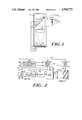
- FIG. 1is a conceptual diagram of the miniature display of a preferred embodiment of the invention.
- FIG. 2is a schematic diagram of a miniaturized display of the type shown in FIG. 1.
- FIGS. 3 and 4are timing diagrams illustrating the pulses appearing at various points in the circuit of FIG. 2.
- FIG. 5is a schematic diagram of an alternative embodiment of the invention.
- FIG. 6is a diagram illustrating an optical configuration for a second alternative embodiment of the invention.
- the display of this inventionis packaged in a light-tight box 12 having a single opening 14 formed therein through which an image may be viewed.
- Box 12is designed to be very small.
- the boxwould be 1-inch by 3-inches with a depth of 1.2 inches.
- Opening 14would be a square hole for viewing the image, each side of the hole being approximately three-quarters of an inch.
- circuit 16containing a plurality of linearly-aligned light-emitting devices 18.
- devices 18are light-emitting diodes ("LEDs").
- LEDslight-emitting diodes
- circuit 16would contain 256 linearly-aligned LEDs.
- the LEDs for this embodimentare approximately 40 microns square with 20 microns space between LEDs.
- An example of a module suitable for use as the circuit 16is the Telefunken TPMP8160 which is a 256 LED printing module.
- Light from LEDs 18is applied to the imaging optics which for the embodiment of FIG. 2 is a magnifying lens 20.
- a 30 mm diameter 50 mm focal length lensis suitable for such use.
- lens 20acts as a simple magnifier. Therefore, if LEDs 18 are located at, or near, the focal point of lens 20, the light emitted from LEDs 18 will be collimated by lens 20 as shown in FIG. 2.
- the collimated light output from lens 20is applied to the vibrating mirror 22 of a resonant scanner 24.
- Scanner 24may for example cause mirror 22 to vibrate through a scan angle of 10° peak to peak at a frequency in the range of 50 to 100 Hz. Vibration through a scan angle of 30° may be possible.
- Mirror 22might for example be one inch square. As mirror 22 is vibrated, the point at which the light from LEDs 18 is projected on the mirror varies. Thus, by selectively illuminating various ones of the LEDs 18 at various points in the vibration of mirror 22, successive rows of pixels (i.e. display spots) will be caused to appear at the mirror. With the mirror being refreshed at a 100 Hz rate (since refresh occurs during movement of the mirror in both directions, the refresh rate is twice the vibration frequency of the mirror), the persistence of the user's eye is sufficient to eliminate flicker and create the illusion of a continuous full page virtual image at the mirror. With a system having the dimensions discussed above, the size of the virtual image at the mirror would be equivalent to a 12-inch diagonal CRT viewed at a distance of 24 inches from the eye. Thus, an image containing 32 lines of 5 ⁇ 7 matrix characters could be easily viewed.
- Optical scanners suitable for use in this inventionare the IB series optical scanners available from General Scanning, Inc., 500 Arsenal Street, Watertown MA 02272.
- Cable 26as will be described in more detail hereinafter, carries control signals for the selective illumination of LEDs 18 and cable 28 provides power to resonant scanner 24 and receives synchronization information from the scanner.
- the information to be displayedis initially stored in data storage device 40.
- storage 40may be a ROM, a PROM, an EPROM or a RAM.
- the read-only storeswould be utilized in applications where a limited set of information is selectively provided to the user. However, for most applications, the information provided to the user will vary with time and environment and with the information the user requests or the information it is determined, either by the user's computer, a host computer, or a supervisory person that the user desires or needs.
- New information to be displayedmay be applied to storage device 40 over data input cable 42 and may be stored in storage device 40 during the delays to be discussed hereinafter which occur at the end of each frame.
- the address at which information is stored in storage device 40 and the address from which information is read outis controlled in conventional fashion by lines 44 from timing and control circuit 46. Data is read out from storage device 40 a row at a time into shift register 48 under control of signals on line 44 from circuit 46. Shift register 48 has for example 256 bit positions, there being a bit position in shift register 48 for each LED 18.
- a strobe signalis applied by circuit 46 over line 50 to cause the contents of shift register 48 to be transferred into latches 54 over cable 56.
- the output of latches 54 on cable 58controls the display drivers in LED circuit 59, the drivers being triggered by a signal on line 52 to illuminate LEDs 18.
- the outputs from LEDs 18are applied through lens 20 to form a display line of pixels at a selected vertical position on mirror 22. As viewed in FIG. 2, the user (not shown) would be inside the figure facing outward.
- the vibration of mirror 22is controlled by mirror drive circuit 60.
- the drive signal applied to mirror 22 over line 62is generally sinusoidal so as to avoid sharp transitions in mirror motion.
- the sinusoidal vibration of mirror 22results in the timing between adjacent rows at the mirror being nonlinear. In the discussion to follow, various techniques will be discussed for dealing with this nonlinearity.
- line Ashows the signal which appears on line 64.
- This signalis high during the scan of the mirror in one direction, which will be called the right scan direction, and is low during a scan in the opposite direction, which will be called the left scan direction.
- the transitions in the signal on line 64 when the direction of vibration of mirror 22 changesmay be utilized to synchronize timing control circuit 46 and thus the remainder of the system. It is further noted that points are being mapped onto mirror 22 during both the left scan and right scan of the mirror. However, the points are being mapped in opposite directions for these two scans.
- the output from left scan delay 68is shown on line C of FIG. 3 and constitutes a series of pulses which are delayed slightly from the beginning of each left scan. As previously indicated, and as may be visible in FIG. 3, the delay for the left scan may be different from the delay for the right scan so as to assure that a point appears at precisely the same point during both scans.
- the spacing between strobe signals on line 52may be varied during a given scan cycle as shown in FIG. 4A.
- the spacing, but not the duration, of the display signals on line 52 which control the LED driversmay also be varied as shown on line B of FIG. 4.
- FIG. 4only representative ones of the strobe and display signals are shown, it being understood that there would be one of each such signal for each row of the display. Thus, for a 256 ⁇ 256 display, there would be 256 of each such signal.
- the illumination from the LEDmay not be uniform. While such nonuniformity may be acceptable for some applications, such nonuniformity could cause a vertical line or stripe to appear in the display in the application of this invention. Since manufacturers typically provide information concerning such nonuniformities with the arrays, such nonuniformities may be compensated for in the circuit of FIG. 2 either by varying the width of the pulses used to energize the LEDs, as shown on line B of FIG. 4, and thus the duration which the LEDs are on, or by varying the current applied to the LEDs to compensate for their nonuniformity. Either technique will result in a substantially uniform illumination from all LEDs of the array regardless of any initial nonuniformities.
- shift register 48, latches 54 and LED circuit 59may be included as part of circuitboard 16.
- mirror drive circuit 60may be included as part of optical scanner 24.
- Timing and control circuit 46may be a programmed microprocessor or other suitable control device. The nature and programming of circuit 46 will vary with application.
- FIG. 5is a schematic diagram of an alternative embodiment of the invention wherein, for purposes of illustration, two rows of light-emitting diodes 18A and 18B are shown, each of which provides an output in a different color.
- light-emitting diodes 18Acould provide a red output and light-emitting diodes 18B a green output.
- one or more additional rows of light-emitting diodesmight be provided.
- the same datawould be loaded into both sets of shift registers but would be loaded into latches 54 for display at slightly different time intervals, the time intervals being correlated to the space between the rows of light-emitting diodes and the rate of travel of the vibrating mirror 22 such that corresponding outputs from light-emitting diodes 18A and 18B are imaged on exactly the same spot on mirror 22. Color images may thus be obtained at mirror 22.
- FIG. 5also illustrates another variation in the system in that, instead of the virtual image at mirror 22 being viewed directly through an opening in box 12, additional optics are provided to create an intermediate real image and then recollimate the light into a small enough beam so that maximum light goes into the user's eye. More particularly, the image from mirror 22 is passed through a lens 80 which forms an intermediate real image at point 82 which is then recollimated by lens 84. Lens 84 could, for example, be set in an eye piece which the viewer could look through.
- FIG. 5operates in the same manner discussed previously in conjunction with the embodiment of FIG. 2.
- FIG. 6is an example of one such optical path which may be utilized to increase light available at the viewing lens.
- light from the light-emitting diodes 18passes through a series of lenses which form the imaging optics to mirror 22.
- the image from the mirroris projected by a pair of fold mirrors 90 and 92 and through various lenses to a viewing lens 94.
- the imaging lenswhich may be a single lens as shown in FIG. 1, is preferably a multiple lens configuration. The exact nature of this lens configuration will vary with application.
- imaging opticscould be used which create the virtual image at any comfortable viewing distance and at any desired size and could be formed either in whole or in part by curved mirrors or other optical elements in addition to or instead of lenses.
- Power to run the various embodiments of the invention indicated abovewould typically be obtained from batteries (not shown). If for the particular application, the power demands are sufficiently low that miniature batteries can be utilized, the batteries can be mounted within the device itself. If larger batteries are required, such batteries could be in a battery pack which the user could, for example, clip to his waist, which pack would be attached through a suitable cable or wire to the device, or it could take some other conventional form. Similarly, a cable or wire could be provided connecting circuit 46 as well as store 40 to an external computer or other control device, permitting both the programming of the display and the data to be displayed, to be varied.
- LEDsare driven from a driver matrix rather than having a separate driver for each LED. This would reduce the time slot for each LED and would result in other changes in the circuitry appropriate for such configurations.
- a display of 256 ⁇ 256has been indicated, it is within the contemplation of the invention that either higher or lower resolution be provided in either direction. It is also possible for the display to be rectangular rather than square.
- the components of the systemmay also be arranged so that the linear array of LEDs represents a vertical column of the display rather than a horizontal row and successive columns of the display are produced as the mirror is vibrated.
- LEDshave been utilized as the light-emitting elements for preferred embodiments, other light-emitting elements, such as linear electroluminescent strips, may be utilized in some applications.
- the LEDs or other light-emitting elementbe aligned in some predetermined fashion other than as a single horizontal or vertical row. For example, the elements could be interlaced in two rows, could be at an angle, or, for appropriate applications could be in a curve, wave array, or other form.
- the electronicswould assure generation of a desired image regardless of the element configuration.
- the box 12may either be a hand-held box which could for example be placed in the user's pocket, or easily fit in a briefcase or purse when not in use, or it could be a small box adapted to be mounted on glasses or goggles for viewing by the user while keeping his hands free.
- the displaysince the display is adjacent to only one eye of the user, and could be positioned out of the user's main line of vision for such eye, it is possible for the user to monitor the display with minimal interruption of the user's normal vision.
- the displayis adapted for use by pilots, machine operators, tank drivers, surgeons or others who require many forms of data input while performing their normal functions, and may provide such information to the user in a form which would be less distracting from his normal function when attempting to view the various dials, gauges and monitors currently used for providing such information.
- the devicecould also be mounted so as to be movable to a position completely out of the user's line of vision when not in use.
- Such configurationmight also permit business or professional people to assimilate required information while driving, sitting on a plane or commuter train, meeting with customers or clients, or performing other functions where it has not heretofore been possible to obtain information in this way. This can be accomplished in a form far more convenient and less bulky than with current lap-top machines and with a display which is far easier to see and read.
- line 42could be connected through suitable circuitry to a TV antenna or other video receiver, permitting the device to be used as a miniature TV monitor.
Landscapes
- Physics & Mathematics (AREA)
- General Physics & Mathematics (AREA)
- Optics & Photonics (AREA)
- Engineering & Computer Science (AREA)
- Multimedia (AREA)
- Signal Processing (AREA)
- Devices For Indicating Variable Information By Combining Individual Elements (AREA)
- Control Of Indicators Other Than Cathode Ray Tubes (AREA)
- Two-Way Televisions, Distribution Of Moving Picture Or The Like (AREA)
Abstract
Description
Claims (45)
Priority Applications (9)
| Application Number | Priority Date | Filing Date | Title |
|---|---|---|---|
| US07/078,295US4934773A (en) | 1987-07-27 | 1987-07-27 | Miniature video display system |
| US07/200,692US5003300A (en) | 1987-07-27 | 1988-05-31 | Head mounted display for miniature video display system |
| AU18940/88AAU611172B2 (en) | 1987-07-27 | 1988-07-11 | Miniature video display system |
| EP88306856AEP0301801B1 (en) | 1987-07-27 | 1988-07-26 | Miniature video display system |
| ES88306856TES2070851T3 (en) | 1987-07-27 | 1988-07-26 | MINIATURE SYSTEM OF VISUAL PRESENTATION IN VIDEO. |
| AT88306856TATE118947T1 (en) | 1987-07-27 | 1988-07-26 | 35mm PICTURE PLAYBACK DEVICE. |
| DE3853108TDE3853108T2 (en) | 1987-07-27 | 1988-07-26 | 35mm display device. |
| CA000573193ACA1315426C (en) | 1987-07-27 | 1988-07-27 | Miniature video display system |
| JP63187929AJP2725788B2 (en) | 1987-07-27 | 1988-07-27 | Small display system and display method |
Applications Claiming Priority (1)
| Application Number | Priority Date | Filing Date | Title |
|---|---|---|---|
| US07/078,295US4934773A (en) | 1987-07-27 | 1987-07-27 | Miniature video display system |
Related Child Applications (1)
| Application Number | Title | Priority Date | Filing Date |
|---|---|---|---|
| US07/200,692Continuation-In-PartUS5003300A (en) | 1987-07-27 | 1988-05-31 | Head mounted display for miniature video display system |
Publications (1)
| Publication Number | Publication Date |
|---|---|
| US4934773Atrue US4934773A (en) | 1990-06-19 |
Family
ID=22143125
Family Applications (1)
| Application Number | Title | Priority Date | Filing Date |
|---|---|---|---|
| US07/078,295Expired - LifetimeUS4934773A (en) | 1987-07-27 | 1987-07-27 | Miniature video display system |
Country Status (8)
| Country | Link |
|---|---|
| US (1) | US4934773A (en) |
| EP (1) | EP0301801B1 (en) |
| JP (1) | JP2725788B2 (en) |
| AT (1) | ATE118947T1 (en) |
| AU (1) | AU611172B2 (en) |
| CA (1) | CA1315426C (en) |
| DE (1) | DE3853108T2 (en) |
| ES (1) | ES2070851T3 (en) |
Cited By (211)
| Publication number | Priority date | Publication date | Assignee | Title |
|---|---|---|---|---|
| US5048077A (en)* | 1988-07-25 | 1991-09-10 | Reflection Technology, Inc. | Telephone handset with full-page visual display |
| AU618986B2 (en)* | 1988-05-31 | 1992-01-16 | Reflection Technology, Inc. | Personal head mounted display |
| US5155615A (en)* | 1988-04-15 | 1992-10-13 | Sharp Kabushiki Kaisha | Miniature display device for use in a miniature electronic apparatus |
| US5180912A (en)* | 1990-09-05 | 1993-01-19 | Gec-Marconi Limited | Display system with means for variably deflecting an array of optical emitters |
| US5192864A (en)* | 1990-09-05 | 1993-03-09 | Gec-Marconi Limited | Two dimensional display produced by one dimensional scanned emitters |
| USD334557S (en) | 1990-10-23 | 1993-04-06 | Reflection Technology, Inc. | Combined headband and attachment arm for a miniature video display box |
| WO1993021673A1 (en)* | 1992-04-21 | 1993-10-28 | Bandgap Technology Corporation | Vertical-cavity surface-emitting laser abray display system |
| US5281960A (en)* | 1991-11-19 | 1994-01-25 | Silhouette Technology, Inc. | Helmet mounted display |
| WO1995006932A1 (en)* | 1993-09-03 | 1995-03-09 | Telefonaktiebolaget Lm Ericsson | Arrangement for image generation and/or reading |
| US5489950A (en)* | 1993-03-16 | 1996-02-06 | Minolta Camera Kabushiki Kaisha | Projection type display system with light emitting arrays and scanning mirror |
| US5495344A (en)* | 1993-10-04 | 1996-02-27 | Motorola, Inc. | Facsimile paging system with virtual display capability and method therefor |
| WO1996006442A3 (en)* | 1994-08-15 | 1996-06-06 | Fed Corp | Body-mountable field emission display device |
| US5526022A (en) | 1993-01-06 | 1996-06-11 | Virtual I/O, Inc. | Sourceless orientation sensor |
| US5614961A (en)* | 1993-02-03 | 1997-03-25 | Nitor | Methods and apparatus for image projection |
| US5619377A (en)* | 1992-02-07 | 1997-04-08 | Virtual I/O, Inc. | Optically corrected helmet mounted display |
| EP0773456A2 (en) | 1995-11-09 | 1997-05-14 | Sharp Kabushiki Kaisha | Magnifying lens and display apparatus |
| US5634201A (en)* | 1995-05-30 | 1997-05-27 | Mooring; Jonathon E. | Communications visor |
| US5648789A (en)* | 1991-10-02 | 1997-07-15 | National Captioning Institute, Inc. | Method and apparatus for closed captioning at a performance |
| US5657165A (en)* | 1995-10-11 | 1997-08-12 | Reflection Technology, Inc. | Apparatus and method for generating full-color images using two light sources |
| US5659327A (en)* | 1992-10-22 | 1997-08-19 | Board Of Regents Of The University Of Washington | Virtual retinal display |
| WO1997032233A1 (en)* | 1996-03-01 | 1997-09-04 | Reflection Technology, Inc. | Split lens video display system |
| US5671076A (en)* | 1994-09-28 | 1997-09-23 | Minolta Co., Ltd. | Image display device using vibrating mirror |
| US5675746A (en)* | 1992-09-30 | 1997-10-07 | Marshall; Paul S. | Virtual reality generator for use with financial information |
| US5688158A (en)* | 1995-08-24 | 1997-11-18 | Fed Corporation | Planarizing process for field emitter displays and other electron source applications |
| US5727098A (en)* | 1994-09-07 | 1998-03-10 | Jacobson; Joseph M. | Oscillating fiber optic display and imager |
| US5742373A (en)* | 1995-10-13 | 1998-04-21 | Massachusetts Institute Of Technology | Color microdisplays and methods of manufacturing same |
| US5751260A (en)* | 1992-01-10 | 1998-05-12 | The United States Of America As Represented By The Secretary Of The Navy | Sensory integrated data interface |
| US5764280A (en)* | 1997-03-20 | 1998-06-09 | Silicon Light Machines Inc. | Display system including an image generator and movable scanner for same |
| US5790099A (en)* | 1994-05-10 | 1998-08-04 | Minolta Co., Ltd. | Display device |
| USD398316S (en) | 1997-08-18 | 1998-09-15 | Thomas Feldman | Magnifying device for the display of a videocassette recorder or stereo |
| US5808591A (en)* | 1994-11-11 | 1998-09-15 | Nintendo Co., Ltd. | Image display device, image display system and program cartridge used therewith |
| WO1998041893A1 (en)* | 1997-03-20 | 1998-09-24 | Silicon Light Machines, Inc. | Display device incorporating one-dimensional high-speed grating light valve array |
| US5815126A (en)* | 1993-10-22 | 1998-09-29 | Kopin Corporation | Monocular portable communication and display system |
| US5821911A (en)* | 1993-09-07 | 1998-10-13 | Motorola | Miniature virtual image color display |
| US5828288A (en)* | 1995-08-24 | 1998-10-27 | Fed Corporation | Pedestal edge emitter and non-linear current limiters for field emitter displays and other electron source applications |
| US5831699A (en)* | 1996-04-29 | 1998-11-03 | Motorola, Inc. | Display with inactive portions and active portions, and having drivers in the inactive portions |
| US5844351A (en)* | 1995-08-24 | 1998-12-01 | Fed Corporation | Field emitter device, and veil process for THR fabrication thereof |
| US5859624A (en)* | 1994-12-02 | 1999-01-12 | Hitachi, Ltd. | Binocular display goggles with a one dimensional light source array scanned to form image of high dot density data |
| US5864326A (en)* | 1992-02-07 | 1999-01-26 | I-O Display Systems Llc | Depixelated visual display |
| US5867134A (en)* | 1995-08-25 | 1999-02-02 | Alvelda; Phillip | VLSI visual display |
| US5903396A (en)* | 1997-10-17 | 1999-05-11 | I/O Display Systems, Llc | Intensified visual display |
| US5903395A (en)* | 1994-08-31 | 1999-05-11 | I-O Display Systems Llc | Personal visual display system |
| US5903243A (en)* | 1993-03-11 | 1999-05-11 | Fed Corporation | Compact, body-mountable field emission display device, and display panel having utility for use therewith |
| US5933125A (en)* | 1995-11-27 | 1999-08-03 | Cae Electronics, Ltd. | Method and apparatus for reducing instability in the display of a virtual environment |
| US5936767A (en)* | 1996-03-18 | 1999-08-10 | Yale University | Multiplanar autostereoscopic imaging system |
| US5973656A (en)* | 1995-07-13 | 1999-10-26 | Nintendo Co., Ltd. | Image display device |
| US5971547A (en)* | 1997-07-22 | 1999-10-26 | Reilley; Peter | Astigmatic lenticular projector system |
| US5977950A (en)* | 1993-11-29 | 1999-11-02 | Motorola, Inc. | Manually controllable cursor in a virtual image |
| US5991087A (en)* | 1993-11-12 | 1999-11-23 | I-O Display System Llc | Non-orthogonal plate in a virtual reality or heads up display |
| US5991085A (en) | 1995-04-21 | 1999-11-23 | I-O Display Systems Llc | Head-mounted personal visual display apparatus with image generator and holder |
| US6005536A (en)* | 1996-01-16 | 1999-12-21 | National Captioning Institute | Captioning glasses |
| US6008781A (en)* | 1992-10-22 | 1999-12-28 | Board Of Regents Of The University Of Washington | Virtual retinal display |
| US6057878A (en)* | 1993-10-26 | 2000-05-02 | Matsushita Electric Industrial Co., Ltd. | Three-dimensional picture image display apparatus |
| US6073034A (en)* | 1996-10-31 | 2000-06-06 | Kopin Corporation | Wireless telephone display system |
| US6088102A (en) | 1997-10-31 | 2000-07-11 | Silicon Light Machines | Display apparatus including grating light-valve array and interferometric optical system |
| US6097543A (en)* | 1992-02-07 | 2000-08-01 | I-O Display Systems Llc | Personal visual display |
| US6101036A (en) | 1998-06-23 | 2000-08-08 | Silicon Light Machines | Embossed diffraction grating alone and in combination with changeable image display |
| US6130770A (en) | 1998-06-23 | 2000-10-10 | Silicon Light Machines | Electron gun activated grating light valve |
| US6137525A (en)* | 1997-02-19 | 2000-10-24 | Lg Electronics Inc. | Personal data communication apparatus |
| US6140981A (en)* | 1997-03-20 | 2000-10-31 | Kuenster; Gordon B. | Body-mountable display system |
| US6160666A (en)* | 1994-02-07 | 2000-12-12 | I-O Display Systems Llc | Personal visual display system |
| US6204974B1 (en) | 1996-10-08 | 2001-03-20 | The Microoptical Corporation | Compact image display system for eyeglasses or other head-borne frames |
| US6215579B1 (en) | 1998-06-24 | 2001-04-10 | Silicon Light Machines | Method and apparatus for modulating an incident light beam for forming a two-dimensional image |
| US6243207B1 (en)* | 1996-11-19 | 2001-06-05 | Sony Corporation | Display apparatus |
| US6243056B1 (en)* | 1993-10-04 | 2001-06-05 | Motorola, Inc. | Transceiver with miniature virtual image display |
| KR100294052B1 (en)* | 2000-08-21 | 2001-06-15 | 김춘호 | Scanning linear array display device using a micro-integrated lens |
| US6271808B1 (en) | 1998-06-05 | 2001-08-07 | Silicon Light Machines | Stereo head mounted display using a single display device |
| US20010017604A1 (en)* | 1996-10-31 | 2001-08-30 | Jeffrey Jacobsen | Reflective microdisplay for portable communication system |
| US6329966B1 (en)* | 1995-10-19 | 2001-12-11 | Mitsubishi Denki Kabushiki Kaisha | Display device employing ultraviolet-beam scanning and color separator |
| US20010054989A1 (en)* | 1993-10-22 | 2001-12-27 | Matthew Zavracky | Color sequential display panels |
| US20020010618A1 (en)* | 2000-01-31 | 2002-01-24 | Rocco Pellegrinelli | Data distribution |
| US6353503B1 (en) | 1999-06-21 | 2002-03-05 | The Micropitical Corporation | Eyeglass display lens system employing off-axis optical design |
| US20020030649A1 (en)* | 1994-03-23 | 2002-03-14 | Kopin Corporation | Wireless communication device having a color sequential display |
| US6359609B1 (en) | 1997-03-20 | 2002-03-19 | Gordon B. Kuenster | Body-mountable display system |
| US6403985B1 (en) | 1991-01-18 | 2002-06-11 | Kopin Corporation | Method of making light emitting diode displays |
| US6421031B1 (en) | 1993-10-22 | 2002-07-16 | Peter A. Ronzani | Camera display system |
| US6424321B1 (en) | 1993-10-22 | 2002-07-23 | Kopin Corporation | Head-mounted matrix display |
| US6448944B2 (en) | 1993-10-22 | 2002-09-10 | Kopin Corporation | Head-mounted matrix display |
| US20020158823A1 (en)* | 1997-10-31 | 2002-10-31 | Matthew Zavracky | Portable microdisplay system |
| US6476784B2 (en) | 1997-10-31 | 2002-11-05 | Kopin Corporation | Portable display system with memory card reader |
| US6512859B2 (en)* | 1997-10-21 | 2003-01-28 | Sokkia Co., Ltd. | Electronic level |
| US6552704B2 (en) | 1997-10-31 | 2003-04-22 | Kopin Corporation | Color display with thin gap liquid crystal |
| US20030090439A1 (en)* | 2001-09-07 | 2003-05-15 | Spitzer Mark B. | Light weight, compact, remountable face-supported electronic display |
| US6583912B1 (en) | 1999-04-13 | 2003-06-24 | Koninklijke Philips Electronics N.V. | Display system with light-emitting elements |
| US6603443B1 (en)* | 1994-12-21 | 2003-08-05 | Three-Five Systems, Inc. | Compact display system controlled by eye position sensory system |
| US6618099B1 (en) | 1999-06-21 | 2003-09-09 | The Microoptical Corporation | Display device with eyepiece assembly and display on opto-mechanical support |
| US6707591B2 (en) | 2001-04-10 | 2004-03-16 | Silicon Light Machines | Angled illumination for a single order light modulator based projection system |
| US6714337B1 (en) | 2002-06-28 | 2004-03-30 | Silicon Light Machines | Method and device for modulating a light beam and having an improved gamma response |
| US6712480B1 (en) | 2002-09-27 | 2004-03-30 | Silicon Light Machines | Controlled curvature of stressed micro-structures |
| US6724354B1 (en) | 1999-06-21 | 2004-04-20 | The Microoptical Corporation | Illumination systems for eyeglass and facemask display systems |
| US6728023B1 (en) | 2002-05-28 | 2004-04-27 | Silicon Light Machines | Optical device arrays with optimized image resolution |
| US6747781B2 (en) | 2001-06-25 | 2004-06-08 | Silicon Light Machines, Inc. | Method, apparatus, and diffuser for reducing laser speckle |
| US6754632B1 (en) | 2000-09-18 | 2004-06-22 | East Carolina University | Methods and devices for delivering exogenously generated speech signals to enhance fluency in persons who stutter |
| US6764875B2 (en) | 1998-07-29 | 2004-07-20 | Silicon Light Machines | Method of and apparatus for sealing an hermetic lid to a semiconductor die |
| US6767751B2 (en) | 2002-05-28 | 2004-07-27 | Silicon Light Machines, Inc. | Integrated driver process flow |
| KR100443765B1 (en)* | 2002-05-23 | 2004-08-21 | 최해용 | 3d visual display system |
| US6782205B2 (en) | 2001-06-25 | 2004-08-24 | Silicon Light Machines | Method and apparatus for dynamic equalization in wavelength division multiplexing |
| US6800238B1 (en) | 2002-01-15 | 2004-10-05 | Silicon Light Machines, Inc. | Method for domain patterning in low coercive field ferroelectrics |
| US6801354B1 (en) | 2002-08-20 | 2004-10-05 | Silicon Light Machines, Inc. | 2-D diffraction grating for substantially eliminating polarization dependent losses |
| US6806997B1 (en) | 2003-02-28 | 2004-10-19 | Silicon Light Machines, Inc. | Patterned diffractive light modulator ribbon for PDL reduction |
| US6813059B2 (en) | 2002-06-28 | 2004-11-02 | Silicon Light Machines, Inc. | Reduced formation of asperities in contact micro-structures |
| US6822797B1 (en) | 2002-05-31 | 2004-11-23 | Silicon Light Machines, Inc. | Light modulator structure for producing high-contrast operation using zero-order light |
| US6829077B1 (en) | 2003-02-28 | 2004-12-07 | Silicon Light Machines, Inc. | Diffractive light modulator with dynamically rotatable diffraction plane |
| US6829092B2 (en) | 2001-08-15 | 2004-12-07 | Silicon Light Machines, Inc. | Blazed grating light valve |
| US6829258B1 (en) | 2002-06-26 | 2004-12-07 | Silicon Light Machines, Inc. | Rapidly tunable external cavity laser |
| US6865346B1 (en) | 2001-06-05 | 2005-03-08 | Silicon Light Machines Corporation | Fiber optic transceiver |
| US6872984B1 (en) | 1998-07-29 | 2005-03-29 | Silicon Light Machines Corporation | Method of sealing a hermetic lid to a semiconductor die at an angle |
| US6908201B2 (en) | 2002-06-28 | 2005-06-21 | Silicon Light Machines Corporation | Micro-support structures |
| US6922272B1 (en) | 2003-02-14 | 2005-07-26 | Silicon Light Machines Corporation | Method and apparatus for leveling thermal stress variations in multi-layer MEMS devices |
| US6922273B1 (en) | 2003-02-28 | 2005-07-26 | Silicon Light Machines Corporation | PDL mitigation structure for diffractive MEMS and gratings |
| US6928207B1 (en) | 2002-12-12 | 2005-08-09 | Silicon Light Machines Corporation | Apparatus for selectively blocking WDM channels |
| US6927891B1 (en) | 2002-12-23 | 2005-08-09 | Silicon Light Machines Corporation | Tilt-able grating plane for improved crosstalk in 1×N blaze switches |
| US6934070B1 (en) | 2002-12-18 | 2005-08-23 | Silicon Light Machines Corporation | Chirped optical MEM device |
| US6947613B1 (en) | 2003-02-11 | 2005-09-20 | Silicon Light Machines Corporation | Wavelength selective switch and equalizer |
| US6956995B1 (en) | 2001-11-09 | 2005-10-18 | Silicon Light Machines Corporation | Optical communication arrangement |
| US6956878B1 (en) | 2000-02-07 | 2005-10-18 | Silicon Light Machines Corporation | Method and apparatus for reducing laser speckle using polarization averaging |
| US20050264502A1 (en)* | 2004-05-07 | 2005-12-01 | Sprague Randall B | Scanned light display system using large numerical aperture light source, method of using same, and method of making scanning mirror assemblies |
| US6987600B1 (en) | 2002-12-17 | 2006-01-17 | Silicon Light Machines Corporation | Arbitrary phase profile for better equalization in dynamic gain equalizer |
| US20060017655A1 (en)* | 2004-07-21 | 2006-01-26 | Microvision, Inc. | Scanned beam system and method using a plurality of display zones |
| US6991953B1 (en) | 2001-09-13 | 2006-01-31 | Silicon Light Machines Corporation | Microelectronic mechanical system and methods |
| US20060061846A1 (en)* | 2004-09-17 | 2006-03-23 | Microvision, Inc. | Scanned light display system using array of collimating elements in conjunction with large numerical aperture light emitter array |
| US7027202B1 (en) | 2003-02-28 | 2006-04-11 | Silicon Light Machines Corp | Silicon substrate as a light modulator sacrificial layer |
| US7031922B1 (en) | 2000-11-20 | 2006-04-18 | East Carolina University | Methods and devices for enhancing fluency in persons who stutter employing visual speech gestures |
| US7042611B1 (en) | 2003-03-03 | 2006-05-09 | Silicon Light Machines Corporation | Pre-deflected bias ribbons |
| US7054515B1 (en) | 2002-05-30 | 2006-05-30 | Silicon Light Machines Corporation | Diffractive light modulator-based dynamic equalizer with integrated spectral monitor |
| US7057819B1 (en) | 2002-12-17 | 2006-06-06 | Silicon Light Machines Corporation | High contrast tilting ribbon blazed grating |
| US7057795B2 (en) | 2002-08-20 | 2006-06-06 | Silicon Light Machines Corporation | Micro-structures with individually addressable ribbon pairs |
| US7068372B1 (en) | 2003-01-28 | 2006-06-27 | Silicon Light Machines Corporation | MEMS interferometer-based reconfigurable optical add-and-drop multiplexor |
| US20060152523A1 (en)* | 2002-11-20 | 2006-07-13 | Seijiro Tomita | Light source device for image display device |
| US7158096B1 (en) | 1999-06-21 | 2007-01-02 | The Microoptical Corporation | Compact, head-mountable display device with suspended eyepiece assembly |
| US7177081B2 (en) | 2001-03-08 | 2007-02-13 | Silicon Light Machines Corporation | High contrast grating light valve type device |
| US7209577B2 (en) | 2005-07-14 | 2007-04-24 | Logitech Europe S.A. | Facial feature-localized and global real-time video morphing |
| US20070167686A1 (en)* | 2003-04-29 | 2007-07-19 | Mcgrath Matthew J | Laryngoscope with camera attachement |
| US20070230794A1 (en)* | 2006-04-04 | 2007-10-04 | Logitech Europe S.A. | Real-time automatic facial feature replacement |
| US7286764B1 (en) | 2003-02-03 | 2007-10-23 | Silicon Light Machines Corporation | Reconfigurable modulator-based optical add-and-drop multiplexer |
| US7321354B1 (en) | 1996-10-31 | 2008-01-22 | Kopin Corporation | Microdisplay for portable communication systems |
| US20080018641A1 (en)* | 2006-03-07 | 2008-01-24 | Sprague Randall B | Display configured for varying the apparent depth of selected pixels |
| US20080043487A1 (en)* | 2006-08-21 | 2008-02-21 | Sprague Randall B | Light bar structure having light conduits and scanned light display system employing same |
| US20080064326A1 (en)* | 2006-08-24 | 2008-03-13 | Stephen Joseph Foster | Systems and Methods for Casting Captions Associated With A Media Stream To A User |
| US7372447B1 (en) | 1996-10-31 | 2008-05-13 | Kopin Corporation | Microdisplay for portable communication systems |
| US7391973B1 (en) | 2003-02-28 | 2008-06-24 | Silicon Light Machines Corporation | Two-stage gain equalizer |
| US20080255458A1 (en)* | 2007-04-13 | 2008-10-16 | Ethicon Endo-Surgery, Inc. | System and method using fluorescence to examine within a patient's anatomy |
| US20080259228A1 (en)* | 1997-04-14 | 2008-10-23 | Dicon A/S | Apparatus and a method for illuminating a light-sensitive medium |
| US7466992B1 (en) | 2001-10-18 | 2008-12-16 | Iwao Fujisaki | Communication device |
| US7526279B1 (en) | 2001-10-18 | 2009-04-28 | Corydoras Technologies, Llc | Communication device |
| US7561317B2 (en) | 2006-11-03 | 2009-07-14 | Ethicon Endo-Surgery, Inc. | Resonant Fourier scanning |
| US7589316B2 (en) | 2007-01-18 | 2009-09-15 | Ethicon Endo-Surgery, Inc. | Scanning beam imaging with adjustable detector sensitivity or gain |
| US7713265B2 (en) | 2006-12-22 | 2010-05-11 | Ethicon Endo-Surgery, Inc. | Apparatus and method for medically treating a tattoo |
| US7778664B1 (en) | 2001-10-18 | 2010-08-17 | Iwao Fujisaki | Communication device |
| US7856248B1 (en) | 2003-09-26 | 2010-12-21 | Iwao Fujisaki | Communication device |
| US7890089B1 (en) | 2007-05-03 | 2011-02-15 | Iwao Fujisaki | Communication device |
| US7917167B1 (en) | 2003-11-22 | 2011-03-29 | Iwao Fujisaki | Communication device |
| US7925333B2 (en) | 2007-08-28 | 2011-04-12 | Ethicon Endo-Surgery, Inc. | Medical device including scanned beam unit with operational control features |
| US7982776B2 (en) | 2007-07-13 | 2011-07-19 | Ethicon Endo-Surgery, Inc. | SBI motion artifact removal apparatus and method |
| US7983739B2 (en) | 2007-08-27 | 2011-07-19 | Ethicon Endo-Surgery, Inc. | Position tracking and control for a scanning assembly |
| US7995045B2 (en) | 2007-04-13 | 2011-08-09 | Ethicon Endo-Surgery, Inc. | Combined SBI and conventional image processor |
| US20110221672A1 (en)* | 2010-02-28 | 2011-09-15 | Osterhout Group, Inc. | Hand-worn control device in an augmented reality eyepiece |
| US8041348B1 (en) | 2004-03-23 | 2011-10-18 | Iwao Fujisaki | Communication device |
| US8050520B2 (en) | 2008-03-27 | 2011-11-01 | Ethicon Endo-Surgery, Inc. | Method for creating a pixel image from sampled data of a scanned beam imager |
| US8160678B2 (en) | 2007-06-18 | 2012-04-17 | Ethicon Endo-Surgery, Inc. | Methods and devices for repairing damaged or diseased tissue using a scanning beam assembly |
| US8208954B1 (en) | 2005-04-08 | 2012-06-26 | Iwao Fujisaki | Communication device |
| US8216214B2 (en) | 2007-03-12 | 2012-07-10 | Ethicon Endo-Surgery, Inc. | Power modulation of a scanning beam for imaging, therapy, and/or diagnosis |
| US8229512B1 (en) | 2003-02-08 | 2012-07-24 | Iwao Fujisaki | Communication device |
| US8241128B1 (en) | 2003-04-03 | 2012-08-14 | Iwao Fujisaki | Communication device |
| US8273015B2 (en) | 2007-01-09 | 2012-09-25 | Ethicon Endo-Surgery, Inc. | Methods for imaging the anatomy with an anatomically secured scanner assembly |
| US8332014B2 (en) | 2008-04-25 | 2012-12-11 | Ethicon Endo-Surgery, Inc. | Scanned beam device and method using same which measures the reflectance of patient tissue |
| US8340726B1 (en) | 2008-06-30 | 2012-12-25 | Iwao Fujisaki | Communication device |
| US8452307B1 (en) | 2008-07-02 | 2013-05-28 | Iwao Fujisaki | Communication device |
| US8467133B2 (en) | 2010-02-28 | 2013-06-18 | Osterhout Group, Inc. | See-through display with an optical assembly including a wedge-shaped illumination system |
| US8472935B1 (en) | 2007-10-29 | 2013-06-25 | Iwao Fujisaki | Communication device |
| US8472120B2 (en) | 2010-02-28 | 2013-06-25 | Osterhout Group, Inc. | See-through near-eye display glasses with a small scale image source |
| US8477425B2 (en) | 2010-02-28 | 2013-07-02 | Osterhout Group, Inc. | See-through near-eye display glasses including a partially reflective, partially transmitting optical element |
| US8482859B2 (en) | 2010-02-28 | 2013-07-09 | Osterhout Group, Inc. | See-through near-eye display glasses wherein image light is transmitted to and reflected from an optically flat film |
| US8488246B2 (en) | 2010-02-28 | 2013-07-16 | Osterhout Group, Inc. | See-through near-eye display glasses including a curved polarizing film in the image source, a partially reflective, partially transmitting optical element and an optically flat film |
| US8543157B1 (en) | 2008-05-09 | 2013-09-24 | Iwao Fujisaki | Communication device which notifies its pin-point location or geographic area in accordance with user selection |
| KR101310056B1 (en) | 2004-12-23 | 2013-09-24 | 돌비 레버러토리즈 라이쎈싱 코오포레이션 | Wide color gamut displays |
| US8639214B1 (en) | 2007-10-26 | 2014-01-28 | Iwao Fujisaki | Communication device |
| US8676273B1 (en) | 2007-08-24 | 2014-03-18 | Iwao Fujisaki | Communication device |
| US8801606B2 (en) | 2007-01-09 | 2014-08-12 | Ethicon Endo-Surgery, Inc. | Method of in vivo monitoring using an imaging system including scanned beam imaging unit |
| US8825090B1 (en) | 2007-05-03 | 2014-09-02 | Iwao Fujisaki | Communication device |
| US9079762B2 (en) | 2006-09-22 | 2015-07-14 | Ethicon Endo-Surgery, Inc. | Micro-electromechanical device |
| US9091851B2 (en) | 2010-02-28 | 2015-07-28 | Microsoft Technology Licensing, Llc | Light control in head mounted displays |
| US9097891B2 (en) | 2010-02-28 | 2015-08-04 | Microsoft Technology Licensing, Llc | See-through near-eye display glasses including an auto-brightness control for the display brightness based on the brightness in the environment |
| US9097890B2 (en) | 2010-02-28 | 2015-08-04 | Microsoft Technology Licensing, Llc | Grating in a light transmissive illumination system for see-through near-eye display glasses |
| US9128281B2 (en) | 2010-09-14 | 2015-09-08 | Microsoft Technology Licensing, Llc | Eyepiece with uniformly illuminated reflective display |
| US9125552B2 (en) | 2007-07-31 | 2015-09-08 | Ethicon Endo-Surgery, Inc. | Optical scanning module and means for attaching the module to medical instruments for introducing the module into the anatomy |
| US9129295B2 (en) | 2010-02-28 | 2015-09-08 | Microsoft Technology Licensing, Llc | See-through near-eye display glasses with a fast response photochromic film system for quick transition from dark to clear |
| US9134534B2 (en) | 2010-02-28 | 2015-09-15 | Microsoft Technology Licensing, Llc | See-through near-eye display glasses including a modular image source |
| US9139089B1 (en) | 2007-12-27 | 2015-09-22 | Iwao Fujisaki | Inter-vehicle middle point maintaining implementer |
| US9182596B2 (en) | 2010-02-28 | 2015-11-10 | Microsoft Technology Licensing, Llc | See-through near-eye display glasses with the optical assembly including absorptive polarizers or anti-reflective coatings to reduce stray light |
| US9213405B2 (en) | 2010-12-16 | 2015-12-15 | Microsoft Technology Licensing, Llc | Comprehension and intent-based content for augmented reality displays |
| US9223134B2 (en) | 2010-02-28 | 2015-12-29 | Microsoft Technology Licensing, Llc | Optical imperfections in a light transmissive illumination system for see-through near-eye display glasses |
| US9229227B2 (en) | 2010-02-28 | 2016-01-05 | Microsoft Technology Licensing, Llc | See-through near-eye display glasses with a light transmissive wedge shaped illumination system |
| US9285589B2 (en) | 2010-02-28 | 2016-03-15 | Microsoft Technology Licensing, Llc | AR glasses with event and sensor triggered control of AR eyepiece applications |
| US9292973B2 (en) | 2010-11-08 | 2016-03-22 | Microsoft Technology Licensing, Llc | Automatic variable virtual focus for augmented reality displays |
| US9304319B2 (en) | 2010-11-18 | 2016-04-05 | Microsoft Technology Licensing, Llc | Automatic focus improvement for augmented reality displays |
| US9323325B2 (en) | 2011-08-30 | 2016-04-26 | Microsoft Technology Licensing, Llc | Enhancing an object of interest in a see-through, mixed reality display device |
| US9341843B2 (en) | 2010-02-28 | 2016-05-17 | Microsoft Technology Licensing, Llc | See-through near-eye display glasses with a small scale image source |
| US9366862B2 (en) | 2010-02-28 | 2016-06-14 | Microsoft Technology Licensing, Llc | System and method for delivering content to a group of see-through near eye display eyepieces |
| US9759917B2 (en) | 2010-02-28 | 2017-09-12 | Microsoft Technology Licensing, Llc | AR glasses with event and sensor triggered AR eyepiece interface to external devices |
| US10180572B2 (en) | 2010-02-28 | 2019-01-15 | Microsoft Technology Licensing, Llc | AR glasses with event and user action control of external applications |
| US10223832B2 (en) | 2011-08-17 | 2019-03-05 | Microsoft Technology Licensing, Llc | Providing location occupancy analysis via a mixed reality device |
| US20190258313A1 (en)* | 2016-11-07 | 2019-08-22 | Changchun Ruixinboguan Technology Development Co., Ltd. | Systems and methods for interaction with an application |
| US10539787B2 (en) | 2010-02-28 | 2020-01-21 | Microsoft Technology Licensing, Llc | Head-worn adaptive display |
| US10860100B2 (en) | 2010-02-28 | 2020-12-08 | Microsoft Technology Licensing, Llc | AR glasses with predictive control of external device based on event input |
| USD914019S1 (en)* | 2019-01-04 | 2021-03-23 | Zhuhai RAVV Technology Co., Ltd. | Artificial intelligence headphone with optical integrated glasses for augmented reality |
| US11127210B2 (en) | 2011-08-24 | 2021-09-21 | Microsoft Technology Licensing, Llc | Touch and social cues as inputs into a computer |
| WO2021206875A1 (en)* | 2020-03-16 | 2021-10-14 | Auroratech Company | Display driver ic (ddic) backplane for scanning microled array |
| US20230393654A1 (en)* | 2022-06-03 | 2023-12-07 | Valve Corporation | Optical tracking including imaging-based angle sensitive detectors |
| US11841554B2 (en) | 2021-04-29 | 2023-12-12 | Brandon Gaynor | Eyewear interface assembly |
| WO2024089389A1 (en) | 2022-10-24 | 2024-05-02 | Neil Newell | Display |
Families Citing this family (14)
| Publication number | Priority date | Publication date | Assignee | Title |
|---|---|---|---|---|
| US4902083A (en)* | 1988-05-31 | 1990-02-20 | Reflection Technology, Inc. | Low vibration resonant scanning unit for miniature optical display apparatus |
| US5023905A (en)* | 1988-07-25 | 1991-06-11 | Reflection Technology, Inc. | Pocket data receiver with full page visual display |
| US5032924A (en)* | 1989-04-10 | 1991-07-16 | Nilford Laboratories, Inc. | System for producing an image from a sequence of pixels |
| US5033814A (en)* | 1989-04-10 | 1991-07-23 | Nilford Laboratories, Inc. | Line light source |
| WO1991008646A1 (en)* | 1989-11-30 | 1991-06-13 | Malcolm Grant Wittey | Display devices |
| US5040058A (en)* | 1989-12-26 | 1991-08-13 | General Electric Company | Raster graphic helmet mountable display |
| DE69123288T2 (en)* | 1990-05-21 | 1997-04-24 | Victor Company Of Japan | Display device |
| US5189512A (en)* | 1991-07-01 | 1993-02-23 | Camair Research, Inc. | Helmet integrated display system |
| TW269094B (en) | 1994-11-11 | 1996-01-21 | Nitendo Kk | Three dimensional visual image display device and electric game apparatus, memory device thereof |
| JPH08136855A (en)* | 1994-11-11 | 1996-05-31 | Nintendo Co Ltd | Image display device, image display system and program cartridge used therefor |
| CA2386856A1 (en) | 1999-10-14 | 2001-04-19 | Stratos Product Development Llc | Virtual imaging system |
| CN101023387A (en) | 2004-04-01 | 2007-08-22 | 西门子公司 | Determining the excursion of micromirrors in a projection system |
| US20090322800A1 (en) | 2008-06-25 | 2009-12-31 | Dolby Laboratories Licensing Corporation | Method and apparatus in various embodiments for hdr implementation in display devices |
| CN110658622A (en)* | 2019-08-19 | 2020-01-07 | 深圳市矽赫科技有限公司 | Automatic-adjustment micro-display optical eyepiece and adjustment method thereof |
Citations (28)
| Publication number | Priority date | Publication date | Assignee | Title |
|---|---|---|---|---|
| US28847A (en)* | 1860-06-26 | Improvement in corn-planters | ||
| US3059519A (en)* | 1956-09-05 | 1962-10-23 | Austin N Stanton | Headgear mounted cathode ray tube and binocular viewing device |
| US3170979A (en)* | 1962-04-30 | 1965-02-23 | Alan W Baldwin | Optical image interposing display device |
| US3205303A (en)* | 1961-03-27 | 1965-09-07 | Philco Corp | Remotely controlled remote viewing system |
| US3671766A (en)* | 1970-06-29 | 1972-06-20 | Hughes Aircraft Co | Oscillating mechanism |
| US3742238A (en)* | 1970-12-14 | 1973-06-26 | Texas Instruments Inc | Two axes angularly indexing scanning display |
| US3760181A (en)* | 1972-03-03 | 1973-09-18 | Us Army | Universal viewer for far infrared |
| US3781559A (en)* | 1972-06-19 | 1973-12-25 | Texas Instruments Inc | Variable field of view scanning system |
| US3833300A (en)* | 1973-05-14 | 1974-09-03 | Us Navy | Three {37 d{38 {11 weapons sight |
| US3923370A (en)* | 1974-10-15 | 1975-12-02 | Honeywell Inc | Head mounted displays |
| US3958235A (en)* | 1974-07-26 | 1976-05-18 | Duffy Francis A | Light emitting diode display apparatus and system |
| USRE28847E (en) | 1972-06-28 | 1976-06-08 | Honeywell Inc. | Inside helmet sight display apparatus |
| US4026641A (en)* | 1975-12-30 | 1977-05-31 | The United States Of America As Represented By The Secretary Of The Army | Toric reflector display |
| US4081209A (en)* | 1975-04-29 | 1978-03-28 | Elliott Brothers (London) Limited | Headgear with spherical semi-reflecting surface |
| US4225862A (en)* | 1979-03-05 | 1980-09-30 | International Business Machines Corporation | Tuning fork oscillator driven light emitting diode display unit |
| US4248495A (en)* | 1978-05-08 | 1981-02-03 | Canon Kabushiki Kaisha | Projecting optical system with deflected optical axis maintained parallel to next optical axis |
| US4251126A (en)* | 1978-06-06 | 1981-02-17 | Canon Kabushiki Kaisha | Light beam scanning device with opposed deflecting surfaces |
| US4340888A (en)* | 1980-04-01 | 1982-07-20 | Martin Marietta Corporation | Scan linerization method and device |
| US4439157A (en)* | 1982-05-03 | 1984-03-27 | The United States Of America As Represented By The Secretary Of The Navy | Helmet mounted display projector |
| US4443075A (en)* | 1981-06-26 | 1984-04-17 | Sri International | Stabilized visual system |
| US4457580A (en)* | 1980-07-11 | 1984-07-03 | Mattel, Inc. | Display for electronic games and the like including a rotating focusing device |
| US4470044A (en)* | 1981-05-15 | 1984-09-04 | Bill Bell | Momentary visual image apparatus |
| US4477727A (en)* | 1982-09-27 | 1984-10-16 | The Singer Company | Beam position detection system for use in an optical scanning system |
| US4538181A (en)* | 1983-02-28 | 1985-08-27 | Kollmorgen Technologies | Optical scanner |
| US4632501A (en)* | 1984-02-16 | 1986-12-30 | General Scanning, Inc. | Resonant electromechanical oscillator |
| US4636866A (en)* | 1982-12-24 | 1987-01-13 | Seiko Epson K.K. | Personal liquid crystal image display |
| US4676582A (en)* | 1982-02-18 | 1987-06-30 | Fuji Photo Film Co., Ltd. | Radiation image read-out and reproducing apparatus |
| US4750486A (en)* | 1985-08-14 | 1988-06-14 | Butler Philip H | Apparatus for moving a mirror |
Family Cites Families (6)
| Publication number | Priority date | Publication date | Assignee | Title |
|---|---|---|---|---|
| JPS5331698Y2 (en)* | 1973-05-19 | 1978-08-07 | ||
| US4323920A (en)* | 1980-05-19 | 1982-04-06 | Collender Robert B | Stereoscopic television (unaided with lip sync) on standard bandwidth-method and apparatus |
| GB2119196A (en)* | 1981-12-15 | 1983-11-09 | Secr Defence | A direct view thermal imager |
| BR8307566A (en)* | 1982-10-14 | 1984-08-28 | Arnvid Sakariassen | TELEVISION DEVICE |
| GB2142203B (en)* | 1983-06-21 | 1986-12-17 | Sira Ltd | Television projection apparatus |
| US5003300A (en)* | 1987-07-27 | 1991-03-26 | Reflection Technology, Inc. | Head mounted display for miniature video display system |
- 1987
- 1987-07-27USUS07/078,295patent/US4934773A/ennot_activeExpired - Lifetime
- 1988
- 1988-07-11AUAU18940/88Apatent/AU611172B2/ennot_activeCeased
- 1988-07-26DEDE3853108Tpatent/DE3853108T2/ennot_activeExpired - Fee Related
- 1988-07-26ATAT88306856Tpatent/ATE118947T1/ennot_activeIP Right Cessation
- 1988-07-26ESES88306856Tpatent/ES2070851T3/ennot_activeExpired - Lifetime
- 1988-07-26EPEP88306856Apatent/EP0301801B1/ennot_activeExpired - Lifetime
- 1988-07-27JPJP63187929Apatent/JP2725788B2/ennot_activeExpired - Lifetime
- 1988-07-27CACA000573193Apatent/CA1315426C/ennot_activeExpired - Fee Related
Patent Citations (28)
| Publication number | Priority date | Publication date | Assignee | Title |
|---|---|---|---|---|
| US28847A (en)* | 1860-06-26 | Improvement in corn-planters | ||
| US3059519A (en)* | 1956-09-05 | 1962-10-23 | Austin N Stanton | Headgear mounted cathode ray tube and binocular viewing device |
| US3205303A (en)* | 1961-03-27 | 1965-09-07 | Philco Corp | Remotely controlled remote viewing system |
| US3170979A (en)* | 1962-04-30 | 1965-02-23 | Alan W Baldwin | Optical image interposing display device |
| US3671766A (en)* | 1970-06-29 | 1972-06-20 | Hughes Aircraft Co | Oscillating mechanism |
| US3742238A (en)* | 1970-12-14 | 1973-06-26 | Texas Instruments Inc | Two axes angularly indexing scanning display |
| US3760181A (en)* | 1972-03-03 | 1973-09-18 | Us Army | Universal viewer for far infrared |
| US3781559A (en)* | 1972-06-19 | 1973-12-25 | Texas Instruments Inc | Variable field of view scanning system |
| USRE28847E (en) | 1972-06-28 | 1976-06-08 | Honeywell Inc. | Inside helmet sight display apparatus |
| US3833300A (en)* | 1973-05-14 | 1974-09-03 | Us Navy | Three {37 d{38 {11 weapons sight |
| US3958235A (en)* | 1974-07-26 | 1976-05-18 | Duffy Francis A | Light emitting diode display apparatus and system |
| US3923370A (en)* | 1974-10-15 | 1975-12-02 | Honeywell Inc | Head mounted displays |
| US4081209A (en)* | 1975-04-29 | 1978-03-28 | Elliott Brothers (London) Limited | Headgear with spherical semi-reflecting surface |
| US4026641A (en)* | 1975-12-30 | 1977-05-31 | The United States Of America As Represented By The Secretary Of The Army | Toric reflector display |
| US4248495A (en)* | 1978-05-08 | 1981-02-03 | Canon Kabushiki Kaisha | Projecting optical system with deflected optical axis maintained parallel to next optical axis |
| US4251126A (en)* | 1978-06-06 | 1981-02-17 | Canon Kabushiki Kaisha | Light beam scanning device with opposed deflecting surfaces |
| US4225862A (en)* | 1979-03-05 | 1980-09-30 | International Business Machines Corporation | Tuning fork oscillator driven light emitting diode display unit |
| US4340888A (en)* | 1980-04-01 | 1982-07-20 | Martin Marietta Corporation | Scan linerization method and device |
| US4457580A (en)* | 1980-07-11 | 1984-07-03 | Mattel, Inc. | Display for electronic games and the like including a rotating focusing device |
| US4470044A (en)* | 1981-05-15 | 1984-09-04 | Bill Bell | Momentary visual image apparatus |
| US4443075A (en)* | 1981-06-26 | 1984-04-17 | Sri International | Stabilized visual system |
| US4676582A (en)* | 1982-02-18 | 1987-06-30 | Fuji Photo Film Co., Ltd. | Radiation image read-out and reproducing apparatus |
| US4439157A (en)* | 1982-05-03 | 1984-03-27 | The United States Of America As Represented By The Secretary Of The Navy | Helmet mounted display projector |
| US4477727A (en)* | 1982-09-27 | 1984-10-16 | The Singer Company | Beam position detection system for use in an optical scanning system |
| US4636866A (en)* | 1982-12-24 | 1987-01-13 | Seiko Epson K.K. | Personal liquid crystal image display |
| US4538181A (en)* | 1983-02-28 | 1985-08-27 | Kollmorgen Technologies | Optical scanner |
| US4632501A (en)* | 1984-02-16 | 1986-12-30 | General Scanning, Inc. | Resonant electromechanical oscillator |
| US4750486A (en)* | 1985-08-14 | 1988-06-14 | Butler Philip H | Apparatus for moving a mirror |
Non-Patent Citations (12)
| Title |
|---|
| IBM Technical Disclosure Bulletin, vol. 22, No. 1, Jun. 1979, "Projected Image Display", N. M. Leon. |
| IBM Technical Disclosure Bulletin, vol. 22, No. 1, Jun. 1979, Projected Image Display , N. M. Leon.* |
| Reid, D. A. T., "Micro-Display", 6/79, IBM Technical Disclosure Bulletin, vol. 22, No. 1, pp. 362-365. |
| Reid, D. A. T., Micro Display , 6/79, IBM Technical Disclosure Bulletin, vol. 22, No. 1, pp. 362 365.* |
| Title "High-Resolution Display Using Light-Emitting Diode Arrays", vol. 52, pp. 46-51, by Ichimatsu Abiko and Akira Nomura, Jan./86. |
| Title "IRTV-445 Patented Scanning System". |
| Title High Resolution Display Using Light Emitting Diode Arrays , vol. 52, pp. 46 51, by Ichimatsu Abiko and Akira Nomura, Jan./86.* |
| Title IRTV 445 Patented Scanning System .* |
| Upton, Hubert W. and Goodman, J. R., "Eyeglass Heads-Up Display", Proceedings of the SID, vol. 23/2, 1982, pp. 77-80. |
| Upton, Hubert W. and Goodman, J. R., Eyeglass Heads Up Display , Proceedings of the SID, vol. 23/2, 1982, pp. 77 80.* |
| Upton, Hubert W. and Goodman, James R., "Eyeglass Heads-Up Display", SID 81 Digest, pp. 48, 49. |
| Upton, Hubert W. and Goodman, James R., Eyeglass Heads Up Display , SID 81 Digest, pp. 48, 49.* |
Cited By (420)
| Publication number | Priority date | Publication date | Assignee | Title |
|---|---|---|---|---|
| US5155615A (en)* | 1988-04-15 | 1992-10-13 | Sharp Kabushiki Kaisha | Miniature display device for use in a miniature electronic apparatus |
| AU618986B2 (en)* | 1988-05-31 | 1992-01-16 | Reflection Technology, Inc. | Personal head mounted display |
| US5048077A (en)* | 1988-07-25 | 1991-09-10 | Reflection Technology, Inc. | Telephone handset with full-page visual display |
| US5180912A (en)* | 1990-09-05 | 1993-01-19 | Gec-Marconi Limited | Display system with means for variably deflecting an array of optical emitters |
| US5192864A (en)* | 1990-09-05 | 1993-03-09 | Gec-Marconi Limited | Two dimensional display produced by one dimensional scanned emitters |
| USD334557S (en) | 1990-10-23 | 1993-04-06 | Reflection Technology, Inc. | Combined headband and attachment arm for a miniature video display box |
| US6403985B1 (en) | 1991-01-18 | 2002-06-11 | Kopin Corporation | Method of making light emitting diode displays |
| US20030020084A1 (en)* | 1991-01-18 | 2003-01-30 | Kopin Corporation | Method of making light emitting diode displays |
| US5648789A (en)* | 1991-10-02 | 1997-07-15 | National Captioning Institute, Inc. | Method and apparatus for closed captioning at a performance |
| US5281960A (en)* | 1991-11-19 | 1994-01-25 | Silhouette Technology, Inc. | Helmet mounted display |
| US5751260A (en)* | 1992-01-10 | 1998-05-12 | The United States Of America As Represented By The Secretary Of The Navy | Sensory integrated data interface |
| US5864326A (en)* | 1992-02-07 | 1999-01-26 | I-O Display Systems Llc | Depixelated visual display |
| US5949583A (en)* | 1992-02-07 | 1999-09-07 | I-O Display Systems Llc | Head-mounted display with image generator, fold mirror and mirror for transmission to the eye position of the user |
| US5619377A (en)* | 1992-02-07 | 1997-04-08 | Virtual I/O, Inc. | Optically corrected helmet mounted display |
| US5673151A (en)* | 1992-02-07 | 1997-09-30 | Virtual I/O | Image correction in virtual reality and heads up displays |
| US6097543A (en)* | 1992-02-07 | 2000-08-01 | I-O Display Systems Llc | Personal visual display |
| US5642227A (en)* | 1992-02-07 | 1997-06-24 | Virtual I/O, Inc. | Optical correction for virtual reality and heads up displays |
| US5325386A (en)* | 1992-04-21 | 1994-06-28 | Bandgap Technology Corporation | Vertical-cavity surface emitting laser assay display system |
| WO1993021673A1 (en)* | 1992-04-21 | 1993-10-28 | Bandgap Technology Corporation | Vertical-cavity surface-emitting laser abray display system |
| US5774878A (en)* | 1992-09-30 | 1998-06-30 | Marshall; Paul Steven | Virtual reality generator for use with financial information |
| US5675746A (en)* | 1992-09-30 | 1997-10-07 | Marshall; Paul S. | Virtual reality generator for use with financial information |
| US20020178096A1 (en)* | 1992-09-30 | 2002-11-28 | Marshall Paul Steven | Virtual reality generator for use with financial information |
| US6073115A (en)* | 1992-09-30 | 2000-06-06 | Marshall; Paul Steven | Virtual reality generator for displaying abstract information |
| US6008781A (en)* | 1992-10-22 | 1999-12-28 | Board Of Regents Of The University Of Washington | Virtual retinal display |
| US20030095081A1 (en)* | 1992-10-22 | 2003-05-22 | University Of Washington | Display with variably transmissive element |
| US20020163484A1 (en)* | 1992-10-22 | 2002-11-07 | University Of Washington | Display with variably transmissive element |
| US6317103B1 (en)* | 1992-10-22 | 2001-11-13 | University Of Washington | Virtual retinal display and method for tracking eye position |
| US6639570B2 (en)* | 1992-10-22 | 2003-10-28 | University Of Washington | Retinal display scanning of image with plurality of image sectors |
| US5659327A (en)* | 1992-10-22 | 1997-08-19 | Board Of Regents Of The University Of Washington | Virtual retinal display |
| US5526022A (en) | 1993-01-06 | 1996-06-11 | Virtual I/O, Inc. | Sourceless orientation sensor |
| US5920361A (en)* | 1993-02-03 | 1999-07-06 | Nitor | Methods and apparatus for image projection |
| US5715021A (en)* | 1993-02-03 | 1998-02-03 | Nitor | Methods and apparatus for image projection |
| US5614961A (en)* | 1993-02-03 | 1997-03-25 | Nitor | Methods and apparatus for image projection |
| US5903243A (en)* | 1993-03-11 | 1999-05-11 | Fed Corporation | Compact, body-mountable field emission display device, and display panel having utility for use therewith |
| US5489950A (en)* | 1993-03-16 | 1996-02-06 | Minolta Camera Kabushiki Kaisha | Projection type display system with light emitting arrays and scanning mirror |
| US5541401A (en)* | 1993-09-03 | 1996-07-30 | Telefonaktiebolaget Lm Ericsson | Arrangement for image generation and/or reading having pixel matrices of differing densities |
| WO1995006932A1 (en)* | 1993-09-03 | 1995-03-09 | Telefonaktiebolaget Lm Ericsson | Arrangement for image generation and/or reading |
| US5821911A (en)* | 1993-09-07 | 1998-10-13 | Motorola | Miniature virtual image color display |
| US6243056B1 (en)* | 1993-10-04 | 2001-06-05 | Motorola, Inc. | Transceiver with miniature virtual image display |
| US5495344A (en)* | 1993-10-04 | 1996-02-27 | Motorola, Inc. | Facsimile paging system with virtual display capability and method therefor |
| US20010054989A1 (en)* | 1993-10-22 | 2001-12-27 | Matthew Zavracky | Color sequential display panels |
| US20080122736A1 (en)* | 1993-10-22 | 2008-05-29 | Kopin Corporation | Portable communication display device |
| US8040292B2 (en) | 1993-10-22 | 2011-10-18 | Kopin Corporation | Portable communication display device |
| US5815126A (en)* | 1993-10-22 | 1998-09-29 | Kopin Corporation | Monocular portable communication and display system |
| US6683584B2 (en) | 1993-10-22 | 2004-01-27 | Kopin Corporation | Camera display system |
| US6421031B1 (en) | 1993-10-22 | 2002-07-16 | Peter A. Ronzani | Camera display system |
| US7310072B2 (en) | 1993-10-22 | 2007-12-18 | Kopin Corporation | Portable communication display device |
| US6424321B1 (en) | 1993-10-22 | 2002-07-23 | Kopin Corporation | Head-mounted matrix display |
| US6448944B2 (en) | 1993-10-22 | 2002-09-10 | Kopin Corporation | Head-mounted matrix display |
| US6452572B1 (en) | 1993-10-22 | 2002-09-17 | Kopin Corporation | Monocular head-mounted display system |
| US6057878A (en)* | 1993-10-26 | 2000-05-02 | Matsushita Electric Industrial Co., Ltd. | Three-dimensional picture image display apparatus |
| US5991087A (en)* | 1993-11-12 | 1999-11-23 | I-O Display System Llc | Non-orthogonal plate in a virtual reality or heads up display |
| US5977950A (en)* | 1993-11-29 | 1999-11-02 | Motorola, Inc. | Manually controllable cursor in a virtual image |
| US6160666A (en)* | 1994-02-07 | 2000-12-12 | I-O Display Systems Llc | Personal visual display system |
| US20020030649A1 (en)* | 1994-03-23 | 2002-03-14 | Kopin Corporation | Wireless communication device having a color sequential display |
| US5790099A (en)* | 1994-05-10 | 1998-08-04 | Minolta Co., Ltd. | Display device |
| WO1996006442A3 (en)* | 1994-08-15 | 1996-06-06 | Fed Corp | Body-mountable field emission display device |
| US5903395A (en)* | 1994-08-31 | 1999-05-11 | I-O Display Systems Llc | Personal visual display system |
| US5727098A (en)* | 1994-09-07 | 1998-03-10 | Jacobson; Joseph M. | Oscillating fiber optic display and imager |
| US5671076A (en)* | 1994-09-28 | 1997-09-23 | Minolta Co., Ltd. | Image display device using vibrating mirror |
| US5808591A (en)* | 1994-11-11 | 1998-09-15 | Nintendo Co., Ltd. | Image display device, image display system and program cartridge used therewith |
| US5859624A (en)* | 1994-12-02 | 1999-01-12 | Hitachi, Ltd. | Binocular display goggles with a one dimensional light source array scanned to form image of high dot density data |
| US6603443B1 (en)* | 1994-12-21 | 2003-08-05 | Three-Five Systems, Inc. | Compact display system controlled by eye position sensory system |
| US5991085A (en) | 1995-04-21 | 1999-11-23 | I-O Display Systems Llc | Head-mounted personal visual display apparatus with image generator and holder |
| US5634201A (en)* | 1995-05-30 | 1997-05-27 | Mooring; Jonathon E. | Communications visor |
| US5973656A (en)* | 1995-07-13 | 1999-10-26 | Nintendo Co., Ltd. | Image display device |
| US5886460A (en)* | 1995-08-24 | 1999-03-23 | Fed Corporation | Field emitter device, and veil process for the fabrication thereof |
| US5828288A (en)* | 1995-08-24 | 1998-10-27 | Fed Corporation | Pedestal edge emitter and non-linear current limiters for field emitter displays and other electron source applications |
| US5688158A (en)* | 1995-08-24 | 1997-11-18 | Fed Corporation | Planarizing process for field emitter displays and other electron source applications |
| US5844351A (en)* | 1995-08-24 | 1998-12-01 | Fed Corporation | Field emitter device, and veil process for THR fabrication thereof |
| US5867134A (en)* | 1995-08-25 | 1999-02-02 | Alvelda; Phillip | VLSI visual display |
| US6222508B1 (en)* | 1995-08-25 | 2001-04-24 | Massachusetts Institute Of Technology | VLSI visual display |
| US5657165A (en)* | 1995-10-11 | 1997-08-12 | Reflection Technology, Inc. | Apparatus and method for generating full-color images using two light sources |
| US5742373A (en)* | 1995-10-13 | 1998-04-21 | Massachusetts Institute Of Technology | Color microdisplays and methods of manufacturing same |
| US6329966B1 (en)* | 1995-10-19 | 2001-12-11 | Mitsubishi Denki Kabushiki Kaisha | Display device employing ultraviolet-beam scanning and color separator |
| EP0773456A2 (en) | 1995-11-09 | 1997-05-14 | Sharp Kabushiki Kaisha | Magnifying lens and display apparatus |
| US5748375A (en)* | 1995-11-09 | 1998-05-05 | Sharp Kabushiki Kaisha | Magnifying lens and display apparatus |
| US5933125A (en)* | 1995-11-27 | 1999-08-03 | Cae Electronics, Ltd. | Method and apparatus for reducing instability in the display of a virtual environment |
| US6005536A (en)* | 1996-01-16 | 1999-12-21 | National Captioning Institute | Captioning glasses |
| US5742421A (en)* | 1996-03-01 | 1998-04-21 | Reflection Technology, Inc. | Split lens video display system |
| WO1997032233A1 (en)* | 1996-03-01 | 1997-09-04 | Reflection Technology, Inc. | Split lens video display system |
| US5936767A (en)* | 1996-03-18 | 1999-08-10 | Yale University | Multiplanar autostereoscopic imaging system |
| US5831699A (en)* | 1996-04-29 | 1998-11-03 | Motorola, Inc. | Display with inactive portions and active portions, and having drivers in the inactive portions |
| US6356392B1 (en) | 1996-10-08 | 2002-03-12 | The Microoptical Corporation | Compact image display system for eyeglasses or other head-borne frames |
| US6384982B1 (en) | 1996-10-08 | 2002-05-07 | The Microoptical Corporation | Compact image display system for eyeglasses or other head-borne frames |
| US6204974B1 (en) | 1996-10-08 | 2001-03-20 | The Microoptical Corporation | Compact image display system for eyeglasses or other head-borne frames |
| US20010017604A1 (en)* | 1996-10-31 | 2001-08-30 | Jeffrey Jacobsen | Reflective microdisplay for portable communication system |
| US7321354B1 (en) | 1996-10-31 | 2008-01-22 | Kopin Corporation | Microdisplay for portable communication systems |
| US6232937B1 (en) | 1996-10-31 | 2001-05-15 | Kopin Corporation | Low power active display system |
| US6486862B1 (en) | 1996-10-31 | 2002-11-26 | Kopin Corporation | Card reader display system |
| US6073034A (en)* | 1996-10-31 | 2000-06-06 | Kopin Corporation | Wireless telephone display system |
| US7372447B1 (en) | 1996-10-31 | 2008-05-13 | Kopin Corporation | Microdisplay for portable communication systems |
| US6677936B2 (en) | 1996-10-31 | 2004-01-13 | Kopin Corporation | Color display system for a camera |
| US6243207B1 (en)* | 1996-11-19 | 2001-06-05 | Sony Corporation | Display apparatus |
| US6137525A (en)* | 1997-02-19 | 2000-10-24 | Lg Electronics Inc. | Personal data communication apparatus |
| US6359609B1 (en) | 1997-03-20 | 2002-03-19 | Gordon B. Kuenster | Body-mountable display system |
| US6140981A (en)* | 1997-03-20 | 2000-10-31 | Kuenster; Gordon B. | Body-mountable display system |
| WO1998041893A1 (en)* | 1997-03-20 | 1998-09-24 | Silicon Light Machines, Inc. | Display device incorporating one-dimensional high-speed grating light valve array |
| US5764280A (en)* | 1997-03-20 | 1998-06-09 | Silicon Light Machines Inc. | Display system including an image generator and movable scanner for same |
| US5982553A (en) | 1997-03-20 | 1999-11-09 | Silicon Light Machines | Display device incorporating one-dimensional grating light-valve array |
| US7903049B2 (en)* | 1997-04-14 | 2011-03-08 | Dicon A/S | Apparatus and a method for illuminating a light-sensitive medium |
| US20080259228A1 (en)* | 1997-04-14 | 2008-10-23 | Dicon A/S | Apparatus and a method for illuminating a light-sensitive medium |
| US5971547A (en)* | 1997-07-22 | 1999-10-26 | Reilley; Peter | Astigmatic lenticular projector system |
| USD398316S (en) | 1997-08-18 | 1998-09-15 | Thomas Feldman | Magnifying device for the display of a videocassette recorder or stereo |
| US5903396A (en)* | 1997-10-17 | 1999-05-11 | I/O Display Systems, Llc | Intensified visual display |
| US6512859B2 (en)* | 1997-10-21 | 2003-01-28 | Sokkia Co., Ltd. | Electronic level |
| US6088102A (en) | 1997-10-31 | 2000-07-11 | Silicon Light Machines | Display apparatus including grating light-valve array and interferometric optical system |
| US6552704B2 (en) | 1997-10-31 | 2003-04-22 | Kopin Corporation | Color display with thin gap liquid crystal |
| US6476784B2 (en) | 1997-10-31 | 2002-11-05 | Kopin Corporation | Portable display system with memory card reader |
| US20020158823A1 (en)* | 1997-10-31 | 2002-10-31 | Matthew Zavracky | Portable microdisplay system |
| US6909419B2 (en) | 1997-10-31 | 2005-06-21 | Kopin Corporation | Portable microdisplay system |
| US7242383B2 (en) | 1997-10-31 | 2007-07-10 | Kopin Corporation | Portable microdisplay system |
| US6271808B1 (en) | 1998-06-05 | 2001-08-07 | Silicon Light Machines | Stereo head mounted display using a single display device |
| US6101036A (en) | 1998-06-23 | 2000-08-08 | Silicon Light Machines | Embossed diffraction grating alone and in combination with changeable image display |
| US6130770A (en) | 1998-06-23 | 2000-10-10 | Silicon Light Machines | Electron gun activated grating light valve |
| US6215579B1 (en) | 1998-06-24 | 2001-04-10 | Silicon Light Machines | Method and apparatus for modulating an incident light beam for forming a two-dimensional image |
| US6764875B2 (en) | 1998-07-29 | 2004-07-20 | Silicon Light Machines | Method of and apparatus for sealing an hermetic lid to a semiconductor die |
| US6872984B1 (en) | 1998-07-29 | 2005-03-29 | Silicon Light Machines Corporation | Method of sealing a hermetic lid to a semiconductor die at an angle |
| US6583912B1 (en) | 1999-04-13 | 2003-06-24 | Koninklijke Philips Electronics N.V. | Display system with light-emitting elements |
| US6724354B1 (en) | 1999-06-21 | 2004-04-20 | The Microoptical Corporation | Illumination systems for eyeglass and facemask display systems |
| US6618099B1 (en) | 1999-06-21 | 2003-09-09 | The Microoptical Corporation | Display device with eyepiece assembly and display on opto-mechanical support |
| US7158096B1 (en) | 1999-06-21 | 2007-01-02 | The Microoptical Corporation | Compact, head-mountable display device with suspended eyepiece assembly |
| US6353503B1 (en) | 1999-06-21 | 2002-03-05 | The Micropitical Corporation | Eyeglass display lens system employing off-axis optical design |
| US20020010618A1 (en)* | 2000-01-31 | 2002-01-24 | Rocco Pellegrinelli | Data distribution |
| US6956878B1 (en) | 2000-02-07 | 2005-10-18 | Silicon Light Machines Corporation | Method and apparatus for reducing laser speckle using polarization averaging |
| KR100294052B1 (en)* | 2000-08-21 | 2001-06-15 | 김춘호 | Scanning linear array display device using a micro-integrated lens |
| US6754632B1 (en) | 2000-09-18 | 2004-06-22 | East Carolina University | Methods and devices for delivering exogenously generated speech signals to enhance fluency in persons who stutter |
| US7031922B1 (en) | 2000-11-20 | 2006-04-18 | East Carolina University | Methods and devices for enhancing fluency in persons who stutter employing visual speech gestures |
| US7177081B2 (en) | 2001-03-08 | 2007-02-13 | Silicon Light Machines Corporation | High contrast grating light valve type device |
| US6707591B2 (en) | 2001-04-10 | 2004-03-16 | Silicon Light Machines | Angled illumination for a single order light modulator based projection system |
| US6865346B1 (en) | 2001-06-05 | 2005-03-08 | Silicon Light Machines Corporation | Fiber optic transceiver |
| US6782205B2 (en) | 2001-06-25 | 2004-08-24 | Silicon Light Machines | Method and apparatus for dynamic equalization in wavelength division multiplexing |
| US6747781B2 (en) | 2001-06-25 | 2004-06-08 | Silicon Light Machines, Inc. | Method, apparatus, and diffuser for reducing laser speckle |
| US6829092B2 (en) | 2001-08-15 | 2004-12-07 | Silicon Light Machines, Inc. | Blazed grating light valve |
| US20030090439A1 (en)* | 2001-09-07 | 2003-05-15 | Spitzer Mark B. | Light weight, compact, remountable face-supported electronic display |
| US7049164B2 (en) | 2001-09-13 | 2006-05-23 | Silicon Light Machines Corporation | Microelectronic mechanical system and methods |
| US6991953B1 (en) | 2001-09-13 | 2006-01-31 | Silicon Light Machines Corporation | Microelectronic mechanical system and methods |
| US8200275B1 (en) | 2001-10-18 | 2012-06-12 | Iwao Fujisaki | System for communication device to display perspective 3D map |
| US8086276B1 (en) | 2001-10-18 | 2011-12-27 | Iwao Fujisaki | Communication device |
| US7945286B1 (en) | 2001-10-18 | 2011-05-17 | Iwao Fujisaki | Communication device |
| US7945287B1 (en) | 2001-10-18 | 2011-05-17 | Iwao Fujisaki | Communication device |
| US7945256B1 (en) | 2001-10-18 | 2011-05-17 | Iwao Fujisaki | Communication device |
| US9154776B1 (en) | 2001-10-18 | 2015-10-06 | Iwao Fujisaki | Communication device |
| US8290482B1 (en) | 2001-10-18 | 2012-10-16 | Iwao Fujisaki | Communication device |
| US7945236B1 (en) | 2001-10-18 | 2011-05-17 | Iwao Fujisaki | Communication device |
| US8498672B1 (en) | 2001-10-18 | 2013-07-30 | Iwao Fujisaki | Communication device |
| US10805451B1 (en) | 2001-10-18 | 2020-10-13 | Iwao Fujisaki | Communication device |
| US7996037B1 (en) | 2001-10-18 | 2011-08-09 | Iwao Fujisaki | Communication device |
| US7907963B1 (en) | 2001-10-18 | 2011-03-15 | Iwao Fujisaki | Method to display three-dimensional map on communication device |
| US7907942B1 (en) | 2001-10-18 | 2011-03-15 | Iwao Fujisaki | Communication device |
| US7526279B1 (en) | 2001-10-18 | 2009-04-28 | Corydoras Technologies, Llc | Communication device |
| US7904109B1 (en) | 2001-10-18 | 2011-03-08 | Iwao Fujisaki | Communication device |
| US7466992B1 (en) | 2001-10-18 | 2008-12-16 | Iwao Fujisaki | Communication device |
| US9197741B1 (en) | 2001-10-18 | 2015-11-24 | Iwao Fujisaki | Communication device |
| US9247383B1 (en) | 2001-10-18 | 2016-01-26 | Iwao Fujisaki | Communication device |
| US8538486B1 (en) | 2001-10-18 | 2013-09-17 | Iwao Fujisaki | Communication device which displays perspective 3D map |
| US8538485B1 (en) | 2001-10-18 | 2013-09-17 | Iwao Fujisaki | Communication device |
| US7865216B1 (en) | 2001-10-18 | 2011-01-04 | Iwao Fujisaki | Communication device |
| US10425522B1 (en) | 2001-10-18 | 2019-09-24 | Iwao Fujisaki | Communication device |
| US10284711B1 (en) | 2001-10-18 | 2019-05-07 | Iwao Fujisaki | Communication device |
| US7949371B1 (en) | 2001-10-18 | 2011-05-24 | Iwao Fujisaki | Communication device |
| US7532879B1 (en) | 2001-10-18 | 2009-05-12 | Iwao Fujisaki | Communication device |
| US7853297B1 (en) | 2001-10-18 | 2010-12-14 | Iwao Fujisaki | Communication device |
| US7853295B1 (en) | 2001-10-18 | 2010-12-14 | Iwao Fujisaki | Communication device |
| US7778664B1 (en) | 2001-10-18 | 2010-08-17 | Iwao Fujisaki | Communication device |
| US9883021B1 (en) | 2001-10-18 | 2018-01-30 | Iwao Fujisaki | Communication device |
| US9883025B1 (en) | 2001-10-18 | 2018-01-30 | Iwao Fujisaki | Communication device |
| US8744515B1 (en) | 2001-10-18 | 2014-06-03 | Iwao Fujisaki | Communication device |
| US8068880B1 (en) | 2001-10-18 | 2011-11-29 | Iwao Fujisaki | Communication device |
| US8750921B1 (en) | 2001-10-18 | 2014-06-10 | Iwao Fujisaki | Communication device |
| US8064964B1 (en) | 2001-10-18 | 2011-11-22 | Iwao Fujisaki | Communication device |
| US8024009B1 (en) | 2001-10-18 | 2011-09-20 | Iwao Fujisaki | Communication device |
| US8805442B1 (en) | 2001-10-18 | 2014-08-12 | Iwao Fujisaki | Communication device |
| US9026182B1 (en) | 2001-10-18 | 2015-05-05 | Iwao Fujisaki | Communication device |
| US9537988B1 (en) | 2001-10-18 | 2017-01-03 | Iwao Fujisaki | Communication device |
| US6956995B1 (en) | 2001-11-09 | 2005-10-18 | Silicon Light Machines Corporation | Optical communication arrangement |
| US6800238B1 (en) | 2002-01-15 | 2004-10-05 | Silicon Light Machines, Inc. | Method for domain patterning in low coercive field ferroelectrics |
| KR100443765B1 (en)* | 2002-05-23 | 2004-08-21 | 최해용 | 3d visual display system |
| US6767751B2 (en) | 2002-05-28 | 2004-07-27 | Silicon Light Machines, Inc. | Integrated driver process flow |
| US6728023B1 (en) | 2002-05-28 | 2004-04-27 | Silicon Light Machines | Optical device arrays with optimized image resolution |
| US7054515B1 (en) | 2002-05-30 | 2006-05-30 | Silicon Light Machines Corporation | Diffractive light modulator-based dynamic equalizer with integrated spectral monitor |
| US6822797B1 (en) | 2002-05-31 | 2004-11-23 | Silicon Light Machines, Inc. | Light modulator structure for producing high-contrast operation using zero-order light |
| US6829258B1 (en) | 2002-06-26 | 2004-12-07 | Silicon Light Machines, Inc. | Rapidly tunable external cavity laser |
| US6714337B1 (en) | 2002-06-28 | 2004-03-30 | Silicon Light Machines | Method and device for modulating a light beam and having an improved gamma response |
| US6813059B2 (en) | 2002-06-28 | 2004-11-02 | Silicon Light Machines, Inc. | Reduced formation of asperities in contact micro-structures |
| US6908201B2 (en) | 2002-06-28 | 2005-06-21 | Silicon Light Machines Corporation | Micro-support structures |
| US6801354B1 (en) | 2002-08-20 | 2004-10-05 | Silicon Light Machines, Inc. | 2-D diffraction grating for substantially eliminating polarization dependent losses |
| US7057795B2 (en) | 2002-08-20 | 2006-06-06 | Silicon Light Machines Corporation | Micro-structures with individually addressable ribbon pairs |
| US6712480B1 (en) | 2002-09-27 | 2004-03-30 | Silicon Light Machines | Controlled curvature of stressed micro-structures |
| US7489319B2 (en)* | 2002-11-20 | 2009-02-10 | Hon Hai Precision Ind. Co., Ltd. | Light source device for three-dimensional display |
| US20060152523A1 (en)* | 2002-11-20 | 2006-07-13 | Seijiro Tomita | Light source device for image display device |
| US6928207B1 (en) | 2002-12-12 | 2005-08-09 | Silicon Light Machines Corporation | Apparatus for selectively blocking WDM channels |
| US6987600B1 (en) | 2002-12-17 | 2006-01-17 | Silicon Light Machines Corporation | Arbitrary phase profile for better equalization in dynamic gain equalizer |
| US7057819B1 (en) | 2002-12-17 | 2006-06-06 | Silicon Light Machines Corporation | High contrast tilting ribbon blazed grating |
| US6934070B1 (en) | 2002-12-18 | 2005-08-23 | Silicon Light Machines Corporation | Chirped optical MEM device |
| US6927891B1 (en) | 2002-12-23 | 2005-08-09 | Silicon Light Machines Corporation | Tilt-able grating plane for improved crosstalk in 1×N blaze switches |
| US7068372B1 (en) | 2003-01-28 | 2006-06-27 | Silicon Light Machines Corporation | MEMS interferometer-based reconfigurable optical add-and-drop multiplexor |
| US7286764B1 (en) | 2003-02-03 | 2007-10-23 | Silicon Light Machines Corporation | Reconfigurable modulator-based optical add-and-drop multiplexer |
| US8229512B1 (en) | 2003-02-08 | 2012-07-24 | Iwao Fujisaki | Communication device |
| US8682397B1 (en) | 2003-02-08 | 2014-03-25 | Iwao Fujisaki | Communication device |
| US6947613B1 (en) | 2003-02-11 | 2005-09-20 | Silicon Light Machines Corporation | Wavelength selective switch and equalizer |
| US6922272B1 (en) | 2003-02-14 | 2005-07-26 | Silicon Light Machines Corporation | Method and apparatus for leveling thermal stress variations in multi-layer MEMS devices |
| US6922273B1 (en) | 2003-02-28 | 2005-07-26 | Silicon Light Machines Corporation | PDL mitigation structure for diffractive MEMS and gratings |
| US6829077B1 (en) | 2003-02-28 | 2004-12-07 | Silicon Light Machines, Inc. | Diffractive light modulator with dynamically rotatable diffraction plane |
| US7391973B1 (en) | 2003-02-28 | 2008-06-24 | Silicon Light Machines Corporation | Two-stage gain equalizer |
| US6806997B1 (en) | 2003-02-28 | 2004-10-19 | Silicon Light Machines, Inc. | Patterned diffractive light modulator ribbon for PDL reduction |
| US7027202B1 (en) | 2003-02-28 | 2006-04-11 | Silicon Light Machines Corp | Silicon substrate as a light modulator sacrificial layer |
| US7042611B1 (en) | 2003-03-03 | 2006-05-09 | Silicon Light Machines Corporation | Pre-deflected bias ribbons |
| US8425321B1 (en) | 2003-04-03 | 2013-04-23 | Iwao Fujisaki | Video game device |
| US8241128B1 (en) | 2003-04-03 | 2012-08-14 | Iwao Fujisaki | Communication device |
| US8430754B1 (en) | 2003-04-03 | 2013-04-30 | Iwao Fujisaki | Communication device |
| US9820641B2 (en) | 2003-04-29 | 2017-11-21 | Aircraft Medical Limited | Laryngoscope with camera attachment |
| US20070167686A1 (en)* | 2003-04-29 | 2007-07-19 | Mcgrath Matthew J | Laryngoscope with camera attachement |
| US20070299313A1 (en)* | 2003-04-29 | 2007-12-27 | Mcgrath Matthew J | Laryngoscope With Means to Restrict Re-Use of Blades |
| US10178947B2 (en) | 2003-04-29 | 2019-01-15 | Aircraft Medical Limited | Laryngoscope with camera attachment |
| US9737202B2 (en) | 2003-04-29 | 2017-08-22 | Aircraft Medical Limited | Laryngoscope with camera attachment |
| US9687141B2 (en) | 2003-04-29 | 2017-06-27 | Aircraft Medical Limited | Laryngoscope with means to restrict re-use of blades |
| US10786146B2 (en) | 2003-04-29 | 2020-09-29 | Aircraft Medical Limited | Laryngoscope with camera attachment |
| US11612313B2 (en) | 2003-04-29 | 2023-03-28 | Covidien Ag | Laryngoscope with camera attachment |
| US8781526B1 (en) | 2003-09-26 | 2014-07-15 | Iwao Fujisaki | Communication device |
| US8229504B1 (en) | 2003-09-26 | 2012-07-24 | Iwao Fujisaki | Communication device |
| US11991302B1 (en) | 2003-09-26 | 2024-05-21 | Iwao Fujisaki | Communication device |
| US11985265B1 (en) | 2003-09-26 | 2024-05-14 | Iwao Fujisaki | Communication device |
| US11985266B1 (en) | 2003-09-26 | 2024-05-14 | Iwao Fujisaki | Communication device |
| US9596338B1 (en) | 2003-09-26 | 2017-03-14 | Iwao Fujisaki | Communication device |
| US11190632B1 (en) | 2003-09-26 | 2021-11-30 | Iwao Fujisaki | Communication device |
| US11184469B1 (en) | 2003-09-26 | 2021-11-23 | Iwao Fujisaki | Communication device |
| US8041371B1 (en) | 2003-09-26 | 2011-10-18 | Iwao Fujisaki | Communication device |
| US9077807B1 (en) | 2003-09-26 | 2015-07-07 | Iwao Fujisaki | Communication device |
| US11184470B1 (en) | 2003-09-26 | 2021-11-23 | Iwao Fujisaki | Communication device |
| US8055298B1 (en) | 2003-09-26 | 2011-11-08 | Iwao Fujisaki | Communication device |
| US11184468B1 (en) | 2003-09-26 | 2021-11-23 | Iwao Fujisaki | Communication device |
| US8064954B1 (en) | 2003-09-26 | 2011-11-22 | Iwao Fujisaki | Communication device |
| US8781527B1 (en) | 2003-09-26 | 2014-07-15 | Iwao Fujisaki | Communication device |
| US8774862B1 (en) | 2003-09-26 | 2014-07-08 | Iwao Fujisaki | Communication device |
| US8712472B1 (en) | 2003-09-26 | 2014-04-29 | Iwao Fujisaki | Communication device |
| US8090402B1 (en) | 2003-09-26 | 2012-01-03 | Iwao Fujisaki | Communication device |
| US8095182B1 (en) | 2003-09-26 | 2012-01-10 | Iwao Fujisaki | Communication device |
| US8694052B1 (en) | 2003-09-26 | 2014-04-08 | Iwao Fujisaki | Communication device |
| US8121641B1 (en) | 2003-09-26 | 2012-02-21 | Iwao Fujisaki | Communication device |
| US7856248B1 (en) | 2003-09-26 | 2010-12-21 | Iwao Fujisaki | Communication device |
| US8150458B1 (en) | 2003-09-26 | 2012-04-03 | Iwao Fujisaki | Communication device |
| US8160642B1 (en) | 2003-09-26 | 2012-04-17 | Iwao Fujisaki | Communication device |
| US10805443B1 (en) | 2003-09-26 | 2020-10-13 | Iwao Fujisaki | Communication device |
| US8165630B1 (en) | 2003-09-26 | 2012-04-24 | Iwao Fujisaki | Communication device |
| US10237385B1 (en) | 2003-09-26 | 2019-03-19 | Iwao Fujisaki | Communication device |
| US8195228B1 (en) | 2003-09-26 | 2012-06-05 | Iwao Fujisaki | Communication device |
| US8010157B1 (en) | 2003-09-26 | 2011-08-30 | Iwao Fujisaki | Communication device |
| US7890136B1 (en) | 2003-09-26 | 2011-02-15 | Iwao Fujisaki | Communication device |
| US8532703B1 (en) | 2003-09-26 | 2013-09-10 | Iwao Fujisaki | Communication device |
| US10547722B1 (en) | 2003-09-26 | 2020-01-28 | Iwao Fujisaki | Communication device |
| US7996038B1 (en) | 2003-09-26 | 2011-08-09 | Iwao Fujisaki | Communication device |
| US10560561B1 (en) | 2003-09-26 | 2020-02-11 | Iwao Fujisaki | Communication device |
| US8233938B1 (en) | 2003-09-26 | 2012-07-31 | Iwao Fujisaki | Communication device |
| US10547724B1 (en) | 2003-09-26 | 2020-01-28 | Iwao Fujisaki | Communication device |
| US10547723B1 (en) | 2003-09-26 | 2020-01-28 | Iwao Fujisaki | Communication device |
| US8244300B1 (en) | 2003-09-26 | 2012-08-14 | Iwao Fujisaki | Communication device |
| US8260352B1 (en) | 2003-09-26 | 2012-09-04 | Iwao Fujisaki | Communication device |
| US10547725B1 (en) | 2003-09-26 | 2020-01-28 | Iwao Fujisaki | Communication device |
| US10547721B1 (en) | 2003-09-26 | 2020-01-28 | Iwao Fujisaki | Communication device |
| US10805444B1 (en) | 2003-09-26 | 2020-10-13 | Iwao Fujisaki | Communication device |
| US8295880B1 (en) | 2003-09-26 | 2012-10-23 | Iwao Fujisaki | Communication device |
| US8447354B1 (en) | 2003-09-26 | 2013-05-21 | Iwao Fujisaki | Communication device |
| US8301194B1 (en) | 2003-09-26 | 2012-10-30 | Iwao Fujisaki | Communication device |
| US8311578B1 (en) | 2003-09-26 | 2012-11-13 | Iwao Fujisaki | Communication device |
| US8320958B1 (en) | 2003-09-26 | 2012-11-27 | Iwao Fujisaki | Communication device |
| US8326357B1 (en) | 2003-09-26 | 2012-12-04 | Iwao Fujisaki | Communication device |
| US8326355B1 (en) | 2003-09-26 | 2012-12-04 | Iwao Fujisaki | Communication device |
| US8331983B1 (en) | 2003-09-26 | 2012-12-11 | Iwao Fujisaki | Communication device |
| US10805445B1 (en) | 2003-09-26 | 2020-10-13 | Iwao Fujisaki | Communication device |
| US8331984B1 (en) | 2003-09-26 | 2012-12-11 | Iwao Fujisaki | Communication device |
| US8335538B1 (en) | 2003-09-26 | 2012-12-18 | Iwao Fujisaki | Communication device |
| US10805442B1 (en) | 2003-09-26 | 2020-10-13 | Iwao Fujisaki | Communication device |
| US8340720B1 (en) | 2003-09-26 | 2012-12-25 | Iwao Fujisaki | Communication device |
| US8346303B1 (en) | 2003-09-26 | 2013-01-01 | Iwao Fujisaki | Communication device |
| US8346304B1 (en) | 2003-09-26 | 2013-01-01 | Iwao Fujisaki | Communication device |
| US8351984B1 (en) | 2003-09-26 | 2013-01-08 | Iwao Fujisaki | Communication device |
| US8364201B1 (en) | 2003-09-26 | 2013-01-29 | Iwao Fujisaki | Communication device |
| US8364202B1 (en) | 2003-09-26 | 2013-01-29 | Iwao Fujisaki | Communication device |
| US8380248B1 (en) | 2003-09-26 | 2013-02-19 | Iwao Fujisaki | Communication device |
| US8391920B1 (en) | 2003-09-26 | 2013-03-05 | Iwao Fujisaki | Communication device |
| US8417288B1 (en) | 2003-09-26 | 2013-04-09 | Iwao Fujisaki | Communication device |
| US8447353B1 (en) | 2003-09-26 | 2013-05-21 | Iwao Fujisaki | Communication device |
| US8442583B1 (en) | 2003-09-26 | 2013-05-14 | Iwao Fujisaki | Communication device |
| US9955006B1 (en) | 2003-11-22 | 2018-04-24 | Iwao Fujisaki | Communication device |
| US9674347B1 (en) | 2003-11-22 | 2017-06-06 | Iwao Fujisaki | Communication device |
| US8121635B1 (en) | 2003-11-22 | 2012-02-21 | Iwao Fujisaki | Communication device |
| US8295876B1 (en) | 2003-11-22 | 2012-10-23 | Iwao Fujisaki | Communication device |
| US11115524B1 (en) | 2003-11-22 | 2021-09-07 | Iwao Fujisaki | Communication device |
| US8565812B1 (en) | 2003-11-22 | 2013-10-22 | Iwao Fujisaki | Communication device |
| US9325825B1 (en) | 2003-11-22 | 2016-04-26 | Iwao Fujisaki | Communication device |
| US8238963B1 (en) | 2003-11-22 | 2012-08-07 | Iwao Fujisaki | Communication device |
| US8224376B1 (en) | 2003-11-22 | 2012-07-17 | Iwao Fujisaki | Communication device |
| US8554269B1 (en) | 2003-11-22 | 2013-10-08 | Iwao Fujisaki | Communication device |
| US9554232B1 (en) | 2003-11-22 | 2017-01-24 | Iwao Fujisaki | Communication device |
| US7917167B1 (en) | 2003-11-22 | 2011-03-29 | Iwao Fujisaki | Communication device |
| US9094531B1 (en) | 2003-11-22 | 2015-07-28 | Iwao Fujisaki | Communication device |
| US8270964B1 (en) | 2004-03-23 | 2012-09-18 | Iwao Fujisaki | Communication device |
| US8121587B1 (en) | 2004-03-23 | 2012-02-21 | Iwao Fujisaki | Communication device |
| US8195142B1 (en) | 2004-03-23 | 2012-06-05 | Iwao Fujisaki | Communication device |
| US8081962B1 (en) | 2004-03-23 | 2011-12-20 | Iwao Fujisaki | Communication device |
| US8041348B1 (en) | 2004-03-23 | 2011-10-18 | Iwao Fujisaki | Communication device |
| US20060181484A1 (en)* | 2004-05-07 | 2006-08-17 | Sprague Randall B | Scanned light display system using large numerical aperture light source, method of using same, and method of making scanning mirror assemblies |
| US20050264502A1 (en)* | 2004-05-07 | 2005-12-01 | Sprague Randall B | Scanned light display system using large numerical aperture light source, method of using same, and method of making scanning mirror assemblies |
| US7724210B2 (en) | 2004-05-07 | 2010-05-25 | Microvision, Inc. | Scanned light display system using large numerical aperture light source, method of using same, and method of making scanning mirror assemblies |
| US7639209B2 (en) | 2004-05-07 | 2009-12-29 | Microvision, Inc. | Scanned light display system using large numerical aperture light source, method of using same, and method of making scanning mirror assemblies |
| US7486255B2 (en) | 2004-07-21 | 2009-02-03 | Microvision, Inc. | Scanned beam system and method using a plurality of display zones |
| US20060017655A1 (en)* | 2004-07-21 | 2006-01-26 | Microvision, Inc. | Scanned beam system and method using a plurality of display zones |
| US7365892B2 (en) | 2004-09-17 | 2008-04-29 | Microvision, Inc. | Scanned light display system using array of collimating elements in conjunction with large numerical aperture light emitter array |
| US20060061846A1 (en)* | 2004-09-17 | 2006-03-23 | Microvision, Inc. | Scanned light display system using array of collimating elements in conjunction with large numerical aperture light emitter array |
| US20060187512A1 (en)* | 2004-09-17 | 2006-08-24 | Sprague Randall B | Scanned light display system using array of collimating elements in conjunction with large numerical aperture light emitter array |
| CN101116133B (en)* | 2004-12-23 | 2014-02-05 | 杜比实验室特许公司 | wide color gamut display |
| KR101310056B1 (en) | 2004-12-23 | 2013-09-24 | 돌비 레버러토리즈 라이쎈싱 코오포레이션 | Wide color gamut displays |
| US8208954B1 (en) | 2005-04-08 | 2012-06-26 | Iwao Fujisaki | Communication device |
| US9549150B1 (en) | 2005-04-08 | 2017-01-17 | Iwao Fujisaki | Communication device |
| US10244206B1 (en) | 2005-04-08 | 2019-03-26 | Iwao Fujisaki | Communication device |
| US9948890B1 (en) | 2005-04-08 | 2018-04-17 | Iwao Fujisaki | Communication device |
| US8433364B1 (en) | 2005-04-08 | 2013-04-30 | Iwao Fujisaki | Communication device |
| US9143723B1 (en) | 2005-04-08 | 2015-09-22 | Iwao Fujisaki | Communication device |
| US20070174775A1 (en)* | 2005-07-14 | 2007-07-26 | Logitech Europe S.A. | Facial feature-localized and global real-time video morphing |
| US7397932B2 (en) | 2005-07-14 | 2008-07-08 | Logitech Europe S.A. | Facial feature-localized and global real-time video morphing |
| US7209577B2 (en) | 2005-07-14 | 2007-04-24 | Logitech Europe S.A. | Facial feature-localized and global real-time video morphing |
| US20080018641A1 (en)* | 2006-03-07 | 2008-01-24 | Sprague Randall B | Display configured for varying the apparent depth of selected pixels |
| US20070230794A1 (en)* | 2006-04-04 | 2007-10-04 | Logitech Europe S.A. | Real-time automatic facial feature replacement |
| US20080043487A1 (en)* | 2006-08-21 | 2008-02-21 | Sprague Randall B | Light bar structure having light conduits and scanned light display system employing same |
| US20080064326A1 (en)* | 2006-08-24 | 2008-03-13 | Stephen Joseph Foster | Systems and Methods for Casting Captions Associated With A Media Stream To A User |
| US9079762B2 (en) | 2006-09-22 | 2015-07-14 | Ethicon Endo-Surgery, Inc. | Micro-electromechanical device |
| US7561317B2 (en) | 2006-11-03 | 2009-07-14 | Ethicon Endo-Surgery, Inc. | Resonant Fourier scanning |
| US7713265B2 (en) | 2006-12-22 | 2010-05-11 | Ethicon Endo-Surgery, Inc. | Apparatus and method for medically treating a tattoo |
| US8273015B2 (en) | 2007-01-09 | 2012-09-25 | Ethicon Endo-Surgery, Inc. | Methods for imaging the anatomy with an anatomically secured scanner assembly |
| US8801606B2 (en) | 2007-01-09 | 2014-08-12 | Ethicon Endo-Surgery, Inc. | Method of in vivo monitoring using an imaging system including scanned beam imaging unit |
| US7589316B2 (en) | 2007-01-18 | 2009-09-15 | Ethicon Endo-Surgery, Inc. | Scanning beam imaging with adjustable detector sensitivity or gain |
| US8216214B2 (en) | 2007-03-12 | 2012-07-10 | Ethicon Endo-Surgery, Inc. | Power modulation of a scanning beam for imaging, therapy, and/or diagnosis |
| US7995045B2 (en) | 2007-04-13 | 2011-08-09 | Ethicon Endo-Surgery, Inc. | Combined SBI and conventional image processor |
| US20080255458A1 (en)* | 2007-04-13 | 2008-10-16 | Ethicon Endo-Surgery, Inc. | System and method using fluorescence to examine within a patient's anatomy |
| US8626271B2 (en) | 2007-04-13 | 2014-01-07 | Ethicon Endo-Surgery, Inc. | System and method using fluorescence to examine within a patient's anatomy |
| US8825090B1 (en) | 2007-05-03 | 2014-09-02 | Iwao Fujisaki | Communication device |
| US7890089B1 (en) | 2007-05-03 | 2011-02-15 | Iwao Fujisaki | Communication device |
| US9092917B1 (en) | 2007-05-03 | 2015-07-28 | Iwao Fujisaki | Communication device |
| US9396594B1 (en) | 2007-05-03 | 2016-07-19 | Iwao Fujisaki | Communication device |
| US9185657B1 (en) | 2007-05-03 | 2015-11-10 | Iwao Fujisaki | Communication device |
| US8825026B1 (en) | 2007-05-03 | 2014-09-02 | Iwao Fujisaki | Communication device |
| US8160678B2 (en) | 2007-06-18 | 2012-04-17 | Ethicon Endo-Surgery, Inc. | Methods and devices for repairing damaged or diseased tissue using a scanning beam assembly |
| US7982776B2 (en) | 2007-07-13 | 2011-07-19 | Ethicon Endo-Surgery, Inc. | SBI motion artifact removal apparatus and method |
| US9125552B2 (en) | 2007-07-31 | 2015-09-08 | Ethicon Endo-Surgery, Inc. | Optical scanning module and means for attaching the module to medical instruments for introducing the module into the anatomy |
| US9596334B1 (en) | 2007-08-24 | 2017-03-14 | Iwao Fujisaki | Communication device |
| US8676273B1 (en) | 2007-08-24 | 2014-03-18 | Iwao Fujisaki | Communication device |
| US9232369B1 (en) | 2007-08-24 | 2016-01-05 | Iwao Fujisaki | Communication device |
| US10148803B2 (en) | 2007-08-24 | 2018-12-04 | Iwao Fujisaki | Communication device |
| US7983739B2 (en) | 2007-08-27 | 2011-07-19 | Ethicon Endo-Surgery, Inc. | Position tracking and control for a scanning assembly |
| US7925333B2 (en) | 2007-08-28 | 2011-04-12 | Ethicon Endo-Surgery, Inc. | Medical device including scanned beam unit with operational control features |
| US8639214B1 (en) | 2007-10-26 | 2014-01-28 | Iwao Fujisaki | Communication device |
| US8676705B1 (en) | 2007-10-26 | 2014-03-18 | Iwao Fujisaki | Communication device |
| US9082115B1 (en) | 2007-10-26 | 2015-07-14 | Iwao Fujisaki | Communication device |
| US8472935B1 (en) | 2007-10-29 | 2013-06-25 | Iwao Fujisaki | Communication device |
| US8755838B1 (en) | 2007-10-29 | 2014-06-17 | Iwao Fujisaki | Communication device |
| US9094775B1 (en) | 2007-10-29 | 2015-07-28 | Iwao Fujisaki | Communication device |
| US9139089B1 (en) | 2007-12-27 | 2015-09-22 | Iwao Fujisaki | Inter-vehicle middle point maintaining implementer |
| US8050520B2 (en) | 2008-03-27 | 2011-11-01 | Ethicon Endo-Surgery, Inc. | Method for creating a pixel image from sampled data of a scanned beam imager |
| US8332014B2 (en) | 2008-04-25 | 2012-12-11 | Ethicon Endo-Surgery, Inc. | Scanned beam device and method using same which measures the reflectance of patient tissue |
| US8543157B1 (en) | 2008-05-09 | 2013-09-24 | Iwao Fujisaki | Communication device which notifies its pin-point location or geographic area in accordance with user selection |
| US10175846B1 (en) | 2008-06-30 | 2019-01-08 | Iwao Fujisaki | Communication device |
| US11112936B1 (en) | 2008-06-30 | 2021-09-07 | Iwao Fujisaki | Communication device |
| US8340726B1 (en) | 2008-06-30 | 2012-12-25 | Iwao Fujisaki | Communication device |
| US9060246B1 (en) | 2008-06-30 | 2015-06-16 | Iwao Fujisaki | Communication device |
| US9241060B1 (en) | 2008-06-30 | 2016-01-19 | Iwao Fujisaki | Communication device |
| US10503356B1 (en) | 2008-06-30 | 2019-12-10 | Iwao Fujisaki | Communication device |
| US9326267B1 (en) | 2008-07-02 | 2016-04-26 | Iwao Fujisaki | Communication device |
| US8452307B1 (en) | 2008-07-02 | 2013-05-28 | Iwao Fujisaki | Communication device |
| US9049556B1 (en) | 2008-07-02 | 2015-06-02 | Iwao Fujisaki | Communication device |
| US20110221671A1 (en)* | 2010-02-28 | 2011-09-15 | Osterhout Group, Inc. | Method and apparatus for audio biometric data capture |
| US9229227B2 (en) | 2010-02-28 | 2016-01-05 | Microsoft Technology Licensing, Llc | See-through near-eye display glasses with a light transmissive wedge shaped illumination system |
| US8814691B2 (en) | 2010-02-28 | 2014-08-26 | Microsoft Corporation | System and method for social networking gaming with an augmented reality |
| US9097891B2 (en) | 2010-02-28 | 2015-08-04 | Microsoft Technology Licensing, Llc | See-through near-eye display glasses including an auto-brightness control for the display brightness based on the brightness in the environment |
| US9329689B2 (en) | 2010-02-28 | 2016-05-03 | Microsoft Technology Licensing, Llc | Method and apparatus for biometric data capture |
| US20110222745A1 (en)* | 2010-02-28 | 2011-09-15 | Osterhout Group, Inc. | Method and apparatus for biometric data capture |
| US20110225536A1 (en)* | 2010-02-28 | 2011-09-15 | Osterhout Group, Inc. | Sliding keyboard input control in an augmented reality eyepiece |
| US20110221670A1 (en)* | 2010-02-28 | 2011-09-15 | Osterhout Group, Inc. | Method and apparatus for visual biometric data capture |
| US9134534B2 (en) | 2010-02-28 | 2015-09-15 | Microsoft Technology Licensing, Llc | See-through near-eye display glasses including a modular image source |
| US20110231757A1 (en)* | 2010-02-28 | 2011-09-22 | Osterhout Group, Inc. | Tactile control in an augmented reality eyepiece |
| US10180572B2 (en) | 2010-02-28 | 2019-01-15 | Microsoft Technology Licensing, Llc | AR glasses with event and user action control of external applications |
| US20110227812A1 (en)* | 2010-02-28 | 2011-09-22 | Osterhout Group, Inc. | Head nod detection and control in an augmented reality eyepiece |
| US9285589B2 (en) | 2010-02-28 | 2016-03-15 | Microsoft Technology Licensing, Llc | AR glasses with event and sensor triggered control of AR eyepiece applications |
| US9097890B2 (en) | 2010-02-28 | 2015-08-04 | Microsoft Technology Licensing, Llc | Grating in a light transmissive illumination system for see-through near-eye display glasses |
| US10268888B2 (en) | 2010-02-28 | 2019-04-23 | Microsoft Technology Licensing, Llc | Method and apparatus for biometric data capture |
| US8488246B2 (en) | 2010-02-28 | 2013-07-16 | Osterhout Group, Inc. | See-through near-eye display glasses including a curved polarizing film in the image source, a partially reflective, partially transmitting optical element and an optically flat film |
| US20110221659A1 (en)* | 2010-02-28 | 2011-09-15 | Osterhout Group, Inc. | Augmented reality eyepiece with freeform optic, image source, and optical display |
| US8482859B2 (en) | 2010-02-28 | 2013-07-09 | Osterhout Group, Inc. | See-through near-eye display glasses wherein image light is transmitted to and reflected from an optically flat film |
| US9759917B2 (en) | 2010-02-28 | 2017-09-12 | Microsoft Technology Licensing, Llc | AR glasses with event and sensor triggered AR eyepiece interface to external devices |
| US10539787B2 (en) | 2010-02-28 | 2020-01-21 | Microsoft Technology Licensing, Llc | Head-worn adaptive display |
| US8477425B2 (en) | 2010-02-28 | 2013-07-02 | Osterhout Group, Inc. | See-through near-eye display glasses including a partially reflective, partially transmitting optical element |
| US8472120B2 (en) | 2010-02-28 | 2013-06-25 | Osterhout Group, Inc. | See-through near-eye display glasses with a small scale image source |
| US20110221793A1 (en)* | 2010-02-28 | 2011-09-15 | Osterhout Group, Inc. | Adjustable display characteristics in an augmented reality eyepiece |
| US8467133B2 (en) | 2010-02-28 | 2013-06-18 | Osterhout Group, Inc. | See-through display with an optical assembly including a wedge-shaped illumination system |
| US9341843B2 (en) | 2010-02-28 | 2016-05-17 | Microsoft Technology Licensing, Llc | See-through near-eye display glasses with a small scale image source |
| US9875406B2 (en) | 2010-02-28 | 2018-01-23 | Microsoft Technology Licensing, Llc | Adjustable extension for temple arm |
| US9223134B2 (en) | 2010-02-28 | 2015-12-29 | Microsoft Technology Licensing, Llc | Optical imperfections in a light transmissive illumination system for see-through near-eye display glasses |
| US9366862B2 (en) | 2010-02-28 | 2016-06-14 | Microsoft Technology Licensing, Llc | System and method for delivering content to a group of see-through near eye display eyepieces |
| US9129295B2 (en) | 2010-02-28 | 2015-09-08 | Microsoft Technology Licensing, Llc | See-through near-eye display glasses with a fast response photochromic film system for quick transition from dark to clear |
| US20110221656A1 (en)* | 2010-02-28 | 2011-09-15 | Osterhout Group, Inc. | Displayed content vision correction with electrically adjustable lens |
| US9182596B2 (en) | 2010-02-28 | 2015-11-10 | Microsoft Technology Licensing, Llc | See-through near-eye display glasses with the optical assembly including absorptive polarizers or anti-reflective coatings to reduce stray light |
| US20110221672A1 (en)* | 2010-02-28 | 2011-09-15 | Osterhout Group, Inc. | Hand-worn control device in an augmented reality eyepiece |
| US10860100B2 (en) | 2010-02-28 | 2020-12-08 | Microsoft Technology Licensing, Llc | AR glasses with predictive control of external device based on event input |
| US9091851B2 (en) | 2010-02-28 | 2015-07-28 | Microsoft Technology Licensing, Llc | Light control in head mounted displays |
| US9128281B2 (en) | 2010-09-14 | 2015-09-08 | Microsoft Technology Licensing, Llc | Eyepiece with uniformly illuminated reflective display |
| US9292973B2 (en) | 2010-11-08 | 2016-03-22 | Microsoft Technology Licensing, Llc | Automatic variable virtual focus for augmented reality displays |
| US9588341B2 (en) | 2010-11-08 | 2017-03-07 | Microsoft Technology Licensing, Llc | Automatic variable virtual focus for augmented reality displays |
| US9304319B2 (en) | 2010-11-18 | 2016-04-05 | Microsoft Technology Licensing, Llc | Automatic focus improvement for augmented reality displays |
| US10055889B2 (en) | 2010-11-18 | 2018-08-21 | Microsoft Technology Licensing, Llc | Automatic focus improvement for augmented reality displays |
| US9213405B2 (en) | 2010-12-16 | 2015-12-15 | Microsoft Technology Licensing, Llc | Comprehension and intent-based content for augmented reality displays |
| US10223832B2 (en) | 2011-08-17 | 2019-03-05 | Microsoft Technology Licensing, Llc | Providing location occupancy analysis via a mixed reality device |
| US11127210B2 (en) | 2011-08-24 | 2021-09-21 | Microsoft Technology Licensing, Llc | Touch and social cues as inputs into a computer |
| US9323325B2 (en) | 2011-08-30 | 2016-04-26 | Microsoft Technology Licensing, Llc | Enhancing an object of interest in a see-through, mixed reality display device |
| US20190258313A1 (en)* | 2016-11-07 | 2019-08-22 | Changchun Ruixinboguan Technology Development Co., Ltd. | Systems and methods for interaction with an application |
| USD914019S1 (en)* | 2019-01-04 | 2021-03-23 | Zhuhai RAVV Technology Co., Ltd. | Artificial intelligence headphone with optical integrated glasses for augmented reality |
| WO2021206875A1 (en)* | 2020-03-16 | 2021-10-14 | Auroratech Company | Display driver ic (ddic) backplane for scanning microled array |
| US11841554B2 (en) | 2021-04-29 | 2023-12-12 | Brandon Gaynor | Eyewear interface assembly |
| US20230393654A1 (en)* | 2022-06-03 | 2023-12-07 | Valve Corporation | Optical tracking including imaging-based angle sensitive detectors |
| US12321514B2 (en)* | 2022-06-03 | 2025-06-03 | Valve Corporation | Optical tracking including imaging-based angle sensitive detectors |
| WO2024089389A1 (en) | 2022-10-24 | 2024-05-02 | Neil Newell | Display |
Also Published As
| Publication number | Publication date |
|---|---|
| CA1315426C (en) | 1993-03-30 |
| EP0301801A3 (en) | 1990-02-14 |
| ES2070851T3 (en) | 1995-06-16 |
| JPH0242476A (en) | 1990-02-13 |
| DE3853108D1 (en) | 1995-03-30 |
| ATE118947T1 (en) | 1995-03-15 |
| EP0301801B1 (en) | 1995-02-22 |
| AU611172B2 (en) | 1991-06-06 |
| EP0301801A2 (en) | 1989-02-01 |
| AU1894088A (en) | 1989-01-27 |
| DE3853108T2 (en) | 1995-07-13 |
| JP2725788B2 (en) | 1998-03-11 |
Similar Documents
| Publication | Publication Date | Title |
|---|---|---|
| US4934773A (en) | Miniature video display system | |
| EP0547493A1 (en) | Virtual display device and method of use | |
| US5657165A (en) | Apparatus and method for generating full-color images using two light sources | |
| US5091719A (en) | Helmet display | |
| CA2147634C (en) | Virtual retinal display | |
| US5764280A (en) | Display system including an image generator and movable scanner for same | |
| JP4181660B2 (en) | Video display apparatus and method | |
| US5294940A (en) | Pulsed laser optical display device | |
| CN110447063A (en) | Laser scanning beam spill is shown | |
| WO1994009472A9 (en) | Virtual retinal display | |
| US5491491A (en) | Portable electronic equipment with binocular virtual display | |
| SE500061C2 (en) | A display device | |
| Veron et al. | Head-mounted displays for virtual reality | |
| JPH10301754A (en) | Portable electronic equipment and input control method | |
| JP2003098471A (en) | Head-mount type video display device | |
| US20020145573A1 (en) | Compact portable virtual image display | |
| Belt et al. | Miniature flat panels in rotary wing head-mounted displays | |
| US11300808B2 (en) | Stereoscopic image display apparatus | |
| RU2096925C1 (en) | Device which displays three-dimensional picture | |
| JPH0553516A (en) | Compact display device | |
| KR100275387B1 (en) | Virtual reality display | |
| Eichenlaub | Unique photonics system design that increases the resolution of an LCD | |
| JPH06178236A (en) | Small sized display device | |
| Nelson et al. | High-resolution flat-panel head-mounted display: results and conclusions from the combat vehicle crew head-mounted display | |
| JP2000098291A (en) | Head mounted display |
Legal Events
| Date | Code | Title | Description |
|---|---|---|---|
| AS | Assignment | Owner name:REFLECTION TECHNOLOGY, INC.,125 PARK STREET, BROOK Free format text:ASSIGNMENT OF ASSIGNORS INTEREST.;ASSIGNOR:BECKER, ALLEN;REEL/FRAME:004801/0523 Effective date:19870811 Owner name:REFLECTION TECHNOLOGY, INC.,125 PARK STREET, BROOK Free format text:ASSIGNMENT OF ASSIGNORS INTEREST;ASSIGNOR:BECKER, ALLEN;REEL/FRAME:004801/0523 Effective date:19870811 | |
| FEPP | Fee payment procedure | Free format text:PAYOR NUMBER ASSIGNED (ORIGINAL EVENT CODE: ASPN); ENTITY STATUS OF PATENT OWNER: LARGE ENTITY | |
| REFU | Refund | Free format text:REFUND OF EXCESS PAYMENTS PROCESSED (ORIGINAL EVENT CODE: R169); ENTITY STATUS OF PATENT OWNER: LARGE ENTITY | |
| FPAY | Fee payment | Year of fee payment:4 | |
| FEPP | Fee payment procedure | Free format text:PAYOR NUMBER ASSIGNED (ORIGINAL EVENT CODE: ASPN); ENTITY STATUS OF PATENT OWNER: LARGE ENTITY Free format text:PAYER NUMBER DE-ASSIGNED (ORIGINAL EVENT CODE: RMPN); ENTITY STATUS OF PATENT OWNER: LARGE ENTITY | |
| AS | Assignment | Owner name:TECHNOLOGIES FOR INFORMATION & PUBLISHING, L.P., M Free format text:SECURITY INTEREST;ASSIGNOR:REFLECTION TECHNOLOGY, INC.;REEL/FRAME:008349/0612 Effective date:19970129 | |
| REMI | Maintenance fee reminder mailed | ||
| FPAY | Fee payment | Year of fee payment:8 | |
| SULP | Surcharge for late payment | ||
| REMI | Maintenance fee reminder mailed | ||
| REIN | Reinstatement after maintenance fee payment confirmed | ||
| FP | Lapsed due to failure to pay maintenance fee | Effective date:20020619 | |
| FEPP | Fee payment procedure | Free format text:PETITION RELATED TO MAINTENANCE FEES FILED (ORIGINAL EVENT CODE: PMFP); ENTITY STATUS OF PATENT OWNER: LARGE ENTITY | |
| FEPP | Fee payment procedure | Free format text:PETITION RELATED TO MAINTENANCE FEES GRANTED (ORIGINAL EVENT CODE: PMFG); ENTITY STATUS OF PATENT OWNER: LARGE ENTITY | |
| FPAY | Fee payment | Year of fee payment:12 | |
| SULP | Surcharge for late payment | ||
| PRDP | Patent reinstated due to the acceptance of a late maintenance fee | Effective date:20031229 | |
| STCF | Information on status: patent grant | Free format text:PATENTED CASE | |
| AS | Assignment | Owner name:MICROVISION, INC., WASHINGTON Free format text:ASSIGNMENT OF ASSIGNORS INTEREST;ASSIGNOR:REFLECTION TECHNOLOGY, INC.;REEL/FRAME:014926/0246 Effective date:20030808 |