US4934233A - Compound miter saw - Google Patents
Compound miter sawDownload PDFInfo
- Publication number
- US4934233A US4934233AUS07/213,277US21327788AUS4934233AUS 4934233 AUS4934233 AUS 4934233AUS 21327788 AUS21327788 AUS 21327788AUS 4934233 AUS4934233 AUS 4934233A
- Authority
- US
- United States
- Prior art keywords
- saw blade
- turntable
- supporting frame
- saw
- fence
- Prior art date
- Legal status (The legal status is an assumption and is not a legal conclusion. Google has not performed a legal analysis and makes no representation as to the accuracy of the status listed.)
- Expired - Lifetime
Links
Images


Classifications
- B—PERFORMING OPERATIONS; TRANSPORTING
- B23—MACHINE TOOLS; METAL-WORKING NOT OTHERWISE PROVIDED FOR
- B23D—PLANING; SLOTTING; SHEARING; BROACHING; SAWING; FILING; SCRAPING; LIKE OPERATIONS FOR WORKING METAL BY REMOVING MATERIAL, NOT OTHERWISE PROVIDED FOR
- B23D45/00—Sawing machines or sawing devices with circular saw blades or with friction saw discs
- B23D45/04—Sawing machines or sawing devices with circular saw blades or with friction saw discs with a circular saw blade or the stock carried by a pivoted lever
- B23D45/042—Sawing machines or sawing devices with circular saw blades or with friction saw discs with a circular saw blade or the stock carried by a pivoted lever with the saw blade carried by a pivoted lever
- B23D45/044—Sawing machines or sawing devices with circular saw blades or with friction saw discs with a circular saw blade or the stock carried by a pivoted lever with the saw blade carried by a pivoted lever the saw blade being adjustable according to angle of cut
- B—PERFORMING OPERATIONS; TRANSPORTING
- B23—MACHINE TOOLS; METAL-WORKING NOT OTHERWISE PROVIDED FOR
- B23D—PLANING; SLOTTING; SHEARING; BROACHING; SAWING; FILING; SCRAPING; LIKE OPERATIONS FOR WORKING METAL BY REMOVING MATERIAL, NOT OTHERWISE PROVIDED FOR
- B23D59/00—Accessories specially designed for sawing machines or sawing devices
- B23D59/006—Accessories specially designed for sawing machines or sawing devices for removing or collecting chips
- B—PERFORMING OPERATIONS; TRANSPORTING
- B23—MACHINE TOOLS; METAL-WORKING NOT OTHERWISE PROVIDED FOR
- B23Q—DETAILS, COMPONENTS, OR ACCESSORIES FOR MACHINE TOOLS, e.g. ARRANGEMENTS FOR COPYING OR CONTROLLING; MACHINE TOOLS IN GENERAL CHARACTERISED BY THE CONSTRUCTION OF PARTICULAR DETAILS OR COMPONENTS; COMBINATIONS OR ASSOCIATIONS OF METAL-WORKING MACHINES, NOT DIRECTED TO A PARTICULAR RESULT
- B23Q1/00—Members which are comprised in the general build-up of a form of machine, particularly relatively large fixed members
- B23Q1/25—Movable or adjustable work or tool supports
- B23Q1/44—Movable or adjustable work or tool supports using particular mechanisms
- B23Q1/50—Movable or adjustable work or tool supports using particular mechanisms with rotating pairs only, the rotating pairs being the first two elements of the mechanism
- B23Q1/54—Movable or adjustable work or tool supports using particular mechanisms with rotating pairs only, the rotating pairs being the first two elements of the mechanism two rotating pairs only
- B23Q1/5406—Movable or adjustable work or tool supports using particular mechanisms with rotating pairs only, the rotating pairs being the first two elements of the mechanism two rotating pairs only a single rotating pair followed perpendicularly by a single rotating pair
- B23Q1/5412—Movable or adjustable work or tool supports using particular mechanisms with rotating pairs only, the rotating pairs being the first two elements of the mechanism two rotating pairs only a single rotating pair followed perpendicularly by a single rotating pair followed perpendicularly by a single rotating pair
- B—PERFORMING OPERATIONS; TRANSPORTING
- B27—WORKING OR PRESERVING WOOD OR SIMILAR MATERIAL; NAILING OR STAPLING MACHINES IN GENERAL
- B27B—SAWS FOR WOOD OR SIMILAR MATERIAL; COMPONENTS OR ACCESSORIES THEREFOR
- B27B27/00—Guide fences or stops for timber in saw mills or sawing machines; Measuring equipment thereon
- B27B27/04—Guide fences or stops for timber in saw mills or sawing machines; Measuring equipment thereon arranged perpendicularly to the plane of the saw blade
- B—PERFORMING OPERATIONS; TRANSPORTING
- B27—WORKING OR PRESERVING WOOD OR SIMILAR MATERIAL; NAILING OR STAPLING MACHINES IN GENERAL
- B27G—ACCESSORY MACHINES OR APPARATUS FOR WORKING WOOD OR SIMILAR MATERIALS; TOOLS FOR WORKING WOOD OR SIMILAR MATERIALS; SAFETY DEVICES FOR WOOD WORKING MACHINES OR TOOLS
- B27G19/00—Safety guards or devices specially adapted for wood saws; Auxiliary devices facilitating proper operation of wood saws
- B27G19/02—Safety guards or devices specially adapted for wood saws; Auxiliary devices facilitating proper operation of wood saws for circular saws
- B—PERFORMING OPERATIONS; TRANSPORTING
- B27—WORKING OR PRESERVING WOOD OR SIMILAR MATERIAL; NAILING OR STAPLING MACHINES IN GENERAL
- B27G—ACCESSORY MACHINES OR APPARATUS FOR WORKING WOOD OR SIMILAR MATERIALS; TOOLS FOR WORKING WOOD OR SIMILAR MATERIALS; SAFETY DEVICES FOR WOOD WORKING MACHINES OR TOOLS
- B27G5/00—Machines or devices for working mitre joints with even abutting ends
- B27G5/02—Machines or devices for working mitre joints with even abutting ends for sawing mitre joints; Mitre boxes
- Y—GENERAL TAGGING OF NEW TECHNOLOGICAL DEVELOPMENTS; GENERAL TAGGING OF CROSS-SECTIONAL TECHNOLOGIES SPANNING OVER SEVERAL SECTIONS OF THE IPC; TECHNICAL SUBJECTS COVERED BY FORMER USPC CROSS-REFERENCE ART COLLECTIONS [XRACs] AND DIGESTS
- Y10—TECHNICAL SUBJECTS COVERED BY FORMER USPC
- Y10T—TECHNICAL SUBJECTS COVERED BY FORMER US CLASSIFICATION
- Y10T83/00—Cutting
- Y10T83/606—Interrelated tool actuating means and guard means
- Y—GENERAL TAGGING OF NEW TECHNOLOGICAL DEVELOPMENTS; GENERAL TAGGING OF CROSS-SECTIONAL TECHNOLOGIES SPANNING OVER SEVERAL SECTIONS OF THE IPC; TECHNICAL SUBJECTS COVERED BY FORMER USPC CROSS-REFERENCE ART COLLECTIONS [XRACs] AND DIGESTS
- Y10—TECHNICAL SUBJECTS COVERED BY FORMER USPC
- Y10T—TECHNICAL SUBJECTS COVERED BY FORMER US CLASSIFICATION
- Y10T83/00—Cutting
- Y10T83/748—With work immobilizer
- Y10T83/7593—Work-stop abutment
- Y10T83/7607—Normal to plane of cut
- Y10T83/7613—Adjustable
- Y10T83/762—Angularly relative to plane of cut; e.g., miter
- Y—GENERAL TAGGING OF NEW TECHNOLOGICAL DEVELOPMENTS; GENERAL TAGGING OF CROSS-SECTIONAL TECHNOLOGIES SPANNING OVER SEVERAL SECTIONS OF THE IPC; TECHNICAL SUBJECTS COVERED BY FORMER USPC CROSS-REFERENCE ART COLLECTIONS [XRACs] AND DIGESTS
- Y10—TECHNICAL SUBJECTS COVERED BY FORMER USPC
- Y10T—TECHNICAL SUBJECTS COVERED BY FORMER US CLASSIFICATION
- Y10T83/00—Cutting
- Y10T83/748—With work immobilizer
- Y10T83/7593—Work-stop abutment
- Y10T83/7647—Adjustable
- Y—GENERAL TAGGING OF NEW TECHNOLOGICAL DEVELOPMENTS; GENERAL TAGGING OF CROSS-SECTIONAL TECHNOLOGIES SPANNING OVER SEVERAL SECTIONS OF THE IPC; TECHNICAL SUBJECTS COVERED BY FORMER USPC CROSS-REFERENCE ART COLLECTIONS [XRACs] AND DIGESTS
- Y10—TECHNICAL SUBJECTS COVERED BY FORMER USPC
- Y10T—TECHNICAL SUBJECTS COVERED BY FORMER US CLASSIFICATION
- Y10T83/00—Cutting
- Y10T83/768—Rotatable disc tool pair or tool and carrier
- Y10T83/7684—With means to support work relative to tool[s]
- Y10T83/7693—Tool moved relative to work-support during cutting
- Y10T83/7697—Tool angularly adjustable relative to work-support
- Y—GENERAL TAGGING OF NEW TECHNOLOGICAL DEVELOPMENTS; GENERAL TAGGING OF CROSS-SECTIONAL TECHNOLOGIES SPANNING OVER SEVERAL SECTIONS OF THE IPC; TECHNICAL SUBJECTS COVERED BY FORMER USPC CROSS-REFERENCE ART COLLECTIONS [XRACs] AND DIGESTS
- Y10—TECHNICAL SUBJECTS COVERED BY FORMER USPC
- Y10T—TECHNICAL SUBJECTS COVERED BY FORMER US CLASSIFICATION
- Y10T83/00—Cutting
- Y10T83/768—Rotatable disc tool pair or tool and carrier
- Y10T83/7734—With guard for tool
- Y—GENERAL TAGGING OF NEW TECHNOLOGICAL DEVELOPMENTS; GENERAL TAGGING OF CROSS-SECTIONAL TECHNOLOGIES SPANNING OVER SEVERAL SECTIONS OF THE IPC; TECHNICAL SUBJECTS COVERED BY FORMER USPC CROSS-REFERENCE ART COLLECTIONS [XRACs] AND DIGESTS
- Y10—TECHNICAL SUBJECTS COVERED BY FORMER USPC
- Y10T—TECHNICAL SUBJECTS COVERED BY FORMER US CLASSIFICATION
- Y10T83/00—Cutting
- Y10T83/768—Rotatable disc tool pair or tool and carrier
- Y10T83/7755—Carrier for rotatable tool movable during cutting
- Y10T83/7788—Tool carrier oscillated or rotated
- Y—GENERAL TAGGING OF NEW TECHNOLOGICAL DEVELOPMENTS; GENERAL TAGGING OF CROSS-SECTIONAL TECHNOLOGIES SPANNING OVER SEVERAL SECTIONS OF THE IPC; TECHNICAL SUBJECTS COVERED BY FORMER USPC CROSS-REFERENCE ART COLLECTIONS [XRACs] AND DIGESTS
- Y10—TECHNICAL SUBJECTS COVERED BY FORMER USPC
- Y10T—TECHNICAL SUBJECTS COVERED BY FORMER US CLASSIFICATION
- Y10T83/00—Cutting
- Y10T83/849—With signal, scale, or indicator
- Y10T83/853—Indicates tool position
- Y10T83/855—Relative to another element
- Y10T83/856—To work-engaging member
- Y10T83/857—Calibrated scale or indicator
- Y—GENERAL TAGGING OF NEW TECHNOLOGICAL DEVELOPMENTS; GENERAL TAGGING OF CROSS-SECTIONAL TECHNOLOGIES SPANNING OVER SEVERAL SECTIONS OF THE IPC; TECHNICAL SUBJECTS COVERED BY FORMER USPC CROSS-REFERENCE ART COLLECTIONS [XRACs] AND DIGESTS
- Y10—TECHNICAL SUBJECTS COVERED BY FORMER USPC
- Y10T—TECHNICAL SUBJECTS COVERED BY FORMER US CLASSIFICATION
- Y10T83/00—Cutting
- Y10T83/869—Means to drive or to guide tool
- Y10T83/8773—Bevel or miter cut
Definitions
- the present inventionrelatives to compound miter saws or the like, and more particularly, to improvements in compound miter saws relating to the work supporting fence and its mounting/position relative to an associated miter adjustable turntable, as well as to the mounting of a swinging blade guard relative to the saw, to facilitate access to the shaft on which the saw blade rotates, and closed cylinders for the saw enabling pivotal movement and bevel adjustment of the saw relative to the turntable.
- Miter and bevel cutting of wood, metals, and plasticsis required in a variety of industries.
- moldings, door frames, window frames, chair rail and the likemust be miter cut at corners.
- a combined miter/bevel cutis required in certain instances for the proper fitting of cut parts.
- residential constructionrequires a relatively large number of such cuts.
- both hand miter boxes and powered miter sawshave been developed to assist in making miter and bevel cuts.
- Powered miter sawshave replaced hand miter boxes in some cases because the powered miter saws permit miter and bevel cuts to be more quickly and easily made then with the use of the hand miter box.
- the powered miter sawIn order to facilitate its use around a construction site, for example, the powered miter saw must be portable, easy to use, sturdy in construction and relatively economical, allowing individual workman to purchase and obtain their own powered miter saw.
- powered miter sawsinclude U.S. Pat. No. 4,011,782 where a powered miter saw is pivotally mounted between an upper at rest position and a lower operational position, and includes saw mounting and locking means to normally bias the saw in an upper at rest position, but permitting the saw to be locked in a down position, as well as detent and locking means for a turntable to permit one-handed miter adjustment; U.S. Pat. No. 4,452,117 where a powered miter saw is mounted for movement on a pair of spaced parallel guide rods supported by a frame, together with spaced work supporting fences which retain their position while a miter turntable is selectably moved; U.S. Pat. No.
- 4,581,966in which a powered miter saw has a swinging blade guard that covers an exposed segment of the saw blade when the saw is in an at rest position, including a linkage system that both exposes the saw blade when lowered, as well as enables the linkage system to be temporarily reduced, facilitating access to the saw blade for changing the same; and U.S. Pat. No. 4,638,700 in which a portable miter saw has a mechanism interlocked with the turntable for saw blade clearance gap in the work supporting fence.
- the present inventionprovides improvements in a compound miter saw or the like having a supporting frame, a turntable selectively rotatably mounted on the supporting frame, a power driven saw blade pivotally mounted on the turntable for movement along a vertical path relative to the turntable, the turntable also having saw blade slot means for receiving the saw blade therein, wherein the improvements comprise: a work supporting fence mounted on the supporting frame and including a pair of work supporting surfaces longitudinally aligned across the saw blade slot means, the work supporting fence including a depending arm extending through the saw blade slot means and being received within an elongated opening in an index spring, to enable the work supporting fence to be moved into alignment relative to the turntable as the depending arm of the work supporting fence moves within the elongated opening of the index spring.
- a further improvementincludes having first angularly offset surfaces for the work supporting fence on each side of the saw blade slot means which are aligned in generally parallel relationship with second angularly offset surfaces provided in the supporting frame, and having clamping means for clamping the first angularly offset surfaces of the work supporting fence relative to the second angularly offset surfaces of the supporting frame.
- swinging blade guardarranged to cover an exposed area on the saw blade when in at rest position, wherein the pivot center for the swinging blade guard on an associated housing is eccentrically offset upwards from a saw blade shaft of the compound miter saw and is also eccentrically offset back towards the pivotal mounting of the compound miter saw.
- Another improvement for the compound miter sawincludes first and second transversely offset closed cylinders extending between the supporting frame and the saw, the first closed cylinder including means for pivot movement between the operational and at rest positions, and the second closed cylinder including means for bevel pivotal adjustment of the saw relative to the turntable.
- FIG. 1is a front perspective view of a compound miter saw which is constructed in accordance with the teachings of the present invention
- FIG. 2is a rear perspective view of the compound miter saw of the present invention
- FIG. 3is a top plan view of the compound miter saw of the present invention illustrating the manner in which miter cuts are made in workpieces;
- FIG. 4is a front perspective view of the compound miter saw of the present invention illustrating the ability of the saw to perform bevel cuts in workpieces;
- FIG. 5is a side elevational view, partly in section, of the compound miter saw of the present invention.
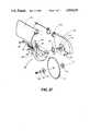
- FIG. 6is an enlarged fragmentary side elevational view illustrating removal of the lower swinging blade guard for access to the shaft of the compound miter saw blade;
- FIG. 7is a top plan view of the compound miter saw similar to the top plan view of FIG. 3, but illustrating the work supporting fence in a rear fence position;
- FIG. 8is an enlarged fragmentary side elevational view, partly in section illustrating the manner in which the work supporting fence is clamped relative to the supporting frame, in either front or rear work supporting fence positions;
- FIG. 9is a right side elevational view, partly in section, of the compound miter saw of the present invention.
- FIG. 10is a bottom perspective view of the compound miter saw of the present invention.
- FIG. 11is an exploded perspective view of the turntable and related components associated with the compound miter saw of the present invention.
- FIG. 12is an exploded perspective view of the miter saw blade and upper and lower blade guards associated therewith in the compound miter saw of the present invention.
- the compound miter saw 1includes a supporting base or frame 3 having an arcuate miter scale 5 attached at an upper, front position thereof for ease of use and visibility by the user.
- a turntable 7is selectively rotatably mounted within the supporting frame or base 3 and is provided with a saw blade slot 9 therein.
- a miter lock handle 11is constructed to selectively rotate the turntable 7 relative to the supporting frame 3 in order to position the turntable 7 in the desired bevel setting, as shown on the bevel scale 5.
- a work supporting fence 13is provided.
- the work supporting fence 13has fence lock handles 15 enabling the work supporting fence to be mounted in front and rear positions to accommodate work pieces of different size, for example, 2 ⁇ 4's in the front fence position and 2 ⁇ 6's in the rear fence position.
- a miter saw blade 17is rotatably mounted within the upper blade guard and housing 19 and is power driven by an electric motor 21 mounted to the upper blade guard and housing 19. Suitable power is available to the electric motor 21 via the power cord 23.
- the upper blade guard and housing 19is pivotally mounted relative to the supporting frame or base 3 at 25, through uniquely designed closed cylinders as will be discussed hereinafter.
- FIG. 3 of the drawingsThe miter cutting of workpieces, by moving the turntable 7 via the miter lock handle 11, is best illustrated in FIG. 3 of the drawings.
- FIG. 4 of the drawingsalso shows how the compound miter saw 1 can be utilized to make bevel cuts in workpieces.
- the bevel adjustment for the compound miter sawincludes a bevel lock handle 27 which may be loosened to allow the entire upper blade guard and housing 19, including components associated therewith, to be pivotally moved along pivot axis 29, to the desired bevel angle, as determined by the bevel scale 31 and fixed pointer 33 on adjacent fixed and moving cylinders, as will be described.
- a miter saw handle 35 with associated trigger switch 37 that energizes the motor 21is provided for raising and lowering the miter saw blade 17 about the pivot axis 25, a miter saw handle 35 with associated trigger switch 37 that energizes the motor 21 is provided. As is well known, a suitable lock-button 39 may be provided to prevent actuation of the trigger switch 37, if desired.
- a swinging lower blade guard 41is provided in order to provide added protection to the user from the miter saw blade 17 when the compound miter saw is at an upper at rest position, as seen in FIGS. 1-2 of the drawings.
- the swinging lower blade guard 41is preferably made from transparent plastic material to facilitate visibility of the miter saw blade 17 by the user. As will be described hereinafter, the construction of the swinging lower blade guard 41 relative to the upper blade guard and housing 19 facilitates access to the shaft of the miter saw blade 17, to facilitate changing of the blades, as may be desired, and does not interfere with bevel cuts.
- a dust bag 43is attached to an exhaust outlet 45 at the rear of the upper blade guard housing 19.
- the swinging lower blade guardis partially disconnected, and a handle latch 47, when in the dotted line position shown in FIG. 2 of the drawings, holds the upper blade guard and housing 19 in a lower position for shipment.
- the handle latch 47When moved its full line position as shown in FIG. 2 of the drawings, the handle latch 47 becomes inoperative, allowing the upper blade guard and housing 19 to be pivotally mounted about the pivot axis 25 for normal operation of the compound miter saw.
- the supporting frame or base 3is a one-piece cast iron section having spaced pairs of depending legs 49, 49 which support the frame 3 on a horizontal surface. If desired, the supporting frame 3 may be attached to a plywood mounting board, and for this purpose, suitable mounting bolts (not shown) are positioned through the mounting bolt apertures 51 in order to mount and secure the supporting frame 3 to a plywood mounting board or the like.
- the supporting frame 3includes an integral upstanding circular-shaped wall 53, and a webbed bottom wall 55 having a through opening 57 centrally positioned relative to the upstanding annular or circular-shaped upstanding wall 53.
- a turntable 7is designed to be received by the supporting frame 3, and as can be seen, the turntable 7 is complementary shaped for receipt within the upstanding annular or circular wall 53 of the supporting frame 3.
- the turntable 7is provided with a complementary shaped circumferentially extending depending flange 59 (see FIGS. 9-10) which is rotatably received within the centrally positioned through opening 57 of the supporting frame 3.
- the turntable 7 and associated saw blade slot 9are capable of being rotatably positioned relative to the supporting frame 3 and miter scale 5.
- a miter lock handle 11For moving the turntable 7, a miter lock handle 11 is provided.
- a handle extension 61having a generally vertically extending section 63 is provided with a threaded opening for receiving the miter lock handle 11.
- Within the handle extension 61are spaced bolt receiving apertures 65 for receiving the bolt and other components 67 as shown in FIG. 11 of the drawings.
- the bolts 67are received within internal bosses 69 of the webbed bottom wall 55 of the supporting frame 3, as best seen in FIGS. 9-10 of the drawings.
- An index spring 71which is generally complementary shape relative to the handle extension 61 is superimposed above the handle extension 61 and is captured between the handle extension 61 and the under surface of the webbed bottom wall 55 of the supporting frame 3.
- the index spring 71At one end of the index spring 71 is a generally vertically extending section 73 which corresponds to the generally vertically extending portion 63 of the handle extension 61.
- a finger engaging section 74extends generally horizontally and laterally outwardly from the generally vertically extending section 73, for purposes soon to be described.
- the index springis provided with spaced apertures 75 which are correspondingly spaced the same distance as the bolt apertures 65 for receiving bolt 67 therein as a result, the index spring 71 is mounted between the handle extension 61 and the outside surface of the webbed bottom wall 55.
- the index spring 71is angularly and upwardly offset at 77 from the handle extension 61 so as to peripherally engage an undersurface of the webbed bottom wall 55 as best seen in FIGS. 1, 5 and 9 of the drawings.
- the index spring 71is normally biased at 77 into contact with the supporting frame 3 along a peripheral undersurface of the webbed bottom wall 55.
- the spring release latch 74is provided, enabling the user to depress the spring latch to lower the section 77 out of peripheral engagement with the under surface of the webbed bottom wall 55.
- the miter lock handle 11is threadably rotated into engagement with depending flat spring 79, attached by the fastener components 81 to the generally vertically extending section 63 of the handle extension 61.
- the depending flat spring 79When the depending flat spring 79 is engaged by the rounded end, adjacent the threaded section of the miter lock handle 11, the depending flat spring 79 is trapped between the miter lock handle 11 and the outer peripheral surface of the upstanding annular or circular wall 53 of the supporting frame, to apply a resilient biasing force relative to the miter lock handle 11 so as to resist unauthorized loosening or retrograde movement thereof.
- the fastener components 81also clamp a flat washer 83 to the upstanding section 63 of the handle extension 61, the flat washer 83 carrying a pointer thereon for accurate alignment and positioning of the turntable 7 and associated miter lock handle 11 relative to the miter scale 5 of the supporting frame 3, as will be appreciated.
- a depending arm 85is attached to the work supporting fence 13 by suitable fasteners 87 at one end.
- the depending arm 85angularly extends downwardly therefrom and terminates at the other end in a generally vertically extending annular boss 89 which is received within the elongated slot 91 of the index spring 71, as best seen in FIGS. 9 and 11.
- the annular boss 89 of the depending arm 85is slidably received within the elongated slot 91 to maintain the work supporting fence 13 in an accurately fixed position relative to various miter positions of the turntable 7.
- the elongated slot 9 of the turntable 7opens up into a fanned-shaped or other configured opening 93 for purposes now to be described.
- the elongated slot 9is maintained in alignment with the miter saw blade 17, as discussed above.
- the work supporting fence 13moves as the turntable 7 and saw blade 17 mounted thereon rotates, the saw blade 17 will be maintained in alignment relative to the saw blade slot 9 and fence 13.
- the work supporting fence 13is formed into a spaced pair of work engaging elements 95, 97 which are longitudinally aligned relative to one another across the saw blade slot 9.
- an arcuately-shaped intermediate element 99Connecting the aligned pair of work engaging elements 95, 97 is an arcuately-shaped intermediate element 99 also having a fan-shaped opening 101 which is complementary to and generally vertically aligned with the fan-shaped opening 93 associated with the saw blade slot 9 of the turntable 7.
- the miter saw blade 17 in the area of the work supporting fence 13is received within the fan-shaped aligned openings 93, 99 of the turntable and work supporting fence 7, 13 respectively, so as to avoid any interference therewith.
- the depending arm 85 of the work supporting fence 13is attached to an undersurface of the intermediate arcuately shaped element 99, and the annular boss 89 at its lower end is slidably received within the elongated slot 91, in order to allow the work supporting fence 13 to move as the turntable 7 and miter saw blade 17 are rotated to the miter adjustment desired.
- each of the work engaging elements 95, 97are provided with angularly offset surfaces 103 for the work engaging element 95 and angularly offset surface 105 for the work engaging element 97.
- Each of the angularly offset surfaces 103, 105are preferably offset 30° from the bottom surface of the work supporting fence 13, which rests upon the upper or top surface of the supporting frame 3.
- An elongated slot 107is provided in the angularly offset surface 103 and a elongated slot 109 is provided in the angularly offset surface 105 for receiving the side fence lock handle 15, 15.
- the elongated slots 107 and 109take up front and back play of the fence 13, while allowing handle clearance.
- Each of the work supporting fence lock handles 15has a pivoting finger gripping rod section 111 having an outer knurled surface and a threaded section 113, with an intermediate head or clamping area 116 therebetween.
- the work supporting fence 13has both rear and front positions.
- the supporting frame 3as viewed along line 8--8 of FIG. 7, is provided with front and rear threaded opening 115, 117 which are complementary threaded relative to the threaded male stud 113 of each of the work supporting fence lock handles 15.
- each of the front and rear threaded openings 115, 117 in the supporting frame 3are angularly offset, also preferably at 30° from the top or upper surface of the supporting frame 3.
- the head or clamping area 116 of the work supporting fence lock handles 15will engage the angularly offset surface 103 or 105 and thus apply clamping pressure through the angularly offset surfaces 103, 105, as the work supporting fence lock handles 15 take up slack in the elongated slots 107, 109 and clamp the work supporting fence 15 relative to the supporting frame 3.
- FIG. 3 of the drawingsThe front position of the work supporting fence is shown in FIG. 3 of the drawings where a 2 ⁇ 4 is engaged by the work supporting fence 13 and the compound miter saw 1.
- the front fence positionthe plane of the work supporting fence 13 and element 89 are located approximately at the center of the turntable 7 and the fence is fixed in place.
- the rear fence positionis shown in FIG. 7 of the drawings, where the work supporting fence 13 has been moved rearward to accommodate a 2 ⁇ 6 for cutting thereof
- the fence 13is offset from the center of the turntable 7.
- the rear fence positionis designed to slide side-to-side, with the work supporting fence lock handles 15 loosened, when the miter setting is changed. This feature lets the work supporting fence 13 move to provide maximum support for the workpiece.
- the work supporting fence lock handles 15are tightened to again clamp the work supporting fence 13 relative to the supporting frame 3.
- Still another improvement of the present invention in the compound miter saw 1relates to the pivotal mounting of the compound miter saw 1 on the turntable 7 and the combined bevel adjustment construction associated therewith, as best seen in FIGS. 1-5 and 9 of the drawings.
- the upper blade guard and housing 19carry the motor 21, saw blade 17, swingable blade guard 41 and related components are pivotally mounted along pivot axis 25, while the upper blade guard and housing 19, miter saw blade 17 and related components are pivotally moved about pivot axis 29 for bevel adjustment of the compound miter saw.
- the pivot axis 25comprises a pivot bolt 25 which extends through a cylindrically shaped section 121 for the upper blade guard and arm or housing 19 and is complementary shaped relative to an interfitting and mirror image cylindrical section 123. Between these two cylindrical sections 121, 123 which is confined a torsional spring 125 for normally urging the upper blade guard 19 and miter saw blade 17 in the upper at rest position.
- a torsional spring 125for normally urging the upper blade guard 19 and miter saw blade 17 in the upper at rest position.
- Integrally attached to the cylindrically shaped section 123is a transversely extending cylindrically shaped section 127 that extends therebelow.
- the cylindrically shaped section 127is attached via the pivot bolt 29 to a smaller, but complementary shaped cylindrical section 129, the later being fixedly mounted to the turntable 7.
- the smaller, but complementary shaped cylindrical section 129is provided with a radially outwardly extending flange section 131 which is clamped to the turntable 7 by the clamping bolts 133.
- a bevel lock handle 27extends through the cylindrical section 127 and engages the corresponding cylindrical section 129 to limit relative rotational movement thereof along the pivot bolt axis 29.
- the cylindrical section 127containing the bevel scale 131, may be rotated relative to the corresponding cylindrical section 129, fixedly mounted to the turntable 7, enabling the upper blade guard and housing 19, miter saw blade 17 and related components to assume a different compound or bevel adjustment, as may be desired.
- the fixed cylinder section 123 of the first closed cylindercomprising the cylindrical sections 121 and 123 containing the torsional spring 125, during pivotal movement of the saw between operational and at rest positions, is integrally joined to the moving cylinder section 127 of the second closed cylinder comprising the cylinder sections 127, 129, during bevel pivotal adjustment of the saw relative to the turntable 7.
- the closed cylinder construction, of the first and second cylinders described aboveunique, but the construction is substantially more durable and rigid than other prior designs.
- the bevel scale 131is more accurate by virtue of being mounted on a controlled radius of a cylinder 127.
- the swinging blade guard assembly 41is designed to permit quick and easy removal from the miter saw blade 17 and upper blade guard and housing 19, to facilitate access to the saw blade shaft or arbor screw, 135, shown in FIG. 12 of the drawings, for removing and changing the miter saw blade 17.
- the arbor screw 135is first mounted through an arbor washer 137, then through an outer blade collar 139, and finally to a threaded opening (not shown) within an extended motor shaft (not shown) for rotating the miter saw blade 17 through the electric motor 21.
- the pivot center for the swinging blade guard assembly 41, relative to the upper blade guard and housing 19,is eccentrically offset upwards from the saw blade shaft (or arbor screw 135) as well as being eccentrically offset back towards the pivotal mounting of the upper blade guard and housing 19, through the pivot bolt axis 25.
- the swinging blade guard assembly 41includes a channel-shaped swinging blade guard 143 preferably formed of transparent plastic material.
- the swinging blade guard 143has an integral hub section 145, covered by a plate or cover 147 on one side thereof and a spring 149 on the other captured between the integral hub 145 and a mounting plate 151.
- the mounting plate 151is attached to the upper blade guard and housing 19. An assembly of these components together is best seen in FIG. 1 of the drawings.
- a threaded fastener 153having a washer and bushing components associated therewith, extends through the upper blade guard and housing 19, through an aperture 155 in the mounting plate 151 through an aperture 157 in the integral annular boss 145, through an aperture (not shown) in the cover or plate 147, and finally into threaded engagement with the complementary nut 159, having a washer associated therewith.
- the upper blade guard 143as best seen in FIG. 1 and 5 of the drawings has its pivot center along the fastener 153, which is both eccentric upwardly offset and is eccentrically offset also back towards the pivotal mounting 25 of the upper blade guard and housing 19.
- the swinging blade guard assembly 41further includes an actuator arm 161 having one end 163 attached to the cylindrical section 123, and the other end 165 having an elongated slot 167 permitting slideable movement of the fixed pin 169, which is eccentrically mounted to the plate or cover 147. From an at rest position, the swinging blade cover 143 is moved upwardly as the eccentrically mounted slideable pin 169 moves within the elongated slot 167 of the actuator 161. Torsional force of the spring 149, together with the aforementioned eccentric mounting and construction of the components, affords the upward movement of the swinging blade guard 143, as the upper blade guard and housing 19 together with miter saw blade 17, is lowered from an at rest to an operational position.
- the swinging blade guard 143is eccentrically mounted upwards from the arbor screw 135, as well as being eccentrically offset back towards the pivotal mounting 25 for the upper blade guard and housing 19 and miter saw blade 17.
- the swinging blade guard 143includes an actuator arm 161, which is eccentrically offset from the pivot center 153-159 of the swinging blade guard, as the result of the eccentrically mounted pin 169 being attached to the plate or cover 147, and being slideably received within the elongated slot 167 of the actuator 161.
- FIG. 6 of the drawingsfor a description of the manner in which the components of the swinging blade guard assembly 41 are quickly and easily moved out of the way to facilitate access to the arbor screw 135, for changing the miter saw blade 17.
- the threaded fastener 171assists in securing the mounting plate 151 to the upper blade guard and housing 19, but may be loosened to enable the mounting plate 151 to be rotated or pivoted about the rivet or other fastener 173 securing the mounting plate 151 to the upper blade guard or housing 19.
- the eccentrically offset pin 169attached to the cover or plate 147, slideably moves within the elongated slot 167 of the actuator arm towards the pivotal mounting of the upper blade guard and housing 19, as shown in FIG. 6.
- the swinging blade guard 143will then be positioned above the upper blade guard and housing 19, leaving both hands free, and enabling quick and open access to the arbor screw 135, for removing or changing the blade 17.
- the present inventiondiscloses several improvements in a compound miter saw including alignment of a rotating turntable and associated saw blade slot relative to a movable work supporting fence, the accurate and reliable mounting of the work supporting fence relative to the supporting frame, the combined pivoting movement and bevel adjustment made possible by the closed cylinder constructions, and the ability to move a swinging blade guard quickly and easily out of the way from an upper blade guard and housing to facilitate access to the blade shaft or arbor screw for removing or changing the blade.
Landscapes
- Engineering & Computer Science (AREA)
- Mechanical Engineering (AREA)
- Life Sciences & Earth Sciences (AREA)
- Wood Science & Technology (AREA)
- Forests & Forestry (AREA)
- Sawing (AREA)
Abstract
Description
Claims (28)
Priority Applications (3)
| Application Number | Priority Date | Filing Date | Title |
|---|---|---|---|
| US07213277US4934233B1 (en) | 1988-06-29 | 1988-06-29 | Compound miter saw |
| CA000585345ACA1286953C (en) | 1988-06-29 | 1988-12-08 | Compound miter saw |
| US07519873US5042348B1 (en) | 1988-06-29 | 1990-05-07 | Compound miter saw |
Applications Claiming Priority (1)
| Application Number | Priority Date | Filing Date | Title |
|---|---|---|---|
| US07213277US4934233B1 (en) | 1988-06-29 | 1988-06-29 | Compound miter saw |
Related Child Applications (1)
| Application Number | Title | Priority Date | Filing Date |
|---|---|---|---|
| US07519873ContinuationUS5042348B1 (en) | 1988-06-29 | 1990-05-07 | Compound miter saw |
Publications (2)
| Publication Number | Publication Date |
|---|---|
| US4934233Atrue US4934233A (en) | 1990-06-19 |
| US4934233B1 US4934233B1 (en) | 1994-08-23 |
Family
ID=22794449
Family Applications (2)
| Application Number | Title | Priority Date | Filing Date |
|---|---|---|---|
| US07213277Expired - LifetimeUS4934233B1 (en) | 1988-06-29 | 1988-06-29 | Compound miter saw |
| US07519873Expired - LifetimeUS5042348B1 (en) | 1988-06-29 | 1990-05-07 | Compound miter saw |
Family Applications After (1)
| Application Number | Title | Priority Date | Filing Date |
|---|---|---|---|
| US07519873Expired - LifetimeUS5042348B1 (en) | 1988-06-29 | 1990-05-07 | Compound miter saw |
Country Status (2)
| Country | Link |
|---|---|
| US (2) | US4934233B1 (en) |
| CA (1) | CA1286953C (en) |
Cited By (165)
| Publication number | Priority date | Publication date | Assignee | Title |
|---|---|---|---|---|
| US5063805A (en)* | 1989-11-08 | 1991-11-12 | Emerson Electric Co. | Compound miter saw |
| US5063802A (en)* | 1989-11-16 | 1991-11-12 | Ryobi Ltd. | Variable cutting-angle circular saw device |
| DE4033037A1 (en)* | 1990-10-18 | 1992-04-23 | Lutz Eugen Masch | Miter saw |
| DE4033785A1 (en)* | 1990-10-24 | 1992-04-30 | Lutz Eugen Masch | Mitring saw unit - has rotary saw blade located on pivot arm beneath rotatable workpiece table |
| US5146825A (en)* | 1990-07-31 | 1992-09-15 | Ryobi Ltd. | Motor-driven chop saw having improved lower blade guard arrangement |
| US5146826A (en)* | 1990-01-13 | 1992-09-15 | Ryobi Ltd. | Circular saw device having variable cut-off angle |
| US5181448A (en)* | 1991-12-20 | 1993-01-26 | Emerson Electric Co. | Miter saw apparatus with adjustable workpiece supporting fence |
| US5183235A (en)* | 1989-05-09 | 1993-02-02 | Safe-T-Jack, Inc. | Apparatus for aligning and releasing a two-part jack system |
| US5199343A (en)* | 1991-10-09 | 1993-04-06 | Black & Decker Inc. | Power saw with louvered blade guard |
| US5207141A (en)* | 1991-01-30 | 1993-05-04 | Ryobi Limited | Turntable positioning device of desk type cutting machine |
| US5216964A (en)* | 1991-02-05 | 1993-06-08 | Ryobi Limited | Angle adjusting device for circular saw with table |
| US5235889A (en)* | 1992-03-25 | 1993-08-17 | Delta International Machinery Corp. | Compound miter saw |
| US5265511A (en)* | 1992-08-13 | 1993-11-30 | Milwaukee Electric Tool Corporation | Controlled axial position hinge assembly |
| US5285708A (en)* | 1992-05-18 | 1994-02-15 | Porter-Cable Corporation | Miter saw alignment system |
| US5297463A (en)* | 1991-10-09 | 1994-03-29 | Black & Decker Inc. | Adjustable fence for compound miter saw |
| USD345743S (en) | 1992-03-25 | 1994-04-05 | Delta International Machinery Corp. | Motorized miter box |
| EP0601805A1 (en)* | 1992-12-04 | 1994-06-15 | Black & Decker Inc. | An angularly adjustable pivoted circular saw with saw dust removal means |
| USD348272S (en) | 1992-03-25 | 1994-06-28 | Delta International Machinery Corp. | Compound miter saw |
| USD352509S (en) | 1993-05-06 | 1994-11-15 | Porter-Cable Corporation | Miter saw |
| US5370025A (en)* | 1992-08-13 | 1994-12-06 | Milwaukee Electric Tool Corporation | Motorized saw with movable blade guard actuating linkage |
| US5375495A (en)* | 1992-05-18 | 1994-12-27 | Porter-Cable Corporation | Optical alignment system for circular power saws |
| EP0638399A1 (en)* | 1993-08-12 | 1995-02-15 | Black & Decker Inc. | A power saw fence guide |
| EP0642896A1 (en)* | 1993-08-12 | 1995-03-15 | Black & Decker Inc. | Pivot bearing for a chop saw |
| EP0642897A1 (en)* | 1993-08-12 | 1995-03-15 | Black & Decker Inc. | A bevel saw angle indicator |
| US5421228A (en)* | 1990-06-29 | 1995-06-06 | Ryobi Limited | Desk-top slide type circular power saw |
| US5425294A (en)* | 1993-06-03 | 1995-06-20 | Hitachi Koki Haramachi Co., Ltd. | Desk-top cutting machine with tiltable saw |
| USD372484S (en) | 1995-09-13 | 1996-08-06 | Black & Decker Inc. | Chop saw design |
| USD374803S (en) | 1995-06-09 | 1996-10-22 | Emerson Electric Co. | Compound miter saw |
| USD376806S (en) | 1994-07-20 | 1996-12-24 | Milwaukee Electric Tool Corporation | Compound miter saw |
| US5623860A (en)* | 1994-12-15 | 1997-04-29 | Emerson Electric Co. | Adjustable/bypassable bevel stop for compound miter saw |
| CN1036054C (en)* | 1992-10-19 | 1997-10-08 | 埃莫森电器公司 | Swinging blade guard assembly |
| US5720096A (en)* | 1993-04-26 | 1998-02-24 | Black & Decker Inc. | Power tool with locking fence |
| US5755148A (en)* | 1995-07-07 | 1998-05-26 | Black & Decker Inc. | Adjustable fence for a compound miter saw |
| US5778747A (en)* | 1996-11-21 | 1998-07-14 | Rexon Industrial Corp., Ltd. | Power saw having an ergonomically-designed handle and safety switch |
| USD399218S (en) | 1997-06-19 | 1998-10-06 | Black & Decker Inc. | Base assembly for a sliding compound miter saw |
| US5819619A (en)* | 1991-10-09 | 1998-10-13 | Black & Decker Inc. | Dust collection system for compound miter saw |
| US5829333A (en)* | 1994-07-08 | 1998-11-03 | Milwaukee Electric Tool Corporation | Bevel angle adjustment mechanism for a compound miter saw |
| US5855366A (en)* | 1997-10-29 | 1999-01-05 | P & F Brother Industrial Corporation | Work supporting device mountable on a worktable of a circular sawing apparatus |
| US5865079A (en)* | 1994-07-08 | 1999-02-02 | Milwaukee Electric Tool Corporation | Adjustable workpiece support apparatus for a compound miter saw |
| US5870938A (en)* | 1995-12-12 | 1999-02-16 | Black & Decker Inc. | Bevel locking system for a sliding compound miter saw |
| US5937720A (en)* | 1995-08-10 | 1999-08-17 | Milwaukee Electric Tool Corporation | Lower blade guard actuating mechanism for a slide compound miter saw |
| US5957021A (en)* | 1995-10-10 | 1999-09-28 | Black & Decker, Inc. | Guard and control apparatuses for sliding compound miter saw |
| USD415001S (en)* | 1999-02-01 | 1999-10-12 | Black & Decker Inc. | Chop saw |
| US5996460A (en)* | 1992-03-13 | 1999-12-07 | Waite; Lance H. | Cut line indicator for power cutting material |
| USD418149S (en)* | 1998-05-11 | 1999-12-28 | Black & Decker Inc. | Base assembly for a sliding compound miter saw |
| US6009782A (en)* | 1997-06-19 | 2000-01-04 | Makita Corporation | Table saw |
| US6032563A (en)* | 1996-12-05 | 2000-03-07 | Black & Decker Inc. | Bevel locking system for a sliding compound miter saw |
| US6032562A (en)* | 1995-12-12 | 2000-03-07 | Black & Decker Inc. | Bevel locking system for a sliding compound miter saw |
| US6067885A (en)* | 1995-12-12 | 2000-05-30 | Black & Decker Inc. | Bevel locking system for a sliding compound miter saw |
| US6182548B1 (en)* | 1995-10-10 | 2001-02-06 | Black & Decker Inc. | Guard and control apparatuses for sliding compound miter saw |
| US6272960B1 (en) | 1998-06-03 | 2001-08-14 | Black & Decker Inc. | Chop saw |
| US6279442B1 (en)* | 1998-09-11 | 2001-08-28 | Chin-Chin Chang | Blade guard device for a sawing machine |
| US20020066346A1 (en)* | 2000-09-29 | 2002-06-06 | Gass Stephen F. | Miter saw with improved safety system |
| US6427570B1 (en) | 1991-10-09 | 2002-08-06 | Black & Decker Inc. | Dust collection system for compound miter saw |
| US6431042B1 (en) | 1994-05-13 | 2002-08-13 | Milwaukee Electric Tool Corporation | Turntable mechanism for a cutting tool |
| US6470778B1 (en) | 1998-05-20 | 2002-10-29 | Black & Decker Inc. | Dust collector for a power tool |
| US6474206B1 (en) | 1995-12-12 | 2002-11-05 | Black & Decker Inc. | Miter saw with wear plates and orientation system therefor |
| US6478664B2 (en) | 2001-03-12 | 2002-11-12 | One World Technologies, Inc. | Cut-off saw |
| US20020166433A1 (en)* | 2001-05-10 | 2002-11-14 | Ceroll Warren A. | Miter detent overide for a sliding compound miter saw |
| EP1208952A3 (en)* | 1996-10-31 | 2002-12-04 | Black & Decker Inc. | Guard and control apparatuses for sliding compound mitre saw |
| US6513412B2 (en) | 2001-01-09 | 2003-02-04 | Porter Cable Corp. | Adjustment mechanism |
| EP1287954A1 (en)* | 2001-08-10 | 2003-03-05 | Techtronic Industries Co., Ltd. | Bevel adjustment mechanism for a compound miter saw |
| US20030140759A1 (en)* | 1998-03-11 | 2003-07-31 | Daryl Meredith | Sliding saw |
| US20030150311A1 (en)* | 2002-02-11 | 2003-08-14 | Carroll Craig Allen | Remotely actuated beveling systems for a miter saw |
| US6615701B2 (en) | 2001-08-01 | 2003-09-09 | Delta International Machinery Corp. | Bevel stop for cutting device |
| US6631661B2 (en)* | 1995-12-12 | 2003-10-14 | Black & Decker Inc. | Bevel locking system for a sliding compound miter saw |
| USD481401S1 (en) | 2002-11-05 | 2003-10-28 | Emerson Electric Co. | Compound miter saw |
| US20030202091A1 (en)* | 2002-04-18 | 2003-10-30 | Jaime Garcia | Modular assisted visualization system |
| US6658976B2 (en)* | 2001-01-29 | 2003-12-09 | One World Technologiess, Inc. | Ergonomic miter saw handle |
| US20030233921A1 (en)* | 2002-06-19 | 2003-12-25 | Garcia Jaime E. | Cutter with optical alignment system |
| US20040074362A1 (en)* | 2002-10-16 | 2004-04-22 | S-B Power Tool Corporation | Front-accessible bevel locking system |
| US20040154448A1 (en)* | 2002-04-30 | 2004-08-12 | Credo Technology Corporation | Fine-adjustment mechanism to preset a miter saw for precision miter cuts |
| US20040173430A1 (en)* | 2003-03-05 | 2004-09-09 | Gass Stephen F. | Retraction system and motor position for use with safety systems for power equipment |
| US20040255748A1 (en)* | 2001-01-29 | 2004-12-23 | Dils Jeffrey M. | Ergonomic miter saw handle |
| EP1470883A3 (en)* | 2001-05-18 | 2005-03-09 | Techtronic Industries Co., Ltd. | Miter saw having a light beam alignment system |
| US6880440B2 (en) | 2000-09-29 | 2005-04-19 | Sd3, Llc | Miter saw with improved safety system |
| US6899005B1 (en)* | 1991-10-09 | 2005-05-31 | Black & Decker Inc. | Adjustable fence for compound miter saw |
| US6920814B2 (en) | 2000-08-14 | 2005-07-26 | Sd3, Llc | Cutting tool safety system |
| US20050160895A1 (en)* | 2002-10-31 | 2005-07-28 | Garcia Jaime E. | Dual bevel table saw |
| US20050178259A1 (en)* | 2001-08-13 | 2005-08-18 | Gass Stephen F. | Miter saw with improved safety system |
| US6937336B2 (en) | 2002-08-15 | 2005-08-30 | Black & Decker, Inc. | Optical alignment system for power tool |
| US20050188806A1 (en)* | 2002-10-31 | 2005-09-01 | Garcia Jaime E. | Riving knife assembly for a dual bevel table saw |
| US6945149B2 (en) | 2001-07-25 | 2005-09-20 | Sd3, Llc | Actuators for use in fast-acting safety systems |
| US6945148B2 (en) | 2000-09-29 | 2005-09-20 | Sd3, Llc | Miter saw with improved safety system |
| US6957601B2 (en) | 2000-08-14 | 2005-10-25 | Sd3, Llc | Translation stop for use in power equipment |
| US20050247178A1 (en)* | 2004-04-15 | 2005-11-10 | Hetcher Jason D | Power tool having an elastomeric material |
| US6971297B1 (en) | 1995-10-10 | 2005-12-06 | Black & Decker Inc. | Guard and control apparatuses for sliding compound miter saw |
| US20050270531A1 (en)* | 2004-06-02 | 2005-12-08 | Garcia Jaime E | Optical alignment system for power tools |
| US20060011034A1 (en)* | 2004-07-13 | 2006-01-19 | Gehret Robert S | Riving knife assembly for table saws |
| US6994004B2 (en) | 2000-09-29 | 2006-02-07 | Sd3, Llc | Table saw with improved safety system |
| US6997090B2 (en) | 2001-08-13 | 2006-02-14 | Sd3, Llc | Safety systems for power equipment |
| US7000514B2 (en) | 2001-07-27 | 2006-02-21 | Sd3, Llc | Safety systems for band saws |
| US7024975B2 (en) | 2000-08-14 | 2006-04-11 | Sd3, Llc | Brake mechanism for power equipment |
| US20060076385A1 (en)* | 2002-04-18 | 2006-04-13 | Etter Mark A | Power tool control system |
| US20060075867A1 (en)* | 2002-11-27 | 2006-04-13 | Etter Mark A | Laser apparatus |
| US20060096425A1 (en)* | 2003-04-29 | 2006-05-11 | Keller David V | System and method for rapidly stopping a spinning table saw blade |
| US20060106482A1 (en)* | 2002-04-18 | 2006-05-18 | Etter Mark A | Power tool control system |
| US20060104731A1 (en)* | 2002-04-18 | 2006-05-18 | Etter Mark A | Drill press |
| US20060101958A1 (en)* | 2003-07-31 | 2006-05-18 | Garcia Jaime E | Table saw |
| US20060101961A1 (en)* | 2002-04-18 | 2006-05-18 | Etter Mark A | Power tool control system |
| US20060111809A1 (en)* | 2002-04-18 | 2006-05-25 | Etter Mark A | Graphical user interface |
| US20060112804A1 (en)* | 2001-01-29 | 2006-06-01 | Dils Jeffrey M | Ergonomic miter saw handle |
| US20060116787A1 (en)* | 2002-04-18 | 2006-06-01 | Etter Mark A | Power tool control system |
| US7055417B1 (en) | 1999-10-01 | 2006-06-06 | Sd3, Llc | Safety system for power equipment |
| US7073268B1 (en) | 2002-04-18 | 2006-07-11 | Black & Decker Inc. | Level apparatus |
| US7077039B2 (en) | 2001-11-13 | 2006-07-18 | Sd3, Llc | Detection system for power equipment |
| US7100483B2 (en) | 2000-08-14 | 2006-09-05 | Sd3, Llc | Firing subsystem for use in a fast-acting safety system |
| US7137326B2 (en) | 2000-08-14 | 2006-11-21 | Sd3, Llc | Translation stop for use in power equipment |
| US7171879B2 (en) | 2001-07-02 | 2007-02-06 | Sd3, Llc | Discrete proximity detection system |
| US20070034064A1 (en)* | 2005-08-12 | 2007-02-15 | Tomomasa Nishikawa | Dust-collecting unit and electric tool having the same |
| US7197969B2 (en) | 2001-09-24 | 2007-04-03 | Sd3, Llc | Logic control with test mode for fast-acting safety system |
| US7210383B2 (en) | 2000-08-14 | 2007-05-01 | Sd3, Llc | Detection system for power equipment |
| US7225712B2 (en) | 2000-08-14 | 2007-06-05 | Sd3, Llc | Motion detecting system for use in a safety system for power equipment |
| US7228772B2 (en) | 2000-08-14 | 2007-06-12 | Sd3, Llc | Brake positioning system |
| US7231856B2 (en) | 2001-06-13 | 2007-06-19 | Sd3, Llc | Apparatus and method for detecting dangerous conditions in power equipment |
| US7243440B2 (en) | 2004-10-06 | 2007-07-17 | Black & Decker Inc. | Gauge for use with power tools |
| US7284467B2 (en) | 2000-08-14 | 2007-10-23 | Sd3, Llc | Apparatus and method for detecting dangerous conditions in power equipment |
| US7290472B2 (en) | 2002-01-14 | 2007-11-06 | Sd3, Llc | Miter saw with improved safety system |
| US20070277660A1 (en)* | 2006-06-02 | 2007-12-06 | Neil Walmsley | Plunge-cut circular saw |
| US7308843B2 (en) | 2000-08-14 | 2007-12-18 | Sd3, Llc | Spring-biased brake mechanism for power equipment |
| US20080041209A1 (en)* | 2006-08-18 | 2008-02-21 | Ming Li | Power saw |
| US20080060495A1 (en)* | 2002-06-25 | 2008-03-13 | Jaime Garcia | Front Bevel Indicator/Front Bevel Lock |
| US7350445B2 (en) | 2003-08-20 | 2008-04-01 | Sd3, Llc | Brake cartridge for power equipment |
| US7350444B2 (en) | 2000-08-14 | 2008-04-01 | Sd3, Llc | Table saw with improved safety system |
| US7357056B2 (en) | 2000-09-29 | 2008-04-15 | Sd3, Llc | Cutting tool safety system |
| US7359174B2 (en) | 2000-08-14 | 2008-04-15 | Sd3, Llc | Motion detecting system for use in a safety system for power equipment |
| US7377199B2 (en) | 2000-09-29 | 2008-05-27 | Sd3, Llc | Contact detection system for power equipment |
| US20080211154A1 (en)* | 2005-08-05 | 2008-09-04 | Gmca Pty, Ltd. | Apparatus Including Spring and Method For Tensioning the Same |
| US20080282858A1 (en)* | 2000-08-14 | 2008-11-20 | Gass Stephen F | Miter saw with improved safety system |
| US7472634B2 (en) | 2003-08-20 | 2009-01-06 | Sd3, Llc | Woodworking machines with overmolded arbors |
| US7481140B2 (en) | 2005-04-15 | 2009-01-27 | Sd3, Llc | Detection systems for power equipment |
| US7509899B2 (en) | 2000-08-14 | 2009-03-31 | Sd3, Llc | Retraction system for use in power equipment |
| US20090095141A1 (en)* | 2007-10-15 | 2009-04-16 | Black & Decker Inc. | Adjustable fence for a miter saw |
| US7536238B2 (en) | 2003-12-31 | 2009-05-19 | Sd3, Llc | Detection systems for power equipment |
| US20090139382A1 (en)* | 2007-12-04 | 2009-06-04 | Clack James B | Portable miter saw |
| US20090188659A1 (en)* | 2008-01-27 | 2009-07-30 | International Business Machines Corporation | System and method for implementing a front door air to water heat exchanger |
| US20090199689A1 (en)* | 2004-04-15 | 2009-08-13 | Hetcher Jason D | Miter adjustment assembly for a saw |
| US7600455B2 (en) | 2000-08-14 | 2009-10-13 | Sd3, Llc | Logic control for fast-acting safety system |
| US7610836B2 (en) | 2000-08-14 | 2009-11-03 | Sd3, Llc | Replaceable brake mechanism for power equipment |
| US7621205B2 (en) | 1999-10-01 | 2009-11-24 | Sd3, Llc | Band saw with safety system |
| US20100058909A1 (en)* | 2008-09-11 | 2010-03-11 | Shaodong Chen | Power tool |
| US7707920B2 (en) | 2003-12-31 | 2010-05-04 | Sd3, Llc | Table saws with safety systems |
| USRE41320E1 (en) | 2001-04-12 | 2010-05-11 | Rexon Industrial Corp., Ltd. | Pivotable handle and angle adjustable device for miter saw |
| US7712403B2 (en) | 2001-07-03 | 2010-05-11 | Sd3, Llc | Actuators for use in fast-acting safety systems |
| US7784507B2 (en) | 2000-09-29 | 2010-08-31 | Sd3, Llc | Router with improved safety system |
| WO2010106409A1 (en)* | 2009-03-19 | 2010-09-23 | Robert Bosch Gmbh | Magnetic locking system |
| US20100242700A1 (en)* | 2009-03-30 | 2010-09-30 | Credo Technology Corporation | Power miter saw having adjustable lower guard operating mechanism |
| US20100269659A1 (en)* | 2009-04-28 | 2010-10-28 | Credo Technology Corporation | Miter saw with bevel lock arrangement |
| US20100275755A1 (en)* | 2009-04-29 | 2010-11-04 | Credo Technology Corporation | Power miter saw having removable lower guard operating mechanism |
| US7827890B2 (en) | 2004-01-29 | 2010-11-09 | Sd3, Llc | Table saws with safety systems and systems to mount and index attachments |
| US7836804B2 (en) | 2003-08-20 | 2010-11-23 | Sd3, Llc | Woodworking machines with overmolded arbors |
| US8065943B2 (en) | 2000-09-18 | 2011-11-29 | Sd3, Llc | Translation stop for use in power equipment |
| US20120160072A1 (en)* | 2010-12-28 | 2012-06-28 | Rexon Industrial Corp., Ltd. | Worktable for circular saws |
| US8459157B2 (en) | 2003-12-31 | 2013-06-11 | Sd3, Llc | Brake cartridges and mounting systems for brake cartridges |
| US20140174272A1 (en)* | 2012-12-22 | 2014-06-26 | Robert Bosch Gmbh | Power Saw with Blade Guard Retraction Device |
| WO2014150736A1 (en)* | 2013-03-15 | 2014-09-25 | Robert Bosch Gmbh | Blade guard for power saw |
| US20150314381A1 (en)* | 2013-11-08 | 2015-11-05 | Shanghai Ken Tools Co., Ltd | Miter saw |
| EP3165338A1 (en)* | 2015-11-06 | 2017-05-10 | Black & Decker Inc. | Mitre saw with pivot joint |
| US20170203375A1 (en)* | 2016-01-18 | 2017-07-20 | Ac (Macao Commercial Offshore) Limited | Miter saw |
| US9724840B2 (en) | 1999-10-01 | 2017-08-08 | Sd3, Llc | Safety systems for power equipment |
| US10118308B2 (en) | 2013-10-17 | 2018-11-06 | Sawstop Holding Llc | Systems to mount and index riving knives and spreaders in table saws |
| US20190091779A1 (en)* | 2015-02-25 | 2019-03-28 | Milwaukee Electric Tool Corporation | Miter saw |
| JP2019209398A (en)* | 2018-05-31 | 2019-12-12 | 工機ホールディングス株式会社 | Electric power tool |
| US11642809B2 (en)* | 2020-03-24 | 2023-05-09 | Woodpeckers, Llc | Track square with adjustable mechanism |
| US12186819B2 (en) | 2015-08-28 | 2025-01-07 | Mark J. DRAGAN | Collecting sawdust and other debris from power saws |
Families Citing this family (45)
| Publication number | Priority date | Publication date | Assignee | Title |
|---|---|---|---|---|
| USD324055S (en) | 1989-02-10 | 1992-02-18 | Hitachi Koki Haramachi Co., Ltd. | Circular saw |
| USD326668S (en) | 1989-11-13 | 1992-06-02 | Emerson Electric Co. | Compound miter saw |
| USD334576S (en) | 1990-07-10 | 1993-04-06 | Ryobi Ltd | Portable miter saw |
| USD333824S (en) | 1990-08-03 | 1993-03-09 | Makita Electric Works, Ltd. | Miter saw |
| USD336652S (en) | 1991-09-09 | 1993-06-22 | Emerson Electric Co. | Slide compound miter saw |
| USD334756S (en) | 1991-11-27 | 1993-04-13 | Ryobi Ltd. | Compound miter saw |
| US5249496A (en)* | 1992-08-13 | 1993-10-05 | Milwaukee Electric Tool Corporation | Indexing detent override mechanism |
| USD346173S (en) | 1993-01-04 | 1994-04-19 | Black & Decker Inc. | Miter saw |
| USD348889S (en) | 1993-06-17 | 1994-07-19 | P & F Brother Industrial Corporation | Electric saw |
| JP3193225B2 (en)* | 1994-03-07 | 2001-07-30 | 株式会社マキタ | Rotary table type cutting machine |
| CA2145210A1 (en)* | 1994-10-31 | 1996-05-01 | David E. Beth | Miter saw with switched reluctance motor |
| JP3277307B2 (en)* | 1995-06-08 | 2002-04-22 | 株式会社マキタ | Tabletop circular saw machine |
| US5819624A (en)* | 1996-07-30 | 1998-10-13 | Milwaukee Electric Tool Corporation | Indexing override mechanism for a slide compound miter saw |
| GB2304075B (en)* | 1995-08-10 | 1999-10-20 | Milwaukee Electric Tool Corp | Indexing override mechanism for a slide compound miter saw |
| JP3326548B2 (en)* | 1996-07-23 | 2002-09-24 | 株式会社マキタ | Cutting machine |
| USD389494S (en) | 1996-11-04 | 1998-01-20 | Rexon Industrial Corp., Ltd. | Miter saw |
| US5778752A (en)* | 1996-12-27 | 1998-07-14 | Rexon Industrial Corp., Ltd. | Scroll saw having a tiltable table and positive stops for select angular positions of the table |
| US6899004B1 (en) | 1998-08-14 | 2005-05-31 | Delta International Machinery Corp. | Sawing apparatus and saw fence system |
| US20030140749A1 (en)* | 2002-01-25 | 2003-07-31 | Gass Stephen F. | Brake Pawls for power equipment |
| US7617755B2 (en)* | 2001-02-01 | 2009-11-17 | Black & Decker Inc. | Miter saw |
| USD467256S1 (en) | 2001-12-05 | 2002-12-17 | One World Technologies Limited | Cordless miter saw |
| US6893334B1 (en) | 2002-01-24 | 2005-05-17 | J. David Stivers | Rotating guard for angle grinder |
| GB2422965B (en)* | 2002-02-04 | 2006-11-08 | Milwaukee Electric Tool Corp | Electrical devices including a switched reluctance motor |
| US20030228197A1 (en)* | 2002-06-07 | 2003-12-11 | Ashot Salvaryan | Cold metal cutting machine |
| US6900728B2 (en)* | 2002-07-29 | 2005-05-31 | Home Depot U.S.A., Inc. | System to detect user entry into a defined danger zone |
| US6732627B2 (en)* | 2002-08-22 | 2004-05-11 | Black & Decker Inc. | Carrying mechanism for power tools |
| US20040060404A1 (en)* | 2002-09-30 | 2004-04-01 | Emerson Electric Co. | Breakaway hub for saw |
| US20040089125A1 (en)* | 2002-11-08 | 2004-05-13 | Emerson Electric Co. | Compound miter saw |
| US20040123709A1 (en)* | 2002-12-30 | 2004-07-01 | Emerson Electric Co. | System for sensing user contact with a saw blade |
| US7290342B2 (en)* | 2004-01-16 | 2007-11-06 | Robert Bosch Gmbh | Bevel and depth of cut detent system |
| JP4563103B2 (en)* | 2004-08-04 | 2010-10-13 | 株式会社マキタ | Inclination positioning mechanism of cutting machine |
| US7293489B1 (en)* | 2004-10-28 | 2007-11-13 | Wood Michael D | Carrying case assembly for a circular saw and its associated method of use |
| US20060236833A1 (en)* | 2005-04-25 | 2006-10-26 | Meredith Daryl S | Fence arrangement for a miter saw |
| US8060235B2 (en) | 2006-08-18 | 2011-11-15 | Kevin M Johnson | Saw adjustment mechanism |
| JP5051610B2 (en)* | 2006-11-16 | 2012-10-17 | 日立工機株式会社 | Tabletop cutting machine |
| DE102006054609B4 (en)* | 2006-11-17 | 2015-05-07 | Leica Mikrosysteme Gmbh | Device for processing samples |
| US20080236347A1 (en)* | 2007-03-26 | 2008-10-02 | Kenneth Jack Spencer | Swinging circular saw with lateral movement |
| US20090301277A1 (en)* | 2008-06-09 | 2009-12-10 | Aleksander Ipatenco | Saw With Moveable Material Support Surface |
| US8266996B2 (en)* | 2008-07-24 | 2012-09-18 | Robert Bosch Gmbh | Adjustable fence assembly for a miter saw |
| US9833924B2 (en)* | 2008-08-22 | 2017-12-05 | Black & Decker Inc. | Method and apparatus for automatically adjusting a miter saw fence |
| DE202009005542U1 (en)* | 2009-04-16 | 2010-09-02 | Metabowerke Gmbh | Chop saw with tilt adjustment |
| US8176824B2 (en)* | 2009-04-28 | 2012-05-15 | Robert Bosch Gmbh | Miter saw with bevel stop toggle |
| US8661956B2 (en)* | 2009-08-13 | 2014-03-04 | Robert Bosch Gmbh | Rear mounted miter saw fence |
| CN103692558A (en)* | 2013-12-09 | 2014-04-02 | 山东交通学院 | Special cutting machine for test piece for accelerating and loading experiment |
| CN107139275A (en)* | 2017-07-11 | 2017-09-08 | 鲍成基 | A kind of full-automatic plank cutting machine |
Citations (5)
| Publication number | Priority date | Publication date | Assignee | Title |
|---|---|---|---|---|
| US4002094A (en)* | 1975-08-11 | 1977-01-11 | Quick Rip Corporation | Metal saw |
| US4343213A (en)* | 1978-12-23 | 1982-08-10 | Chr. Eisele Machinenfabrik Gmbh. & Co. Kg | Blade protection in tiltable circular saw machines |
| US4774866A (en)* | 1987-01-12 | 1988-10-04 | Ryobi Ltd. | Blade guard arrangement in motor-driven chop saw |
| US4799416A (en)* | 1987-04-03 | 1989-01-24 | Hitachi Koki Company, Ltd. | Guard-moving system in a cutting apparatus |
| US4805504A (en)* | 1986-12-29 | 1989-02-21 | Makita Electric Works, Ltd. | Safety cover for miter saw |
Family Cites Families (9)
| Publication number | Priority date | Publication date | Assignee | Title |
|---|---|---|---|---|
| US4011782A (en)* | 1975-09-25 | 1977-03-15 | The Black And Decker Manufacturing Company | Power miter saw |
| US4452117A (en)* | 1982-04-12 | 1984-06-05 | Rockwell International Corporation | Self-adjusting fence for motorized saw unit |
| USD282346S (en) | 1983-05-06 | 1986-01-28 | Black & Decker Inc. | Chop saw |
| US4600184A (en)* | 1984-01-23 | 1986-07-15 | Delta International Machinery Corp. | Tool fence |
| JPS61284401A (en)* | 1985-06-12 | 1986-12-15 | 株式会社マキタ | Interrupting device for cut residual piece in circular sawing machine |
| USD295823S (en) | 1986-04-03 | 1988-05-24 | Delta International Machinery Corp. | Combined circular saw and miterbox unit |
| US4694721A (en)* | 1986-04-08 | 1987-09-22 | Delta International Machinery Corp. | Motor pack for circular saw |
| US4694720A (en)* | 1986-04-08 | 1987-09-22 | Delta International Machinery Corp. | Miter box construction |
| USD310375S (en) | 1988-07-12 | 1990-09-04 | Delta International Machinery Corp. | Motorized saw unit |
- 1988
- 1988-06-29USUS07213277patent/US4934233B1/ennot_activeExpired - Lifetime
- 1988-12-08CACA000585345Apatent/CA1286953C/ennot_activeExpired - Lifetime
- 1990
- 1990-05-07USUS07519873patent/US5042348B1/ennot_activeExpired - Lifetime
Patent Citations (5)
| Publication number | Priority date | Publication date | Assignee | Title |
|---|---|---|---|---|
| US4002094A (en)* | 1975-08-11 | 1977-01-11 | Quick Rip Corporation | Metal saw |
| US4343213A (en)* | 1978-12-23 | 1982-08-10 | Chr. Eisele Machinenfabrik Gmbh. & Co. Kg | Blade protection in tiltable circular saw machines |
| US4805504A (en)* | 1986-12-29 | 1989-02-21 | Makita Electric Works, Ltd. | Safety cover for miter saw |
| US4774866A (en)* | 1987-01-12 | 1988-10-04 | Ryobi Ltd. | Blade guard arrangement in motor-driven chop saw |
| US4799416A (en)* | 1987-04-03 | 1989-01-24 | Hitachi Koki Company, Ltd. | Guard-moving system in a cutting apparatus |
Cited By (289)
| Publication number | Priority date | Publication date | Assignee | Title |
|---|---|---|---|---|
| US5183235A (en)* | 1989-05-09 | 1993-02-02 | Safe-T-Jack, Inc. | Apparatus for aligning and releasing a two-part jack system |
| US5063805A (en)* | 1989-11-08 | 1991-11-12 | Emerson Electric Co. | Compound miter saw |
| US5063802A (en)* | 1989-11-16 | 1991-11-12 | Ryobi Ltd. | Variable cutting-angle circular saw device |
| US5146826A (en)* | 1990-01-13 | 1992-09-15 | Ryobi Ltd. | Circular saw device having variable cut-off angle |
| US5421228A (en)* | 1990-06-29 | 1995-06-06 | Ryobi Limited | Desk-top slide type circular power saw |
| US5146825A (en)* | 1990-07-31 | 1992-09-15 | Ryobi Ltd. | Motor-driven chop saw having improved lower blade guard arrangement |
| DE4033037A1 (en)* | 1990-10-18 | 1992-04-23 | Lutz Eugen Masch | Miter saw |
| DE4033785A1 (en)* | 1990-10-24 | 1992-04-30 | Lutz Eugen Masch | Mitring saw unit - has rotary saw blade located on pivot arm beneath rotatable workpiece table |
| US5207141A (en)* | 1991-01-30 | 1993-05-04 | Ryobi Limited | Turntable positioning device of desk type cutting machine |
| US5216964A (en)* | 1991-02-05 | 1993-06-08 | Ryobi Limited | Angle adjusting device for circular saw with table |
| US6427570B1 (en) | 1991-10-09 | 2002-08-06 | Black & Decker Inc. | Dust collection system for compound miter saw |
| US5819619A (en)* | 1991-10-09 | 1998-10-13 | Black & Decker Inc. | Dust collection system for compound miter saw |
| US5199343A (en)* | 1991-10-09 | 1993-04-06 | Black & Decker Inc. | Power saw with louvered blade guard |
| US6431040B1 (en) | 1991-10-09 | 2002-08-13 | Black & Decker Inc. | Dust collection system for compound miter saw |
| US5297463A (en)* | 1991-10-09 | 1994-03-29 | Black & Decker Inc. | Adjustable fence for compound miter saw |
| US6899005B1 (en)* | 1991-10-09 | 2005-05-31 | Black & Decker Inc. | Adjustable fence for compound miter saw |
| US5203245A (en)* | 1991-12-20 | 1993-04-20 | Emerson Electric Co. | Swinging blade guard assembly |
| US5181448A (en)* | 1991-12-20 | 1993-01-26 | Emerson Electric Co. | Miter saw apparatus with adjustable workpiece supporting fence |
| US6578459B2 (en) | 1992-03-13 | 2003-06-17 | Lance Waite | Method for power saw having cut line indicator |
| US5996460A (en)* | 1992-03-13 | 1999-12-07 | Waite; Lance H. | Cut line indicator for power cutting material |
| US6397717B1 (en) | 1992-03-13 | 2002-06-04 | Lance H. Waite | Cut line indicator for power cutting material |
| USD348272S (en) | 1992-03-25 | 1994-06-28 | Delta International Machinery Corp. | Compound miter saw |
| USD345743S (en) | 1992-03-25 | 1994-04-05 | Delta International Machinery Corp. | Motorized miter box |
| US5235889A (en)* | 1992-03-25 | 1993-08-17 | Delta International Machinery Corp. | Compound miter saw |
| US5375495A (en)* | 1992-05-18 | 1994-12-27 | Porter-Cable Corporation | Optical alignment system for circular power saws |
| US5285708A (en)* | 1992-05-18 | 1994-02-15 | Porter-Cable Corporation | Miter saw alignment system |
| US5370025A (en)* | 1992-08-13 | 1994-12-06 | Milwaukee Electric Tool Corporation | Motorized saw with movable blade guard actuating linkage |
| GB2269631A (en)* | 1992-08-13 | 1994-02-16 | Milwaukee Electric Tool Corp | Controlled axial position hinge assembly |
| US5265511A (en)* | 1992-08-13 | 1993-11-30 | Milwaukee Electric Tool Corporation | Controlled axial position hinge assembly |
| GB2269631B (en)* | 1992-08-13 | 1996-01-24 | Milwaukee Electric Tool Corp | Controlled axial position pivot assembly |
| CN1036054C (en)* | 1992-10-19 | 1997-10-08 | 埃莫森电器公司 | Swinging blade guard assembly |
| JP3445336B2 (en) | 1992-12-04 | 2003-09-08 | ブラック アンド デッカー インコーポレイティド | saw |
| US5445056A (en)* | 1992-12-04 | 1995-08-29 | Black & Decker Inc. | Saw |
| EP0601805A1 (en)* | 1992-12-04 | 1994-06-15 | Black & Decker Inc. | An angularly adjustable pivoted circular saw with saw dust removal means |
| US5720096A (en)* | 1993-04-26 | 1998-02-24 | Black & Decker Inc. | Power tool with locking fence |
| USD352509S (en) | 1993-05-06 | 1994-11-15 | Porter-Cable Corporation | Miter saw |
| US5425294A (en)* | 1993-06-03 | 1995-06-20 | Hitachi Koki Haramachi Co., Ltd. | Desk-top cutting machine with tiltable saw |
| US5737986A (en)* | 1993-08-12 | 1998-04-14 | Black & Decker Inc. | Power saw fence guide |
| EP0642897A1 (en)* | 1993-08-12 | 1995-03-15 | Black & Decker Inc. | A bevel saw angle indicator |
| EP0642896A1 (en)* | 1993-08-12 | 1995-03-15 | Black & Decker Inc. | Pivot bearing for a chop saw |
| US6021700A (en)* | 1993-08-12 | 2000-02-08 | Black & Decker Inc. | Power saw fence guide |
| EP0638399A1 (en)* | 1993-08-12 | 1995-02-15 | Black & Decker Inc. | A power saw fence guide |
| US6142051A (en)* | 1993-08-12 | 2000-11-07 | Black & Decker Inc. | Bevel saw indicator |
| US5651297A (en)* | 1993-08-12 | 1997-07-29 | Black & Decker Inc. | Power saw fence guide |
| US6397716B1 (en)* | 1993-08-12 | 2002-06-04 | Black & Decker Inc. | Bevel saw angle indicator |
| US6431042B1 (en) | 1994-05-13 | 2002-08-13 | Milwaukee Electric Tool Corporation | Turntable mechanism for a cutting tool |
| US5865079A (en)* | 1994-07-08 | 1999-02-02 | Milwaukee Electric Tool Corporation | Adjustable workpiece support apparatus for a compound miter saw |
| US6474207B1 (en) | 1994-07-08 | 2002-11-05 | Milwaukee Electric Tool Corporation | Bevel angle adjustment mechanism for a compound miter saw |
| US5829333A (en)* | 1994-07-08 | 1998-11-03 | Milwaukee Electric Tool Corporation | Bevel angle adjustment mechanism for a compound miter saw |
| USD376806S (en) | 1994-07-20 | 1996-12-24 | Milwaukee Electric Tool Corporation | Compound miter saw |
| US5623860A (en)* | 1994-12-15 | 1997-04-29 | Emerson Electric Co. | Adjustable/bypassable bevel stop for compound miter saw |
| USD374803S (en) | 1995-06-09 | 1996-10-22 | Emerson Electric Co. | Compound miter saw |
| US5957022A (en)* | 1995-07-07 | 1999-09-28 | Black & Decker Inc. | Adjustable fence for a compound miter saw |
| US5755148A (en)* | 1995-07-07 | 1998-05-26 | Black & Decker Inc. | Adjustable fence for a compound miter saw |
| US5943931A (en)* | 1995-07-07 | 1999-08-31 | Black & Decker Inc. | Adjustable fence for a compound miter saw |
| US6425309B1 (en) | 1995-07-07 | 2002-07-30 | Black & Decker Inc. | Adjustable fence for a compound miter saw |
| US6418830B1 (en) | 1995-07-07 | 2002-07-16 | Black & Decker Inc. | Adjustable fence for a compound miter saw |
| US5937720A (en)* | 1995-08-10 | 1999-08-17 | Milwaukee Electric Tool Corporation | Lower blade guard actuating mechanism for a slide compound miter saw |
| USD372484S (en) | 1995-09-13 | 1996-08-06 | Black & Decker Inc. | Chop saw design |
| US6182548B1 (en)* | 1995-10-10 | 2001-02-06 | Black & Decker Inc. | Guard and control apparatuses for sliding compound miter saw |
| US6971297B1 (en) | 1995-10-10 | 2005-12-06 | Black & Decker Inc. | Guard and control apparatuses for sliding compound miter saw |
| US5957021A (en)* | 1995-10-10 | 1999-09-28 | Black & Decker, Inc. | Guard and control apparatuses for sliding compound miter saw |
| US6631661B2 (en)* | 1995-12-12 | 2003-10-14 | Black & Decker Inc. | Bevel locking system for a sliding compound miter saw |
| US5870938A (en)* | 1995-12-12 | 1999-02-16 | Black & Decker Inc. | Bevel locking system for a sliding compound miter saw |
| US7013781B2 (en)* | 1995-12-12 | 2006-03-21 | Black & Decker Inc. | Bevel locking system for a sliding compound miter saw |
| US7013780B2 (en)* | 1995-12-12 | 2006-03-21 | Black & Decker Inc. | Miter saw with wear plates and orientation system therefor |
| US6101914A (en)* | 1995-12-12 | 2000-08-15 | Black & Decker Inc. | Bevel locking system for a sliding compound miter saw |
| US20060075866A1 (en)* | 1995-12-12 | 2006-04-13 | Brunson Mark E | Miter saw with wear plates and orientation system therefor |
| US6067885A (en)* | 1995-12-12 | 2000-05-30 | Black & Decker Inc. | Bevel locking system for a sliding compound miter saw |
| US6035754A (en)* | 1995-12-12 | 2000-03-14 | Black & Decker Inc. | Bevel locking system for a sliding compound miter saw |
| US6032562A (en)* | 1995-12-12 | 2000-03-07 | Black & Decker Inc. | Bevel locking system for a sliding compound miter saw |
| US20040216575A1 (en)* | 1995-12-12 | 2004-11-04 | Brunson Mark E | Bevel locking system for a sliding compound miter saw |
| US6606931B1 (en)* | 1995-12-12 | 2003-08-19 | Black & Decker Inc. | Bevel locking system for a sliding compound miter saw |
| US7210415B2 (en) | 1995-12-12 | 2007-05-01 | Black & Decker Inc. | Miter saw with wear plates and orientation system therefor |
| US20030037656A1 (en)* | 1995-12-12 | 2003-02-27 | Brunson Mark E. | Miter saw with wear plates and orientation system therefor |
| US6474206B1 (en) | 1995-12-12 | 2002-11-05 | Black & Decker Inc. | Miter saw with wear plates and orientation system therefor |
| EP1350608A3 (en)* | 1996-10-31 | 2004-08-25 | Black & Decker Inc. | Guard and control apparatuses for sliding compound mitre saw |
| EP1208952A3 (en)* | 1996-10-31 | 2002-12-04 | Black & Decker Inc. | Guard and control apparatuses for sliding compound mitre saw |
| US5778747A (en)* | 1996-11-21 | 1998-07-14 | Rexon Industrial Corp., Ltd. | Power saw having an ergonomically-designed handle and safety switch |
| US20030070521A1 (en)* | 1996-12-05 | 2003-04-17 | Stumpf William R. | Bevel locking system for a sliding compound miter saw |
| US7210385B2 (en)* | 1996-12-05 | 2007-05-01 | Black & Decker Inc. | Bevel locking system for a sliding compound miter saw |
| US20050045013A1 (en)* | 1996-12-05 | 2005-03-03 | Stumpf William R. | Bevel locking system for a sliding compound miter saw |
| US20070163410A1 (en)* | 1996-12-05 | 2007-07-19 | Stumpf William R | Bevel Locking System for a Sliding Compound Miter Saw |
| US20060060048A1 (en)* | 1996-12-05 | 2006-03-23 | Stumpf William R | Bevel locking system for a sliding compound miter saw |
| US6032563A (en)* | 1996-12-05 | 2000-03-07 | Black & Decker Inc. | Bevel locking system for a sliding compound miter saw |
| US6990883B2 (en)* | 1996-12-05 | 2006-01-31 | Black & Decker Inc. | Bevel locking system for a sliding compound miter saw |
| US6823765B2 (en)* | 1996-12-05 | 2004-11-30 | Black & Decker Inc. | Bevel locking system for a sliding compound miter saw |
| EP1944140A3 (en)* | 1997-02-11 | 2011-03-30 | Black & Decker, Inc. | Bevel locking system for a sliding compound miter saw |
| EP0857550A3 (en)* | 1997-02-11 | 2000-12-27 | Black & Decker Inc. | Bevel locking system for a sliding compound miter saw |
| US6009782A (en)* | 1997-06-19 | 2000-01-04 | Makita Corporation | Table saw |
| USD399218S (en) | 1997-06-19 | 1998-10-06 | Black & Decker Inc. | Base assembly for a sliding compound miter saw |
| US5855366A (en)* | 1997-10-29 | 1999-01-05 | P & F Brother Industrial Corporation | Work supporting device mountable on a worktable of a circular sawing apparatus |
| US7765909B2 (en)* | 1998-03-11 | 2010-08-03 | Black & Decker Inc. | Sliding saw |
| US20030140759A1 (en)* | 1998-03-11 | 2003-07-31 | Daryl Meredith | Sliding saw |
| USD418149S (en)* | 1998-05-11 | 1999-12-28 | Black & Decker Inc. | Base assembly for a sliding compound miter saw |
| US6470778B1 (en) | 1998-05-20 | 2002-10-29 | Black & Decker Inc. | Dust collector for a power tool |
| US6272960B1 (en) | 1998-06-03 | 2001-08-14 | Black & Decker Inc. | Chop saw |
| US6279442B1 (en)* | 1998-09-11 | 2001-08-28 | Chin-Chin Chang | Blade guard device for a sawing machine |
| USD415001S (en)* | 1999-02-01 | 1999-10-12 | Black & Decker Inc. | Chop saw |
| US7788999B2 (en) | 1999-10-01 | 2010-09-07 | Sd3, Llc | Brake mechanism for power equipment |
| US7895927B2 (en) | 1999-10-01 | 2011-03-01 | Sd3, Llc | Power equipment with detection and reaction systems |
| US9522476B2 (en) | 1999-10-01 | 2016-12-20 | Sd3, Llc | Power equipment with detection and reaction systems |
| US9724840B2 (en) | 1999-10-01 | 2017-08-08 | Sd3, Llc | Safety systems for power equipment |
| US7347131B2 (en) | 1999-10-01 | 2008-03-25 | Sd3, Llc | Miter saw with improved safety system |
| US9925683B2 (en) | 1999-10-01 | 2018-03-27 | Sawstop Holding Llc | Table saws |
| US9969014B2 (en) | 1999-10-01 | 2018-05-15 | Sawstop Holding Llc | Power equipment with detection and reaction systems |
| US10335972B2 (en) | 1999-10-01 | 2019-07-02 | Sawstop Holding Llc | Table Saws |
| US7055417B1 (en) | 1999-10-01 | 2006-06-06 | Sd3, Llc | Safety system for power equipment |
| US8196499B2 (en) | 1999-10-01 | 2012-06-12 | Sd3, Llc | Power equipment with detection and reaction systems |
| US7621205B2 (en) | 1999-10-01 | 2009-11-24 | Sd3, Llc | Band saw with safety system |
| US7525055B2 (en) | 1999-10-01 | 2009-04-28 | Sd3, Llc | Switch box for power tools with safety systems |
| US8408106B2 (en) | 1999-10-01 | 2013-04-02 | Sd3, Llc | Method of operating power equipment with detection and reaction systems |
| US8151675B2 (en) | 2000-08-14 | 2012-04-10 | Sd3, Llc | Logic control for fast-acting safety system |
| US7225712B2 (en) | 2000-08-14 | 2007-06-05 | Sd3, Llc | Motion detecting system for use in a safety system for power equipment |
| US7359174B2 (en) | 2000-08-14 | 2008-04-15 | Sd3, Llc | Motion detecting system for use in a safety system for power equipment |
| US6957601B2 (en) | 2000-08-14 | 2005-10-25 | Sd3, Llc | Translation stop for use in power equipment |
| US7308843B2 (en) | 2000-08-14 | 2007-12-18 | Sd3, Llc | Spring-biased brake mechanism for power equipment |
| US8191450B2 (en) | 2000-08-14 | 2012-06-05 | Sd3, Llc | Power equipment with detection and reaction systems |
| US20080282858A1 (en)* | 2000-08-14 | 2008-11-20 | Gass Stephen F | Miter saw with improved safety system |
| US8522655B2 (en) | 2000-08-14 | 2013-09-03 | Sd3, Llc | Logic control for fast-acting safety system |
| US7284467B2 (en) | 2000-08-14 | 2007-10-23 | Sd3, Llc | Apparatus and method for detecting dangerous conditions in power equipment |
| US8100039B2 (en) | 2000-08-14 | 2012-01-24 | Sd3, Llc | Miter saw with safety system |
| US9038515B2 (en) | 2000-08-14 | 2015-05-26 | Sd3, Llc | Logic control for fast-acting safety system |
| US7509899B2 (en) | 2000-08-14 | 2009-03-31 | Sd3, Llc | Retraction system for use in power equipment |
| US7228772B2 (en) | 2000-08-14 | 2007-06-12 | Sd3, Llc | Brake positioning system |
| US7350444B2 (en) | 2000-08-14 | 2008-04-01 | Sd3, Llc | Table saw with improved safety system |
| US6920814B2 (en) | 2000-08-14 | 2005-07-26 | Sd3, Llc | Cutting tool safety system |
| US7210383B2 (en) | 2000-08-14 | 2007-05-01 | Sd3, Llc | Detection system for power equipment |
| US7600455B2 (en) | 2000-08-14 | 2009-10-13 | Sd3, Llc | Logic control for fast-acting safety system |
| US7024975B2 (en) | 2000-08-14 | 2006-04-11 | Sd3, Llc | Brake mechanism for power equipment |
| US7610836B2 (en) | 2000-08-14 | 2009-11-03 | Sd3, Llc | Replaceable brake mechanism for power equipment |
| US7698976B2 (en)* | 2000-08-14 | 2010-04-20 | Sd3, Llc | Miter saw with improved safety system |
| US7137326B2 (en) | 2000-08-14 | 2006-11-21 | Sd3, Llc | Translation stop for use in power equipment |
| US7921754B2 (en) | 2000-08-14 | 2011-04-12 | Sd3, Llc | Logic control for fast-acting safety system |
| US7681479B2 (en) | 2000-08-14 | 2010-03-23 | Sd3, Llc | Motion detecting system for use in a safety system for power equipment |
| US7100483B2 (en) | 2000-08-14 | 2006-09-05 | Sd3, Llc | Firing subsystem for use in a fast-acting safety system |
| US7832314B2 (en) | 2000-08-14 | 2010-11-16 | Sd3, Llc | Brake positioning system |
| US8065943B2 (en) | 2000-09-18 | 2011-11-29 | Sd3, Llc | Translation stop for use in power equipment |
| US6877410B2 (en)* | 2000-09-29 | 2005-04-12 | Sd3, Llc | Miter saw with improved safety system |
| US8061245B2 (en) | 2000-09-29 | 2011-11-22 | Sd3, Llc | Safety methods for use in power equipment |
| US6945148B2 (en) | 2000-09-29 | 2005-09-20 | Sd3, Llc | Miter saw with improved safety system |
| US20020066346A1 (en)* | 2000-09-29 | 2002-06-06 | Gass Stephen F. | Miter saw with improved safety system |
| US7784507B2 (en) | 2000-09-29 | 2010-08-31 | Sd3, Llc | Router with improved safety system |
| US7357056B2 (en) | 2000-09-29 | 2008-04-15 | Sd3, Llc | Cutting tool safety system |
| US6880440B2 (en) | 2000-09-29 | 2005-04-19 | Sd3, Llc | Miter saw with improved safety system |
| US6994004B2 (en) | 2000-09-29 | 2006-02-07 | Sd3, Llc | Table saw with improved safety system |
| US8186255B2 (en) | 2000-09-29 | 2012-05-29 | Sd3, Llc | Contact detection system for power equipment |
| US7377199B2 (en) | 2000-09-29 | 2008-05-27 | Sd3, Llc | Contact detection system for power equipment |
| US6513412B2 (en) | 2001-01-09 | 2003-02-04 | Porter Cable Corp. | Adjustment mechanism |
| US20040255748A1 (en)* | 2001-01-29 | 2004-12-23 | Dils Jeffrey M. | Ergonomic miter saw handle |
| US6658976B2 (en)* | 2001-01-29 | 2003-12-09 | One World Technologiess, Inc. | Ergonomic miter saw handle |
| US20060112804A1 (en)* | 2001-01-29 | 2006-06-01 | Dils Jeffrey M | Ergonomic miter saw handle |
| US6478664B2 (en) | 2001-03-12 | 2002-11-12 | One World Technologies, Inc. | Cut-off saw |
| USRE41320E1 (en) | 2001-04-12 | 2010-05-11 | Rexon Industrial Corp., Ltd. | Pivotable handle and angle adjustable device for miter saw |
| US6810780B2 (en) | 2001-05-10 | 2004-11-02 | Black & Decker Inc. | Miter detent override for a sliding compound miter saw |
| US20020166433A1 (en)* | 2001-05-10 | 2002-11-14 | Ceroll Warren A. | Miter detent overide for a sliding compound miter saw |
| US9927796B2 (en) | 2001-05-17 | 2018-03-27 | Sawstop Holding Llc | Band saw with improved safety system |
| US20050217445A1 (en)* | 2001-05-18 | 2005-10-06 | One World Technologies Limited | Miter saw having a light beam alignment system |
| EP1470883A3 (en)* | 2001-05-18 | 2005-03-09 | Techtronic Industries Co., Ltd. | Miter saw having a light beam alignment system |
| US7398719B2 (en) | 2001-05-18 | 2008-07-15 | Eastway Fair Company Limited | Miter saw having a light beam alignment system |
| US7231856B2 (en) | 2001-06-13 | 2007-06-19 | Sd3, Llc | Apparatus and method for detecting dangerous conditions in power equipment |
| US7591210B2 (en) | 2001-07-02 | 2009-09-22 | Sd3, Llc | Discrete proximity detection system |
| US7171879B2 (en) | 2001-07-02 | 2007-02-06 | Sd3, Llc | Discrete proximity detection system |
| US7712403B2 (en) | 2001-07-03 | 2010-05-11 | Sd3, Llc | Actuators for use in fast-acting safety systems |
| US6945149B2 (en) | 2001-07-25 | 2005-09-20 | Sd3, Llc | Actuators for use in fast-acting safety systems |
| US7000514B2 (en) | 2001-07-27 | 2006-02-21 | Sd3, Llc | Safety systems for band saws |
| US6615701B2 (en) | 2001-08-01 | 2003-09-09 | Delta International Machinery Corp. | Bevel stop for cutting device |
| EP1287954A1 (en)* | 2001-08-10 | 2003-03-05 | Techtronic Industries Co., Ltd. | Bevel adjustment mechanism for a compound miter saw |
| US20050178259A1 (en)* | 2001-08-13 | 2005-08-18 | Gass Stephen F. | Miter saw with improved safety system |
| US7353737B2 (en)* | 2001-08-13 | 2008-04-08 | Sd3, Llc | Miter saw with improved safety system |
| US6997090B2 (en) | 2001-08-13 | 2006-02-14 | Sd3, Llc | Safety systems for power equipment |
| US7197969B2 (en) | 2001-09-24 | 2007-04-03 | Sd3, Llc | Logic control with test mode for fast-acting safety system |
| US7421315B2 (en) | 2001-11-13 | 2008-09-02 | Sd3, Llc | Detection system for power equipment |
| US7077039B2 (en) | 2001-11-13 | 2006-07-18 | Sd3, Llc | Detection system for power equipment |
| US7685912B2 (en) | 2002-01-14 | 2010-03-30 | Sd3, Llc | Miter saw with improved safety system |
| US7290472B2 (en) | 2002-01-14 | 2007-11-06 | Sd3, Llc | Miter saw with improved safety system |
| US7127977B2 (en) | 2002-02-11 | 2006-10-31 | Porter-Cable/Delta | Remotely actuated beveling systems for a miter saw |
| US20030150311A1 (en)* | 2002-02-11 | 2003-08-14 | Carroll Craig Allen | Remotely actuated beveling systems for a miter saw |
| US7073268B1 (en) | 2002-04-18 | 2006-07-11 | Black & Decker Inc. | Level apparatus |
| US8004664B2 (en) | 2002-04-18 | 2011-08-23 | Chang Type Industrial Company | Power tool control system |
| US7359762B2 (en) | 2002-04-18 | 2008-04-15 | Black & Decker Inc. | Measurement and alignment device including a display system |
| US7346847B2 (en) | 2002-04-18 | 2008-03-18 | Black & Decker Inc. | Power tool control system user interface |
| US20060116787A1 (en)* | 2002-04-18 | 2006-06-01 | Etter Mark A | Power tool control system |
| US7369916B2 (en) | 2002-04-18 | 2008-05-06 | Black & Decker Inc. | Drill press |
| US20060111809A1 (en)* | 2002-04-18 | 2006-05-25 | Etter Mark A | Graphical user interface |
| US20030202091A1 (en)* | 2002-04-18 | 2003-10-30 | Jaime Garcia | Modular assisted visualization system |
| US20060101961A1 (en)* | 2002-04-18 | 2006-05-18 | Etter Mark A | Power tool control system |
| US20060104731A1 (en)* | 2002-04-18 | 2006-05-18 | Etter Mark A | Drill press |
| US20060106482A1 (en)* | 2002-04-18 | 2006-05-18 | Etter Mark A | Power tool control system |
| US20060076385A1 (en)* | 2002-04-18 | 2006-04-13 | Etter Mark A | Power tool control system |
| US20040154448A1 (en)* | 2002-04-30 | 2004-08-12 | Credo Technology Corporation | Fine-adjustment mechanism to preset a miter saw for precision miter cuts |
| US7114425B2 (en) | 2002-04-30 | 2006-10-03 | Credo Technology Corporation | Fine-adjustment mechanism to preset a miter saw for precision miter cuts |
| US20060283300A1 (en)* | 2002-04-30 | 2006-12-21 | Credo Technology Corporation | Cutting assembly having multiple turntable locking mechanisms |
| US7367253B2 (en) | 2002-04-30 | 2008-05-06 | Credo Technology Corporation | Cutting assembly having multiple turntable locking mechanisms |
| US20060101969A1 (en)* | 2002-06-19 | 2006-05-18 | Garcia Jaime E | Optical alignment system |
| US20030233921A1 (en)* | 2002-06-19 | 2003-12-25 | Garcia Jaime E. | Cutter with optical alignment system |
| US7926398B2 (en) | 2002-06-19 | 2011-04-19 | Black & Decker Inc. | Cutter with optical alignment system |
| US20080060495A1 (en)* | 2002-06-25 | 2008-03-13 | Jaime Garcia | Front Bevel Indicator/Front Bevel Lock |
| US7703366B2 (en)* | 2002-06-25 | 2010-04-27 | Black & Decker Inc. | Front bevel indicator/front bevel lock |
| US6937336B2 (en) | 2002-08-15 | 2005-08-30 | Black & Decker, Inc. | Optical alignment system for power tool |
| US20040074362A1 (en)* | 2002-10-16 | 2004-04-22 | S-B Power Tool Corporation | Front-accessible bevel locking system |
| US7201090B2 (en) | 2002-10-16 | 2007-04-10 | Robert Bosch Gmbh | Front-accessible bevel locking system |
| US20070175305A1 (en)* | 2002-10-16 | 2007-08-02 | Credo Technology Corporation | Front-accessible bevel locking system |
| US7631587B2 (en) | 2002-10-16 | 2009-12-15 | Robert Bosch Gmbh | Front-accessible bevel locking system |
| US7137327B2 (en) | 2002-10-31 | 2006-11-21 | Black & Decker Inc. | Riving knife assembly for a dual bevel table saw |
| US20050188806A1 (en)* | 2002-10-31 | 2005-09-01 | Garcia Jaime E. | Riving knife assembly for a dual bevel table saw |
| US20050160895A1 (en)* | 2002-10-31 | 2005-07-28 | Garcia Jaime E. | Dual bevel table saw |
| USD481401S1 (en) | 2002-11-05 | 2003-10-28 | Emerson Electric Co. | Compound miter saw |
| US20060075867A1 (en)* | 2002-11-27 | 2006-04-13 | Etter Mark A | Laser apparatus |
| US20040173430A1 (en)* | 2003-03-05 | 2004-09-09 | Gass Stephen F. | Retraction system and motor position for use with safety systems for power equipment |
| US7098800B2 (en) | 2003-03-05 | 2006-08-29 | Sd3, Llc | Retraction system and motor position for use with safety systems for power equipment |
| US7290474B2 (en) | 2003-04-29 | 2007-11-06 | Black & Decker Inc. | System for rapidly stopping a spinning table saw blade |
| US20060096425A1 (en)* | 2003-04-29 | 2006-05-11 | Keller David V | System and method for rapidly stopping a spinning table saw blade |
| US20060101958A1 (en)* | 2003-07-31 | 2006-05-18 | Garcia Jaime E | Table saw |
| US7350445B2 (en) | 2003-08-20 | 2008-04-01 | Sd3, Llc | Brake cartridge for power equipment |
| US7472634B2 (en) | 2003-08-20 | 2009-01-06 | Sd3, Llc | Woodworking machines with overmolded arbors |
| US7836804B2 (en) | 2003-08-20 | 2010-11-23 | Sd3, Llc | Woodworking machines with overmolded arbors |
| US8087438B2 (en) | 2003-12-31 | 2012-01-03 | Sd3, Llc | Detection systems for power equipment |
| US8122807B2 (en) | 2003-12-31 | 2012-02-28 | Sd3, Llc | Table saws with safety systems |
| US8459157B2 (en) | 2003-12-31 | 2013-06-11 | Sd3, Llc | Brake cartridges and mounting systems for brake cartridges |
| US20170312837A1 (en)* | 2003-12-31 | 2017-11-02 | Sd3, Llc | Table saws |
| US9623498B2 (en) | 2003-12-31 | 2017-04-18 | Sd3, Llc | Table saws |
| US7707920B2 (en) | 2003-12-31 | 2010-05-04 | Sd3, Llc | Table saws with safety systems |
| US8489223B2 (en) | 2003-12-31 | 2013-07-16 | Sd3, Llc | Detection systems for power equipment |
| US7991503B2 (en) | 2003-12-31 | 2011-08-02 | Sd3, Llc | Detection systems for power equipment |
| US7827893B2 (en) | 2003-12-31 | 2010-11-09 | Sd3, Llc | Elevation mechanism for table saws |
| US10442108B2 (en)* | 2003-12-31 | 2019-10-15 | Sawstop Holding Llc | Table saws |
| US8498732B2 (en) | 2003-12-31 | 2013-07-30 | Sd3, Llc | Detection systems for power equipment |
| US7866239B2 (en) | 2003-12-31 | 2011-01-11 | Sd3, Llc | Elevation mechanism for table saws |
| US7536238B2 (en) | 2003-12-31 | 2009-05-19 | Sd3, Llc | Detection systems for power equipment |
| US10052786B2 (en) | 2004-01-29 | 2018-08-21 | Sawstop Holding Llc | Table saws with safety systems and systems to mount and index attachments |
| US8505424B2 (en) | 2004-01-29 | 2013-08-13 | Sd3, Llc | Table saws with safety systems and systems to mount and index attachments |
| US10882207B2 (en) | 2004-01-29 | 2021-01-05 | Sawstop Holding Llc | Table saws with safety systems and systems to mount and index attachments |
| US7827890B2 (en) | 2004-01-29 | 2010-11-09 | Sd3, Llc | Table saws with safety systems and systems to mount and index attachments |
| US20060162523A1 (en)* | 2004-04-15 | 2006-07-27 | Milwaukee Electric Tool Corporation | Miter adjustment assembly for a saw |
| US20050262984A1 (en)* | 2004-04-15 | 2005-12-01 | Hetcher Jason D | Miter adjustment assembly for a saw |
| US8061251B2 (en) | 2004-04-15 | 2011-11-22 | Milwaukee Electric Tool Corporation | Miter adjustment assembly for a saw |
| US7802505B2 (en) | 2004-04-15 | 2010-09-28 | Milwaukee Electric Tool Corporation | Dust collection assembly for a power tool |
| US20060266184A1 (en)* | 2004-04-15 | 2006-11-30 | Hetcher Jason D | Power tool having an elastomeric material |
| US7798041B2 (en) | 2004-04-15 | 2010-09-21 | Milwaukee Electric Tool Corporation | Miter adjustment assembly for a saw |
| US7574950B2 (en) | 2004-04-15 | 2009-08-18 | Milwaukee Electric Tool Corporation | Bevel adjustment assembly for a saw |
| US20090199689A1 (en)* | 2004-04-15 | 2009-08-13 | Hetcher Jason D | Miter adjustment assembly for a saw |
| US20050247178A1 (en)* | 2004-04-15 | 2005-11-10 | Hetcher Jason D | Power tool having an elastomeric material |
| US20050262983A1 (en)* | 2004-04-15 | 2005-12-01 | Hetcher Jason D | Bevel adjustment assembly for a saw |
| US20050270531A1 (en)* | 2004-06-02 | 2005-12-08 | Garcia Jaime E | Optical alignment system for power tools |
| US20060011034A1 (en)* | 2004-07-13 | 2006-01-19 | Gehret Robert S | Riving knife assembly for table saws |
| US7243440B2 (en) | 2004-10-06 | 2007-07-17 | Black & Decker Inc. | Gauge for use with power tools |
| US20070295777A1 (en)* | 2004-10-06 | 2007-12-27 | Black & Decker Inc. | Gauge for use with power tools |
| US7481140B2 (en) | 2005-04-15 | 2009-01-27 | Sd3, Llc | Detection systems for power equipment |
| US20080211154A1 (en)* | 2005-08-05 | 2008-09-04 | Gmca Pty, Ltd. | Apparatus Including Spring and Method For Tensioning the Same |
| US20070034064A1 (en)* | 2005-08-12 | 2007-02-15 | Tomomasa Nishikawa | Dust-collecting unit and electric tool having the same |
| US7823293B2 (en)* | 2006-06-02 | 2010-11-02 | Black & Decker Inc. | Plunge-cut circular saw |
| US20070277660A1 (en)* | 2006-06-02 | 2007-12-06 | Neil Walmsley | Plunge-cut circular saw |
| US20080041209A1 (en)* | 2006-08-18 | 2008-02-21 | Ming Li | Power saw |
| US20090095141A1 (en)* | 2007-10-15 | 2009-04-16 | Black & Decker Inc. | Adjustable fence for a miter saw |
| US20090139382A1 (en)* | 2007-12-04 | 2009-06-04 | Clack James B | Portable miter saw |
| US20090188659A1 (en)* | 2008-01-27 | 2009-07-30 | International Business Machines Corporation | System and method for implementing a front door air to water heat exchanger |
| US8555951B2 (en) | 2008-01-27 | 2013-10-15 | International Business Machines Corporation | Implementing a front door air to water heat exchanger |
| US8453713B2 (en)* | 2008-01-27 | 2013-06-04 | International Business Machines Corporation | System and method for implementing a front door air to water heat exchanger |
| US20100058909A1 (en)* | 2008-09-11 | 2010-03-11 | Shaodong Chen | Power tool |
| US8217743B2 (en) | 2009-03-19 | 2012-07-10 | Robert Bosch Gmbh | Magnetic locking system |
| WO2010106409A1 (en)* | 2009-03-19 | 2010-09-23 | Robert Bosch Gmbh | Magnetic locking system |
| US20100237970A1 (en)* | 2009-03-19 | 2010-09-23 | Credo Technology Corporation | Magnetic locking system |
| US8511211B2 (en)* | 2009-03-30 | 2013-08-20 | Robert Bosch Gmbh | Power miter saw having adjustable lower guard operating mechanism |
| US20100242700A1 (en)* | 2009-03-30 | 2010-09-30 | Credo Technology Corporation | Power miter saw having adjustable lower guard operating mechanism |
| US20100269659A1 (en)* | 2009-04-28 | 2010-10-28 | Credo Technology Corporation | Miter saw with bevel lock arrangement |
| US8176823B2 (en)* | 2009-04-28 | 2012-05-15 | Robert Bosch Gmbh | Miter saw with bevel lock arrangement |
| US20100275755A1 (en)* | 2009-04-29 | 2010-11-04 | Credo Technology Corporation | Power miter saw having removable lower guard operating mechanism |
| US8266994B2 (en)* | 2009-04-29 | 2012-09-18 | Robert Bosch Gmbh | Power miter saw having removable lower guard operating mechanism |
| US8776655B2 (en)* | 2010-12-28 | 2014-07-15 | Rexon Industrial Corp., Ltd. | Worktable for circular saws |
| US20120160072A1 (en)* | 2010-12-28 | 2012-06-28 | Rexon Industrial Corp., Ltd. | Worktable for circular saws |
| US20140174272A1 (en)* | 2012-12-22 | 2014-06-26 | Robert Bosch Gmbh | Power Saw with Blade Guard Retraction Device |
| WO2014150736A1 (en)* | 2013-03-15 | 2014-09-25 | Robert Bosch Gmbh | Blade guard for power saw |
| US10118308B2 (en) | 2013-10-17 | 2018-11-06 | Sawstop Holding Llc | Systems to mount and index riving knives and spreaders in table saws |
| US10493542B2 (en) | 2013-11-08 | 2019-12-03 | Tti (Macao Commerical Offshore) Limited | Miter saw |
| US9533362B2 (en)* | 2013-11-08 | 2017-01-03 | Ken Holding Co., Ltd. | Miter saw |
| US20150314381A1 (en)* | 2013-11-08 | 2015-11-05 | Shanghai Ken Tools Co., Ltd | Miter saw |
| US10882123B2 (en) | 2015-02-25 | 2021-01-05 | Milwaukee Electric Tool Corporation | Miter saw |
| US20190091779A1 (en)* | 2015-02-25 | 2019-03-28 | Milwaukee Electric Tool Corporation | Miter saw |
| US11192195B2 (en)* | 2015-02-25 | 2021-12-07 | Milwaukee Electric Tool Corporation | Miter saw |
| US20220048123A1 (en)* | 2015-02-25 | 2022-02-17 | Milwaukee Electric Tool Corporation | Miter saw |
| US11298763B2 (en) | 2015-02-25 | 2022-04-12 | Milwaukee Electric Tool Corporation | Miter saw |
| US12257639B2 (en)* | 2015-02-25 | 2025-03-25 | Milwaukee Electric Tool Corporation | Miter saw |
| US12186819B2 (en) | 2015-08-28 | 2025-01-07 | Mark J. DRAGAN | Collecting sawdust and other debris from power saws |
| EP3165338A1 (en)* | 2015-11-06 | 2017-05-10 | Black & Decker Inc. | Mitre saw with pivot joint |
| US9833849B2 (en)* | 2016-01-18 | 2017-12-05 | Tti (Macao Commercial Offshore) Limited | Miter saw |
| US20170203375A1 (en)* | 2016-01-18 | 2017-07-20 | Ac (Macao Commercial Offshore) Limited | Miter saw |
| JP2019209398A (en)* | 2018-05-31 | 2019-12-12 | 工機ホールディングス株式会社 | Electric power tool |
| US11642809B2 (en)* | 2020-03-24 | 2023-05-09 | Woodpeckers, Llc | Track square with adjustable mechanism |
Also Published As
| Publication number | Publication date |
|---|---|
| US5042348A (en) | 1991-08-27 |
| US4934233B1 (en) | 1994-08-23 |
| CA1286953C (en) | 1991-07-30 |
| US5042348B1 (en) | 1994-08-23 |
Similar Documents
| Publication | Publication Date | Title |
|---|---|---|
| US4934233A (en) | Compound miter saw | |
| US3905263A (en) | Table mounting for portable power saw | |
| US5063805A (en) | Compound miter saw | |
| US4587875A (en) | Portable sawing device utilizing a circular power saw | |
| US5181448A (en) | Miter saw apparatus with adjustable workpiece supporting fence | |
| US4276799A (en) | Power tool apparatus | |
| US4875399A (en) | Miter box attachment for cutting crown mouldings and the like | |
| US5010651A (en) | Portable circular saw | |
| CA2211988C (en) | Depth-of-cut mechanism for circular saw | |
| US5623860A (en) | Adjustable/bypassable bevel stop for compound miter saw | |
| CA2603135C (en) | Convertible circular saw apparatus usable as either a miter saw or a table saw | |
| AU661352B2 (en) | Portable saw table | |
| US8272133B2 (en) | Circular saw having bevel and depth of cut detent system | |
| US7600456B2 (en) | Modular guard system for a power saw | |
| US3139124A (en) | Swingable mount for power saws | |
| US6478664B2 (en) | Cut-off saw | |
| US20030172789A1 (en) | Circular sawing machine having a hidden-type infrared guide device | |
| US20040089125A1 (en) | Compound miter saw | |
| US8511211B2 (en) | Power miter saw having adjustable lower guard operating mechanism | |
| US3483901A (en) | Electric power saw miter machine | |
| EP0452304A1 (en) | Extension table apparatus for power saw | |
| US20040060178A1 (en) | Circular saw | |
| EP0274504B1 (en) | Portable work bench | |
| US7617755B2 (en) | Miter saw | |
| JP5240672B2 (en) | Cutting tool |
Legal Events
| Date | Code | Title | Description |
|---|---|---|---|
| AS | Assignment | Owner name:EMERSON ELECTRIC CO., 8000 WEST FLORISSANT AVENUE, Free format text:ASSIGNMENT OF ASSIGNORS INTEREST.;ASSIGNORS:BRUNDAGE, RICHARD B.;MITCHELL, RICHARD L.;REEL/FRAME:004933/0364 Effective date:19880819 | |
| FEPP | Fee payment procedure | Free format text:PAYOR NUMBER ASSIGNED (ORIGINAL EVENT CODE: ASPN); ENTITY STATUS OF PATENT OWNER: LARGE ENTITY | |
| STCF | Information on status: patent grant | Free format text:PATENTED CASE | |
| RR | Request for reexamination filed | Effective date:19911127 | |
| RR | Request for reexamination filed | Effective date:19930223 | |
| FPAY | Fee payment | Year of fee payment:4 | |
| B1 | Reexamination certificate first reexamination | ||
| FPAY | Fee payment | Year of fee payment:8 | |
| FEPP | Fee payment procedure | Free format text:PAYOR NUMBER ASSIGNED (ORIGINAL EVENT CODE: ASPN); ENTITY STATUS OF PATENT OWNER: LARGE ENTITY Free format text:PAYER NUMBER DE-ASSIGNED (ORIGINAL EVENT CODE: RMPN); ENTITY STATUS OF PATENT OWNER: LARGE ENTITY | |
| FPAY | Fee payment | Year of fee payment:12 | |
| REMI | Maintenance fee reminder mailed | ||
| AS | Assignment | Owner name:HOME DEPOT U.S.A., INC., GEORGIA Free format text:ASSIGNMENT OF ASSIGNORS INTEREST;ASSIGNOR:EMERSON ELECTRIC CO.;REEL/FRAME:014709/0487 Effective date:20031111 | |
| AS | Assignment | Owner name:HOME DEPOT U.S.A., INC., GEORGIA Free format text:ASSIGNMENT OF ASSIGNORS INTEREST;ASSIGNOR:EMERSON ELECTRIC CO.;REEL/FRAME:017794/0591 Effective date:20031111 |