US4932590A - Rotary stream sprinkler unit with rotor damping means - Google Patents
Rotary stream sprinkler unit with rotor damping meansDownload PDFInfo
- Publication number
- US4932590A US4932590AUS07/389,946US38994689AUS4932590AUS 4932590 AUS4932590 AUS 4932590AUS 38994689 AUS38994689 AUS 38994689AUS 4932590 AUS4932590 AUS 4932590A
- Authority
- US
- United States
- Prior art keywords
- outlet
- stream
- housing
- sprinkler
- disposed
- Prior art date
- Legal status (The legal status is an assumption and is not a legal conclusion. Google has not performed a legal analysis and makes no representation as to the accuracy of the status listed.)
- Expired - Lifetime
Links
Images

Classifications
- B—PERFORMING OPERATIONS; TRANSPORTING
- B05—SPRAYING OR ATOMISING IN GENERAL; APPLYING FLUENT MATERIALS TO SURFACES, IN GENERAL
- B05B—SPRAYING APPARATUS; ATOMISING APPARATUS; NOZZLES
- B05B3/00—Spraying or sprinkling apparatus with moving outlet elements or moving deflecting elements
- B05B3/003—Spraying or sprinkling apparatus with moving outlet elements or moving deflecting elements with braking means, e.g. friction rings designed to provide a substantially constant revolution speed
- B05B3/005—Spraying or sprinkling apparatus with moving outlet elements or moving deflecting elements with braking means, e.g. friction rings designed to provide a substantially constant revolution speed using viscous dissipation, e.g. a rotor movable in a chamber filled with oil
- B—PERFORMING OPERATIONS; TRANSPORTING
- B05—SPRAYING OR ATOMISING IN GENERAL; APPLYING FLUENT MATERIALS TO SURFACES, IN GENERAL
- B05B—SPRAYING APPARATUS; ATOMISING APPARATUS; NOZZLES
- B05B3/00—Spraying or sprinkling apparatus with moving outlet elements or moving deflecting elements
- B05B3/02—Spraying or sprinkling apparatus with moving outlet elements or moving deflecting elements with rotating elements
- B05B3/04—Spraying or sprinkling apparatus with moving outlet elements or moving deflecting elements with rotating elements driven by the liquid or other fluent material discharged, e.g. the liquid actuating a motor before passing to the outlet
- B05B3/0417—Spraying or sprinkling apparatus with moving outlet elements or moving deflecting elements with rotating elements driven by the liquid or other fluent material discharged, e.g. the liquid actuating a motor before passing to the outlet comprising a liquid driven rotor, e.g. a turbine
- B05B3/0425—Spraying or sprinkling apparatus with moving outlet elements or moving deflecting elements with rotating elements driven by the liquid or other fluent material discharged, e.g. the liquid actuating a motor before passing to the outlet comprising a liquid driven rotor, e.g. a turbine actuated downstream of the outlet elements
- B05B3/0426—Spraying or sprinkling apparatus with moving outlet elements or moving deflecting elements with rotating elements driven by the liquid or other fluent material discharged, e.g. the liquid actuating a motor before passing to the outlet comprising a liquid driven rotor, e.g. a turbine actuated downstream of the outlet elements the liquid driven rotor being a deflecting rotating element
Definitions
- the present inventionrelates to sprinkler units, and pertains particularly to a rotary stream sprinkler unit with damping means.
- a sprinkler unitwhich has a rotating head that directs a plurality of rotating streams over an area to be watered.
- the streams of waterare formed in nozzles in the rotating head.
- the rotating headhas inlets to the nozzle on one end, which engages and cooperates with an orifice plate for acting as a valve for controlling communication of pressurized water to the nozzles.
- a turbine and reduction gear unitdrives the head at a controlled velocity.
- a plurality of passages in the unitforms nozzles which controls the stream size and velocity delivered to an open channel distributing head.
- the streams from the nozzlesare directed into a plurality of open channels on a rotating distributor head for forming and distributing the streams.
- the rotating head in the above described unitsis driven by a turbine through a reduction drive gear assembly within the body of the sprinkler unit.
- Sprinkler headshave been known wherein the distributor head is self-propelling, or more particularly stream propelled.
- the sprinkler headis rotated either by streams of water flowing from jets or nozzles in the head, or by blades on the head struck by a stream of water causing it to rotate.
- the present inventionis an improvement in the invention in my prior Pat. Ser. No. 4,815,662, issued Mar. 28, 1989, entitled "STREAM PROPELLED ROTARY STREAM SPRINKLER UNIT WITH DAMPING MEANS", which is incorporated herein by reference as though fully set forth.
- Idisclose a sprinkler unit which has a rotating head that is self-propelled and directs a plurality of rotating streams over an area to be watered. The velocity of the rotating head is controlled by means of a damping unit inside the sprinkler housing and connected to the head by a common rotatable shaft. A nozzle in the housing shapes the stream to the rotating head, and the streams of water directed outward are formed in nozzles in the rotating head.
- the rotating shaftis mounted in a damper unit housing at the inner end and in a portion of the housing at the outer end. Sealing of the shaft against fine sand and grit and against water leakage into the damper unit is a major problem.
- a rotary stream sprinkler unitcomprises a housing having one or more stream nozzles for providing a predetermined stream volume and velocity, with a multiple channel rotor positioned at the outlet of the flow passages, rotating in response to the stream, and for dividing the stream into a plurality of streams, and selectively distributing the streams over a predetermined area, with an improved damping means for controlling the velocity of rotation of the distributor head.
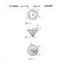
- FIG. 1is a side elevation view of a sprinkler unit in accordance with the invention
- FIG. 2is a view taken on line II--II of FIG. 1;
- FIG. 3is a side elevation view of the distributor head
- FIG. 5is an end view of the distributor head.
- the sprinkler unitdesignated generally by the numeral 10, comprises an elongated generally cylindrical tubular housing 12, having a threaded inlet port 14 at one axial end, which shall be termed the lower end attachable to a suitable source of water under pressure, such as a riser.
- the opposite or upper end of the housingis open and is considered the outlet end thereof.
- the outlet endis provided with outer annular threads 16 for receiving a retainer ring or cap 18 for retaining a pop-up assembly, as will be explained.
- the cap 18has a central bore 20 for accommodating the telescopic extension of an inner tubular pop-up housing or sleeve 22, which is telescopically and reciprocally mounted within the housing 12 for extension upward to an operative position, and retraction to a non-operative position (not shown), as illustrated in FIG. 1.
- the inner housing 22includes a radially extending flange 24 at the lower end thereof, which extends outward and engages the interior surface of the wall of the outer housing 12, and also serves as a retainer for a retracting spring 26, which biases at its lower end against the flange 24 and its upper end against an annular ring 28.
- the ring 28seats against an annular seal 30, which engages the outer surface of the inner housing 22, and is biased against retainer cap 18 by ring 28 and spring 26.
- the driving and flow control structure for the sprinkler unitis mounted on and within the inner housing 22, and carried therewith as the housing is extended upward into the operative position.
- a generally tubular screen 32having radially extending ribs 34, forming a passageway 36 up to and around a damper unit 38 for controlling the velocity of the rotary nozzle, as will be explained.
- the damper unitcomprises a removable stationary housing or stator member, defined by a generally cylindrical stator housing member 40 having a closed end wall 42, and an inner axially extending annular wall 44 forming a tubular extension 44.
- the housing 40includes radial ribs 46, which engages the inner surface of sleeve or inner housing 22 and forms a water flow passage around housing 22.
- the stator housing 40thus forms a housing divided into a central cylindrical chamber 50 and an outer annular chamber 48.
- a rotor unitDisposed within the stator member 40 is a rotor unit, comprising a rotor drum 52 mounted on a rotating shaft 54, which is rotatably mounted within a bore 56 of a housing cap or closure member 58.
- the rotoris complementary to the housing, with central hub 60 on the lower end of the shaft 54 and formed within a cylindrical portion 62, and having an outer sleeve 64 extending into the space or annular chamber 48 between walls 40 and 44 of the stator.
- the opposed cylindrical surfaces of the stator 40 and rotor 52may have ribs for enhancing the drag of the rotor.
- the stator housingis filled with a suitable damping fluid, such as silicone or any suitable viscous damping oil. The viscosity of the damping fluid may be selected to provide the desired damping.
- the drive shaft 54is drivingly connected at its lower o inner end to the rotor 52 by any suitable means, such as splines, keys, press fitting or the like.
- the drive shaft 54extends upward through and is journaled in a bore 72 in a resilient nozzle member 76, and is connected at the upper end to a multiple channel distributing cap or head 68 by means of similar suitable securement in a bore 70.
- the shaftextends along the flow passage, and is sealed in bore 56 by a silicone disc or washer seal 90 within a bore or recess 92 of a hub 94 of housing cap 58.
- the seal 90is biased into sealing engagement with the shaft 54 and the end of hub 60 by water pressure within the flow passage that may leak along bore 56.
- the seal 90is thus located within the damper housing chamber.
- the shaft 54extends through a bore 72 in the nozzle or flow control unit 74, having one or a plurality of flow control nozzles or passages 76 therein.
- the nozzle unit 74has a generally disc shape, with an annular groove portion 78 mounted on an annular rim or tubular extension 80 of an end cap or extension 82 of the inner housing 22.
- An outer annular skirt 84 of the extension unit 82forms retaining cap for the extension of inner housing 22.
- the axially extending end cap portion 84is formed with external threads 86, and threadably engages complementary threads 88 in the upper end of the inner housing or sleeve 22.
- the drive shaft 54is sealed in or at the inner end of bore 56 by an annular seal member 90 seated in a recess 92, and in bore 72 by the resilience of the combined nozzle, journal and seal member 74 (FIG. 2).
- the seal of bore 72 onto shaft 54inhibits the flow of water along the bore between the shaft and bore wall, and inhibits the flow or passing of fine grit and sand into this space.
- the resilience of the member 74enables the wall of bore 72 to yield, and when sand and grit are present, prevents and/or avoids seizing or gripping the shaft.
- the seal 90is essential in that it prevents entry of water into the damping chamber 48 and 50, where it will contaminate the damping fluid therein.
- the damping unitis provided with an expansion chamber in the form of an annular cavity 96 on the inner side of cap 58.
- This annular cavity or chamberis covered by a diaphragm 98 having an inner bore 100 that sealingly engages hub 94 of cap 58.
- the diaphragm 98is sealed at its outer rim against an outer skirt 102 of the cap 58 and/or the inner surface of housing 40.
- This expansion chambercontains air or a gas that accommodates expansion and contraction of the damping fluid within housing 40 and relieves pressure on the seals.
- the distributor head 68is formed with a plurality of combined channels and turbine blades, and serves the dual function of propelling itself and forming and distributing streams of water over a surrounding area.
- the distributor head 68has a somewhat curved or concave frusto-conical outer configuration. As can be seen in FIGS. 1 and 4, the outer surface of the distributor head curves slightly outward from the apex axis to the base of the cone (i.e. top of the cap). A plurality of curved channels or grooves 106 extend from the apex to the base of the cone or top of the head 68.
- channels 106all curve in the same direction around the axis, and each have a vertical wall 108 at the outside of the curve, and a sloped wall 110 on the inside of the curve. These walls form combined flow channels and turbine blades.
- the channelsalso have a continuously increasing depth from the apex to the base.
- One or more nozzles 76 in unit 74delivers one or more shaped streams of water to the apex end of distributing cap 68, which rotates in response thereto.
- the plurality of channels in cap 68forms multiple streams, and directs the streams of water by way of the plurality of flow channels radially outward from the sprinkler unit, and rotates the streams through an arc.
- the streams of water issuing from nozzle 74enter the channels 106 at the apex 112 and flow axially along and radially outward along the channel to its outlet from the head 68.
- the present sprinkler unitis designed to distribute streams of water throughout a selected area. Water will be distributed on the side of the axis having nozzle 76, and the shape of the area will be determined by the cross-sectional shape of the nozzle 76.
- the sprinkler unithas the capability, with proper nozzle configuration, of distributing streams of water over an area having substantially any desired shape, as disclosed in my prior patents. See, for example, my U.S. Pat. Ser. No. 4,842,201, entitled “ROTARY STREAM SPRINKLER UNIT", granted June 27, 1989, and incorporated herein by reference as though fully set forth.
- the sprinkler unitmay be positioned in the center of the area to be covered or to one side thereof. The unit accomplishes this by means of the shape of the nozzle 76 in the unit 74, which controls the volume and velocity of portions of the primary flow stream to the distributor head 68, which forms and distributes each flow stream.
- the distributor head 68(FIGS. 3 and 4) has a plurality of curved channels for forming and rotating each stream across a particular arc or area of the plot determined by the location and shape of the nozzle 76.
- the action of the primary stream of water directed to the rotor or distributor head 68also causes it to rotate.
- the distributor head 68forms its own propelling turbine.
- the distributor caphas a generally horn or conical configuration, with a small diameter lower or inner end 112, and a larger diameter outer or top end 114, with a plurality of curved open water channels 106 extending therebetween.
- the water channels 106each include an inlet end at the apex 112, and an outlet end at the base of the head, with a vertical sidewall 108 and a sloped sidewall 110 extending, as can be seen from FIG. 4, from a minimum depth at the inlet end 112 to a maximum minimum depth extending to the outlet 114.
- the channels 106are curved such that the outlet end at 104 is at an angle to a radial through the axis of the distributor cap.
- the channelsthus form turbine blades that drive or rotate the distributor head 68 in response to one or more streams of water, striking it from one or more nozzles or passage 76.
- An annular skirt 114 on the inside of cap member 82aids in directing the flow of water into the channels 106.
- the channels 106form a plurality of final streams from each arcuate stream directed thereto via passage 76.
- the distributor headas can be seen in FIG. 1, sits directly over the flow nozzle 74, and the inner or lower ends of the channels 106 are disposed directly over the outlet of the flow passage or passages 76. It is nestled within a protective cavity formed by member 82.
- an outlet of a stream passage 74is directed into the inner end of the flow channels 106, which causes rotation of the rotary distributor head 68.
- the rotation of the headdirects the outer end of the flow stream along an arc at the end of its reach.
- a flow streamwill have somewhat of an arc shape, and is directed into the inner end at apex 112 of a plurality of the flow channels 106.
- the streamwill continue to flow into a channel, with a rotation of the cap along an arc as long as the channel overlaps the passage or nozzle 74, as shown.
- the length of the arc at the outer end of the streamwill be determined by width of nozzle outlet 76, and the radius from the center axis of the rotor to the position of striking of the stream at its outer end.
- a particular flow channel 106maintains communication with the flow passage for a certain degree of rotation thereof.
- the inner end of the flow channelis in communication with a particular nozzle or flow passage, a portion of the water from that flow passage will be directed along the flow channel 106, along an arc determined by where the inner end of the flow channel picks up the flow passage, and where it drops that flow passage for the next one.
- a particular channel 106will pick up and distribute flow from a flow passage 76, or the flow passages disposed around the flow control unit in sequence in the direction of rotation of the distributing cap.
- a portion of each primary flow streamwill be in sequence, picked up by a flow channel 106 as it registers with that stream, and will distribute it along an arc or direct it along an arc as the cap rotates.
- the length of the stream and its coverage of the surface areawill be determined by the volume, velocity and other characteristics of the stream, as determined by the configuration of nozzle 76.
- the damper unitwill impose a drag on the distributor head, so that it will maintain a reasonable velocity of rotation for a given range of water pressure.
- a reasonably low rate of rotationwill enable the streams from channels 106 to maintain a stream and attain a maximum reach.
- Meansmay be provided, such as knobs or the like, along the outer rim of the distributor head to extend into a few of the streams from the channels 106, to break up the streams and distribute water inwardly toward the sprinkler unit from the streams normal outer reach.
Landscapes
- Nozzles (AREA)
Abstract
Description
The present invention relates to sprinkler units, and pertains particularly to a rotary stream sprinkler unit with damping means.
In my prior Pat. Ser. No. 3,854,664, issued Dec. 17, 1974, entitled "SPRINKLER SYSTEMS", I disclose a sprinkler unit which has a rotating head that directs a plurality of rotating streams over an area to be watered. The streams of water are formed in nozzles in the rotating head. The rotating head has inlets to the nozzle on one end, which engages and cooperates with an orifice plate for acting as a valve for controlling communication of pressurized water to the nozzles. A turbine and reduction gear unit drives the head at a controlled velocity.
My U.S. Pat. Ser. No. 4,471,908, issued Sept. 18, 1984, entitled "PATTERN SPRINKLER HEAD", discloses a similar sprinkler unit having V-shaped nozzles in a cylindrical rotating head. The nozzle inlet openings cooperate with an orifice in an orifice plate to vary the nozzle openings to the source of pressurized water. This combination delivers streams of water of variable length and volume from the nozzles in the distributor head. The rotating head is driven at a substantially constant velocity or rate of rotation by means of a turbine and reduction drive gearing. Such construction is complex and expensive to manufacture.
In a subsequent application co-pending herewith, a plurality of passages in the unit forms nozzles which controls the stream size and velocity delivered to an open channel distributing head. The streams from the nozzles are directed into a plurality of open channels on a rotating distributor head for forming and distributing the streams.
The rotating head in the above described units is driven by a turbine through a reduction drive gear assembly within the body of the sprinkler unit.
Sprinkler heads have been known wherein the distributor head is self-propelling, or more particularly stream propelled. The sprinkler head is rotated either by streams of water flowing from jets or nozzles in the head, or by blades on the head struck by a stream of water causing it to rotate.
Among the problems of the prior art self-propelled device is that it is difficult to control the velocity of rotation of the head. The velocity of rotation of the head is affected by friction, stream pressure and velocity, and other factors, which ultimately determine the reach or distance that the distributed water travels from the head. The higher the velocity of rotation of the head, the shorter the reach of the streams from the head will be.
The present invention is an improvement in the invention in my prior Pat. Ser. No. 4,815,662, issued Mar. 28, 1989, entitled "STREAM PROPELLED ROTARY STREAM SPRINKLER UNIT WITH DAMPING MEANS", which is incorporated herein by reference as though fully set forth. In that patent, I disclose a sprinkler unit which has a rotating head that is self-propelled and directs a plurality of rotating streams over an area to be watered. The velocity of the rotating head is controlled by means of a damping unit inside the sprinkler housing and connected to the head by a common rotatable shaft. A nozzle in the housing shapes the stream to the rotating head, and the streams of water directed outward are formed in nozzles in the rotating head. The rotating shaft is mounted in a damper unit housing at the inner end and in a portion of the housing at the outer end. Sealing of the shaft against fine sand and grit and against water leakage into the damper unit is a major problem.
Some attempts have been made in the past to control the velocity of rotation of the distributor head by some type of damping means. However, these attempts have been unsatisfactory.
Accordingly, it is desirable that an improved rotary stream sprinkler unit be available.
It is therefore the primary object of the present invention to provide an improved rotary stream sprinkler unit.
In accordance with the primary aspect of the present invention, a rotary stream sprinkler unit comprises a housing having one or more stream nozzles for providing a predetermined stream volume and velocity, with a multiple channel rotor positioned at the outlet of the flow passages, rotating in response to the stream, and for dividing the stream into a plurality of streams, and selectively distributing the streams over a predetermined area, with an improved damping means for controlling the velocity of rotation of the distributor head.
The above and other objects and advantages of the present invention will become apparent from the following description when read in conjunction with the drawings wherein:
FIG. 1 is a side elevation view of a sprinkler unit in accordance with the invention;
FIG. 2 is a view taken on line II--II of FIG. 1;
FIG. 3 is a side elevation view of the distributor head; and
FIG. 5 is an end view of the distributor head.
Referring to FIG. 1 of the drawings, there is illustrated a sprinkler unit constructed in accordance with a preferred embodiment of the invention. The sprinkler unit, designated generally by thenumeral 10, comprises an elongated generally cylindricaltubular housing 12, having a threadedinlet port 14 at one axial end, which shall be termed the lower end attachable to a suitable source of water under pressure, such as a riser.
The opposite or upper end of the housing is open and is considered the outlet end thereof. The outlet end is provided with outerannular threads 16 for receiving a retainer ring orcap 18 for retaining a pop-up assembly, as will be explained. Thecap 18 has acentral bore 20 for accommodating the telescopic extension of an inner tubular pop-up housing orsleeve 22, which is telescopically and reciprocally mounted within thehousing 12 for extension upward to an operative position, and retraction to a non-operative position (not shown), as illustrated in FIG. 1.
Theinner housing 22 includes a radially extendingflange 24 at the lower end thereof, which extends outward and engages the interior surface of the wall of theouter housing 12, and also serves as a retainer for a retractingspring 26, which biases at its lower end against theflange 24 and its upper end against anannular ring 28. Thering 28 seats against anannular seal 30, which engages the outer surface of theinner housing 22, and is biased againstretainer cap 18 byring 28 andspring 26.
The driving and flow control structure for the sprinkler unit is mounted on and within theinner housing 22, and carried therewith as the housing is extended upward into the operative position. Mounted within the lower end of theinner housing 22, within the tubular central bore thereof, is a generallytubular screen 32 having radially extendingribs 34, forming a passageway 36 up to and around a damper unit 38 for controlling the velocity of the rotary nozzle, as will be explained.
The damper unit comprises a removable stationary housing or stator member, defined by a generally cylindricalstator housing member 40 having a closedend wall 42, and an inner axially extending annular wall 44 forming a tubular extension 44. Thehousing 40 includesradial ribs 46, which engages the inner surface of sleeve orinner housing 22 and forms a water flow passage aroundhousing 22. Thestator housing 40 thus forms a housing divided into a centralcylindrical chamber 50 and an outerannular chamber 48.
Disposed within thestator member 40 is a rotor unit, comprising arotor drum 52 mounted on a rotating shaft 54, which is rotatably mounted within abore 56 of a housing cap orclosure member 58. The rotor is complementary to the housing, withcentral hub 60 on the lower end of the shaft 54 and formed within a cylindrical portion 62, and having anouter sleeve 64 extending into the space orannular chamber 48 betweenwalls 40 and 44 of the stator. The opposed cylindrical surfaces of thestator 40 androtor 52 may have ribs for enhancing the drag of the rotor. The stator housing is filled with a suitable damping fluid, such as silicone or any suitable viscous damping oil. The viscosity of the damping fluid may be selected to provide the desired damping.
The drive shaft 54 is drivingly connected at its lower o inner end to therotor 52 by any suitable means, such as splines, keys, press fitting or the like. The drive shaft 54 extends upward through and is journaled in abore 72 in aresilient nozzle member 76, and is connected at the upper end to a multiple channel distributing cap orhead 68 by means of similar suitable securement in a bore 70. The shaft extends along the flow passage, and is sealed inbore 56 by a silicone disc or washer seal 90 within a bore or recess 92 of ahub 94 ofhousing cap 58. The seal 90 is biased into sealing engagement with the shaft 54 and the end ofhub 60 by water pressure within the flow passage that may leak alongbore 56. The seal 90 is thus located within the damper housing chamber.
The shaft 54 extends through abore 72 in the nozzle orflow control unit 74, having one or a plurality of flow control nozzles orpassages 76 therein. Thenozzle unit 74 has a generally disc shape, with anannular groove portion 78 mounted on an annular rim or tubular extension 80 of an end cap or extension 82 of theinner housing 22. An outerannular skirt 84 of the extension unit 82 forms retaining cap for the extension ofinner housing 22. The axially extendingend cap portion 84 is formed withexternal threads 86, and threadably engagescomplementary threads 88 in the upper end of the inner housing orsleeve 22. Thus, flow control o nozzle units having different shape and size nozzles can be selectively mounted in any one sprinkler unit
The drive shaft 54 is sealed in or at the inner end ofbore 56 by an annular seal member 90 seated in arecess 92, and inbore 72 by the resilience of the combined nozzle, journal and seal member 74 (FIG. 2). The seal ofbore 72 onto shaft 54 inhibits the flow of water along the bore between the shaft and bore wall, and inhibits the flow or passing of fine grit and sand into this space. In addition, the resilience of themember 74 enables the wall ofbore 72 to yield, and when sand and grit are present, prevents and/or avoids seizing or gripping the shaft. The seal 90 is essential in that it prevents entry of water into the dampingchamber
The damping unit is provided with an expansion chamber in the form of anannular cavity 96 on the inner side ofcap 58. This annular cavity or chamber is covered by adiaphragm 98 having aninner bore 100 that sealingly engageshub 94 ofcap 58. Thediaphragm 98 is sealed at its outer rim against anouter skirt 102 of thecap 58 and/or the inner surface ofhousing 40. This expansion chamber contains air or a gas that accommodates expansion and contraction of the damping fluid withinhousing 40 and relieves pressure on the seals.
Referring to FIGS. 3 and 4, thedistributor head 68 is formed with a plurality of combined channels and turbine blades, and serves the dual function of propelling itself and forming and distributing streams of water over a surrounding area. Thedistributor head 68 has a somewhat curved or concave frusto-conical outer configuration. As can be seen in FIGS. 1 and 4, the outer surface of the distributor head curves slightly outward from the apex axis to the base of the cone (i.e. top of the cap). A plurality of curved channels orgrooves 106 extend from the apex to the base of the cone or top of thehead 68. Thesechannels 106 all curve in the same direction around the axis, and each have avertical wall 108 at the outside of the curve, and asloped wall 110 on the inside of the curve. These walls form combined flow channels and turbine blades. The channels also have a continuously increasing depth from the apex to the base.
One ormore nozzles 76 inunit 74, which will be further explained hereinafter, delivers one or more shaped streams of water to the apex end of distributingcap 68, which rotates in response thereto. The plurality of channels incap 68 forms multiple streams, and directs the streams of water by way of the plurality of flow channels radially outward from the sprinkler unit, and rotates the streams through an arc. The streams of water issuing fromnozzle 74 enter thechannels 106 at the apex 112 and flow axially along and radially outward along the channel to its outlet from thehead 68.
The present sprinkler unit, as described above, is designed to distribute streams of water throughout a selected area. Water will be distributed on the side of theaxis having nozzle 76, and the shape of the area will be determined by the cross-sectional shape of thenozzle 76. For example, the sprinkler unit has the capability, with proper nozzle configuration, of distributing streams of water over an area having substantially any desired shape, as disclosed in my prior patents. See, for example, my U.S. Pat. Ser. No. 4,842,201, entitled "ROTARY STREAM SPRINKLER UNIT", granted June 27, 1989, and incorporated herein by reference as though fully set forth. The sprinkler unit may be positioned in the center of the area to be covered or to one side thereof. The unit accomplishes this by means of the shape of thenozzle 76 in theunit 74, which controls the volume and velocity of portions of the primary flow stream to thedistributor head 68, which forms and distributes each flow stream.
The distributor head 68 (FIGS. 3 and 4) has a plurality of curved channels for forming and rotating each stream across a particular arc or area of the plot determined by the location and shape of thenozzle 76. The action of the primary stream of water directed to the rotor ordistributor head 68 also causes it to rotate. Thus, thedistributor head 68 forms its own propelling turbine.
An appreciation of the construction and operation of the distributor head will be obtained from a view of FIGS. 3 and 4 and the following explanation herein. As shown in FIGS. 3 and 4, the distributor cap has a generally horn or conical configuration, with a small diameter lower or inner end 112, and a larger diameter outer ortop end 114, with a plurality of curvedopen water channels 106 extending therebetween. Thewater channels 106 each include an inlet end at the apex 112, and an outlet end at the base of the head, with avertical sidewall 108 and asloped sidewall 110 extending, as can be seen from FIG. 4, from a minimum depth at the inlet end 112 to a maximum minimum depth extending to theoutlet 114. Thechannels 106 are curved such that the outlet end at 104 is at an angle to a radial through the axis of the distributor cap.
The channels thus form turbine blades that drive or rotate thedistributor head 68 in response to one or more streams of water, striking it from one or more nozzles orpassage 76. Anannular skirt 114 on the inside of cap member 82 aids in directing the flow of water into thechannels 106. Thechannels 106 form a plurality of final streams from each arcuate stream directed thereto viapassage 76. The distributor head, as can be seen in FIG. 1, sits directly over theflow nozzle 74, and the inner or lower ends of thechannels 106 are disposed directly over the outlet of the flow passage orpassages 76. It is nestled within a protective cavity formed by member 82.
As will be appreciated from FIGS. 3 and 4, an outlet of astream passage 74 is directed into the inner end of theflow channels 106, which causes rotation of therotary distributor head 68. The rotation of the head directs the outer end of the flow stream along an arc at the end of its reach. A flow stream will have somewhat of an arc shape, and is directed into the inner end at apex 112 of a plurality of theflow channels 106. The stream will continue to flow into a channel, with a rotation of the cap along an arc as long as the channel overlaps the passage ornozzle 74, as shown.
The length of the arc at the outer end of the stream will be determined by width ofnozzle outlet 76, and the radius from the center axis of the rotor to the position of striking of the stream at its outer end. Thus, as the distributing cap is rotating, aparticular flow channel 106 maintains communication with the flow passage for a certain degree of rotation thereof. As long as the inner end of the flow channel is in communication with a particular nozzle or flow passage, a portion of the water from that flow passage will be directed along theflow channel 106, along an arc determined by where the inner end of the flow channel picks up the flow passage, and where it drops that flow passage for the next one.
As the distributing cap rotates, aparticular channel 106 will pick up and distribute flow from aflow passage 76, or the flow passages disposed around the flow control unit in sequence in the direction of rotation of the distributing cap. Thus, a portion of each primary flow stream will be in sequence, picked up by aflow channel 106 as it registers with that stream, and will distribute it along an arc or direct it along an arc as the cap rotates. The length of the stream and its coverage of the surface area will be determined by the volume, velocity and other characteristics of the stream, as determined by the configuration ofnozzle 76.
The damper unit will impose a drag on the distributor head, so that it will maintain a reasonable velocity of rotation for a given range of water pressure. A reasonably low rate of rotation will enable the streams fromchannels 106 to maintain a stream and attain a maximum reach. Means may be provided, such as knobs or the like, along the outer rim of the distributor head to extend into a few of the streams from thechannels 106, to break up the streams and distribute water inwardly toward the sprinkler unit from the streams normal outer reach.
While I have illustrated and described my invention by means of a specific embodiment, it is to be understood that numerous changes and modifications may be made therein without departing from the spirit and scope of the invention as defined in the appended claims.
Claims (19)
1. A rotating stream sprinkler unit comprising:
a tubular housing having a central axis, an inlet, an outlet, and a flow passage communicating therebetween for conducting a primary stream of water from said inlet to said outlet;
distributor means rotatably mounted at said outlet for receiving said primary stream of water, for rotating in response thereto, and for directing said stream outward from the axis of said housing over a selected area;
damping means disposed in said housing up stream of said outlet and operatively connected to said distributor means by a rotatable shaft extending along said flow passage for controlling the velocity of rotation thereof; and
resilient means at said outlet for rotatably supporting said shaft.
2. A rotary stream sprinkler according to claim 1 wherein:
said resilient means comprises a circular disc having a central bore for supporting said shaft and a nozzle adjacent said bore for forming said primary stream.
3. A sprinkler unit according to claim 2 wherein: said damping means comprises a generally cylindrical chamber in said housing;
a quantity of damping fluid in said chamber; and
a generally cylindrical rotor on said shaft disposed in said chamber.
4. A sprinkler unit according to claim 3 wherein:
said chamber includes annular wall means therein; and
said rotor includes means defining an annular recess for receiving said annular wall means.
5. A sprinkler unit according to claim 4 wherein:
said damping means is disposed coaxially within said housing upstream of said outlet.
6. A sprinkler unit according to claim 5 wherein:
said rotor and said distributor means are connected by said shaft extending coaxially along said flow passage.
7. A rotary stream sprinkler according to claim 1 wherein:
said distributor means comprises a distributor head having a plurality of curved axially and radially extending flow channels for defining turbine blades and for forming and directing a plurality of individual streams outward therefrom.
8. A rotary stream sprinkler according to claim 1 wherein:
said distributor means comprises a generally conical shaped member having a plurality of curved grooves extending along the conical surface thereof from the apex to the base thereof; and
said apex is disposed at said outlet.
9. A sprinkler unit according to claim 1 wherein:
a body member mounted in said flow passage; and
at least one substantially arcuate nozzle in said body member disposed in a circular arc and extending along said body member parallel to said central axis toward said outlet.
10. A rotary stream sprinkler according to claim 1 wherein:
said distributor means comprises a generally conical shaped member having a plurality of curved grooves extending along a conical surface thereof from an apex to a base thereof; and
said apex is disposed at said outlet.
11. A sprinkler unit according to claim 10 wherein:
a body member mounted in said flow passage; and
at least one substantially arcuate flow passage in said body member disposed in a circular arc and extending along said body member parallel to said central axis toward said outlet.
12. A sprinkler unit according to claim 11 wherein:
said damping means comprises a generally cylindrical chamber in said housing;
a quantity of damping fluid in said housing; and
a generally cylindrical rotor disposed in said chamber.
13. A rotary stream sprinkler unit comprising:
a tubular housing having a central axis, an inlet, an outlet, and a flow passage communicating therebetween for conducting a primary stream of water from said inlet to said outlet;
an elongated rotor shaft rotatably mounted at said outlet and having an inner end and an outer end;
resilient support means for rotatably supporting the outer end of said elongated shaft;
distributor means mounted on the outer end of said shaft for receiving said primary stream of water, for rotating in response thereto, and for directing said stream outward from the axis of said housing over a selected area;
damping means disposed in said housing on the inner end of said elongated shaft for controlling the velocity of rotation of said distributor means.
14. A rotary stream sprinkler according to claim 13 wherein:
said distributor means and said damping means are mounted on a common shaft coaxially of said central axis.
15. A rotary stream sprinkler according to claim 14 wherein:
said distributor means comprises a distributor head having a plurality of curved radially extending flow channels.
16. A rotary stream sprinkler according to claim 14 wherein:
said distributor head comprises a generally conical shaped member having a plurality of curved grooves extending along a conical surface thereof from an apex to a base thereof; and
said apex is disposed at said outlet.
17. A sprinkler unit according to claim 16 wherein:
a body member mounted in said channel; and
at least one substantially arcuate flow passage in said body member disposed in a circular arc and extending along said body member parallel to said central axis toward said outlet.
18. A sprinkler unit according to claim 17 wherein:
said damping means comprises a generally cylindrical chamber in said housing;
a quantity of damping fluid in said housing; and
a generally cylindrical rotor disposed in said chamber.
19. A sprinkler unit according to claim 18 wherein:
said chamber includes annular wall means therein; and
said rotor includes means defining an annular recess for receiving said annular wall means.
Priority Applications (2)
| Application Number | Priority Date | Filing Date | Title |
|---|---|---|---|
| US07/389,946US4932590A (en) | 1989-08-07 | 1989-08-07 | Rotary stream sprinkler unit with rotor damping means |
| US07/444,292US4971250A (en) | 1989-08-07 | 1989-12-01 | Rotary stream sprinkler unit with rotor damping means |
Applications Claiming Priority (1)
| Application Number | Priority Date | Filing Date | Title |
|---|---|---|---|
| US07/389,946US4932590A (en) | 1989-08-07 | 1989-08-07 | Rotary stream sprinkler unit with rotor damping means |
Related Child Applications (1)
| Application Number | Title | Priority Date | Filing Date |
|---|---|---|---|
| US07/444,292Continuation-In-PartUS4971250A (en) | 1989-08-07 | 1989-12-01 | Rotary stream sprinkler unit with rotor damping means |
Publications (1)
| Publication Number | Publication Date |
|---|---|
| US4932590Atrue US4932590A (en) | 1990-06-12 |
Family
ID=23540425
Family Applications (1)
| Application Number | Title | Priority Date | Filing Date |
|---|---|---|---|
| US07/389,946Expired - LifetimeUS4932590A (en) | 1989-08-07 | 1989-08-07 | Rotary stream sprinkler unit with rotor damping means |
Country Status (1)
| Country | Link |
|---|---|
| US (1) | US4932590A (en) |
Cited By (55)
| Publication number | Priority date | Publication date | Assignee | Title |
|---|---|---|---|---|
| US4971250A (en)* | 1989-08-07 | 1990-11-20 | Hunter Edwin J | Rotary stream sprinkler unit with rotor damping means |
| US4986474A (en)* | 1989-08-07 | 1991-01-22 | Nelson Irrigation Corporation | Stream propelled rotary pop-up sprinkler |
| US5288022A (en)* | 1991-11-08 | 1994-02-22 | Nelson Irrigation Corporation | Part circle rotator with improved nozzle assembly |
| EP0826426A3 (en)* | 1996-08-24 | 1998-11-18 | GARDENA Kress + Kastner GmbH | Sprinkler |
| US5909848A (en)* | 1998-07-17 | 1999-06-08 | Stoneage, Inc. | High pressure liquid rotary nozzle with coil spring retarder |
| US6000634A (en)* | 1997-08-20 | 1999-12-14 | Hydroplan Engineering Ltd. | Irrigation sprinkler |
| US6244521B1 (en) | 1999-11-03 | 2001-06-12 | Nelson Irrigation Corporation | Micro-stream rotator with adjustment of throw radius and flow rate |
| WO2002078857A1 (en) | 2001-03-28 | 2002-10-10 | Nelson Irrigation Corporation | Adjustable arc, adjustable flow rate sprinkler |
| US6499672B1 (en) | 1999-11-03 | 2002-12-31 | Nelson Irrigation Corporation | Micro-stream rotator with adjustment of throw radius and flow rate |
| US20030075620A1 (en)* | 2001-07-25 | 2003-04-24 | Kah Carl L.C. | Selected range arc settable spray nozzle with pre-set proportional connected upstream flow throttling |
| WO2003086643A1 (en) | 2002-04-10 | 2003-10-23 | Nelson Irrigation Corporation | Adjustable arc, adjustable flow rate sprinkler |
| US20040050955A1 (en)* | 2001-03-28 | 2004-03-18 | Nelson Irrigation Corporation | Adjustable arc, adjustable flow rate sprinkler |
| US20040164178A1 (en)* | 2003-02-07 | 2004-08-26 | Kah, Carl L.C. | Speed limiting for rotary driven sprinkler |
| WO2004085077A1 (en) | 2003-03-24 | 2004-10-07 | Plastro Irrigation A.C.S Ltd. | Revolving sprinkler |
| US20040195362A1 (en)* | 2003-04-02 | 2004-10-07 | Walker Samuel C. | Rotating stream sprinkler with torque balanced reaction drive |
| US6814304B2 (en) | 2002-12-04 | 2004-11-09 | Rain Bird Corporation | Rotating stream sprinkler with speed control brake |
| US20060192029A1 (en)* | 2005-02-28 | 2006-08-31 | Glendale Grizzle | Rotary stream sprinkler with adjustable deflector ring |
| USD527791S1 (en) | 2002-12-04 | 2006-09-05 | Rain Bird Corporation | Sprinkler |
| US7152814B1 (en) | 2004-02-02 | 2006-12-26 | Orbit Irrigation Products, Inc. | Adjustable spray pattern sprinkler |
| US20070012800A1 (en)* | 2005-07-15 | 2007-01-18 | Rain Bird Corporation | Speed control apparatus for a rotary sprinkler |
| US20070181711A1 (en)* | 2006-02-08 | 2007-08-09 | Nelson Irrigation Corporation | Adjustable flow rate, rectangular pattern sprinkler |
| EP1849526A3 (en)* | 2006-04-24 | 2008-08-20 | Nelson Irrigation Corporation | Sprinkler with viscous hesitator |
| US7429005B2 (en) | 2004-02-02 | 2008-09-30 | Orbit Irrigation Products, Inc. | Adjustable spray pattern sprinkler |
| US20080257982A1 (en)* | 2007-04-19 | 2008-10-23 | Kah Carl L C | Sprinkler head nozzle assembly with adjustable arc, flow rate and stream angle |
| US20080308650A1 (en)* | 2007-06-13 | 2008-12-18 | Clark Michael L | Gear Driven Sprinkler with Top Turbine |
| US20090108099A1 (en)* | 2007-10-30 | 2009-04-30 | Porter Lamonte D | Rotary Stream Sprinkler Nozzle with Offset Flutes |
| US20090224070A1 (en)* | 2008-03-07 | 2009-09-10 | Clark Michael L | Hydraulically Actuated Sprinkler Nozzle Cover |
| US20100090024A1 (en)* | 2008-10-09 | 2010-04-15 | Steven Brian Hunnicutt | Sprinkler with variable arc and flow rate |
| DE102009017293A1 (en)* | 2009-04-11 | 2010-10-14 | Gardena Manufacturing Gmbh | Regner |
| US20100301135A1 (en)* | 2009-05-29 | 2010-12-02 | Steven Brian Hunnicutt | Sprinkler with Variable Arc and Flow Rate and Method |
| US20100301142A1 (en)* | 2009-05-29 | 2010-12-02 | Rain Bird Corporation | Sprinkler with variable arc and flow rate and method |
| US20110057048A1 (en)* | 2009-09-08 | 2011-03-10 | Mcafee Michael Albert | Irrigation device |
| US8651400B2 (en) | 2007-01-12 | 2014-02-18 | Rain Bird Corporation | Variable arc nozzle |
| US8783582B2 (en) | 2010-04-09 | 2014-07-22 | Rain Bird Corporation | Adjustable arc irrigation sprinkler nozzle configured for positive indexing |
| US8925837B2 (en) | 2009-05-29 | 2015-01-06 | Rain Bird Corporation | Sprinkler with variable arc and flow rate and method |
| US9079202B2 (en) | 2012-06-13 | 2015-07-14 | Rain Bird Corporation | Rotary variable arc nozzle |
| US9174227B2 (en) | 2012-06-14 | 2015-11-03 | Rain Bird Corporation | Irrigation sprinkler nozzle |
| US9192110B2 (en) | 2010-08-11 | 2015-11-24 | The Toro Company | Central irrigation control system |
| US9295998B2 (en) | 2012-07-27 | 2016-03-29 | Rain Bird Corporation | Rotary nozzle |
| US9314952B2 (en) | 2013-03-14 | 2016-04-19 | Rain Bird Corporation | Irrigation spray nozzle and mold assembly and method of forming nozzle |
| US9327297B2 (en) | 2012-07-27 | 2016-05-03 | Rain Bird Corporation | Rotary nozzle |
| US9427751B2 (en) | 2010-04-09 | 2016-08-30 | Rain Bird Corporation | Irrigation sprinkler nozzle having deflector with micro-ramps |
| US9492832B2 (en) | 2013-03-14 | 2016-11-15 | Rain Bird Corporation | Sprinkler with brake assembly |
| US9504209B2 (en) | 2010-04-09 | 2016-11-29 | Rain Bird Corporation | Irrigation sprinkler nozzle |
| US9700904B2 (en) | 2014-02-07 | 2017-07-11 | Rain Bird Corporation | Sprinkler |
| US9808813B1 (en) | 2007-10-30 | 2017-11-07 | Hunter Industries, Inc. | Rotary stream sprinkler nozzle with offset flutes |
| US10322423B2 (en) | 2016-11-22 | 2019-06-18 | Rain Bird Corporation | Rotary nozzle |
| US10350619B2 (en) | 2013-02-08 | 2019-07-16 | Rain Bird Corporation | Rotary sprinkler |
| US11000866B2 (en) | 2019-01-09 | 2021-05-11 | Rain Bird Corporation | Rotary nozzles and deflectors |
| US11059056B2 (en) | 2019-02-28 | 2021-07-13 | Rain Bird Corporation | Rotary strip nozzles and deflectors |
| US11154877B2 (en) | 2017-03-29 | 2021-10-26 | Rain Bird Corporation | Rotary strip nozzles |
| US11247219B2 (en) | 2019-11-22 | 2022-02-15 | Rain Bird Corporation | Reduced precipitation rate nozzle |
| US11406999B2 (en) | 2019-05-10 | 2022-08-09 | Rain Bird Corporation | Irrigation nozzle with one or more grit vents |
| US11511289B2 (en) | 2017-07-13 | 2022-11-29 | Rain Bird Corporation | Rotary full circle nozzles and deflectors |
| US12296353B2 (en) | 2021-03-18 | 2025-05-13 | Hunter Industries, Inc. | Spray head sprinkler |
Citations (10)
| Publication number | Priority date | Publication date | Assignee | Title |
|---|---|---|---|---|
| US3006558A (en)* | 1958-03-19 | 1961-10-31 | Arthur W Jacobs | Lawn sprinkler nozzle |
| US3052574A (en)* | 1958-05-14 | 1962-09-04 | Pyrate Sales Inc | Tank cleaning device and method |
| US3854664A (en)* | 1973-03-30 | 1974-12-17 | Toro Co | Sprinkler systems |
| US4440345A (en)* | 1979-08-30 | 1984-04-03 | Oesterreichische Salen-Kunststoffwerk Gesellschaft M.B.H. | Sprinkler |
| US4471908A (en)* | 1981-03-09 | 1984-09-18 | The Toro Company | Pattern sprinkler head |
| US4624412A (en)* | 1984-09-10 | 1986-11-25 | Hunter Edwin J | Reversible turbine driven sprinkler unit |
| US4660766A (en)* | 1985-09-18 | 1987-04-28 | Nelson Irrigation Corporation | Rotary sprinkler head |
| US4796811A (en)* | 1988-04-12 | 1989-01-10 | Nelson Irrigation Corporation | Sprinkler having a flow rate compensating slow speed rotary distributor |
| US4815662A (en)* | 1987-11-23 | 1989-03-28 | Hunter Edwin J | Stream propelled rotary stream sprinkler unit with damping means |
| US4842201A (en)* | 1986-06-26 | 1989-06-27 | Hunter Edwin J | Rotary stream sprinkler unit |
- 1989
- 1989-08-07USUS07/389,946patent/US4932590A/ennot_activeExpired - Lifetime
Patent Citations (11)
| Publication number | Priority date | Publication date | Assignee | Title |
|---|---|---|---|---|
| US3006558A (en)* | 1958-03-19 | 1961-10-31 | Arthur W Jacobs | Lawn sprinkler nozzle |
| US3052574A (en)* | 1958-05-14 | 1962-09-04 | Pyrate Sales Inc | Tank cleaning device and method |
| US3854664A (en)* | 1973-03-30 | 1974-12-17 | Toro Co | Sprinkler systems |
| US3854664B1 (en)* | 1973-03-30 | 1986-01-21 | ||
| US4440345A (en)* | 1979-08-30 | 1984-04-03 | Oesterreichische Salen-Kunststoffwerk Gesellschaft M.B.H. | Sprinkler |
| US4471908A (en)* | 1981-03-09 | 1984-09-18 | The Toro Company | Pattern sprinkler head |
| US4624412A (en)* | 1984-09-10 | 1986-11-25 | Hunter Edwin J | Reversible turbine driven sprinkler unit |
| US4660766A (en)* | 1985-09-18 | 1987-04-28 | Nelson Irrigation Corporation | Rotary sprinkler head |
| US4842201A (en)* | 1986-06-26 | 1989-06-27 | Hunter Edwin J | Rotary stream sprinkler unit |
| US4815662A (en)* | 1987-11-23 | 1989-03-28 | Hunter Edwin J | Stream propelled rotary stream sprinkler unit with damping means |
| US4796811A (en)* | 1988-04-12 | 1989-01-10 | Nelson Irrigation Corporation | Sprinkler having a flow rate compensating slow speed rotary distributor |
Cited By (101)
| Publication number | Priority date | Publication date | Assignee | Title |
|---|---|---|---|---|
| US4971250A (en)* | 1989-08-07 | 1990-11-20 | Hunter Edwin J | Rotary stream sprinkler unit with rotor damping means |
| US4986474A (en)* | 1989-08-07 | 1991-01-22 | Nelson Irrigation Corporation | Stream propelled rotary pop-up sprinkler |
| US5288022A (en)* | 1991-11-08 | 1994-02-22 | Nelson Irrigation Corporation | Part circle rotator with improved nozzle assembly |
| EP0826426A3 (en)* | 1996-08-24 | 1998-11-18 | GARDENA Kress + Kastner GmbH | Sprinkler |
| US5845849A (en)* | 1996-08-24 | 1998-12-08 | Gardena Kress + Dastner GmbH | Sprinkler |
| US6000634A (en)* | 1997-08-20 | 1999-12-14 | Hydroplan Engineering Ltd. | Irrigation sprinkler |
| WO2000003811A1 (en)* | 1998-07-17 | 2000-01-27 | Stoneage, Inc. | Liquid rotary nozzle with coil spring retarder |
| AU757552B2 (en)* | 1998-07-17 | 2003-02-27 | Stoneage, Inc. | Liquid rotary nozzle with coil spring retarder |
| US5909848A (en)* | 1998-07-17 | 1999-06-08 | Stoneage, Inc. | High pressure liquid rotary nozzle with coil spring retarder |
| USRE42596E1 (en) | 1999-11-03 | 2011-08-09 | Hunter Industries, Inc. | Micro-stream rotator with adjustment of throw radius and flow rate |
| US6244521B1 (en) | 1999-11-03 | 2001-06-12 | Nelson Irrigation Corporation | Micro-stream rotator with adjustment of throw radius and flow rate |
| USRE40440E1 (en) | 1999-11-03 | 2008-07-22 | Hunter Industries Incorporated | Micro-stream rotator with adjustment of throw radius and flow rate |
| US6499672B1 (en) | 1999-11-03 | 2002-12-31 | Nelson Irrigation Corporation | Micro-stream rotator with adjustment of throw radius and flow rate |
| USRE45263E1 (en) | 1999-11-03 | 2014-12-02 | Hunter Industries Incorporated | Micro-stream rotator with adjustment of throw radius and flow rate |
| US7032836B2 (en) | 2001-03-28 | 2006-04-25 | Nelson Irrigation Corporation | Adjustable arc, adjustable flow rate sprinkler |
| US6651905B2 (en) | 2001-03-28 | 2003-11-25 | Nelson Irrigation Corporation | Adjustable arc, adjustable flow rate sprinkler |
| WO2002078857A1 (en) | 2001-03-28 | 2002-10-10 | Nelson Irrigation Corporation | Adjustable arc, adjustable flow rate sprinkler |
| US7159795B2 (en) | 2001-03-28 | 2007-01-09 | Nelson Irrigation Corporation | Adjustable arc, adjustable flow rate sprinkler |
| US20040050955A1 (en)* | 2001-03-28 | 2004-03-18 | Nelson Irrigation Corporation | Adjustable arc, adjustable flow rate sprinkler |
| US20040227007A1 (en)* | 2001-03-28 | 2004-11-18 | Nelson Irrigation Corporation | Adjustable arc, adjustable flow rate sprinkler |
| US20030075620A1 (en)* | 2001-07-25 | 2003-04-24 | Kah Carl L.C. | Selected range arc settable spray nozzle with pre-set proportional connected upstream flow throttling |
| US6834816B2 (en)* | 2001-07-25 | 2004-12-28 | Carl L. C. Kah, Jr. | Selected range arc settable spray nozzle with pre-set proportional connected upstream flow throttling |
| WO2003086643A1 (en) | 2002-04-10 | 2003-10-23 | Nelson Irrigation Corporation | Adjustable arc, adjustable flow rate sprinkler |
| US6814304B2 (en) | 2002-12-04 | 2004-11-09 | Rain Bird Corporation | Rotating stream sprinkler with speed control brake |
| USD527791S1 (en) | 2002-12-04 | 2006-09-05 | Rain Bird Corporation | Sprinkler |
| US20050082387A1 (en)* | 2002-12-04 | 2005-04-21 | Rain Bird Corporation | Debris resistant collar for rotating stream sprinklers |
| US7168634B2 (en) | 2002-12-04 | 2007-01-30 | Rain Bird Corporation | Debris resistant collar for rotating stream sprinklers |
| CN100448549C (en)* | 2002-12-04 | 2009-01-07 | 雷鸟有限公司 | Sprinklers with Speed Control Brakes |
| WO2004071169A3 (en)* | 2003-02-07 | 2006-03-23 | Carl L C Kah Jr | Speed limiting for rotary driven sprinkler |
| US7232078B2 (en)* | 2003-02-07 | 2007-06-19 | Kah Jr Carl L | Speed limiting for rotary driven sprinkler |
| US20040164178A1 (en)* | 2003-02-07 | 2004-08-26 | Kah, Carl L.C. | Speed limiting for rotary driven sprinkler |
| WO2004085077A1 (en) | 2003-03-24 | 2004-10-07 | Plastro Irrigation A.C.S Ltd. | Revolving sprinkler |
| US7299999B2 (en) | 2003-04-02 | 2007-11-27 | Rain Bird Corporation | Rotating stream sprinkler with torque balanced reaction drive |
| US20040195362A1 (en)* | 2003-04-02 | 2004-10-07 | Walker Samuel C. | Rotating stream sprinkler with torque balanced reaction drive |
| US7152814B1 (en) | 2004-02-02 | 2006-12-26 | Orbit Irrigation Products, Inc. | Adjustable spray pattern sprinkler |
| US7429005B2 (en) | 2004-02-02 | 2008-09-30 | Orbit Irrigation Products, Inc. | Adjustable spray pattern sprinkler |
| US7322533B2 (en) | 2005-02-28 | 2008-01-29 | Glendale Grizzle | Rotary stream sprinkler with adjustable deflector ring |
| US20060192029A1 (en)* | 2005-02-28 | 2006-08-31 | Glendale Grizzle | Rotary stream sprinkler with adjustable deflector ring |
| US20070012800A1 (en)* | 2005-07-15 | 2007-01-18 | Rain Bird Corporation | Speed control apparatus for a rotary sprinkler |
| US7597273B2 (en) | 2005-07-15 | 2009-10-06 | Rain Bird Corporation | Speed control apparatus for a rotary sprinkler |
| US7478526B2 (en) | 2005-07-15 | 2009-01-20 | Rain Bird Corporation | Speed control apparatus for a rotary sprinkler |
| US20080277499A1 (en)* | 2005-07-15 | 2008-11-13 | Rain Bird Corporation | Speed control apparatus for a rotary sprinkler |
| US20070181711A1 (en)* | 2006-02-08 | 2007-08-09 | Nelson Irrigation Corporation | Adjustable flow rate, rectangular pattern sprinkler |
| US7611077B2 (en) | 2006-02-08 | 2009-11-03 | Hunter Industries, Inc. | Adjustable flow rate, rectangular pattern sprinkler |
| EP1818104A1 (en) | 2006-02-08 | 2007-08-15 | Nelson Irrigation Corporation | Adjustable flow rate, rectangular pattern sprinkler |
| EP1849526A3 (en)* | 2006-04-24 | 2008-08-20 | Nelson Irrigation Corporation | Sprinkler with viscous hesitator |
| AU2007201676B2 (en)* | 2006-04-24 | 2011-07-07 | Nelson Irrigation Corporation | Sprinkler with viscous hesitator |
| US8651400B2 (en) | 2007-01-12 | 2014-02-18 | Rain Bird Corporation | Variable arc nozzle |
| US11701672B2 (en) | 2007-04-19 | 2023-07-18 | Carl L. C. Kah, Jr. | Sprinkler head nozzle assembly with adjustable arc, flow rate and stream angle |
| WO2008130393A1 (en)* | 2007-04-19 | 2008-10-30 | Kah Carl L C Jr | Sprinkler head nozzle assembly with adjustable arc, flow rate and stream angle |
| US9981276B2 (en) | 2007-04-19 | 2018-05-29 | Carl L. C. Kah, Jr. | Sprinkler head nozzle assembly with adjustable arc, flow rate and stream angle |
| US8991726B2 (en) | 2007-04-19 | 2015-03-31 | Carl L. C. Kah, Jr. | Sprinkler head nozzle assembly with adjustable arc, flow rate and stream angle |
| US20080257982A1 (en)* | 2007-04-19 | 2008-10-23 | Kah Carl L C | Sprinkler head nozzle assembly with adjustable arc, flow rate and stream angle |
| US20100187331A1 (en)* | 2007-06-13 | 2010-07-29 | Hunter Industries, Inc. | Gear Driven Sprinkler with Top Turbine |
| US20080308650A1 (en)* | 2007-06-13 | 2008-12-18 | Clark Michael L | Gear Driven Sprinkler with Top Turbine |
| US8888019B2 (en) | 2007-06-13 | 2014-11-18 | Hunter Industries, Inc. | Gear driven sprinkler with top turbine |
| US7748646B2 (en)* | 2007-06-13 | 2010-07-06 | Hunter Industries, Inc. | Gear driven sprinkler with top turbine |
| US8220723B2 (en) | 2007-06-13 | 2012-07-17 | Hunter Industries, Inc. | Gear driven sprinkler with top turbine |
| US8282022B2 (en) | 2007-10-30 | 2012-10-09 | Hunter Industries, Inc. | Rotary stream sprinkler nozzle with offset flutes |
| US9808813B1 (en) | 2007-10-30 | 2017-11-07 | Hunter Industries, Inc. | Rotary stream sprinkler nozzle with offset flutes |
| US20090108099A1 (en)* | 2007-10-30 | 2009-04-30 | Porter Lamonte D | Rotary Stream Sprinkler Nozzle with Offset Flutes |
| US20090224070A1 (en)* | 2008-03-07 | 2009-09-10 | Clark Michael L | Hydraulically Actuated Sprinkler Nozzle Cover |
| US8602325B2 (en) | 2008-03-07 | 2013-12-10 | Hunter Industries, Inc. | Hydraulically actuated sprinkler nozzle cover |
| US8789768B2 (en) | 2008-10-09 | 2014-07-29 | Rain Bird Corporation | Sprinkler with variable arc and flow rate |
| US20100090024A1 (en)* | 2008-10-09 | 2010-04-15 | Steven Brian Hunnicutt | Sprinkler with variable arc and flow rate |
| US8074897B2 (en) | 2008-10-09 | 2011-12-13 | Rain Bird Corporation | Sprinkler with variable arc and flow rate |
| DE102009017293A1 (en)* | 2009-04-11 | 2010-10-14 | Gardena Manufacturing Gmbh | Regner |
| US8695900B2 (en) | 2009-05-29 | 2014-04-15 | Rain Bird Corporation | Sprinkler with variable arc and flow rate and method |
| US20100301142A1 (en)* | 2009-05-29 | 2010-12-02 | Rain Bird Corporation | Sprinkler with variable arc and flow rate and method |
| US8272583B2 (en) | 2009-05-29 | 2012-09-25 | Rain Bird Corporation | Sprinkler with variable arc and flow rate and method |
| US8672242B2 (en) | 2009-05-29 | 2014-03-18 | Rain Bird Corporation | Sprinkler with variable arc and flow rate and method |
| US8925837B2 (en) | 2009-05-29 | 2015-01-06 | Rain Bird Corporation | Sprinkler with variable arc and flow rate and method |
| US20100301135A1 (en)* | 2009-05-29 | 2010-12-02 | Steven Brian Hunnicutt | Sprinkler with Variable Arc and Flow Rate and Method |
| US8162235B2 (en)* | 2009-09-08 | 2012-04-24 | Rain Bird Corporation | Irrigation device |
| US20110057048A1 (en)* | 2009-09-08 | 2011-03-10 | Mcafee Michael Albert | Irrigation device |
| US8783582B2 (en) | 2010-04-09 | 2014-07-22 | Rain Bird Corporation | Adjustable arc irrigation sprinkler nozzle configured for positive indexing |
| US9504209B2 (en) | 2010-04-09 | 2016-11-29 | Rain Bird Corporation | Irrigation sprinkler nozzle |
| US9427751B2 (en) | 2010-04-09 | 2016-08-30 | Rain Bird Corporation | Irrigation sprinkler nozzle having deflector with micro-ramps |
| US9192110B2 (en) | 2010-08-11 | 2015-11-24 | The Toro Company | Central irrigation control system |
| US9079202B2 (en) | 2012-06-13 | 2015-07-14 | Rain Bird Corporation | Rotary variable arc nozzle |
| US9174227B2 (en) | 2012-06-14 | 2015-11-03 | Rain Bird Corporation | Irrigation sprinkler nozzle |
| US9295998B2 (en) | 2012-07-27 | 2016-03-29 | Rain Bird Corporation | Rotary nozzle |
| US9327297B2 (en) | 2012-07-27 | 2016-05-03 | Rain Bird Corporation | Rotary nozzle |
| US11084051B2 (en) | 2013-02-08 | 2021-08-10 | Rain Bird Corporation | Sprinkler with brake assembly |
| US10350619B2 (en) | 2013-02-08 | 2019-07-16 | Rain Bird Corporation | Rotary sprinkler |
| US9314952B2 (en) | 2013-03-14 | 2016-04-19 | Rain Bird Corporation | Irrigation spray nozzle and mold assembly and method of forming nozzle |
| US9492832B2 (en) | 2013-03-14 | 2016-11-15 | Rain Bird Corporation | Sprinkler with brake assembly |
| US9700904B2 (en) | 2014-02-07 | 2017-07-11 | Rain Bird Corporation | Sprinkler |
| US10507476B2 (en) | 2014-02-07 | 2019-12-17 | Rain Bird Corporation | Sprinkler with brake assembly |
| US10322423B2 (en) | 2016-11-22 | 2019-06-18 | Rain Bird Corporation | Rotary nozzle |
| US11154881B2 (en) | 2016-11-22 | 2021-10-26 | Rain Bird Corporation | Rotary nozzle |
| US11154877B2 (en) | 2017-03-29 | 2021-10-26 | Rain Bird Corporation | Rotary strip nozzles |
| US11511289B2 (en) | 2017-07-13 | 2022-11-29 | Rain Bird Corporation | Rotary full circle nozzles and deflectors |
| US11666929B2 (en) | 2017-07-13 | 2023-06-06 | Rain Bird Corporation | Rotary full circle nozzles and deflectors |
| US11000866B2 (en) | 2019-01-09 | 2021-05-11 | Rain Bird Corporation | Rotary nozzles and deflectors |
| US11059056B2 (en) | 2019-02-28 | 2021-07-13 | Rain Bird Corporation | Rotary strip nozzles and deflectors |
| US11406999B2 (en) | 2019-05-10 | 2022-08-09 | Rain Bird Corporation | Irrigation nozzle with one or more grit vents |
| US12053791B2 (en) | 2019-05-10 | 2024-08-06 | Rain Bird Corporation | Irrigation nozzle with one or more grit vents |
| US11247219B2 (en) | 2019-11-22 | 2022-02-15 | Rain Bird Corporation | Reduced precipitation rate nozzle |
| US11660621B2 (en) | 2019-11-22 | 2023-05-30 | Rain Bird Corporation | Reduced precipitation rate nozzle |
| US12296353B2 (en) | 2021-03-18 | 2025-05-13 | Hunter Industries, Inc. | Spray head sprinkler |
Similar Documents
| Publication | Publication Date | Title |
|---|---|---|
| US4932590A (en) | Rotary stream sprinkler unit with rotor damping means | |
| US4971250A (en) | Rotary stream sprinkler unit with rotor damping means | |
| US4815662A (en) | Stream propelled rotary stream sprinkler unit with damping means | |
| US4967961A (en) | Rotary stream sprinkler unit | |
| US4842201A (en) | Rotary stream sprinkler unit | |
| US4898332A (en) | Adjustable rotary stream sprinkler unit | |
| USRE33823E (en) | Rotary sprinkler head | |
| US3762648A (en) | Spray nozzle | |
| US5058806A (en) | Stream propelled rotary pop-up sprinkler with adjustable sprinkling pattern | |
| US4660766A (en) | Rotary sprinkler head | |
| US4867379A (en) | Rotary stream sprinkler unit | |
| US6499672B1 (en) | Micro-stream rotator with adjustment of throw radius and flow rate | |
| US5377914A (en) | Speed controlled rotating sprinkler | |
| US4492339A (en) | Flow control nozzle | |
| US6244521B1 (en) | Micro-stream rotator with adjustment of throw radius and flow rate | |
| US4353506A (en) | Pop-up sprinkler | |
| US5823440A (en) | Rotary sprinkler with velocity controlling valve | |
| US4986474A (en) | Stream propelled rotary pop-up sprinkler | |
| EP2086690B1 (en) | Rotary sprinkler | |
| US4474328A (en) | Variable lift sprinkler unit | |
| US11826765B2 (en) | Sprinkler head nozzle assembly with adjustable arc, flow rate and stream angle | |
| US3447749A (en) | Fountain | |
| US3386662A (en) | Rotary sprinkler | |
| AU674586B2 (en) | Speed controlled rotating sprinkler | |
| AU577513C (en) | Rotary sprinkler head |
Legal Events
| Date | Code | Title | Description |
|---|---|---|---|
| STCF | Information on status: patent grant | Free format text:PATENTED CASE | |
| CC | Certificate of correction | ||
| FEPP | Fee payment procedure | Free format text:PAT HLDR NO LONGER CLAIMS SMALL ENT STAT AS INDIV INVENTOR (ORIGINAL EVENT CODE: LSM1); ENTITY STATUS OF PATENT OWNER: LARGE ENTITY | |
| FPAY | Fee payment | Year of fee payment:4 | |
| FPAY | Fee payment | Year of fee payment:8 | |
| FEPP | Fee payment procedure | Free format text:PAYOR NUMBER ASSIGNED (ORIGINAL EVENT CODE: ASPN); ENTITY STATUS OF PATENT OWNER: LARGE ENTITY | |
| AS | Assignment | Owner name:HUNTER INDUSTRIES L.P. (A CALIFORNIA LIMITED PARTN Free format text:ASSIGNMENT OF ASSIGNORS INTEREST;ASSIGNOR:HUNTER COMMUNITY PROPERTY TRUST;REEL/FRAME:009875/0737 Effective date:19990511 | |
| FPAY | Fee payment | Year of fee payment:12 | |
| AS | Assignment | Owner name:HUNTER INDUSTRIES, INC., A DELAWARE CORPORATION, C Free format text:ASSIGNMENT OF ASSIGNORS INTEREST;ASSIGNOR:HUNTER INDUSTRIES, L.P.;REEL/FRAME:015829/0909 Effective date:20040723 |