US4932444A - Fill neck assembly for vehicle mounted fuel vapor recovery system - Google Patents
Fill neck assembly for vehicle mounted fuel vapor recovery systemDownload PDFInfo
- Publication number
- US4932444A US4932444AUS07/109,712US10971287AUS4932444AUS 4932444 AUS4932444 AUS 4932444AUS 10971287 AUS10971287 AUS 10971287AUS 4932444 AUS4932444 AUS 4932444A
- Authority
- US
- United States
- Prior art keywords
- passage
- valve
- housing
- fuel
- vapor
- Prior art date
- Legal status (The legal status is an assumption and is not a legal conclusion. Google has not performed a legal analysis and makes no representation as to the accuracy of the status listed.)
- Expired - Fee Related
Links
- 239000000446fuelSubstances0.000titleclaimsabstractdescription75
- 238000011084recoveryMethods0.000titleabstractdescription4
- 239000002828fuel tankSubstances0.000claimsabstractdescription18
- 239000007788liquidSubstances0.000claimsdescription15
- 238000004891communicationMethods0.000claimsdescription11
- 230000000630rising effectEffects0.000claimsdescription9
- 230000008878couplingEffects0.000claimsdescription8
- 238000010168coupling processMethods0.000claimsdescription8
- 238000005859coupling reactionMethods0.000claimsdescription8
- 238000013022ventingMethods0.000claimsdescription7
- 239000012530fluidSubstances0.000claimsdescription6
- 238000003780insertionMethods0.000claimsdescription4
- 230000037431insertionEffects0.000claimsdescription4
- 230000000979retarding effectEffects0.000claimsdescription4
- 238000007789sealingMethods0.000claims13
- 230000000903blocking effectEffects0.000claims2
- 238000002485combustion reactionMethods0.000abstractdescription5
- 230000009977dual effectEffects0.000abstractdescription3
- 238000002360preparation methodMethods0.000abstract1
- 230000011664signalingEffects0.000abstract1
- 230000007257malfunctionEffects0.000description5
- 239000000463materialSubstances0.000description5
- 230000000712assemblyEffects0.000description3
- 238000000429assemblyMethods0.000description3
- 230000006835compressionEffects0.000description3
- 238000007906compressionMethods0.000description3
- 239000011148porous materialSubstances0.000description3
- 239000000945fillerSubstances0.000description2
- 230000000994depressogenic effectEffects0.000description1
- 230000007613environmental effectEffects0.000description1
- 238000007689inspectionMethods0.000description1
- 238000010926purgeMethods0.000description1
Images

Classifications
- B—PERFORMING OPERATIONS; TRANSPORTING
- B60—VEHICLES IN GENERAL
- B60K—ARRANGEMENT OR MOUNTING OF PROPULSION UNITS OR OF TRANSMISSIONS IN VEHICLES; ARRANGEMENT OR MOUNTING OF PLURAL DIVERSE PRIME-MOVERS IN VEHICLES; AUXILIARY DRIVES FOR VEHICLES; INSTRUMENTATION OR DASHBOARDS FOR VEHICLES; ARRANGEMENTS IN CONNECTION WITH COOLING, AIR INTAKE, GAS EXHAUST OR FUEL SUPPLY OF PROPULSION UNITS IN VEHICLES
- B60K15/00—Arrangement in connection with fuel supply of combustion engines or other fuel consuming energy converters, e.g. fuel cells; Mounting or construction of fuel tanks
- B60K15/03—Fuel tanks
- B60K15/035—Fuel tanks characterised by venting means
- B60K15/03504—Fuel tanks characterised by venting means adapted to avoid loss of fuel or fuel vapour, e.g. with vapour recovery systems
- B—PERFORMING OPERATIONS; TRANSPORTING
- B60—VEHICLES IN GENERAL
- B60K—ARRANGEMENT OR MOUNTING OF PROPULSION UNITS OR OF TRANSMISSIONS IN VEHICLES; ARRANGEMENT OR MOUNTING OF PLURAL DIVERSE PRIME-MOVERS IN VEHICLES; AUXILIARY DRIVES FOR VEHICLES; INSTRUMENTATION OR DASHBOARDS FOR VEHICLES; ARRANGEMENTS IN CONNECTION WITH COOLING, AIR INTAKE, GAS EXHAUST OR FUEL SUPPLY OF PROPULSION UNITS IN VEHICLES
- B60K15/00—Arrangement in connection with fuel supply of combustion engines or other fuel consuming energy converters, e.g. fuel cells; Mounting or construction of fuel tanks
- B60K15/03—Fuel tanks
- B60K15/04—Tank inlets
- Y—GENERAL TAGGING OF NEW TECHNOLOGICAL DEVELOPMENTS; GENERAL TAGGING OF CROSS-SECTIONAL TECHNOLOGIES SPANNING OVER SEVERAL SECTIONS OF THE IPC; TECHNICAL SUBJECTS COVERED BY FORMER USPC CROSS-REFERENCE ART COLLECTIONS [XRACs] AND DIGESTS
- Y10—TECHNICAL SUBJECTS COVERED BY FORMER USPC
- Y10S—TECHNICAL SUBJECTS COVERED BY FORMER USPC CROSS-REFERENCE ART COLLECTIONS [XRACs] AND DIGESTS
- Y10S220/00—Receptacles
- Y10S220/33—Gasoline tank cap
- Y—GENERAL TAGGING OF NEW TECHNOLOGICAL DEVELOPMENTS; GENERAL TAGGING OF CROSS-SECTIONAL TECHNOLOGIES SPANNING OVER SEVERAL SECTIONS OF THE IPC; TECHNICAL SUBJECTS COVERED BY FORMER USPC CROSS-REFERENCE ART COLLECTIONS [XRACs] AND DIGESTS
- Y10—TECHNICAL SUBJECTS COVERED BY FORMER USPC
- Y10T—TECHNICAL SUBJECTS COVERED BY FORMER US CLASSIFICATION
- Y10T137/00—Fluid handling
- Y10T137/8593—Systems
- Y10T137/86292—System with plural openings, one a gas vent or access opening
- Y10T137/86324—Tank with gas vent and inlet or outlet
- Y10T137/86332—Vent and inlet or outlet in unitary mounting
Definitions
- the present inventionis directed to fill neck assemblies which may be coupled to a dual passage tank fill pipe to conduct vapor displaced from the tank during a refilling operation to a remotely located refueling vapor canister.
- both fill neck assembliesare formed at their lower ends to be received upon a dual passage filler pipe in which an inner hose extends freely through the interior of a larger diameter outer hose to provide an inner passage through which liquid can flow into the fuel tank and an outer passage through which fuel vapor displaced from the tank during a refueling operation may flow into a passage in the fill neck assembly.
- the inlet to the fuel carrying passageis constituted by an opening through an annular seal dimensioned to slidably and sealingly engage the outer surface of the standard tubular fuel dispensing nozzle of a service station fuel pump. This seal prevents the discharge of vapor through the inlet of the fill neck assembly during a refueling operation. At all other times, this inlet is closed by a closure cap at the fill neck inlet.
- the vapor passage in the fill neck assemblyis in each case isolated from the fill passage and communicates through the fill neck housing with an outlet connected to the refueling vapor canister which is normally closed by a vapor control valve.
- the vapor valveis spring biassed toward an open position, but is held in a closed position when the closure cap is in place by means of a valve actuating rod engaged by the closure cap.
- a valve actuating rodengaged by the closure cap.
- An alternate embodiment of the inventionemploys the trap door in the fill pipe inlet to actuate the vapor valve.
- the trap dooris formed with a pinion which engages a rack which mechanically shifts the vapor valve to its open position upon the insertion of a nozzle through the annular seal, insertion of the nozzle pivoting the trap door clear of the seal.
- the vapor passage through the fill neck assemblyincorporates a normally open float valve which will be floated upwardly to a closed position to block flow to the vapor valve when liquid fuel backs up in the vapor passage when the fuel tank is filled to capacity.
- a loosely packed or coarsely porous materialis disposed within the fill neck assembly to retard the rise of fuel in the vapor passage so that liquid fuel can rise in the fuel passage to actuate the automatic fuel nozzle shutoff incorporated in the fuel dispensing nozzle before the liquid level in the vapor passage reaches the float.
- both forms of the inventionincorporate a pressure relief valve which will open to allow fuel backing up in the fill pipe to bypass the nozzle seal and spill from the fill housing inlet before the fuel tank is over pressurized.
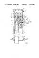
- FIG. 1is a detail cross-sectional view taken on a vertical plane through one form of fill neck assembly embodying the present invention
- FIG. 2is a side elevational view of a second form of fill neck assembly embodying the present invention.
- FIG. 3is a detail cross-sectional view taken on line 3--3 of FIG. 2;
- FIG. 4is a detail cross-sectional view taken on line 4--4 of FIG. 2.
- a fill neck assembly embodying the present inventionincludes a tubular outer housing designated generally 10 which is internally threaded at its upper end as at 12 to threadably receive a closure cap 14 which, when in place, sealingly closes the upper end of housing 10 at an annular seal 16.
- housing 10The interior of housing 10 is formed with an annular upwardly facing radial shoulder 18.
- An inner housing designated generally 20is mounted in the interior of outer housing 10 and is formed with a cup-shaped upper end portion 22 dimensioned to be sealingly seated upon radial shoulder 18 and sealed to the shoulder as by an o-ring 24.
- the bottom wall 26 of the cup-shaped upper portion 22is formed with an inlet passage 28 extending through the wall.
- a resilient annular seal 30is fixedly mounted in the upper end of this passage and is formed with an internal diameter dimensioned to slidably and sealingly receive the tubular fuel dispensing nozzle of a service station pump, these nozzles being made to a standard outer diameter.
- Inner housing 20is formed with a downwardly projecting tubular extension 32 of passage 20 open at its lower end and adapted to be sealingly received upon the upper end of a conduit 34 which extends downwardly into the interior of a vehicle fuel tank partially indicated at 36.
- Conduit 34passes through the interior of a larger diameter conduit 38 which sealingly receives the lower end of main housing 10 in its upper end and opens at its lower end into the interior of fuel tank 36 through a tank seal indicated at 40.
- an internal chamber 42is formed in inner housing 20 which communicates with inlet passage 28, via an opening 44.
- a passage 46 extending from the upper end of chamber 42 through bottom wall 26is normally closed by a valve head 48 biassed downwardly against the top of bottom wall 26 by a spring 50 engaged with a plate 52 fixedly secured to valve head 48.
- a third housing 54is mounted within outer housing 10 to define a passage 56 opening near the bottom of housing 10 and extending upwardly through the housing to communicate at its upper end with a relatively small diameter passage 58 extending upwardly through an internal wall 60 within housing 54.
- the lower portion of passage 56is filled with a loosely packed or coarsely porous material 59 which presents a relatively small resistence to the flow of vapor but presents a greater resistence to the flow of liquid fuel through passage 56.
- a float ball 90rests on the top of material 59.
- a chamber 62is formed within housing 54 above wall 60 and communicates with an outlet passage 64 extending through a hose coupling 66 which projects to the exterior of housing 10 via a sealed bore 68.
- Passage 58is normally closed at its upper end by a valve head 70.
- a valve stem 72is fixedly secured to valve head 70 and projects vertically upwardly through an opening 74 through the top of housing 54.
- the upper end of valve stem 72is formed with a vertically elongate hollow enlarged section 76 which slidably receives a valve actuator 78 which projects upwardly through a sliding seal 80 mounted in an opening 82 through bottom wall 26.
- a head 84 at the upper end of actuator 78is located to be engaged and depressed by closure cap 14 when cap 14 is in the illustrated closed position of FIG. 1.
- Actuator 78is biassed upwardly relative to valve stem 72 by a compression spring 86, while valve stem 72 is in turn resiliently biassed upwardly by a compression spring 88 engaged beneath the enlarged portion 76 of valve stem 72 and the top of housing 54.
- Outlet passage 64is connected via a conduit schematically indicated at 92 directly to a refueling vapor canister 94 which may be vented to atmosphere as by a vent 96.
- a conduit 98connects an outlet of canister 94 to a vapor disposal system schematically indicated at 100 which permits fuel vapor withdrawn from canister 94 to flow to the intake manifold of the vehicle engine for combustion by the engine.
- the system indicated at 100will include a computer controlled purge valve and a regulator valve which act in response to engine operating conditions and manifold pressure to limit the rate of flow of vapor from canister 94 to the engine to a rate low enough to assure combustion of all of the vapor so transferred to the engine.
- the fill neck assembly of FIG. 1typically will be mounted within a well formed in the rear fender of the vehicle, and the mounting means, not shown, preferably will be so designed as to permit reasonable access enabling removal of the fill neck assembly as a unit.
- the first step in the refueling operationis the removal of closure cap 14 from the fill neck assembly. Removal of cap 14 permits actuator 78 to move upwardly relative to the valve stem 72 by extension of compression spring 86, and this release of the downward biassing action of spring 86 against valve stem 72 in turn permits spring 88 to elevate the valve stem, lifting valve head 70 clear of passage 58.
- the fuel dispensing nozzle of the service station pumpis then inserted downwardly through annular seal 30 and fuel dispensed from the nozzle passes downwardly through inlet passage 28, 32 and through the inner conduit 34 into the interior of fuel tank 36.
- the incoming fueldisplace fuel vapor from the head space of the tank upwardly through the passage defined between the inner conduit 34 and outer conduit 38, and this vapor flows upwardly through the flow retarding material 59, through passage 58 into chamber 62 and thence via outlet 64 and conduit 92 to the refueling vapor canister 94.
- the fill neckis formed with a generally tubular housing designated generally 110 formed with separate internal passages 112, 114 adapted to open at their lower ends into inner 34' and outer 38' conduits leading to the vehicle fuel tank in the same manner as the conduits 34 and 38 of the FIG. 1 embodiment.
- a cup-shaped insert 116 fixedly mounted in the upper end of passage 112receives an annular seal 118 in an opening through its bottom wall, the seal 118, as in the embodiment of FIG. 1, being dimensioned to slidably and sealingly receive a standard fuel dispensing nozzle.
- the passage through seal 118is normally closed at its underside by a hinged plate-like trap door valve 119 resiliently biassed to the closed position shown in FIG. 3 as by a torsion spring 120.
- the trap door valve 119is hingedly mounted as by a hinge pin 122 on the underside of insert 116.
- passage 114is filled with some form of loosely packed or coarsely porous material 124 which will present a minimum amount of resistence to flow of vapor, but will present a substantially greater resistence to the flow of liquid fuel.
- a float ball 126rests upon the top of material 124 and is normally spaced below a downwardly facing shoulder 128 in the upper end of passage 114 which opens into a chamber 129 which in turn opens into a somewhat larger chamber 130 communicating with an outlet passage 132 through a hose coupling 134 at the exterior of the fill neck assembly.
- a valve head 136is normally biassed to the closed position shown in FIG. 3 to block fluid communication between chambers 128 and 130 as by a spring 138.
- a valve stem 140is fixedly secured to valve head 136 and projects from head 136 into chamber 128.
- a recess 142 in the left-hand end of stem 140 as viewed in FIG. 3slidably receives one end of a valve actuator 144 mounted for horizontal sliding movement within an internal wall 146 of housing 110.
- the opposite end of actuator 144is formed with a series of rack teeth 148 which are meshed with a pinion gear segment 150 fixedly mounted upon trap door valve 119.
- the right-hand end of valve actuator 144is spaced somewhat at 145 from the bottom of recess 142, this last motion spacing 145 enabling valves 118 and 136 to independently move to their fully closed position.
- a bypass chamber 152is also formed within housing 110.
- Chamber 152can be placed in communication with passage 112, see FIG. 4, via a passage 154 which is normally closed by a spring loaded valve head 156, this arrangement corresponding to the pressure relief valve 48 of the FIG. 1 embodiment.
- Chamber 152opens into insert 116 via a passage 158 through the walls of insert 116 and housing 110.
- outlet passage 132is connected via a conduit coupled to hose coupling 134 to a refueling vapor canister.
- the open upper end of the fill neck assembly of FIGS. 2-4is normally closed by a conventional closure cap, not shown.
- a refueling operationis initiated by inserting a standard fuel dispensing nozzle axially downwardly through annular seal 118. As the nozzle is pushed downwardly through seal 118, the end of the nozzle engages the trap door valve 119, and further downward movement of the nozzle hinges the trap door in a counterclockwise direction about its hinge pin 122 as viewed in FIG. 3.
- the meshed engagement between the pinion gear segment 150 on trap door valve 119 with rack 148 on the actuatortranslates this counterclockwise hinging of trap door valve 119 into rightward movement of valve actuator 144 as viewed in FIG. 3.
- actuator 144has been moved to the right from the FIG. 3 position a lost motion distance sufficient to engage its right-hand end with the bottom of recess 142, further rightward movement of actuator 144 will push valve head 136 to the right as viewed in FIG. 3 to place chambers 128 and 130 in communication with each other.
Landscapes
- Engineering & Computer Science (AREA)
- Life Sciences & Earth Sciences (AREA)
- Sustainable Development (AREA)
- Sustainable Energy (AREA)
- Chemical & Material Sciences (AREA)
- Combustion & Propulsion (AREA)
- Transportation (AREA)
- Mechanical Engineering (AREA)
- Cooling, Air Intake And Gas Exhaust, And Fuel Tank Arrangements In Propulsion Units (AREA)
Abstract
Description
Claims (14)
Priority Applications (1)
| Application Number | Priority Date | Filing Date | Title |
|---|---|---|---|
| US07/109,712US4932444A (en) | 1987-10-19 | 1987-10-19 | Fill neck assembly for vehicle mounted fuel vapor recovery system |
Applications Claiming Priority (1)
| Application Number | Priority Date | Filing Date | Title |
|---|---|---|---|
| US07/109,712US4932444A (en) | 1987-10-19 | 1987-10-19 | Fill neck assembly for vehicle mounted fuel vapor recovery system |
Publications (1)
| Publication Number | Publication Date |
|---|---|
| US4932444Atrue US4932444A (en) | 1990-06-12 |
Family
ID=22329147
Family Applications (1)
| Application Number | Title | Priority Date | Filing Date |
|---|---|---|---|
| US07/109,712Expired - Fee RelatedUS4932444A (en) | 1987-10-19 | 1987-10-19 | Fill neck assembly for vehicle mounted fuel vapor recovery system |
Country Status (1)
| Country | Link |
|---|---|
| US (1) | US4932444A (en) |
Cited By (32)
| Publication number | Priority date | Publication date | Assignee | Title |
|---|---|---|---|---|
| US5071018A (en)* | 1990-09-10 | 1991-12-10 | Ford Motor Company | Capless closure assembly for a fuel filler pipe |
| US5099880A (en)* | 1989-03-24 | 1992-03-31 | Stant Inc. | Fuel tank venting control valve assembly |
| US5103877A (en)* | 1991-04-15 | 1992-04-14 | General Motors Corporation | Vapor-liquid separator for evaporative emissions control system |
| US5186220A (en)* | 1990-07-04 | 1993-02-16 | Blau Kg | Filling nipple for a fuel tank |
| US5259412A (en)* | 1992-08-14 | 1993-11-09 | Tillotson, Ltd. | Fuel tank vapor recovery control |
| US5275213A (en)* | 1993-01-22 | 1994-01-04 | Perko, Inc. | Fuel filling and venting device |
| US5320147A (en)* | 1993-05-06 | 1994-06-14 | Ford Motor Company | Fuel filler pipe fill control module |
| US5404906A (en)* | 1992-12-21 | 1995-04-11 | Nissan Motor Co., Ltd. | Fuel tank |
| US5431199A (en)* | 1993-11-30 | 1995-07-11 | Benjey, Robert P | Redundant seal for vehicle filler neck |
| US5437317A (en)* | 1993-02-04 | 1995-08-01 | Om Corporation | Ventilation line opening/closing means of fuel tank |
| US5503199A (en)* | 1994-03-21 | 1996-04-02 | Attwood Corporation | Fuel fill devices for boats |
| US5507324A (en)* | 1994-03-21 | 1996-04-16 | Attwood Corporation | Fuel fill devices for boats |
| US5595222A (en)* | 1995-07-05 | 1997-01-21 | Ford Motor Company | Positive seal retainer for quick install fuel cap |
| US5606954A (en)* | 1993-12-22 | 1997-03-04 | Honda Giken Kogyo Kabushiki Kaisha | Evaporative fuel processing device |
| US5623964A (en)* | 1995-08-14 | 1997-04-29 | Tsai; Shun-Ching | Safety gas filling valve for vehicles |
| US5630403A (en)* | 1996-06-13 | 1997-05-20 | Siemens Electric Limited | Force-balanced sonic flow emission control valve |
| US6026866A (en)* | 1997-08-11 | 2000-02-22 | Gilbarco Inc. | Onboard vapor recovery detection nozzle |
| US6029697A (en)* | 1998-06-17 | 2000-02-29 | Ebw, Inc. | Air vent for the auto limiter |
| US6065507A (en)* | 1998-03-12 | 2000-05-23 | Gilbarco Inc. | Onboard vapor recovery vehicle fill neck vapor block |
| US6127672A (en)* | 1997-05-23 | 2000-10-03 | Canadian Space Agency | Topological and motion measuring tool |
| US6230739B1 (en)* | 1998-05-07 | 2001-05-15 | Tesma International Inc. | Fuel refilling assembly |
| US6340031B1 (en)* | 1998-06-30 | 2002-01-22 | Honda Giken Kogyo Kabushiki Kaisha | Check valve for refueling pipe of fuel tank |
| US6705481B2 (en) | 1998-03-20 | 2004-03-16 | Temtec Fahrzeutechnick | Actuatable fuel tank closure having guide pipe |
| US20040123846A1 (en)* | 2002-09-10 | 2004-07-01 | Rado Gordon E. | Emissions control system for small internal combustion engines |
| US20050092305A1 (en)* | 2003-10-03 | 2005-05-05 | Rado Gordon E. | Centrifugally operated evaporative emissions control valve system for internal combustion engines |
| US20080011387A1 (en)* | 2006-07-13 | 2008-01-17 | Gm Global Technology Operations, Inc. | Fuel Flow Restriction Plug for Recirculation Pipe |
| US20090174198A1 (en)* | 2007-11-01 | 2009-07-09 | Parson Freddie L | Device for shielding a pressure relief valve from projecting debris |
| US20110290118A1 (en)* | 2010-05-27 | 2011-12-01 | Fuji Jukogyo Kabushiki Kaisha | Vaporized fuel treatment apparatus |
| WO2012126593A2 (en) | 2011-03-23 | 2012-09-27 | Audi Ag | Tank ventilation device for a motor vehicle |
| US20150361928A1 (en)* | 2013-12-04 | 2015-12-17 | Nissan North America, Inc. | Vehicle fuel vapor recovery system |
| US20170292477A1 (en)* | 2014-09-01 | 2017-10-12 | Aisan Kogyo Kabushiki Kaisha | Vaporized fuel processing apparatus |
| US11021361B2 (en)* | 2019-07-02 | 2021-06-01 | Toyoda Gosei Co., Ltd. | Nozzle guide |
Citations (8)
| Publication number | Priority date | Publication date | Assignee | Title |
|---|---|---|---|---|
| US4564054A (en)* | 1983-03-03 | 1986-01-14 | Bengt Gustavsson | Fluid transfer system |
| US4630749A (en)* | 1986-03-18 | 1986-12-23 | General Motors Corporation | Fuel fill tube with vapor vent and overfill protection |
| US4706708A (en)* | 1986-06-23 | 1987-11-17 | General Motors Corporation | Fuel tank venting |
| US4714172A (en)* | 1986-12-23 | 1987-12-22 | Gt Development Corporation | Vapor recovery systems |
| US4715509A (en)* | 1985-07-31 | 1987-12-29 | Toyota Jidosha Kabushiki Kaisha | Fuel filler conduit |
| US4724861A (en)* | 1986-08-18 | 1988-02-16 | General Motors Corporation | Fuel tank venting |
| US4742809A (en)* | 1985-02-23 | 1988-05-10 | Toyota Jidosha Kabushiki Kaisha | Fuel tank |
| US4747508A (en)* | 1987-03-09 | 1988-05-31 | General Motors Corporation | Fuel tank venting |
- 1987
- 1987-10-19USUS07/109,712patent/US4932444A/ennot_activeExpired - Fee Related
Patent Citations (8)
| Publication number | Priority date | Publication date | Assignee | Title |
|---|---|---|---|---|
| US4564054A (en)* | 1983-03-03 | 1986-01-14 | Bengt Gustavsson | Fluid transfer system |
| US4742809A (en)* | 1985-02-23 | 1988-05-10 | Toyota Jidosha Kabushiki Kaisha | Fuel tank |
| US4715509A (en)* | 1985-07-31 | 1987-12-29 | Toyota Jidosha Kabushiki Kaisha | Fuel filler conduit |
| US4630749A (en)* | 1986-03-18 | 1986-12-23 | General Motors Corporation | Fuel fill tube with vapor vent and overfill protection |
| US4706708A (en)* | 1986-06-23 | 1987-11-17 | General Motors Corporation | Fuel tank venting |
| US4724861A (en)* | 1986-08-18 | 1988-02-16 | General Motors Corporation | Fuel tank venting |
| US4714172A (en)* | 1986-12-23 | 1987-12-22 | Gt Development Corporation | Vapor recovery systems |
| US4747508A (en)* | 1987-03-09 | 1988-05-31 | General Motors Corporation | Fuel tank venting |
Cited By (44)
| Publication number | Priority date | Publication date | Assignee | Title |
|---|---|---|---|---|
| US5099880A (en)* | 1989-03-24 | 1992-03-31 | Stant Inc. | Fuel tank venting control valve assembly |
| US5755248A (en)* | 1989-03-24 | 1998-05-26 | Stant Manufacturing, Inc. | Fuel tank venting control valve assembly |
| US5186220A (en)* | 1990-07-04 | 1993-02-16 | Blau Kg | Filling nipple for a fuel tank |
| US5071018A (en)* | 1990-09-10 | 1991-12-10 | Ford Motor Company | Capless closure assembly for a fuel filler pipe |
| US5103877A (en)* | 1991-04-15 | 1992-04-14 | General Motors Corporation | Vapor-liquid separator for evaporative emissions control system |
| US5259412A (en)* | 1992-08-14 | 1993-11-09 | Tillotson, Ltd. | Fuel tank vapor recovery control |
| US5404906A (en)* | 1992-12-21 | 1995-04-11 | Nissan Motor Co., Ltd. | Fuel tank |
| US5275213A (en)* | 1993-01-22 | 1994-01-04 | Perko, Inc. | Fuel filling and venting device |
| US5437317A (en)* | 1993-02-04 | 1995-08-01 | Om Corporation | Ventilation line opening/closing means of fuel tank |
| US5320147A (en)* | 1993-05-06 | 1994-06-14 | Ford Motor Company | Fuel filler pipe fill control module |
| US5431199A (en)* | 1993-11-30 | 1995-07-11 | Benjey, Robert P | Redundant seal for vehicle filler neck |
| US5606954A (en)* | 1993-12-22 | 1997-03-04 | Honda Giken Kogyo Kabushiki Kaisha | Evaporative fuel processing device |
| US5503199A (en)* | 1994-03-21 | 1996-04-02 | Attwood Corporation | Fuel fill devices for boats |
| US5507324A (en)* | 1994-03-21 | 1996-04-16 | Attwood Corporation | Fuel fill devices for boats |
| US5595222A (en)* | 1995-07-05 | 1997-01-21 | Ford Motor Company | Positive seal retainer for quick install fuel cap |
| US5638874A (en)* | 1995-07-05 | 1997-06-17 | Ford Motor Company | Positive seal retainer for quick install fuel cap |
| US5623964A (en)* | 1995-08-14 | 1997-04-29 | Tsai; Shun-Ching | Safety gas filling valve for vehicles |
| US5630403A (en)* | 1996-06-13 | 1997-05-20 | Siemens Electric Limited | Force-balanced sonic flow emission control valve |
| US6127672A (en)* | 1997-05-23 | 2000-10-03 | Canadian Space Agency | Topological and motion measuring tool |
| US6026866A (en)* | 1997-08-11 | 2000-02-22 | Gilbarco Inc. | Onboard vapor recovery detection nozzle |
| US6065507A (en)* | 1998-03-12 | 2000-05-23 | Gilbarco Inc. | Onboard vapor recovery vehicle fill neck vapor block |
| US6705481B2 (en) | 1998-03-20 | 2004-03-16 | Temtec Fahrzeutechnick | Actuatable fuel tank closure having guide pipe |
| US6230739B1 (en)* | 1998-05-07 | 2001-05-15 | Tesma International Inc. | Fuel refilling assembly |
| US6029697A (en)* | 1998-06-17 | 2000-02-29 | Ebw, Inc. | Air vent for the auto limiter |
| US6340031B1 (en)* | 1998-06-30 | 2002-01-22 | Honda Giken Kogyo Kabushiki Kaisha | Check valve for refueling pipe of fuel tank |
| US20040123846A1 (en)* | 2002-09-10 | 2004-07-01 | Rado Gordon E. | Emissions control system for small internal combustion engines |
| US7131430B2 (en) | 2002-09-10 | 2006-11-07 | Tecumseh Products Company | Emissions control system for small internal combustion engines |
| US20070079814A1 (en)* | 2002-09-10 | 2007-04-12 | Tecumseh Products Company | Emissions control system for small internal combustion engines |
| US20050092305A1 (en)* | 2003-10-03 | 2005-05-05 | Rado Gordon E. | Centrifugally operated evaporative emissions control valve system for internal combustion engines |
| US7047951B2 (en) | 2003-10-03 | 2006-05-23 | Tecumseh Products Company | Centrifugally operated evaporative emissions control valve system for internal combustion engines |
| US20080011387A1 (en)* | 2006-07-13 | 2008-01-17 | Gm Global Technology Operations, Inc. | Fuel Flow Restriction Plug for Recirculation Pipe |
| US7614431B2 (en)* | 2006-07-13 | 2009-11-10 | Gm Global Technology Operations, Inc. | Fuel flow restriction plug for recirculation pipe |
| US20090174198A1 (en)* | 2007-11-01 | 2009-07-09 | Parson Freddie L | Device for shielding a pressure relief valve from projecting debris |
| US20110290118A1 (en)* | 2010-05-27 | 2011-12-01 | Fuji Jukogyo Kabushiki Kaisha | Vaporized fuel treatment apparatus |
| US8551231B2 (en)* | 2010-05-27 | 2013-10-08 | Fuji Jukogyo Kabushiki Kaisha | Vaporized fuel treatment apparatus |
| WO2012126593A2 (en) | 2011-03-23 | 2012-09-27 | Audi Ag | Tank ventilation device for a motor vehicle |
| DE102011014713A1 (en) | 2011-03-23 | 2012-09-27 | Audi Ag | Tank ventilation device for a motor vehicle |
| DE102011014713B4 (en)* | 2011-03-23 | 2016-05-19 | Audi Ag | Tank ventilation device for a motor vehicle |
| US9592730B2 (en) | 2011-03-23 | 2017-03-14 | Audi Ag | Tank ventilation device for a motor vehicle |
| US20150361928A1 (en)* | 2013-12-04 | 2015-12-17 | Nissan North America, Inc. | Vehicle fuel vapor recovery system |
| US9803595B2 (en)* | 2013-12-04 | 2017-10-31 | Nissan North America, Inc. | Vehicle fuel vapor recovery system |
| US20170292477A1 (en)* | 2014-09-01 | 2017-10-12 | Aisan Kogyo Kabushiki Kaisha | Vaporized fuel processing apparatus |
| US9976520B2 (en)* | 2014-09-01 | 2018-05-22 | Aisan Kogyo Kabushiki Kaisha | Vaporized fuel processing apparatus |
| US11021361B2 (en)* | 2019-07-02 | 2021-06-01 | Toyoda Gosei Co., Ltd. | Nozzle guide |
Similar Documents
| Publication | Publication Date | Title |
|---|---|---|
| US4932444A (en) | Fill neck assembly for vehicle mounted fuel vapor recovery system | |
| US4887578A (en) | On board refueling vapor recovery system | |
| US4809863A (en) | Fill neck assembly for on board refueling vapor recovery system | |
| US5755248A (en) | Fuel tank venting control valve assembly | |
| KR100243522B1 (en) | Evaporative Gas Recovery Fuel Tank System | |
| US5282497A (en) | Fuel delivery and vapor control system for controlling the release of fuel vapors from a vehicle fuel tank | |
| US5592963A (en) | Control valve and system for fuel vapor recovery | |
| US5960817A (en) | Control valve and system for fuel vapor recovery | |
| US7823610B2 (en) | Refueling shut-off system with fill-limit vent valve | |
| US5054528A (en) | Venting device of a fuel tank for a motor vehicle | |
| US5056570A (en) | Capless vehicle refueling system | |
| US6675779B2 (en) | Dual float valve for fuel tank vent with liquid carryover filter | |
| US4630749A (en) | Fuel fill tube with vapor vent and overfill protection | |
| US4770677A (en) | Vapor recovery system | |
| CA1079239A (en) | Interlock system for a gasoline dispensing nozzle | |
| US5103877A (en) | Vapor-liquid separator for evaporative emissions control system | |
| US5647334A (en) | Fuel vapor recovery system control valve | |
| US4821908A (en) | On-board refueling vapor recovery system | |
| US6848463B2 (en) | Vapor vent valve | |
| US6145532A (en) | Fuel tank fill level control and vapor venting valve | |
| US5579802A (en) | Fuel tank vapor control apparatus | |
| KR101289910B1 (en) | Controlling vapor emission in a small engine fuel tank system | |
| US4796593A (en) | Tank mounted valve for fuel vapor recovery system | |
| US4062384A (en) | Vapor recovery adapter for gasoline-dispensing nozzles | |
| US7055556B2 (en) | Controlling vapor recirculation during refueling of a tank through a filler tube from a dispensing nozzle |
Legal Events
| Date | Code | Title | Description |
|---|---|---|---|
| AS | Assignment | Owner name:COLT INDUSTRIES INC (FORMERLY COLT INDUSTRIES OPER Free format text:ASSIGNMENT OF ASSIGNORS INTEREST.;ASSIGNOR:MICEK, DENNIS;REEL/FRAME:005243/0610 Effective date:19871015 | |
| AS | Assignment | Owner name:COLTEC INDUSTRIES, INC. Free format text:CHANGE OF NAME;ASSIGNOR:COLT INDUSTRIES INC.;REEL/FRAME:006144/0197 Effective date:19900503 | |
| AS | Assignment | Owner name:BANKERS TRUST COMPANY, NEW YORK Free format text:SECURITY INTEREST;ASSIGNOR:COLTEC INDUSTRIES INC.;REEL/FRAME:006080/0224 Effective date:19920401 | |
| FPAY | Fee payment | Year of fee payment:4 | |
| AS | Assignment | Owner name:BORG-WARNER AUTOMOTIVE, INC., A CORP. OF DELAWARE, Free format text:ASSIGNMENT OF ASSIGNORS INTEREST;ASSIGNOR:COLTEC INDUSTRIES INC., A CORP. OF PENNSYLVANIA;REEL/FRAME:008246/0989 Effective date:19960617 | |
| FPAY | Fee payment | Year of fee payment:8 | |
| REMI | Maintenance fee reminder mailed | ||
| LAPS | Lapse for failure to pay maintenance fees | ||
| STCH | Information on status: patent discontinuation | Free format text:PATENT EXPIRED DUE TO NONPAYMENT OF MAINTENANCE FEES UNDER 37 CFR 1.362 | |
| FP | Lapsed due to failure to pay maintenance fee | Effective date:20020612 |