US4932353A - Chemical coating apparatus - Google Patents
Chemical coating apparatusDownload PDFInfo
- Publication number
- US4932353A US4932353AUS07/279,721US27972188AUS4932353AUS 4932353 AUS4932353 AUS 4932353AUS 27972188 AUS27972188 AUS 27972188AUS 4932353 AUS4932353 AUS 4932353A
- Authority
- US
- United States
- Prior art keywords
- chemical
- pipe
- heat exchanging
- temperature
- heat exchanger
- Prior art date
- Legal status (The legal status is an assumption and is not a legal conclusion. Google has not performed a legal analysis and makes no representation as to the accuracy of the status listed.)
- Expired - Fee Related
Links
Images

Classifications
- B—PERFORMING OPERATIONS; TRANSPORTING
- B05—SPRAYING OR ATOMISING IN GENERAL; APPLYING FLUENT MATERIALS TO SURFACES, IN GENERAL
- B05C—APPARATUS FOR APPLYING FLUENT MATERIALS TO SURFACES, IN GENERAL
- B05C11/00—Component parts, details or accessories not specifically provided for in groups B05C1/00 - B05C9/00
- B05C11/10—Storage, supply or control of liquid or other fluent material; Recovery of excess liquid or other fluent material
- B05C11/1042—Storage, supply or control of liquid or other fluent material; Recovery of excess liquid or other fluent material provided with means for heating or cooling the liquid or other fluent material in the supplying means upstream of the applying apparatus
- B—PERFORMING OPERATIONS; TRANSPORTING
- B05—SPRAYING OR ATOMISING IN GENERAL; APPLYING FLUENT MATERIALS TO SURFACES, IN GENERAL
- B05C—APPARATUS FOR APPLYING FLUENT MATERIALS TO SURFACES, IN GENERAL
- B05C11/00—Component parts, details or accessories not specifically provided for in groups B05C1/00 - B05C9/00
- B05C11/02—Apparatus for spreading or distributing liquids or other fluent materials already applied to a surface ; Controlling means therefor; Control of the thickness of a coating by spreading or distributing liquids or other fluent materials already applied to the coated surface
- B05C11/08—Spreading liquid or other fluent material by manipulating the work, e.g. tilting
Definitions
- the present inventionrelates to a chemical coating apparatus which has a chemical pipe through which a chemical flows, and a heat exchanger disposed along at least part of the chemical pipe and in which the temperature of the chemical is adjusted to a predetermined value by the heat exchanger.
- a chemical coating apparatus of this typeis used in various forms. It is known, for example, as a resist coater which is used to apply a resist on the surface of a semiconductor wafer during the process of manufacturing semiconductor devices.
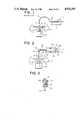
- FIG. 1shows the arrangement of such a known resist coater.
- a semiconductor wafer 3is attached by means of vacuum to a rotary chuck 2 disposed in a cup 1, a coating is applied by dropping resist liquid 5 onto the semiconductor wafer 3 while the wafer 3 is being rotated by the operation of a chuck rotating motor 4.
- the resist liquid 5 applied to the semiconductor wafer 3is supplied by a resist liquid supply device (not shown), and is then subjected to indirect exchange of heat in a heat exchanger 6 through which constant-temperature water 7 having an adjusted temperature circulates, thereby adjusting the temperature of the resist liquid 5. After the resist has had its temperature adjusted in this way, it flows through a chemical pipe 9, such as a Teflon tube, and is then discharged from a chemical nozzle 8 to coat the semiconductor wafer 3.
- a chemical pipe 9such as a Teflon tube
- the thickness of a resist film applied to the semiconductor wafer 3tends to vary to a great extent. It is therefore difficult to control the thickness of the resist film, resulting in various problems.
- the film thicknessmay vary within the surface of a single semiconductor wafer, and it may also vary among a plurality of wafers.
- the present inventionhas been accomplished to prevent the above-described problems. It is an object of the present invention to provide a chemical coating apparatus, such as a resist coater, which is capable of adjusting the temperature of the chemical, such as the resist, along its path of travel from a source to and including the discharge and which is thus capable of forming a film with a uniform thickness on the surface of an object, such as a semiconductor wafer.
- a chemical coating apparatussuch as a resist coater
- Another object of the present inventionis to provide a chemical coating apparatus which is capable of positively adjusting the temperature of the chemical to a predetermined value in spite of the fact that the chemical, such as a resist liquid, which is to be supplied to the surface of a semiconductor wafer, is influenced by the temperature of external air surrounding the chemical pipe.
- a chemical coating apparatuscomprises: a pipe having one end connected to means for supplying a chemical and the other end positioned opposite an object to be coated with the chemical for transporting the chemical chemical; a nozzle connected to the other end of the pipe for dropping the chemical to the surface of the object to be coated; a main heat exchanger disposed along at least part of the pipe for effecting exchange of heat with the chemical; and an auxiliary heat exchanger disposed between the main heat exchanger and the surrounding nozzle the part of the pipe that extends therebetween for effecting exchange of heat with the chemical.
- a coating apparatuscomprises: a chemical pipe having one end connected to means for supplying a chemical and the other end positioned opposite an object to be coated with the chemical for transporting the chemical; a nozzle connected to the other end of the pipe for dropping the chemical to the surface of the object to be coated; and a heat exchanger disposed along the pipe for adjusting the temperature of the chemical to a predetermined value by the flow of constant-temperature water through the best exchanger, the heat exchanger comprising a first heat exchanging pipe and a second heat exchanging pipe, the first heat exchanging pipe being disposed generally parallel to the pipe, and having one end connected to constant-temperature water circulating means and the other end disposed in and opening in the vicinity of the nozzle disposed at the other end of the pipe for the flow of constant-temperature therethrough, and the second heat exchanging pipe being disposed surrounding the first heat exchanging pipe and the pipe, and communicating with the end of the first heat exchanging pipe opening in the vicinity of the nozzle for the flow of constant-temperature water
- FIG. 1is a view schematically illustrating a known resist coater
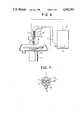
- FIG. 2is a sectional view schematically illustrating a resist coater in accordance with a first embodiment of the present invention
- FIG. 3is an enlarged sectional view of the part of the resist coater shown in FIG. 2 which is encircled by the broken line III in FIG. 2;
- FIG. 4is a sectional view schematically illustrating a resist coater in accordance with a second embodiment of the present invention.
- FIG. 5is a cross-sectional view of a heat exchanger shown in FIG. 4 taken along the line V--V shown in FIG. 4;
- FIG. 6is a sectional view schematically illustrating a resist coater in accordance with a third embodiment of the present invention.
- FIG. 7is a cross-sectional view taken along the line VII--VII shown in FIG. 6.
- FIG. 2shows the arrangement of a chemical coating apparatus in accordance with a first embodiment of the present invention.
- the apparatushas a pipe 9 through which a chemical 5, such as resist liquid, flows, and a nozzle 8 connected to the pipe 9.
- a main heat exchanger 10is disposed in correspondence with at least a portion of the pipe 9, and is provided for effecting exchange of heat with the resist liquid 5.
- the interior of the main heat exchanger 10is supplied with constant-temperature water 7 by a constant-temperature water circulating means (not shown) to enable adequate contact between the constant-temperature water 7 and the portion of the pipe 9 within heat exchanger 10.
- the main heat exchanger 10has a conduit 10a provided with a constant-temperature water inlet 10c, and a jacket 10b disposed surrounding the conduit 10a and a portion of the chemical pipe 9, and provided with a constant-temperature water outlet 10d through which the constant-temperature water 7 is returned to the circulating means.
- An auxiliary heat exchanger 11is disposed along a part of the pipe 9 that extends from the main heat exchanger 10 to the nozzle 8 for effecting exchange of heat with the resist liquid 5.
- the auxiliary heat exchanger 11has first and second heat exchanging pipes 11a and 11b.
- the first heat exchanging pipe 11ais connected to the conduit 10a to supply the constant-temperature water 7 through the conduit 10a is deposed generally parallel to that part of the pipe 9, and is provided with an end 11c opening in the vicinity of the nozzle 8.
- the second heat exchanging pipe 11bis disposed between the main heat exchanger 10 and the nozzle 8 surrounding the first heat exchanging pipe 11a and part of the pipe 9, in communication with the opening end 11c of the first heat exchanging pipe 11a and with the jacket 10b of the main heat exchanger 10 for the flow of the constant-temperature water 7 therethrough.
- the resist liquid 5is subjected to temperature adjustment by the main and auxiliary heat exchangers 10 and 11 along the transport path the resist liquid 5 from its source the nozzle 8.
- Resist liquid 5, which is to be applied to a semiconductor wafer 3is supplied from a resist supply device (not shown) to that portion of the pipe 9, such as a Teflon pipe, disposed in the main heat exchanger 10.
- the resist liquid 5is subjected to indirect exchange of heat in the heat exchanger 10 through which the constant-temperature water 7 at an adjusted temperature flows. Thereby, the temperature of the resist is adjusted.
- the constant-temperature water 7is further sent to a point very close to the nozzle 8 by flowing in the auxiliary heat exchanger 11.
- the constant-temperature water 7 flowing in the heat exchanger 11exchanges heat with the resist liquid 5 flowing in the Teflon tube 9. After exchange of heat, the constant-temperature water 7 is returned to the main heat exchanger 10.
- a single Teflon tubeis used to supply resist liquid to the nozzle 8.
- the apparatusmay alternatively use two or more Teflon tubes.
- the auxiliary heat exchanger 11is provided to enable the adjustment of the temperature of the resist liquid 5 including at the nozzle, thereby enabling control over the temperature of the resist liquid 5. Consequently, it is possible to prevent variation in film thickness within the surface of a single semiconductor wafer and among a plurality of wafers, thereby enhancing the uniformity of film thicknesses.
- FIG. 4illustrates a second embodiment of the present invention.
- a resist coater illustrated therehas a rotary chuck 2 supporting a semiconductor wafer 3 attached thereto by means of vacuum, a rotary shaft 4a supporting the rotary chuck 2, a motor 4 for driving the rotary shaft 4a, a spin cup 1 surrounding the semiconductor wafer 3 and the chuck 2, and a resist liquid nozzle 8 disposed at the tip of a resist liquid supply pipe 9 and positioned above the rotary chuck 2.
- resist liquid 5serving as a chemical
- the resist liquid nozzle 8serving as a chemical
- the resist liquid nozzle 8is dropped from the resist liquid nozzle 8 to the surface of the semiconductor wafer 3 while the rotary chuck 2 is kept stationary or is being rotated at a low speed by the motor 4.
- the resist 5is spread over the entire surface of the semiconductor wafer 3 by centrifugal force generated by the rotation of the rotary chuck 2 at a high speed, thereby forming a resist film, desirably, with a uniform thickness.
- the apparatus in accordance with this embodiment of the present inventionis provided with a heat exchanger 12.
- the heat exchanger 12has a predetermined length and a cross-sectional structure as shown in FIG. 5, and extends substantially the entire length of the resist liquid supply pipe 9 through which the resist liquid 5 flows from a resist liquid supply device (not shown) to the resist liquid nozzle 8. Further, the apparatus has an arrangement in which the temperature of the resist liquid 5 is adjusted to a predetermined set temperature, indirectly by constant-temperature water 7 which flows in opposite direction streams within the heat exchanger 12.
- the heat exchanger 12comprises a constant-temperature water supply pipe 13 disposed in close contact and parallel to the resist liquid supply pipe 9, and a constant-temperature water discharge pipe 14 disposed surrounding the pipe 13 and the resist liquid supply pipe 9.
- the constant-temperature water supply pipe 13 and the constant-temperature water discharge pipe 14are connected to and communicate with a constant-temperature water circulating means 15 disposed outside the resist coater.
- constant-temperature water 7is supplied from the constant-temperature water circulating means 15 to the constant-temperature water supply pipe 13, flows in the pipe 13 to reach an opening end 13a of the pipe 13 where it changes its direction and flows into the constant-temperature water discharge pipe 14 to be returned to the circulating means 15.
- the constant-temperature water circulating means 15has a controller (not shown) provided therein for adjusting the temperature of constant-temperature water 7 to a predetermined set temperature.
- a temperature sensor 16is disposed at a supply port of the circulating means 15, and the temperature of the constant-temperature water 7 is controlled on the basis of the difference between the actual temperature of the water 7, which is detected by the sensor 16, and a pre-established temperature.
- the above-described second embodimentachieves, if the apparatus is used to apply a chemical coating to an object (e.g., the semiconductor wafer 3), uniform thickness of chemical films applied to semiconductor wafers.
- FIG. 6illustrates a third embodiment of the present invention.
- the basic arrangement and operation of the resist coateris the same as that in the second embodiment, except that the heat exchanger 12 is provided with a temperature detecting means 20 comprising a temperature measuring resistor. Therefore, in FIGS. 6 and 7, the same reference numerals as those in FIGS. 4 and 5 are used to indicate members which are the same as or correspond to those in the second embodiment, and detailed explanations of these members will be omitted.
- a resist coater in accordance with this embodimenthas a resist liquid supply pipe 9 for supplying resist liquid 5 to a nozzle 8, and a heat exchanger 12 of a predetermined length which is disposed along the pipe 9.
- the heat exchanger 12comprises a constant-temperature water supply pipe 13 disposed in close contact and in parallel with the resist liquid supply pipe 9, and a constant-temperature water discharge pipe 14 disposed surrounding the pipe 13 and the resist liquid supply pipe 9.
- Each of these pipes 13 and 14is connected to and communicates with a constant-temperature water circulating means 15 disposed outside of the resist coater.
- a temperature detecting meanssuch as a temperature measuring resistor 20, is provided at an opening end 13a of the constant-temperature water supply pipe 13, at which constant-temperature water 7 which has been supplied from the circulating means 15 to the constant-temperature water supply pipe 13 flows out from the pipe 13, changes its direction of flow, and flows into the constant-temperature water discharge pipe 14. More specifically, the temperature measuring resistor 20 is provided inside the constant-temperature water discharge pipe 14 at a position in the vicinity of the point where the water 7 changes its direction of flow to detect the temperature of the constant-temperature water 7 at this point of flow direction change.
- the temperature of the water 7is detected by the temperature measuring resistor 20 after the water 7 has completed exchange of heat with the resist liquid 5 flowing through the pipe 9 been subjected to the air near the end of pipe 9.
- the constant-temperature water circulating means 15has a controller (not shown) which controls the temperature of the water 7 on the basis of the thus detected actual temperature of the water 7.
- Constant temperature water 7 having had its temperature adjusted to a set temperatureis supplied from the circulating means 15 to the supply pipe 13. Accordingly, the temperature of the resist liquid 5 which is to be dropped onto the surface of a semiconductor wafer 3 is adjusted by the constant-temperature water 7 whose temperature has been adjusted taking into consideration the influence of the external air surrounding the tip of the pipe 9. Therefore, the temperature of the resist liquid 5, which is adjusted by the constant-temperature water 7 that has had its temperature adjusted in this way, is kept from greatly deviating from the set temperature, thus achieving very precise temperature adjustment.
- the temperature measuring resistor 20provided at a position in the vicinity of the point where the water 7 changes its direction of flow, that is, at a position in the vicinity of the opening end 13a of the constant-temperature water supply pipe 13, it is possible to detect the actual temperature of the water 7 after it has substantially completed exchange of heat with the 5 flowing through the chemical pipe 9 and has been subjected to the peripheral air temperature.
- the thus detected actual temperature of the water 7provides an indirect measure of the actual temperature of the chemical 5.
- the controller of the constant-temperature water circulating means 15when the temperature of the water 7 is controlled by the controller of the constant-temperature water circulating means 15 on the basis of the difference of the actual temperature detected by the temperature measuring resistor 20 and a pre-established temperature, it is possible to supply constant-temperature water 7, having a temperature that has been adjusted to the pre-established temperature, to the heat exchanger 12. This feature is effective to prevent the temperature of the chemical 5 from deviating from the pre-established temperature after the chemical temperature has been adjusted by the constant-temperature water 7.
- the resist coateris capable of positively adjusting the temperature of the resist liquid 5, which is to be supplied to the surface of a semiconductor wafer 3, to a predetermined temperature, thereby preventing variation in the thickness of the resist films caused by the peripheral air temperature, and thereby enabling resist films which are uniform in thickness to be formed on the surface of semiconductor wafers.
- the present inventionis applied to resist coaters, the present invention is not limited thereto. It may alternatively be applied to an apparatus requiring the adjustment of the temperature of a chemical, such as a developing apparatus.
Landscapes
- Exposure Of Semiconductors, Excluding Electron Or Ion Beam Exposure (AREA)
- Coating Apparatus (AREA)
Abstract
Description
Claims (8)
Applications Claiming Priority (4)
| Application Number | Priority Date | Filing Date | Title |
|---|---|---|---|
| JP62-193235[U] | 1987-12-18 | ||
| JP19323587UJPH0195728U (en) | 1987-12-18 | 1987-12-18 | |
| JP3991588AJPH01214022A (en) | 1988-02-22 | 1988-02-22 | Apparatus for adjusting temperature of chemical liquid |
| JP63-39915 | 1988-02-22 |
Publications (1)
| Publication Number | Publication Date |
|---|---|
| US4932353Atrue US4932353A (en) | 1990-06-12 |
Family
ID=26379316
Family Applications (1)
| Application Number | Title | Priority Date | Filing Date |
|---|---|---|---|
| US07/279,721Expired - Fee RelatedUS4932353A (en) | 1987-12-18 | 1988-12-05 | Chemical coating apparatus |
Country Status (1)
| Country | Link |
|---|---|
| US (1) | US4932353A (en) |
Cited By (46)
| Publication number | Priority date | Publication date | Assignee | Title |
|---|---|---|---|---|
| US5089305A (en)* | 1988-05-27 | 1992-02-18 | Tokyo Electron Limited | Coating apparatus and method for applying a liquid to a semiconductor wafer including selecting a nozzle on a stand by state |
| US5127362A (en)* | 1989-05-22 | 1992-07-07 | Tokyo Electron Limited | Liquid coating device |
| US5219145A (en)* | 1991-09-12 | 1993-06-15 | Unisys Corporation | Adjustably deflectable spring plate device |
| US5374312A (en)* | 1991-01-23 | 1994-12-20 | Tokyo Electron Limited | Liquid coating system |
| US5540774A (en)* | 1992-10-19 | 1996-07-30 | Illinois Tool Works Inc. | Drip proof dispensing method and nozzle assembly for dispensing viscous materials |
| US5658387A (en)* | 1991-03-06 | 1997-08-19 | Semitool, Inc. | Semiconductor processing spray coating apparatus |
| US5670210A (en)* | 1994-10-27 | 1997-09-23 | Silicon Valley Group, Inc. | Method of uniformly coating a substrate |
| WO1997040948A1 (en)* | 1996-05-01 | 1997-11-06 | Kellogg Company | Apparatus for depositing a viscous fluid material |
| US5863338A (en)* | 1992-11-27 | 1999-01-26 | Matsushita Electric Industrial Co., Ltd. | Apparatus and method for forming thin film |
| US6202656B1 (en)* | 1998-03-03 | 2001-03-20 | Applied Materials, Inc. | Uniform heat trace and secondary containment for delivery lines for processing system |
| US20020004100A1 (en)* | 1994-10-27 | 2002-01-10 | Emir Gurer | Method of uniformly coating a substrate |
| US20020038629A1 (en)* | 1990-05-18 | 2002-04-04 | Reardon Timothy J. | Semiconductor processing spray coating apparatus |
| US6374769B1 (en)* | 1998-09-17 | 2002-04-23 | Fort James Corporation | Fluid material application system employing tube-in-hose heat exchanger |
| US6423139B1 (en)* | 1997-09-16 | 2002-07-23 | Tokyo Ohka Kogyo Co., Ltd. | Chemical liquid treatment apparatus |
| DE10118631A1 (en)* | 2001-04-12 | 2002-10-17 | Voith Paper Patent Gmbh | Paper machine paste application jet has temperature regulation channels incorporated in parallel lips |
| US6599560B1 (en) | 1997-10-30 | 2003-07-29 | Fsi International, Inc. | Liquid coating device with barometric pressure compensation |
| US20040072450A1 (en)* | 2002-10-15 | 2004-04-15 | Collins Jimmy D. | Spin-coating methods and apparatuses for spin-coating, including pressure sensor |
| US20050008766A1 (en)* | 2003-06-18 | 2005-01-13 | Seiko Epson Corporation | Liquid applying device, method for applying liquid, method for manufacturing liquid crystal device, and electronic equipment |
| US20050214462A1 (en)* | 2000-12-29 | 2005-09-29 | Toshiyuki Kaeriyama | Micromechanical device recoat methods |
| US20050273161A1 (en)* | 2002-11-26 | 2005-12-08 | Advanced Cardiovascular Systems, Inc. | Electrostatic loading of drugs on implantable medical devices |
| US7018943B2 (en) | 1994-10-27 | 2006-03-28 | Asml Holding N.V. | Method of uniformly coating a substrate |
| US7030039B2 (en) | 1994-10-27 | 2006-04-18 | Asml Holding N.V. | Method of uniformly coating a substrate |
| US7077860B2 (en) | 1997-04-24 | 2006-07-18 | Advanced Cardiovascular Systems, Inc. | Method of reducing or eliminating thrombus formation |
| US7087115B1 (en) | 2003-02-13 | 2006-08-08 | Advanced Cardiovascular Systems, Inc. | Nozzle and method for use in coating a stent |
| US20060236926A1 (en)* | 2005-03-30 | 2006-10-26 | Kabushiki Kaisha Toshiba | Semiconductor manufacturing apparatus |
| US7198675B2 (en) | 2003-09-30 | 2007-04-03 | Advanced Cardiovascular Systems | Stent mandrel fixture and method for selectively coating surfaces of a stent |
| US7258891B2 (en) | 2001-06-28 | 2007-08-21 | Advanced Cardiovascular Systems, Inc. | Stent mounting assembly and a method of using the same to coat a stent |
| US20070221126A1 (en)* | 2004-03-23 | 2007-09-27 | Koganei Corporation | Chemical Liquid Supply Apparatus |
| US7297159B2 (en) | 2000-10-26 | 2007-11-20 | Advanced Cardiovascular Systems, Inc. | Selective coating of medical devices |
| US7338557B1 (en) | 2002-12-17 | 2008-03-04 | Advanced Cardiovascular Systems, Inc. | Nozzle for use in coating a stent |
| US7404681B1 (en) | 2000-05-31 | 2008-07-29 | Fsi International, Inc. | Coating methods and apparatus for coating |
| US7553377B1 (en) | 2004-04-27 | 2009-06-30 | Advanced Cardiovascular Systems, Inc. | Apparatus and method for electrostatic coating of an abluminal stent surface |
| US7563324B1 (en) | 2003-12-29 | 2009-07-21 | Advanced Cardiovascular Systems Inc. | System and method for coating an implantable medical device |
| US7632307B2 (en) | 2004-12-16 | 2009-12-15 | Advanced Cardiovascular Systems, Inc. | Abluminal, multilayer coating constructs for drug-delivery stents |
| US20100133355A1 (en)* | 2008-11-28 | 2010-06-03 | Semes Co., Ltd. | Unit for supplying treating liquid, and apparatus and method for treating substrate using the same |
| US7763308B2 (en) | 2001-09-27 | 2010-07-27 | Advanced Cardiovascular Systems, Inc. | Method of regulating temperature of a composition for coating implantable medical devices |
| US7867547B2 (en) | 2005-12-19 | 2011-01-11 | Advanced Cardiovascular Systems, Inc. | Selectively coating luminal surfaces of stents |
| US8003156B2 (en) | 2006-05-04 | 2011-08-23 | Advanced Cardiovascular Systems, Inc. | Rotatable support elements for stents |
| US8017237B2 (en) | 2006-06-23 | 2011-09-13 | Abbott Cardiovascular Systems, Inc. | Nanoshells on polymers |
| US8048441B2 (en) | 2007-06-25 | 2011-11-01 | Abbott Cardiovascular Systems, Inc. | Nanobead releasing medical devices |
| US8048448B2 (en) | 2006-06-15 | 2011-11-01 | Abbott Cardiovascular Systems Inc. | Nanoshells for drug delivery |
| US8603530B2 (en) | 2006-06-14 | 2013-12-10 | Abbott Cardiovascular Systems Inc. | Nanoshell therapy |
| JP2014063807A (en)* | 2012-09-20 | 2014-04-10 | Hoya Corp | Resist liquid supply device, resist application device, method for managing resist liquid temperature, resist liquid storage device, and method for manufacturing mask blank |
| CN104138824A (en)* | 2013-05-10 | 2014-11-12 | 英飞凌科技股份有限公司 | Application of fluids to substrates |
| WO2015067357A1 (en)* | 2013-11-06 | 2015-05-14 | Dürr Systems GmbH | Application system for applying a coating agent |
| US20230073867A1 (en)* | 2021-09-08 | 2023-03-09 | Semes Co., Ltd. | Apparatus for supplying liquid and apparatus for treating substrate |
Citations (12)
| Publication number | Priority date | Publication date | Assignee | Title |
|---|---|---|---|---|
| GB700728A (en)* | 1950-12-20 | 1953-12-09 | American Cyanamid Co | Improvements relating to heating arrangements for spinneret headings |
| US2676843A (en)* | 1952-08-30 | 1954-04-27 | Fansteel Metallurgical Corp | Spray gun |
| US2779690A (en)* | 1950-06-30 | 1957-01-29 | Libbey Owens Ford Glass Co | Method and apparatus for forming surface films |
| US3000759A (en)* | 1951-10-09 | 1961-09-19 | Barsky George | Method of forming plastisol gaskets on metal members |
| US3445262A (en)* | 1965-04-01 | 1969-05-20 | American Flange & Mfg | Method for lining container closures |
| US3677471A (en)* | 1971-03-01 | 1972-07-18 | Sealectro Corp | Apparatus and process thereof for coating with polytetrafluoroethylene and other materials |
| JPS5982975A (en)* | 1982-11-02 | 1984-05-14 | Nec Corp | Coater for semiconductor substrate |
| JPS60100434A (en)* | 1983-11-05 | 1985-06-04 | Mitsubishi Electric Corp | Insulating coating processing equipment for semiconductor substrates |
| US4675140A (en)* | 1984-05-18 | 1987-06-23 | Washington University Technology Associates | Method for coating particles or liquid droplets |
| JPS62214621A (en)* | 1986-03-17 | 1987-09-21 | Hitachi Ltd | Coating device |
| JPS62279632A (en)* | 1986-05-28 | 1987-12-04 | Nec Corp | Semiconductor manufacturing apparatus |
| US4827867A (en)* | 1985-11-28 | 1989-05-09 | Daikin Industries, Ltd. | Resist developing apparatus |
- 1988
- 1988-12-05USUS07/279,721patent/US4932353A/ennot_activeExpired - Fee Related
Patent Citations (12)
| Publication number | Priority date | Publication date | Assignee | Title |
|---|---|---|---|---|
| US2779690A (en)* | 1950-06-30 | 1957-01-29 | Libbey Owens Ford Glass Co | Method and apparatus for forming surface films |
| GB700728A (en)* | 1950-12-20 | 1953-12-09 | American Cyanamid Co | Improvements relating to heating arrangements for spinneret headings |
| US3000759A (en)* | 1951-10-09 | 1961-09-19 | Barsky George | Method of forming plastisol gaskets on metal members |
| US2676843A (en)* | 1952-08-30 | 1954-04-27 | Fansteel Metallurgical Corp | Spray gun |
| US3445262A (en)* | 1965-04-01 | 1969-05-20 | American Flange & Mfg | Method for lining container closures |
| US3677471A (en)* | 1971-03-01 | 1972-07-18 | Sealectro Corp | Apparatus and process thereof for coating with polytetrafluoroethylene and other materials |
| JPS5982975A (en)* | 1982-11-02 | 1984-05-14 | Nec Corp | Coater for semiconductor substrate |
| JPS60100434A (en)* | 1983-11-05 | 1985-06-04 | Mitsubishi Electric Corp | Insulating coating processing equipment for semiconductor substrates |
| US4675140A (en)* | 1984-05-18 | 1987-06-23 | Washington University Technology Associates | Method for coating particles or liquid droplets |
| US4827867A (en)* | 1985-11-28 | 1989-05-09 | Daikin Industries, Ltd. | Resist developing apparatus |
| JPS62214621A (en)* | 1986-03-17 | 1987-09-21 | Hitachi Ltd | Coating device |
| JPS62279632A (en)* | 1986-05-28 | 1987-12-04 | Nec Corp | Semiconductor manufacturing apparatus |
Cited By (81)
| Publication number | Priority date | Publication date | Assignee | Title |
|---|---|---|---|---|
| US5089305A (en)* | 1988-05-27 | 1992-02-18 | Tokyo Electron Limited | Coating apparatus and method for applying a liquid to a semiconductor wafer including selecting a nozzle on a stand by state |
| US5127362A (en)* | 1989-05-22 | 1992-07-07 | Tokyo Electron Limited | Liquid coating device |
| US7138016B2 (en) | 1990-05-18 | 2006-11-21 | Semitool, Inc. | Semiconductor processing apparatus |
| US20020038629A1 (en)* | 1990-05-18 | 2002-04-04 | Reardon Timothy J. | Semiconductor processing spray coating apparatus |
| US5374312A (en)* | 1991-01-23 | 1994-12-20 | Tokyo Electron Limited | Liquid coating system |
| US5658387A (en)* | 1991-03-06 | 1997-08-19 | Semitool, Inc. | Semiconductor processing spray coating apparatus |
| US5219145A (en)* | 1991-09-12 | 1993-06-15 | Unisys Corporation | Adjustably deflectable spring plate device |
| US5540774A (en)* | 1992-10-19 | 1996-07-30 | Illinois Tool Works Inc. | Drip proof dispensing method and nozzle assembly for dispensing viscous materials |
| US5863338A (en)* | 1992-11-27 | 1999-01-26 | Matsushita Electric Industrial Co., Ltd. | Apparatus and method for forming thin film |
| US20020004100A1 (en)* | 1994-10-27 | 2002-01-10 | Emir Gurer | Method of uniformly coating a substrate |
| US6977098B2 (en) | 1994-10-27 | 2005-12-20 | Asml Holding N.V. | Method of uniformly coating a substrate |
| US7018943B2 (en) | 1994-10-27 | 2006-03-28 | Asml Holding N.V. | Method of uniformly coating a substrate |
| US7030039B2 (en) | 1994-10-27 | 2006-04-18 | Asml Holding N.V. | Method of uniformly coating a substrate |
| US5670210A (en)* | 1994-10-27 | 1997-09-23 | Silicon Valley Group, Inc. | Method of uniformly coating a substrate |
| US6066575A (en)* | 1995-04-12 | 2000-05-23 | Semitool, Inc. | Semiconductor processing spray coating apparatus |
| GB2331943B (en)* | 1996-05-01 | 2000-03-08 | Kellog Co | Apparatus for depositing a viscous fluid material |
| US5951766A (en)* | 1996-05-01 | 1999-09-14 | Kellogg Company | Apparatus for depositing a viscous fluid material |
| GB2331943A (en)* | 1996-05-01 | 1999-06-09 | Kellog Co | Apparatus for depositing a viscous fluid material |
| WO1997040948A1 (en)* | 1996-05-01 | 1997-11-06 | Kellogg Company | Apparatus for depositing a viscous fluid material |
| US7077860B2 (en) | 1997-04-24 | 2006-07-18 | Advanced Cardiovascular Systems, Inc. | Method of reducing or eliminating thrombus formation |
| US6423139B1 (en)* | 1997-09-16 | 2002-07-23 | Tokyo Ohka Kogyo Co., Ltd. | Chemical liquid treatment apparatus |
| US20040216664A1 (en)* | 1997-10-30 | 2004-11-04 | Daggett Joseph W | Liquid coating device with barometric pressure compensation |
| US6599560B1 (en) | 1997-10-30 | 2003-07-29 | Fsi International, Inc. | Liquid coating device with barometric pressure compensation |
| US7238239B2 (en) | 1997-10-30 | 2007-07-03 | Fsi International, Inc. | Liquid coating device with barometric pressure compensation |
| US6498898B2 (en) | 1998-03-03 | 2002-12-24 | Applied Materials, Inc. | Uniform heat trace and secondary containment for delivery lines for processing system |
| US6202656B1 (en)* | 1998-03-03 | 2001-03-20 | Applied Materials, Inc. | Uniform heat trace and secondary containment for delivery lines for processing system |
| US6374769B1 (en)* | 1998-09-17 | 2002-04-23 | Fort James Corporation | Fluid material application system employing tube-in-hose heat exchanger |
| US7404681B1 (en) | 2000-05-31 | 2008-07-29 | Fsi International, Inc. | Coating methods and apparatus for coating |
| US7297159B2 (en) | 2000-10-26 | 2007-11-20 | Advanced Cardiovascular Systems, Inc. | Selective coating of medical devices |
| US20050214462A1 (en)* | 2000-12-29 | 2005-09-29 | Toshiyuki Kaeriyama | Micromechanical device recoat methods |
| US20040074442A1 (en)* | 2001-04-12 | 2004-04-22 | Eckart Krageloh | Application device |
| US7279043B2 (en) | 2001-04-12 | 2007-10-09 | Voith Paper Patent Gmbh | Application device |
| US6902621B2 (en) | 2001-04-12 | 2005-06-07 | Voith Paper Patent Gmbh | Application device |
| DE10118631A1 (en)* | 2001-04-12 | 2002-10-17 | Voith Paper Patent Gmbh | Paper machine paste application jet has temperature regulation channels incorporated in parallel lips |
| US7258891B2 (en) | 2001-06-28 | 2007-08-21 | Advanced Cardiovascular Systems, Inc. | Stent mounting assembly and a method of using the same to coat a stent |
| US7763308B2 (en) | 2001-09-27 | 2010-07-27 | Advanced Cardiovascular Systems, Inc. | Method of regulating temperature of a composition for coating implantable medical devices |
| US20040083953A1 (en)* | 2002-10-15 | 2004-05-06 | Collins Jimmy D. | Spin-coating methods and apparatus for spin-coating, including pressure sensor |
| US20040072450A1 (en)* | 2002-10-15 | 2004-04-15 | Collins Jimmy D. | Spin-coating methods and apparatuses for spin-coating, including pressure sensor |
| US7449210B2 (en) | 2002-11-26 | 2008-11-11 | Advanced Cardiovascular Systems, Inc. | Electrostatic loading of drugs on implantable medical devices |
| US6982004B1 (en) | 2002-11-26 | 2006-01-03 | Advanced Cardiovascular Systems, Inc. | Electrostatic loading of drugs on implantable medical devices |
| US20050273161A1 (en)* | 2002-11-26 | 2005-12-08 | Advanced Cardiovascular Systems, Inc. | Electrostatic loading of drugs on implantable medical devices |
| US20080131585A1 (en)* | 2002-12-17 | 2008-06-05 | Yung-Ming Chen | Stent Coating Method |
| US7338557B1 (en) | 2002-12-17 | 2008-03-04 | Advanced Cardiovascular Systems, Inc. | Nozzle for use in coating a stent |
| US8282980B2 (en) | 2002-12-17 | 2012-10-09 | Advanced Cardiovascular Systems, Inc. | Stent coating method |
| US20080141932A1 (en)* | 2002-12-17 | 2008-06-19 | Yung-Ming Chen | Stent Coating Apparatus |
| US7604699B2 (en) | 2002-12-17 | 2009-10-20 | Advanced Cardiovascular Systems, Inc. | Stent coating apparatus |
| US20060240178A1 (en)* | 2003-02-13 | 2006-10-26 | Advanced Cardiovascular Systems, Inc. | Nozzle and method for use in coating a stent |
| US7087115B1 (en) | 2003-02-13 | 2006-08-08 | Advanced Cardiovascular Systems, Inc. | Nozzle and method for use in coating a stent |
| US7531202B2 (en) | 2003-02-13 | 2009-05-12 | Advanced Cardiovascular Systems, Inc. | Nozzle and method for use in coating a stent |
| US20050008766A1 (en)* | 2003-06-18 | 2005-01-13 | Seiko Epson Corporation | Liquid applying device, method for applying liquid, method for manufacturing liquid crystal device, and electronic equipment |
| US8197879B2 (en) | 2003-09-30 | 2012-06-12 | Advanced Cardiovascular Systems, Inc. | Method for selectively coating surfaces of a stent |
| US7198675B2 (en) | 2003-09-30 | 2007-04-03 | Advanced Cardiovascular Systems | Stent mandrel fixture and method for selectively coating surfaces of a stent |
| US7604700B2 (en) | 2003-09-30 | 2009-10-20 | Advanced Cardiovascular Systems, Inc. | Stent mandrel fixture and method for selectively coating surfaces of a stent |
| US7563324B1 (en) | 2003-12-29 | 2009-07-21 | Advanced Cardiovascular Systems Inc. | System and method for coating an implantable medical device |
| US20070221126A1 (en)* | 2004-03-23 | 2007-09-27 | Koganei Corporation | Chemical Liquid Supply Apparatus |
| US7553377B1 (en) | 2004-04-27 | 2009-06-30 | Advanced Cardiovascular Systems, Inc. | Apparatus and method for electrostatic coating of an abluminal stent surface |
| US7632307B2 (en) | 2004-12-16 | 2009-12-15 | Advanced Cardiovascular Systems, Inc. | Abluminal, multilayer coating constructs for drug-delivery stents |
| US20060236926A1 (en)* | 2005-03-30 | 2006-10-26 | Kabushiki Kaisha Toshiba | Semiconductor manufacturing apparatus |
| US7867547B2 (en) | 2005-12-19 | 2011-01-11 | Advanced Cardiovascular Systems, Inc. | Selectively coating luminal surfaces of stents |
| US8596215B2 (en) | 2006-05-04 | 2013-12-03 | Advanced Cardiovascular Systems, Inc. | Rotatable support elements for stents |
| US8003156B2 (en) | 2006-05-04 | 2011-08-23 | Advanced Cardiovascular Systems, Inc. | Rotatable support elements for stents |
| US8741379B2 (en) | 2006-05-04 | 2014-06-03 | Advanced Cardiovascular Systems, Inc. | Rotatable support elements for stents |
| US8637110B2 (en) | 2006-05-04 | 2014-01-28 | Advanced Cardiovascular Systems, Inc. | Rotatable support elements for stents |
| US8465789B2 (en) | 2006-05-04 | 2013-06-18 | Advanced Cardiovascular Systems, Inc. | Rotatable support elements for stents |
| US8808342B2 (en) | 2006-06-14 | 2014-08-19 | Abbott Cardiovascular Systems Inc. | Nanoshell therapy |
| US8603530B2 (en) | 2006-06-14 | 2013-12-10 | Abbott Cardiovascular Systems Inc. | Nanoshell therapy |
| US8048448B2 (en) | 2006-06-15 | 2011-11-01 | Abbott Cardiovascular Systems Inc. | Nanoshells for drug delivery |
| US8293367B2 (en) | 2006-06-23 | 2012-10-23 | Advanced Cardiovascular Systems, Inc. | Nanoshells on polymers |
| US8017237B2 (en) | 2006-06-23 | 2011-09-13 | Abbott Cardiovascular Systems, Inc. | Nanoshells on polymers |
| US8592036B2 (en) | 2006-06-23 | 2013-11-26 | Abbott Cardiovascular Systems Inc. | Nanoshells on polymers |
| US8048441B2 (en) | 2007-06-25 | 2011-11-01 | Abbott Cardiovascular Systems, Inc. | Nanobead releasing medical devices |
| US9184068B2 (en)* | 2008-11-28 | 2015-11-10 | Semes Co., Ltd. | Substrate treating apparatus for adjusting temperature of treating liquid |
| US20100133355A1 (en)* | 2008-11-28 | 2010-06-03 | Semes Co., Ltd. | Unit for supplying treating liquid, and apparatus and method for treating substrate using the same |
| JP2014063807A (en)* | 2012-09-20 | 2014-04-10 | Hoya Corp | Resist liquid supply device, resist application device, method for managing resist liquid temperature, resist liquid storage device, and method for manufacturing mask blank |
| US9433962B2 (en) | 2013-05-10 | 2016-09-06 | Infineon Technologies Ag | Application of fluids to substrates |
| CN104138824A (en)* | 2013-05-10 | 2014-11-12 | 英飞凌科技股份有限公司 | Application of fluids to substrates |
| CN104138824B (en)* | 2013-05-10 | 2017-05-17 | 英飞凌科技股份有限公司 | Application of fluids to substrates |
| WO2015067357A1 (en)* | 2013-11-06 | 2015-05-14 | Dürr Systems GmbH | Application system for applying a coating agent |
| CN105745029A (en)* | 2013-11-06 | 2016-07-06 | 杜尔系统有限责任公司 | Application system for applying a coating agent |
| US9835378B2 (en) | 2013-11-06 | 2017-12-05 | Dürr Systems GmbH | Application system for applying a coating agent |
| US20230073867A1 (en)* | 2021-09-08 | 2023-03-09 | Semes Co., Ltd. | Apparatus for supplying liquid and apparatus for treating substrate |
Similar Documents
| Publication | Publication Date | Title |
|---|---|---|
| US4932353A (en) | Chemical coating apparatus | |
| US5127362A (en) | Liquid coating device | |
| US5580607A (en) | Coating apparatus and method | |
| US6371667B1 (en) | Film forming method and film forming apparatus | |
| US6376013B1 (en) | Multiple nozzles for dispensing resist | |
| US5070813A (en) | Coating apparatus | |
| US5113622A (en) | Apparatus for grinding semiconductor wafer | |
| US4886012A (en) | Spin coating apparatus | |
| US6544111B1 (en) | Polishing apparatus and polishing table therefor | |
| US6051349A (en) | Apparatus for coating resist and developing the coated resist | |
| US6258167B1 (en) | Process liquid film forming apparatus | |
| US6808566B2 (en) | Reduced-pressure drying unit and coating film forming method | |
| US6427717B1 (en) | Process solution supplying apparatus and fluid passageway opening-closing valve device for process solution supplying apparatus | |
| JP2901089B2 (en) | Liquid supply device | |
| US6048400A (en) | Substrate processing apparatus | |
| US5427820A (en) | Thermal control line for delivering liquid to a point of use in a photolithography system | |
| US11911869B2 (en) | Chemical mechanical polishing system with platen temperature control | |
| KR100611060B1 (en) | Device for supplying a solution onto a substrate | |
| US7323063B2 (en) | Apparatus for changing concentration of treatment solution and treatment solution supply apparatus | |
| JP2607389B2 (en) | Coating device and coating method | |
| JP2952626B2 (en) | Processing equipment | |
| JPH0574698A (en) | Resist coating device | |
| JPH02191571A (en) | Applicator | |
| JPH02132444A (en) | Coating device for coating semiconductor wafer with liquid | |
| JP3504863B2 (en) | Resist coating method and substrate processing apparatus |
Legal Events
| Date | Code | Title | Description |
|---|---|---|---|
| AS | Assignment | Owner name:MITSUBISHI DENKI KABUSHIKI KAISHA, 2-3, MARUNOUCHI Free format text:ASSIGNMENT OF ASSIGNORS INTEREST.;ASSIGNORS:KAWATA, YOSHINOBU;FUCHIGAMI, KATSUNORI;REEL/FRAME:004986/0038 Effective date:19881020 Owner name:MITSUBISHI DENKI KABUSHIKI KAISHA, JAPAN Free format text:ASSIGNMENT OF ASSIGNORS INTEREST;ASSIGNORS:KAWATA, YOSHINOBU;FUCHIGAMI, KATSUNORI;REEL/FRAME:004986/0038 Effective date:19881020 | |
| FEPP | Fee payment procedure | Free format text:PAYOR NUMBER ASSIGNED (ORIGINAL EVENT CODE: ASPN); ENTITY STATUS OF PATENT OWNER: LARGE ENTITY | |
| FPAY | Fee payment | Year of fee payment:4 | |
| FEPP | Fee payment procedure | Free format text:PAYER NUMBER DE-ASSIGNED (ORIGINAL EVENT CODE: RMPN); ENTITY STATUS OF PATENT OWNER: LARGE ENTITY Free format text:PAYOR NUMBER ASSIGNED (ORIGINAL EVENT CODE: ASPN); ENTITY STATUS OF PATENT OWNER: LARGE ENTITY | |
| REMI | Maintenance fee reminder mailed | ||
| LAPS | Lapse for failure to pay maintenance fees | ||
| FP | Lapsed due to failure to pay maintenance fee | Effective date:19980617 | |
| STCH | Information on status: patent discontinuation | Free format text:PATENT EXPIRED DUE TO NONPAYMENT OF MAINTENANCE FEES UNDER 37 CFR 1.362 |