US4931872A - Methods of and apparatus for the generation of split-screen video displays - Google Patents
Methods of and apparatus for the generation of split-screen video displaysDownload PDFInfo
- Publication number
- US4931872A US4931872AUS06/934,521US93452186AUS4931872AUS 4931872 AUS4931872 AUS 4931872AUS 93452186 AUS93452186 AUS 93452186AUS 4931872 AUS4931872 AUS 4931872A
- Authority
- US
- United States
- Prior art keywords
- fraction
- signal
- output
- recited
- cameras
- Prior art date
- Legal status (The legal status is an assumption and is not a legal conclusion. Google has not performed a legal analysis and makes no representation as to the accuracy of the status listed.)
- Expired - Lifetime
Links
Images


Classifications
- H—ELECTRICITY
- H04—ELECTRIC COMMUNICATION TECHNIQUE
- H04N—PICTORIAL COMMUNICATION, e.g. TELEVISION
- H04N9/00—Details of colour television systems
- H04N9/44—Colour synchronisation
- H04N9/475—Colour synchronisation for mutually locking different synchronisation sources
- H—ELECTRICITY
- H04—ELECTRIC COMMUNICATION TECHNIQUE
- H04N—PICTORIAL COMMUNICATION, e.g. TELEVISION
- H04N5/00—Details of television systems
- H04N5/222—Studio circuitry; Studio devices; Studio equipment
- H04N5/262—Studio circuits, e.g. for mixing, switching-over, change of character of image, other special effects ; Cameras specially adapted for the electronic generation of special effects
- H04N5/268—Signal distribution or switching
Definitions
- Camera synchronizationwas to be achieved by reception of a reference composite synchronization signal transmitted from the central equipment location to each camera.
- each camerahad to be mechanically panned and tilted to position the desired image in the required area of the screen to correspond with its appearance in the split-screen display.
- Another object of this inventionis to provide for new and improved methods of and apparatus for the generation of split-screen video displays that offer a capability especially appropriate for multi-site conferences, where, for example, each one of five conferees can view the other four in a split-screen image.
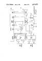
- FIG. 5is a diagram of a master sync (synchronization) generator suitable for use in this invention.
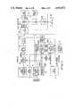
- the user site 100includes a color television camera 101 provided with a set of synchronizing signals generated by count down circuits 102 from a 4 ⁇ Fc carrier.
- the set of count-down circuits 102can all be "reset” when commanded by the central 10 via a signaling demodulator 103 (converts 6 MHz keyed carrier to logic levels). This can be achieved by the central 10 generating a 17-bit number which is adequate to describe a quantity equal to 130 times 525 lines, when the synchronization is found to be incorrect. This number is received at the user site and stored in a register.
Landscapes
- Engineering & Computer Science (AREA)
- Multimedia (AREA)
- Signal Processing (AREA)
- Two-Way Televisions, Distribution Of Moving Picture Or The Like (AREA)
Abstract
Description
Claims (18)
Priority Applications (1)
| Application Number | Priority Date | Filing Date | Title |
|---|---|---|---|
| US06/934,521US4931872A (en) | 1986-11-24 | 1986-11-24 | Methods of and apparatus for the generation of split-screen video displays |
Applications Claiming Priority (1)
| Application Number | Priority Date | Filing Date | Title |
|---|---|---|---|
| US06/934,521US4931872A (en) | 1986-11-24 | 1986-11-24 | Methods of and apparatus for the generation of split-screen video displays |
Publications (1)
| Publication Number | Publication Date |
|---|---|
| US4931872Atrue US4931872A (en) | 1990-06-05 |
Family
ID=25465681
Family Applications (1)
| Application Number | Title | Priority Date | Filing Date |
|---|---|---|---|
| US06/934,521Expired - LifetimeUS4931872A (en) | 1986-11-24 | 1986-11-24 | Methods of and apparatus for the generation of split-screen video displays |
Country Status (1)
| Country | Link |
|---|---|
| US (1) | US4931872A (en) |
Cited By (37)
| Publication number | Priority date | Publication date | Assignee | Title |
|---|---|---|---|---|
| US5040067A (en)* | 1988-07-06 | 1991-08-13 | Pioneer Electronic Corporation | Method and device for processing multiple video signals |
| EP0463790A3 (en)* | 1990-06-29 | 1992-03-04 | Sony Corporation Of America (A Delaware Corporation) | Video synchronisation signal generation |
| US5142367A (en)* | 1989-12-15 | 1992-08-25 | Goldstar Co., Ltd. | System for divisionally displaying plural images on a screen |
| WO1993006690A1 (en)* | 1991-09-17 | 1993-04-01 | Radamec Epo Limited | Setting-up system for remotely controlled cameras |
| US5262861A (en)* | 1990-06-29 | 1993-11-16 | Sony Electronics Inc. | Computer controllable video synchronization and frame pulse signal generator |
| US5473367A (en)* | 1993-06-30 | 1995-12-05 | At&T Corp. | Video view selection by a chairperson |
| USD370010S (en) | 1994-10-21 | 1996-05-21 | Rsi Systems, Inc. | Peripheral video conferencing unit |
| US5572248A (en)* | 1994-09-19 | 1996-11-05 | Teleport Corporation | Teleconferencing method and system for providing face-to-face, non-animated teleconference environment |
| US5615338A (en)* | 1995-05-24 | 1997-03-25 | Titan Information Systems Corporation | System for simultaneously displaying video signal from second video channel and video signal generated at that site or video signal received from first channel |
| US5771065A (en)* | 1992-02-18 | 1998-06-23 | Fujitsu Limited | Picture phone terminal interrupt function and picture phone terminal having communication disconnection notifying function |
| US5781248A (en)* | 1991-11-07 | 1998-07-14 | Canon Kabushiki Kaisha | Multipoint receiving and data processing apparatus |
| US5802281A (en)* | 1994-09-07 | 1998-09-01 | Rsi Systems, Inc. | Peripheral audio/video communication system that interfaces with a host computer and determines format of coded audio/video signals |
| US5835129A (en)* | 1994-09-16 | 1998-11-10 | Southwestern Bell Technology Resources, Inc. | Multipoint digital video composition and bridging system for video conferencing and other applications |
| US5884039A (en)* | 1993-10-01 | 1999-03-16 | Collaboration Properties, Inc. | System for providing a directory of AV devices and capabilities and call processing such that each participant participates to the extent of capabilities available |
| GB2329540A (en)* | 1997-09-17 | 1999-03-24 | Sony Uk Ltd | Surveillance system |
| US5917543A (en)* | 1993-04-15 | 1999-06-29 | Canon Kabushiki Kaisha | Video conference system and control method for the same |
| US5990976A (en)* | 1996-03-14 | 1999-11-23 | Matsushita Electric Industrial Co., Ltd. | Video image processing apparatus and the method of the same |
| US6075571A (en)* | 1997-07-29 | 2000-06-13 | Kuthyar; Ashok K. | Composite image display device and service for video conferencing |
| US20010008427A1 (en)* | 2000-01-19 | 2001-07-19 | Seo Bum Joo | Apparatus and method for supporting picture-in-picture type time shifting |
| US20020124051A1 (en)* | 1993-10-01 | 2002-09-05 | Ludwig Lester F. | Marking and searching capabilities in multimedia documents within multimedia collaboration networks |
| US6449011B1 (en)* | 1992-03-27 | 2002-09-10 | Canon Kabushiki Kaisha | Video camera system having panhead for use in video conference or the like |
| US6469746B1 (en)* | 1992-12-28 | 2002-10-22 | Sanyo Electric Co., Ltd. | Multi-vision screen adapter |
| US6639606B1 (en) | 1997-03-06 | 2003-10-28 | Samsung Electronics Co., Ltd. | Display screen split method for a computer system |
| US20040051780A1 (en)* | 2000-12-01 | 2004-03-18 | Satoru Sudo | Video terminal, video terminal communicating system, and videoconference system |
| US6898620B1 (en) | 1996-06-07 | 2005-05-24 | Collaboration Properties, Inc. | Multiplexing video and control signals onto UTP |
| US20050144284A1 (en)* | 1997-11-04 | 2005-06-30 | Collaboration Properties, Inc. | Scalable networked multimedia system and applications |
| US6937270B1 (en)* | 1999-05-03 | 2005-08-30 | Omnivision Technologies, Inc. | Analog video monitoring system using a plurality of phase locked CMOS image sensors |
| US7185054B1 (en) | 1993-10-01 | 2007-02-27 | Collaboration Properties, Inc. | Participant display and selection in video conference calls |
| US20070093672A1 (en)* | 2005-10-21 | 2007-04-26 | Catalytic Distillation Technologies | Process for producing organic carbonates |
| US20070279483A1 (en)* | 2006-05-31 | 2007-12-06 | Beers Ted W | Blended Space For Aligning Video Streams |
| US20080006487A1 (en)* | 1997-03-12 | 2008-01-10 | Gannett Satellite Information Network, Inc. | Information Display System |
| US20080129816A1 (en)* | 2006-11-30 | 2008-06-05 | Quickwolf Technology, Inc. | Childcare video conferencing system and method |
| US8060905B1 (en)* | 1992-12-09 | 2011-11-15 | Comcast Ip Holdings I, Llc | Television delivery system having interactive electronic program guide |
| US8578410B2 (en) | 2001-08-03 | 2013-11-05 | Comcast Ip Holdings, I, Llc | Video and digital multimedia aggregator content coding and formatting |
| US8621521B2 (en) | 2001-08-03 | 2013-12-31 | Comcast Ip Holdings I, Llc | Video and digital multimedia aggregator |
| US9078014B2 (en) | 2000-06-19 | 2015-07-07 | Comcast Ip Holdings I, Llc | Method and apparatus for targeting of interactive virtual objects |
| US9286294B2 (en) | 1992-12-09 | 2016-03-15 | Comcast Ip Holdings I, Llc | Video and digital multimedia aggregator content suggestion engine |
Citations (6)
| Publication number | Priority date | Publication date | Assignee | Title |
|---|---|---|---|---|
| US3207842A (en)* | 1962-11-16 | 1965-09-21 | Harry D Flagle | Four channel video integrator |
| US3437873A (en)* | 1967-01-20 | 1969-04-08 | Bunker Ramo | Display system sector selection and amplification means |
| US3736377A (en)* | 1971-05-10 | 1973-05-29 | R Warren | Multiple channel video switching system |
| JPS57208781A (en)* | 1981-06-19 | 1982-12-21 | Hitachi Ltd | Conference system by video telephone |
| US4400724A (en)* | 1981-06-08 | 1983-08-23 | The United States Of America As Represented By The Secretary Of The Army | Virtual space teleconference system |
| US4494144A (en)* | 1982-06-28 | 1985-01-15 | At&T Bell Laboratories | Reduced bandwidth video transmission |
- 1986
- 1986-11-24USUS06/934,521patent/US4931872A/ennot_activeExpired - Lifetime
Patent Citations (6)
| Publication number | Priority date | Publication date | Assignee | Title |
|---|---|---|---|---|
| US3207842A (en)* | 1962-11-16 | 1965-09-21 | Harry D Flagle | Four channel video integrator |
| US3437873A (en)* | 1967-01-20 | 1969-04-08 | Bunker Ramo | Display system sector selection and amplification means |
| US3736377A (en)* | 1971-05-10 | 1973-05-29 | R Warren | Multiple channel video switching system |
| US4400724A (en)* | 1981-06-08 | 1983-08-23 | The United States Of America As Represented By The Secretary Of The Army | Virtual space teleconference system |
| JPS57208781A (en)* | 1981-06-19 | 1982-12-21 | Hitachi Ltd | Conference system by video telephone |
| US4494144A (en)* | 1982-06-28 | 1985-01-15 | At&T Bell Laboratories | Reduced bandwidth video transmission |
Non-Patent Citations (2)
| Title |
|---|
| Introducing Luma, Telephony, Jun. 9, 1986, pp. 42 43.* |
| Introducing Luma, Telephony, Jun. 9, 1986, pp. 42-43. |
Cited By (95)
| Publication number | Priority date | Publication date | Assignee | Title |
|---|---|---|---|---|
| US5040067A (en)* | 1988-07-06 | 1991-08-13 | Pioneer Electronic Corporation | Method and device for processing multiple video signals |
| US5142367A (en)* | 1989-12-15 | 1992-08-25 | Goldstar Co., Ltd. | System for divisionally displaying plural images on a screen |
| EP0463790A3 (en)* | 1990-06-29 | 1992-03-04 | Sony Corporation Of America (A Delaware Corporation) | Video synchronisation signal generation |
| US5262861A (en)* | 1990-06-29 | 1993-11-16 | Sony Electronics Inc. | Computer controllable video synchronization and frame pulse signal generator |
| WO1993006690A1 (en)* | 1991-09-17 | 1993-04-01 | Radamec Epo Limited | Setting-up system for remotely controlled cameras |
| US5781248A (en)* | 1991-11-07 | 1998-07-14 | Canon Kabushiki Kaisha | Multipoint receiving and data processing apparatus |
| US5771065A (en)* | 1992-02-18 | 1998-06-23 | Fujitsu Limited | Picture phone terminal interrupt function and picture phone terminal having communication disconnection notifying function |
| US6449011B1 (en)* | 1992-03-27 | 2002-09-10 | Canon Kabushiki Kaisha | Video camera system having panhead for use in video conference or the like |
| US9286294B2 (en) | 1992-12-09 | 2016-03-15 | Comcast Ip Holdings I, Llc | Video and digital multimedia aggregator content suggestion engine |
| US8060905B1 (en)* | 1992-12-09 | 2011-11-15 | Comcast Ip Holdings I, Llc | Television delivery system having interactive electronic program guide |
| US6469746B1 (en)* | 1992-12-28 | 2002-10-22 | Sanyo Electric Co., Ltd. | Multi-vision screen adapter |
| US5917543A (en)* | 1993-04-15 | 1999-06-29 | Canon Kabushiki Kaisha | Video conference system and control method for the same |
| US5473367A (en)* | 1993-06-30 | 1995-12-05 | At&T Corp. | Video view selection by a chairperson |
| US7822813B2 (en) | 1993-10-01 | 2010-10-26 | Ludwig Lester F | Storing and accessing media files |
| US20030187940A1 (en)* | 1993-10-01 | 2003-10-02 | Collaboration Properties, Inc. | Teleconferencing employing multiplexing of video and data conferencing signals |
| US20070083596A1 (en)* | 1993-10-01 | 2007-04-12 | Collaboration Properties, Inc. | Storing and Accessing Media Files |
| US20070083595A1 (en)* | 1993-10-01 | 2007-04-12 | Collaboration Properties, Inc. | Networked Audio Communication with Login Location Information |
| US7730132B2 (en) | 1993-10-01 | 2010-06-01 | Ludwig Lester F | Storing and accessing media files |
| US20070078933A1 (en)* | 1993-10-01 | 2007-04-05 | Collaboration Properties, Inc. | Networked Audio Communication Over Two Networks |
| US7487210B2 (en) | 1993-10-01 | 2009-02-03 | Avistar Communications Corporation | Method for managing real-time communications |
| US7444373B2 (en) | 1993-10-01 | 2008-10-28 | Avistar Communications Corporation | Wireless real-time communication |
| US6212547B1 (en) | 1993-10-01 | 2001-04-03 | Collaboration Properties, Inc. | UTP based video and data conferencing |
| US6237025B1 (en) | 1993-10-01 | 2001-05-22 | Collaboration Properties, Inc. | Multimedia collaboration system |
| US7441001B2 (en) | 1993-10-01 | 2008-10-21 | Avistar Communications Corporation | Real-time wide-area communications between ports |
| US6343314B1 (en) | 1993-10-01 | 2002-01-29 | Collaboration Properties, Inc. | Remote participant hold and disconnect during videoconferencing |
| US6351762B1 (en) | 1993-10-01 | 2002-02-26 | Collaboration Properties, Inc. | Method and system for log-in-based video and multimedia calls |
| US20070078932A1 (en)* | 1993-10-01 | 2007-04-05 | Collaboration Properties, Inc. | Audio Communication with Login Location Addressing |
| US7437411B2 (en) | 1993-10-01 | 2008-10-14 | Avistar Communications Corporation | Communication of a selected type over a wide area network |
| US6426769B1 (en) | 1993-10-01 | 2002-07-30 | Collaboration Properties, Inc. | High-quality switched analog video communications over unshielded twisted pair |
| US6437818B1 (en) | 1993-10-01 | 2002-08-20 | Collaboration Properties, Inc. | Video conferencing on existing UTP infrastructure |
| US20020124051A1 (en)* | 1993-10-01 | 2002-09-05 | Ludwig Lester F. | Marking and searching capabilities in multimedia documents within multimedia collaboration networks |
| US20070078931A1 (en)* | 1993-10-01 | 2007-04-05 | Collaboration Properties, Inc. | System for Managing Real-Time Communications |
| US7437412B2 (en) | 1993-10-01 | 2008-10-14 | Avistar Communications Corporation | Real-time communication of a selected type |
| US7831663B2 (en) | 1993-10-01 | 2010-11-09 | Pragmatus Av Llc | Storage and playback of media files |
| US20070078930A1 (en)* | 1993-10-01 | 2007-04-05 | Collaboration Properties, Inc. | Method for Managing Real-Time Communications |
| US6583806B2 (en) | 1993-10-01 | 2003-06-24 | Collaboration Properties, Inc. | Videoconferencing hardware |
| US6594688B2 (en) | 1993-10-01 | 2003-07-15 | Collaboration Properties, Inc. | Dedicated echo canceler for a workstation |
| US20030158901A1 (en)* | 1993-10-01 | 2003-08-21 | Collaboration Properties, Inc. | UTP based video conferencing |
| US5884039A (en)* | 1993-10-01 | 1999-03-16 | Collaboration Properties, Inc. | System for providing a directory of AV devices and capabilities and call processing such that each participant participates to the extent of capabilities available |
| US7433921B2 (en) | 1993-10-01 | 2008-10-07 | Avistar Communications Corporation | System for real-time communication between plural users |
| US7421470B2 (en) | 1993-10-01 | 2008-09-02 | Avistar Communications Corporation | Method for real-time communication between plural users |
| US7185054B1 (en) | 1993-10-01 | 2007-02-27 | Collaboration Properties, Inc. | Participant display and selection in video conference calls |
| US7412482B2 (en) | 1993-10-01 | 2008-08-12 | Avistar Communications Corporation | System for managing real-time communications |
| US7398296B2 (en) | 1993-10-01 | 2008-07-08 | Avistar Communications Corporation | Networked audio communication over two networks |
| US6789105B2 (en) | 1993-10-01 | 2004-09-07 | Collaboration Properties, Inc. | Multiple-editor authoring of multimedia documents including real-time video and time-insensitive media |
| US20070168426A1 (en)* | 1993-10-01 | 2007-07-19 | Collaboration Properties, Inc. | Storing and Accessing Media Files |
| US7908320B2 (en) | 1993-10-01 | 2011-03-15 | Pragmatus Av Llc | Tracking user locations over multiple networks to enable real time communications |
| US20070088782A1 (en)* | 1993-10-01 | 2007-04-19 | Collaboration Properties, Inc. | Storage and Playback of Media Files |
| US6959322B2 (en) | 1993-10-01 | 2005-10-25 | Collaboration Properties, Inc. | UTP based video conferencing |
| US20060041616A1 (en)* | 1993-10-01 | 2006-02-23 | Collaboration Properties, Inc. | Audio communications using devices with different capabilities |
| US20060041617A1 (en)* | 1993-10-01 | 2006-02-23 | Collaboration Properties, Inc. | Log-in based communications plus two data types |
| US20060059266A1 (en)* | 1993-10-01 | 2006-03-16 | Collaboration Properties, Inc. | Registration based addressing over multiple networks with digital audio communication |
| US20060064461A1 (en)* | 1993-10-01 | 2006-03-23 | Collaboration Properties, Inc. | Using login-based addressing to communicate with listed users |
| US20060075121A1 (en)* | 1993-10-01 | 2006-04-06 | Collaboration Properties, Inc. | Registration based addressing and call handles to establish communication |
| US7054904B2 (en) | 1993-10-01 | 2006-05-30 | Collaboration Properties, Inc. | Marking and searching capabilities in multimedia documents within multimedia collaboration networks |
| US7206809B2 (en) | 1993-10-01 | 2007-04-17 | Collaboration Properties, Inc. | Method for real-time communication between plural users |
| US7152093B2 (en) | 1993-10-01 | 2006-12-19 | Collaboration Properties, Inc. | System for real-time communication between plural users |
| US20070083593A1 (en)* | 1993-10-01 | 2007-04-12 | Collaboration Properties, Inc. | Wireless Networked Audio Communication |
| US6654825B2 (en) | 1994-09-07 | 2003-11-25 | Rsi Systems, Inc. | Peripheral video conferencing system with control unit for adjusting the transmission bandwidth of the communication channel |
| US6519662B2 (en) | 1994-09-07 | 2003-02-11 | Rsi Systems, Inc. | Peripheral video conferencing system |
| US5802281A (en)* | 1994-09-07 | 1998-09-01 | Rsi Systems, Inc. | Peripheral audio/video communication system that interfaces with a host computer and determines format of coded audio/video signals |
| US6397275B1 (en) | 1994-09-07 | 2002-05-28 | Viseon, Inc. | Peripheral video conferencing system |
| US6073192A (en)* | 1994-09-07 | 2000-06-06 | Rsi Systems, Inc. | Peripheral video conferencing system with control unit that controls presentation of remote video signal through the output connector |
| US5835129A (en)* | 1994-09-16 | 1998-11-10 | Southwestern Bell Technology Resources, Inc. | Multipoint digital video composition and bridging system for video conferencing and other applications |
| US20070120954A1 (en)* | 1994-09-19 | 2007-05-31 | Destiny Conferencing Llc | Teleconferencing method and system |
| US6654045B2 (en) | 1994-09-19 | 2003-11-25 | Telesuite Corporation | Teleconferencing method and system |
| US7116350B2 (en) | 1994-09-19 | 2006-10-03 | Destiny Conferencing Llc | Teleconferencing method and system |
| US5572248A (en)* | 1994-09-19 | 1996-11-05 | Teleport Corporation | Teleconferencing method and system for providing face-to-face, non-animated teleconference environment |
| US5751337A (en)* | 1994-09-19 | 1998-05-12 | Telesuite Corporation | Teleconferencing method and system for providing face-to-face, non-animated teleconference environment |
| US6160573A (en)* | 1994-09-19 | 2000-12-12 | Telesuite Corporation | Teleconference method and system for providing face-to-face teleconference environment |
| US20040100553A1 (en)* | 1994-09-19 | 2004-05-27 | Telesuite Corporation | Teleconferencing method and system |
| USD370010S (en) | 1994-10-21 | 1996-05-21 | Rsi Systems, Inc. | Peripheral video conferencing unit |
| US5615338A (en)* | 1995-05-24 | 1997-03-25 | Titan Information Systems Corporation | System for simultaneously displaying video signal from second video channel and video signal generated at that site or video signal received from first channel |
| US5990976A (en)* | 1996-03-14 | 1999-11-23 | Matsushita Electric Industrial Co., Ltd. | Video image processing apparatus and the method of the same |
| US6898620B1 (en) | 1996-06-07 | 2005-05-24 | Collaboration Properties, Inc. | Multiplexing video and control signals onto UTP |
| US6639606B1 (en) | 1997-03-06 | 2003-10-28 | Samsung Electronics Co., Ltd. | Display screen split method for a computer system |
| US20080006487A1 (en)* | 1997-03-12 | 2008-01-10 | Gannett Satellite Information Network, Inc. | Information Display System |
| US6075571A (en)* | 1997-07-29 | 2000-06-13 | Kuthyar; Ashok K. | Composite image display device and service for video conferencing |
| US6462776B2 (en) | 1997-09-17 | 2002-10-08 | Sony United Kingdom Limited | Security control system |
| GB2329540B (en)* | 1997-09-17 | 2002-05-29 | Sony Uk Ltd | Security control system |
| GB2329540A (en)* | 1997-09-17 | 1999-03-24 | Sony Uk Ltd | Surveillance system |
| US20050144284A1 (en)* | 1997-11-04 | 2005-06-30 | Collaboration Properties, Inc. | Scalable networked multimedia system and applications |
| US6937270B1 (en)* | 1999-05-03 | 2005-08-30 | Omnivision Technologies, Inc. | Analog video monitoring system using a plurality of phase locked CMOS image sensors |
| US20010008427A1 (en)* | 2000-01-19 | 2001-07-19 | Seo Bum Joo | Apparatus and method for supporting picture-in-picture type time shifting |
| US9078014B2 (en) | 2000-06-19 | 2015-07-07 | Comcast Ip Holdings I, Llc | Method and apparatus for targeting of interactive virtual objects |
| US9813641B2 (en) | 2000-06-19 | 2017-11-07 | Comcast Ip Holdings I, Llc | Method and apparatus for targeting of interactive virtual objects |
| US7161632B2 (en)* | 2000-12-01 | 2007-01-09 | Ginganet Corporation | Video terminal, video terminal communicating system, and videoconference system |
| US20040051780A1 (en)* | 2000-12-01 | 2004-03-18 | Satoru Sudo | Video terminal, video terminal communicating system, and videoconference system |
| US10349096B2 (en) | 2001-08-03 | 2019-07-09 | Comcast Ip Holdings I, Llc | Video and digital multimedia aggregator content coding and formatting |
| US8621521B2 (en) | 2001-08-03 | 2013-12-31 | Comcast Ip Holdings I, Llc | Video and digital multimedia aggregator |
| US8578410B2 (en) | 2001-08-03 | 2013-11-05 | Comcast Ip Holdings, I, Llc | Video and digital multimedia aggregator content coding and formatting |
| US10140433B2 (en) | 2001-08-03 | 2018-11-27 | Comcast Ip Holdings I, Llc | Video and digital multimedia aggregator |
| US20070093672A1 (en)* | 2005-10-21 | 2007-04-26 | Catalytic Distillation Technologies | Process for producing organic carbonates |
| US20070279483A1 (en)* | 2006-05-31 | 2007-12-06 | Beers Ted W | Blended Space For Aligning Video Streams |
| US20080129816A1 (en)* | 2006-11-30 | 2008-06-05 | Quickwolf Technology, Inc. | Childcare video conferencing system and method |
Similar Documents
| Publication | Publication Date | Title |
|---|---|---|
| US4931872A (en) | Methods of and apparatus for the generation of split-screen video displays | |
| US4393394A (en) | Television image positioning and combining system | |
| CA2101437C (en) | Television system for displaying multiple views of a remote location | |
| US5194952A (en) | Video processing system having improved transition control and display | |
| US5162904A (en) | Video processing system having improved internal switching capability | |
| US6215781B1 (en) | Video transmitting apparatus | |
| US5627825A (en) | Video communication apparatus | |
| US5818416A (en) | Image size adjusting apparatus for a digital display monitor | |
| JPH02237280A (en) | Standard/high definition television receiver | |
| EP0711071B1 (en) | Vertical panning system for interlaced video | |
| US2875270A (en) | Subscription-television system | |
| GB2173667A (en) | Stereoscopic television system and apparatus | |
| US20060082663A1 (en) | Video camera | |
| US6356316B1 (en) | Microkeyer: microcomputer broadcast video overlay device and method | |
| US4413273A (en) | System for mixing two color television signals | |
| US3420951A (en) | Television transmission delay compensation apparatus | |
| US3984633A (en) | Apparatus for altering the position of a video image without rescanning of the originally generated image | |
| KR930009866B1 (en) | TV receiver | |
| US5170246A (en) | Video processing system having improved synchronization | |
| JP3421864B2 (en) | Video camera | |
| KR0182066B1 (en) | Image signal transformation apparatus of digital formation | |
| KR100435176B1 (en) | Color Demodulation For Digital Television | |
| JP2794581B2 (en) | Video signal processing device | |
| KR100296745B1 (en) | Circuit of indicating television display area | |
| JPH0157867B2 (en) |
Legal Events
| Date | Code | Title | Description |
|---|---|---|---|
| AS | Assignment | Owner name:GTE LABORATORIES INCORPORATED, A CORP OF DE Free format text:ASSIGNMENT OF ASSIGNORS INTEREST.;ASSIGNORS:STODDARD, JAMES C.;TWEEDY, ERNEST P.;REEL/FRAME:004635/0968 Effective date:19861117 | |
| STCF | Information on status: patent grant | Free format text:PATENTED CASE | |
| FEPP | Fee payment procedure | Free format text:PAYOR NUMBER ASSIGNED (ORIGINAL EVENT CODE: ASPN); ENTITY STATUS OF PATENT OWNER: LARGE ENTITY | |
| FEPP | Fee payment procedure | Free format text:PAYER NUMBER DE-ASSIGNED (ORIGINAL EVENT CODE: RMPN); ENTITY STATUS OF PATENT OWNER: LARGE ENTITY Free format text:PAYOR NUMBER ASSIGNED (ORIGINAL EVENT CODE: ASPN); ENTITY STATUS OF PATENT OWNER: LARGE ENTITY | |
| FPAY | Fee payment | Year of fee payment:4 | |
| FPAY | Fee payment | Year of fee payment:8 | |
| SULP | Surcharge for late payment | ||
| FEPP | Fee payment procedure | Free format text:PAYOR NUMBER ASSIGNED (ORIGINAL EVENT CODE: ASPN); ENTITY STATUS OF PATENT OWNER: LARGE ENTITY Free format text:PAYER NUMBER DE-ASSIGNED (ORIGINAL EVENT CODE: RMPN); ENTITY STATUS OF PATENT OWNER: LARGE ENTITY | |
| FPAY | Fee payment | Year of fee payment:12 | |
| AS | Assignment | Owner name:VERIZON LABORATORIES INC., MASSACHUSETTS Free format text:CHANGE OF NAME;ASSIGNOR:GTE LABORATORIES INCORPORATED;REEL/FRAME:019193/0372 Effective date:20000630 |