US4931050A - Constant pressure variable flow pump - Google Patents
Constant pressure variable flow pumpDownload PDFInfo
- Publication number
- US4931050A US4931050AUS07/180,916US18091688AUS4931050AUS 4931050 AUS4931050 AUS 4931050AUS 18091688 AUS18091688 AUS 18091688AUS 4931050 AUS4931050 AUS 4931050A
- Authority
- US
- United States
- Prior art keywords
- flow restriction
- restriction element
- fluid
- flow
- infusion
- Prior art date
- Legal status (The legal status is an assumption and is not a legal conclusion. Google has not performed a legal analysis and makes no representation as to the accuracy of the status listed.)
- Expired - Lifetime
Links
- 238000001802infusionMethods0.000claimsabstractdescription33
- 238000003780insertionMethods0.000claimsabstractdescription18
- 230000037431insertionEffects0.000claimsabstractdescription18
- 230000008878couplingEffects0.000claimsabstractdescription12
- 238000010168coupling processMethods0.000claimsabstractdescription12
- 238000005859coupling reactionMethods0.000claimsabstractdescription12
- 238000002513implantationMethods0.000claimsabstractdescription7
- 239000012530fluidSubstances0.000claimsdescription35
- 238000007789sealingMethods0.000claimsdescription8
- 238000004891communicationMethods0.000claimsdescription3
- 230000004323axial lengthEffects0.000claims2
- 230000035515penetrationEffects0.000claims1
- 239000003814drugSubstances0.000abstractdescription16
- 229940079593drugDrugs0.000abstractdescription16
- 238000012377drug deliveryMethods0.000abstractdescription4
- 238000000034methodMethods0.000description13
- 238000002347injectionMethods0.000description8
- 239000007924injectionSubstances0.000description8
- NOESYZHRGYRDHS-UHFFFAOYSA-NinsulinChemical compoundN1C(=O)C(NC(=O)C(CCC(N)=O)NC(=O)C(CCC(O)=O)NC(=O)C(C(C)C)NC(=O)C(NC(=O)CN)C(C)CC)CSSCC(C(NC(CO)C(=O)NC(CC(C)C)C(=O)NC(CC=2C=CC(O)=CC=2)C(=O)NC(CCC(N)=O)C(=O)NC(CC(C)C)C(=O)NC(CCC(O)=O)C(=O)NC(CC(N)=O)C(=O)NC(CC=2C=CC(O)=CC=2)C(=O)NC(CSSCC(NC(=O)C(C(C)C)NC(=O)C(CC(C)C)NC(=O)C(CC=2C=CC(O)=CC=2)NC(=O)C(CC(C)C)NC(=O)C(C)NC(=O)C(CCC(O)=O)NC(=O)C(C(C)C)NC(=O)C(CC(C)C)NC(=O)C(CC=2NC=NC=2)NC(=O)C(CO)NC(=O)CNC2=O)C(=O)NCC(=O)NC(CCC(O)=O)C(=O)NC(CCCNC(N)=N)C(=O)NCC(=O)NC(CC=3C=CC=CC=3)C(=O)NC(CC=3C=CC=CC=3)C(=O)NC(CC=3C=CC(O)=CC=3)C(=O)NC(C(C)O)C(=O)N3C(CCC3)C(=O)NC(CCCCN)C(=O)NC(C)C(O)=O)C(=O)NC(CC(N)=O)C(O)=O)=O)NC(=O)C(C(C)CC)NC(=O)C(CO)NC(=O)C(C(C)O)NC(=O)C1CSSCC2NC(=O)C(CC(C)C)NC(=O)C(NC(=O)C(CCC(N)=O)NC(=O)C(CC(N)=O)NC(=O)C(NC(=O)C(N)CC=1C=CC=CC=1)C(C)C)CC1=CN=CN1NOESYZHRGYRDHS-UHFFFAOYSA-N0.000description8
- 239000008280bloodSubstances0.000description7
- 210000004369bloodAnatomy0.000description7
- 238000005516engineering processMethods0.000description7
- 238000012856packingMethods0.000description6
- 102000004877InsulinHuman genes0.000description4
- 108090001061InsulinProteins0.000description4
- 239000007943implantSubstances0.000description4
- 238000001727in vivoMethods0.000description4
- 229940125396insulinDrugs0.000description4
- 238000012423maintenanceMethods0.000description4
- 239000000243solutionSubstances0.000description4
- 238000011010flushing procedureMethods0.000description3
- 239000007788liquidSubstances0.000description3
- 238000004519manufacturing processMethods0.000description3
- 238000003860storageMethods0.000description3
- 230000001580bacterial effectEffects0.000description2
- 238000013461designMethods0.000description2
- 238000000605extractionMethods0.000description2
- 230000037406food intakeEffects0.000description2
- 238000009966trimmingMethods0.000description2
- 206010053567CoagulopathiesDiseases0.000description1
- 239000010836blood and blood productSubstances0.000description1
- 229940125691blood productDrugs0.000description1
- 229940044683chemotherapy drugDrugs0.000description1
- 230000035602clottingEffects0.000description1
- 230000006835compressionEffects0.000description1
- 238000007906compressionMethods0.000description1
- 238000011109contaminationMethods0.000description1
- 206010012601diabetes mellitusDiseases0.000description1
- 239000003085diluting agentSubstances0.000description1
- 231100000673dose–response relationshipToxicity0.000description1
- 238000002651drug therapyMethods0.000description1
- 230000000694effectsEffects0.000description1
- 235000013305foodNutrition0.000description1
- 238000011065in-situ storageMethods0.000description1
- 239000000463materialSubstances0.000description1
- 235000012054mealsNutrition0.000description1
- 238000012986modificationMethods0.000description1
- 230000004048modificationEffects0.000description1
- 230000000737periodic effectEffects0.000description1
- 230000002035prolonged effectEffects0.000description1
- 238000005070samplingMethods0.000description1
- 238000004904shorteningMethods0.000description1
- 238000004513sizingMethods0.000description1
- 238000010254subcutaneous injectionMethods0.000description1
- 239000007929subcutaneous injectionSubstances0.000description1
- 238000002560therapeutic procedureMethods0.000description1
- 230000002792vascularEffects0.000description1
Images


Classifications
- A—HUMAN NECESSITIES
- A61—MEDICAL OR VETERINARY SCIENCE; HYGIENE
- A61M—DEVICES FOR INTRODUCING MEDIA INTO, OR ONTO, THE BODY; DEVICES FOR TRANSDUCING BODY MEDIA OR FOR TAKING MEDIA FROM THE BODY; DEVICES FOR PRODUCING OR ENDING SLEEP OR STUPOR
- A61M5/00—Devices for bringing media into the body in a subcutaneous, intra-vascular or intramuscular way; Accessories therefor, e.g. filling or cleaning devices, arm-rests
- A61M5/14—Infusion devices, e.g. infusing by gravity; Blood infusion; Accessories therefor
- A61M5/142—Pressure infusion, e.g. using pumps
- A61M5/14244—Pressure infusion, e.g. using pumps adapted to be carried by the patient, e.g. portable on the body
- A61M5/14276—Pressure infusion, e.g. using pumps adapted to be carried by the patient, e.g. portable on the body specially adapted for implantation
- A—HUMAN NECESSITIES
- A61—MEDICAL OR VETERINARY SCIENCE; HYGIENE
- A61M—DEVICES FOR INTRODUCING MEDIA INTO, OR ONTO, THE BODY; DEVICES FOR TRANSDUCING BODY MEDIA OR FOR TAKING MEDIA FROM THE BODY; DEVICES FOR PRODUCING OR ENDING SLEEP OR STUPOR
- A61M5/00—Devices for bringing media into the body in a subcutaneous, intra-vascular or intramuscular way; Accessories therefor, e.g. filling or cleaning devices, arm-rests
- A61M5/14—Infusion devices, e.g. infusing by gravity; Blood infusion; Accessories therefor
- A61M5/141—Infusion devices, e.g. infusing by gravity; Blood infusion; Accessories therefor with capillaries for restricting fluid flow
- A—HUMAN NECESSITIES
- A61—MEDICAL OR VETERINARY SCIENCE; HYGIENE
- A61M—DEVICES FOR INTRODUCING MEDIA INTO, OR ONTO, THE BODY; DEVICES FOR TRANSDUCING BODY MEDIA OR FOR TAKING MEDIA FROM THE BODY; DEVICES FOR PRODUCING OR ENDING SLEEP OR STUPOR
- A61M5/00—Devices for bringing media into the body in a subcutaneous, intra-vascular or intramuscular way; Accessories therefor, e.g. filling or cleaning devices, arm-rests
- A61M5/14—Infusion devices, e.g. infusing by gravity; Blood infusion; Accessories therefor
- A61M5/168—Means for controlling media flow to the body or for metering media to the body, e.g. drip meters, counters ; Monitoring media flow to the body
- A61M5/16877—Adjusting flow; Devices for setting a flow rate
- A61M5/16881—Regulating valves
- F—MECHANICAL ENGINEERING; LIGHTING; HEATING; WEAPONS; BLASTING
- F16—ENGINEERING ELEMENTS AND UNITS; GENERAL MEASURES FOR PRODUCING AND MAINTAINING EFFECTIVE FUNCTIONING OF MACHINES OR INSTALLATIONS; THERMAL INSULATION IN GENERAL
- F16L—PIPES; JOINTS OR FITTINGS FOR PIPES; SUPPORTS FOR PIPES, CABLES OR PROTECTIVE TUBING; MEANS FOR THERMAL INSULATION IN GENERAL
- F16L55/00—Devices or appurtenances for use in, or in connection with, pipes or pipe systems
- F16L55/02—Energy absorbers; Noise absorbers
- F16L55/027—Throttle passages
- G—PHYSICS
- G05—CONTROLLING; REGULATING
- G05D—SYSTEMS FOR CONTROLLING OR REGULATING NON-ELECTRIC VARIABLES
- G05D7/00—Control of flow
- G05D7/01—Control of flow without auxiliary power
- G05D7/0186—Control of flow without auxiliary power without moving parts
- A—HUMAN NECESSITIES
- A61—MEDICAL OR VETERINARY SCIENCE; HYGIENE
- A61M—DEVICES FOR INTRODUCING MEDIA INTO, OR ONTO, THE BODY; DEVICES FOR TRANSDUCING BODY MEDIA OR FOR TAKING MEDIA FROM THE BODY; DEVICES FOR PRODUCING OR ENDING SLEEP OR STUPOR
- A61M2205/00—General characteristics of the apparatus
- A61M2205/35—Communication
- A61M2205/3507—Communication with implanted devices, e.g. external control
- A—HUMAN NECESSITIES
- A61—MEDICAL OR VETERINARY SCIENCE; HYGIENE
- A61M—DEVICES FOR INTRODUCING MEDIA INTO, OR ONTO, THE BODY; DEVICES FOR TRANSDUCING BODY MEDIA OR FOR TAKING MEDIA FROM THE BODY; DEVICES FOR PRODUCING OR ENDING SLEEP OR STUPOR
- A61M5/00—Devices for bringing media into the body in a subcutaneous, intra-vascular or intramuscular way; Accessories therefor, e.g. filling or cleaning devices, arm-rests
- A61M5/14—Infusion devices, e.g. infusing by gravity; Blood infusion; Accessories therefor
- A61M5/168—Means for controlling media flow to the body or for metering media to the body, e.g. drip meters, counters ; Monitoring media flow to the body
- A61M5/16804—Flow controllers
- A61M5/16813—Flow controllers by controlling the degree of opening of the flow line
- Y—GENERAL TAGGING OF NEW TECHNOLOGICAL DEVELOPMENTS; GENERAL TAGGING OF CROSS-SECTIONAL TECHNOLOGIES SPANNING OVER SEVERAL SECTIONS OF THE IPC; TECHNICAL SUBJECTS COVERED BY FORMER USPC CROSS-REFERENCE ART COLLECTIONS [XRACs] AND DIGESTS
- Y10—TECHNICAL SUBJECTS COVERED BY FORMER USPC
- Y10S—TECHNICAL SUBJECTS COVERED BY FORMER USPC CROSS-REFERENCE ART COLLECTIONS [XRACs] AND DIGESTS
- Y10S128/00—Surgery
- Y10S128/12—Pressure infusion
Definitions
- This inventionrelates to an implantable infusion pump.
- itrelates to an infusion system utilizing a rechargeable, implantable constant pressure pump together with unique catheter arrangements to provide variable infusion rates.
- Infusion pumpsthat are implanted in the body for delivery of an infusate, typically a medication or insulin to a selected site in the living body have reached the point of commercial and medical acceptance.
- Those devicesgenerally fall into two categories. The first, are so-called constant flow devices which are used in a variety of medical applications, for example, to dispense chemotherapy drugs at a relatively constant flow rate.
- the technology represented by such constant flow devicesis found in U.S. Pat. Nos. 3,731,681; 4,193,397; and 4,258,711.
- Those patentsare representative of a number of other patented technology wherein an infusion apparatus relies on a liquid/vapor equilibrium to maintain constant pressure on the drug which flows through a capillary in order to maintain a constant flow rate.
- the deviceis implanted in the body to remain there for a prolonged period and is refilled with an infusate without the need for removal. Refilling is achieved by injecting additional infusate through a penetrable septum in the apparatus. The septum is located directly under the patient's skin and is sensed by tactile location. During the act of refilling of the apparatus with infusate, recharging of the apparatus' power supply also takes place since the liquid/vapor equilibrium is shifted by an increase in pressure in the infusate chamber.
- a second class of devicesare the so-called "programmable" devices which employ a valve or other device controlled by a programmer so that the dosage rate can be varied to suit the needs of a particular patient.
- An exampleis diabetes, where the quantity of medication, such as insulin, to be infused varies as a function of the requirements of the patient. Such fluctuations can occur on a daily basis or, randomly as a function of the ingestion of food.
- the patientreceives a small continuous or basal dose to satisfy a particular steady state requirement as a function of the average amount of sugar in his blood following eating, when blood sugar levels rise dramatically, the infusion apparatus is programmed to dispense a larger (bolus) dose of insulin to offset the increased sugar level caused by the ingestion of a meal.
- the technology represented by such programmable devicesis represented in U.S. Pat. Nos. 4,077,405; 4,443,218; 4,447,224; and 4,714,462.
- U.S. Pat. No. 4,496,343relies on a constant pressure implantable infusion pump having attached to it an auxiliary chamber used for unrestricted bolus injections of medication and other fluids through the pump's infusion line, generally a catheter, to the delivery site.
- This auxiliary chamber or "bolus port”contains its own self-sealing septum which is accessed percutaneously via a hollow needle puncture.
- the auxiliary chamberis serially connected to the reservoir and, whether mounted internal or external to the pump, fluid flowing through the main reservoir passes through this auxiliary chamber prior to exiting through the delivery catheter.
- auxiliary porthas been demonstrated by commercial devices such as the Infusaid Model 400 to perform bolus injections, and to provide the ability to maintain catheter patency by periodic or high-pressure flushing. Additionally, such auxiliary ports provide additional flexibility with respect to the extraction of fluid samples such as blood from the delivery site. Such flexibility is inherent in a system which utilizes a single bolus port but cannot be accomplished in a system that employs valve technology such as the '711 patent.
- a bolus injectionwill force the infusate stored in the chamber through the catheter as the chamber volume is flushed. While such a characteristic is present in systems designed by the '343 patent, as noted, for certain drug therapy such as insulin, the therapy regime cannot tolerate a bolus drug injection per se and thus, a different flow configuration must be pursued which allows the use of an auxiliary port without the hazards of chamber flushing. Additionally, while the extraction of blood from the delivery site is desirable from a diagnostic standpoint, such may cause a build-up of blood products on the internal, relatively small, passages of the capillary tubing in '343. This in turn may lead to clotting and the blockage of flow. Obviously, alternative configurations are required.
- Capillary tube restrictorswhich are used in such implantable devices have the advantage of providing a simple and low cost fluid restriction.
- large internal diameters0.003-0.004 inches
- long lengthssometimes in excess of thirty feet wrapped around the implantable device
- the overall length and the internal diameterare chosen to provide low shear rate, laminar flow in order to reduce the stress on a specific drug solution which may be sensitive to shear.
- long lengths of capillary tubingincrease the space requirement and overall weight of the system. In the context of an implantable device, these two properties are significant drawbacks in that they limit areas where implantation may occur and provide a degree of user discomfort.
- the actual measuring, calibration and trimming of long tube lengthsis labor intensive and requires a considerable amount of time.
- U.S. Pat. No. 3,951,147 relating to an implantable infusate devicedescribes a technique for replacing the long length of catheter tubing by employing a flow controller utilizing a large bore diameter tubing having placed therein a resistance wire. By properly sizing the diameter and length of the resistance wire, flow control can be maintained.
- the '147 patenttherefore proceeds by reducing the overall length of the capillary tubing through the use of a shorter tubing having placed therein a predetermined length of wire to achieve the necessary flow characteristics of the overall device.
- Yet another object of this inventionis to provide for a flow restriction system that provides relatively low shear rates in the context of a constant pressure variable flow device.
- Still another object of this inventionis to provide a variable flow device which allows for flow rate readjustment following implant, an advantage not possible in capillary tube restrictor technology.
- a further object of this inventionis to define a flow connection system that employs an auxiliary bolus port and its associated flow connections that does not require that infusate from the main reservoir pass through the bolus injection chamber to allow for flexibility in either direct bolus injection or the use of the auxiliary port for in-situ sampling.
- a constant pressure delivery systemgiven a refill septum and a main reservoir chamber. Infusate from the main reservoir chamber is delivered to the system utilizing a liquid/vapor equilibrium in the device to maintain constant pressure on the drug which then flows through an outlet capillary at an initial constant rate.
- a needle restrictoris placed in the capillary tube having a variable insertion distance. By utilizing various techniques external to the capillary, the needle restrictor may have its effective length in the capillary changed to thereby vary the effective restriction within the capillary and thus determine flow rate.
- the needle restrictor's lengthis varied, for example, by shortening the effective length to decrease the resistance and increase the dosage or conversely, to increase the effective length and decrease the dosage.
- Varying techniquesare employed to move the restrictor needle.
- fluid cylinder actuated by means of external pressure, lead screw adjustment techniques, linear stylet techniques and the likemay by employed.
- a T-connectorcan be used to couple the fluid output from the main reservoir chamber such that the auxiliary or bolus port delivers infusate directly into the outlet catheter. By this technique, medication from the main reservoir chamber does not pass through the auxiliary chamber.
- a double lumen cathetermay be used having one lumen receiving the output from the main reservoir chamber and the second receiving output from the bolus port. Such provides for parallel output.
- a combination of parallel output utilizing a double lumen catheter and serial output utilizing a second bolus port in a T-connection in the infusion pathmay be employed.
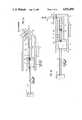
- FIG. 1Ais a schematic perspective drawing illustrating a capillary tube used in accordance with this invention.
- FIG. 1Bis a schematic side view illustrating a capillary tube having an adjustable needle restrictor
- FIG. 1Cis an end view of the capillary and restrictor of FIG. 1B;
- FIGS. 2A and 2Billustrate a first embodiment of this invention utilizing a linearly trimmed and fixed needle restrictor in an infusate system
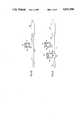
- FIGS. 3A, 3B and 3Cillustrate a second embodiment of an adjustable implanted variable flow system used in conjunction with a constant pressure drug delivery device
- FIGS. 4A, 4B and 4Cillustrate a third embodiment of this invention utilizing a serial, parallel and hybrid serial/parallel bolus port system.
- the capillary flow restrictor in accordance with this inventioncomprises an outer capillary tube 10 having a given length (1) and an inside diameter (d).
- a needle slide 12is placed into the capillary tube 10.
- the needle slide 12has a diameter (D) and is inserted for a variable insertion length (L).
- a radial clearance gap (A)exists which is equal to 1/2 of the diametrical clearance such that the needle slide diameter (D) is very much greater than the gap (A).
- variable flow capillary tube restrictoris a 2-part device comprised of a housing, that is the capillary tube and a needle slide.
- the capillary tubeis essentially a smooth bore, semi-rigid tube into which the needle slide is positioned.
- the outer diameter of a needle slide (D)is also smooth and of a dimension which significantly matches the inside diameter (d) of the tube.
- Adiametrical clearance
- the relative length of insertion (L) of the needle slide in the housingdetermines the resistance, that is the actual restriction.
- the valveis linearly proportional to the length of insertion.
- d, 1, D, A and Lare as defined above.
- the inside diameter of the housingis large enough so that its hydraulic resistance is much less than that of the slide-to-housing clearance gap and is therefore negligibly restrictive with respect to this gap.
- the function of the restriction in the deviceis therefore the length of the flow gap (L) caused by the relative insertion position of the needle slide 12 in the capillary 10.
- the capillary tube restrictor per sewhich is a single element device with a fixed inside diameter and a trimmable length. Its flow restriction is fixed and determined solely by the inside diameter of the tube length. Consequently, as set forth in Equation 1 the restriction is set by having a fluid flow through the tube, measuring the flow rate, recutting the length of the tube in the amount proportional to the flow rate change and then reflowing to verify the new rate. Once cut, the flow rate cannot be readjusted back to the old values. Similarly, when the needle has been trimmed and fixed in the case of the prior art '147 patent, no capability exists for further adjustability.
- This inventiontherefore departs from those prior art schemes by allowing the needle restrictor flow geometries to be altered by changing the insertion distance of the needle.
- the elementsmaintain their relative positions during use.
- the relative positions of the needle and the housingcan be maintained by utilizing arcuate shapes such that the needle slide is frictionally locked into the housing by the spring tension of the slide to the housing inside diameter.
- FIG. 2Aillustrates in schematic form the system which is insertable into a body cavity.
- the casing which forms the overall housingis illustrated by dashed lines to show those elements so packaged.
- a storage chamber 20comprises a positive pressure drug reservoir in accordance with this invention.
- This devicewill be similar to the drug reservoir in a commercially available unit such as an Infusaid Model 100 or, Model 400, both manufactured by Shiley Infusaid, Inc. The device will be discussed herein only for an appreciation of the invention, it being understood that a commercially available component may be used.
- the storage chamber 20comprises a housing which contains infusate in a reservoir 22.
- the path of fluid communication established between the chamber 22 and a delivery catheter 24is illustrated by the arrows in FIG. 2A. This is the "forward flow" direction from the storage chamber to the infusion site.
- infusate within housing 22when infusate within housing 22 is exhausted, it may be refilled by subcutaneous injection through a self-sealing septum 26.
- the septum 26when the device is properly implanted, the septum 26 is located directly beneath the patient's skin and accessible via syringe.
- the device 20contains a bellows 28 which divides the device into two chambers, a first chamber 22 containing infusate and a second chamber 30, which is used to drive the bellows in accordance with the fluid/vapor equilibrium maintained utilizing Freon or the like.
- the outlet pathincludes a bacterial filter 32 and a rigid reservoir attachment 34.
- the attachment 34serves as a coupling between the pump interior and the housing 10 into which the needle slide 12 is inserted.
- an outlet bulkhead attachment 36is placed so that a rigid fixed length of housing 10 exists between the rigid reservoir attachment 34 and the outlet bulkhead attachment 36.
- the outlet bulkhead attachment 36has a coupling chamber 38 to which the delivery catheter 24 is attached. It will be appreciated that the illustration in FIG. 2A is highly schematic to merely show the position of the elements. The actual device would be packaged much like current Infusaid models to have suture tie downs, minimum bulk and septum access.
- the needle restrictor housing 10is relatively rigid while the delivery catheter 24 may be highly flexible to allow positioning within a body cavity to the infusate site.
- the needle slide 12is inserted through the outlet bulkhead attachment 36 into the housing 10 until the desired flow rate is achieved.
- a flow ratecan be positively monitored and dynamically adjusted.
- the needle slide 12may be trimmed and sealed to the outlet bulkhead attachment.
- FIG. 2Bcarrying the same designation of common elements of FIG. 2A, illustrates a variation of this embodiment.
- the restrictor 10is attached to the pump housing via a seal packing 40.
- the packingmay be a series of annular O-rings placed in compression within the outlet bulkhead attachment 36. This packing provides a sealed interface between the fluid flow path and the pump exterior. The seal allows repositioning of the insertion needle 12 for a simplified setting of flow restriction during manufacture or possible reset during use.
- the seal packing 40is located at the downstream end of the flow restrictor. That is, it is placed in a position downstream of the fluid flow from the housing 10 through the bulkhead 36 into the catheter 24. Such was important from a product safety standpoint because the failure of the sealed packing would not permit unrestricted "dumping" of the reservoir. Additionally, placing the seal distal to the restrictor means that fluid volume displaced during repositioning would be displaced into the reservoir and not to the infusion site, that is movement of the needle slide will not vary the infusate dose.
- the needle slidemay be repositioned after initial setting therefore providing variable flow rate setting of the pump during actual use. That is, in-vivo adjustment may be obtained after implantation.
- FIGS. 3A, 3B and 3Cillustrates three configurations to permit such repositioning of the flow restriction and therefore flow rate during in-vivo use of the system.
- the exterior of the pump housingis illustrated, in part, as element 70.
- the reservoir attachment 34, the fixed needle restrictor housing 10, and the outlet bulkhead attachment 36are all contained within the pump housing.
- the delivery catheter 24would, however, be external to that housing.
- FIG. 3Aillustrates a technique of percutaneously readjusting the restrictor 12 by employing a wire stylet through a large bore needle 44.
- the stylet 42 and large bore needle 44can be placed in a self-sealing septum used for flow rate reset or a bolus septum similar to that disclosed in U.S. Pat. No. 4,496,343.
- a penetrable septum 46placed below the skin surface illustrated schematically as skin layer 50.
- the housing 48 holding the septum 46 in placehas a vent 52 to provide for pressure relief as a function of sliding movement of the stylet 42.
- the stylet 42is coupled to the needle slide 12 via a sliding threaded coupling 54.
- One technique of accurately setting the restrictor positionwould be to push the needle 12 to its maximum restriction position, that is maximum insertion by stylet movement and then to "back" the needle out to a specific, precalibrated length to achieve the calibrated flow rate.
- the needle slidewould be held in position by frictional contact with both the packing sealing 40 and the threaded coupling 54.
- FIG. 3Billustrates a configuration employing a fluid cylinder/actuator used to provide restrictor repositioning.
- the self-sealing septum 46is punctured via a syringe 55 and a fluid contained in the syringe is injected to push the restrictor to its maximum closed position as illustrated by the arrows in FIG. 3B.
- the fluidis illustrated schematically as element 56 within the chamber 48 with a sealed piston actuator 58 used to maintain an air-tight interface between the entrained air in zone 60 on one side of the piston and the fluid 56 on the other side of the piston 58.
- fluid pressure in pushing against a spring loaded cylindercould be used to set the restrictor position.
- FIG. 3Cillustrates yet another variation employing a mechanical configuration to allow readjustment of the flow restriction following implant.
- a rotating seal 72Positioned on the housing is a rotating seal 72 which is maintained in a fluid-tight relationship by means of O-ring 74 and the like.
- the needle slide 12has one end coupled to the lead nut coupling 76. That lead nut coupling is mounted on a lead screw 78.
- a stylet 84Through a large bore needle 80 is inserted a stylet 84 which has on one end, external to the skin, a shaped tip, for example, a hexagonal head, Phillips head, or the like and on the other end, a rotating knob 82.
- the shaped tip terminal end of the stylet 84seats in the rotating seal 72.
- one end of the lead screw 78is also fixed to the rotating seal 72.
- the knob 82is rotated, a corresponding rotation is imparted via the stylet 84, rotating seal 72, and lead screw 78.
- the lead nut coupling being threaded on the lead screwtherefore causes movement of the needle slide depending on the direction of rotation of the knob 82.
- each devicecan be configured to allow for readjustment of the flow restriction and thus flow rate after implant utilizing procedures which do not disturb the in-vivo nature of the device. Such is not possible with a capillary tube restrictor which offers only a single opportunity for calibration prior to implant.
- FIGS. 4A, 4B, and 4Ca second aspect of this invention is depicted.
- Those elements common to the descriptions in FIGS. 2 and 3contain the same numerals.
- the constant pressure reservoir, refill septum, bacterial filter and the likeare all provided with common numerals.
- a flow restrictor of the type illustrated in FIGS. 2 and 3is schematically illustrated as the restriction 90.
- FIGS. 4A, 4B, and 4Cillustrate three different configurations for attachment of an auxiliary chamber or "bolus port" 92 to an infusion pump flow system.
- a bolus portcomprises a self-sealing septum 94, a chamber 96, and an outlet 98.
- Such an auxiliary bolus chamberis described per se in U.S. Pat. No. 4,496,343.
- FIG. 4Aillustrates a configuration providing the bolus port 92 plumbed in a spur line fashion utilizing a T-connector 100.
- the auxiliary chamber 96is filled with a non-reactive solution such as a drug diluent. Normal flow occurs past the chamber via the output line 102 from the main reservoir chamber 22 to the outlet catheter 24. Thus, a drug is not stored in the chamber 96.
- the only drug solution which is washed into the bodyis that which is contained in the catheter line downstream of the port 92. That is, the only residual drug solution which is forced through the catheter is that which exists from the T-connector 100 through the outlet of the catheter 24.
- This volumeis relatively small with respect to the chamber volume and thus the effects are much less severe than in past techniques.
- the flow path illustrated in FIG. 4Awould still allow for catheter maintenance through the port 92 and such techniques, for example, withdrawal of blood, could therefore be employed for diagnostic purposes at the infusion site.
- FIG. 4Billustrates a second flow configuration specifically designed for blood withdrawal.
- the flow portis completely separate from the drug infusion line.
- This configurationemploys a parallel set of infusion lines, the drug delivery line along conduit 102 and a separate line 104 providing two outlets to the double lumen catheter 106.
- the port 92thus provides the capability of bolus injection as well as fluid withdrawal at the delivery site. This can be accomplished without in any way interrupting the flow of fluids from the main reservoir chamber 22 through the other lumen of the double lumen catheter 106.
- One advantage of this embodimentis the ability to design a port free of small internal flow passages much in the way vascular access ports are now configured.
- FIG. 4Can additional port 92 (having the same numerals as that of port 92 but "primed") is added to the system of FIG. 4B. This additional port may be used specifically for catheter maintenance along line 102 and still be maintained separate from the blood/fluid withdrawal line 104 by the use of the double lumen catheter.
Landscapes
- Health & Medical Sciences (AREA)
- Engineering & Computer Science (AREA)
- Public Health (AREA)
- Animal Behavior & Ethology (AREA)
- Life Sciences & Earth Sciences (AREA)
- Anesthesiology (AREA)
- Biomedical Technology (AREA)
- Heart & Thoracic Surgery (AREA)
- Hematology (AREA)
- Physics & Mathematics (AREA)
- Veterinary Medicine (AREA)
- General Health & Medical Sciences (AREA)
- Vascular Medicine (AREA)
- General Engineering & Computer Science (AREA)
- Fluid Mechanics (AREA)
- Mechanical Engineering (AREA)
- General Physics & Mathematics (AREA)
- Automation & Control Theory (AREA)
- Infusion, Injection, And Reservoir Apparatuses (AREA)
- Reciprocating Pumps (AREA)
- Media Introduction/Drainage Providing Device (AREA)
- Prostheses (AREA)
- Lubrication Of Internal Combustion Engines (AREA)
- Fluid-Pressure Circuits (AREA)
- Flow Control (AREA)
Abstract
Description
Claims (11)
Priority Applications (10)
| Application Number | Priority Date | Filing Date | Title |
|---|---|---|---|
| US07/180,916US4931050A (en) | 1988-04-13 | 1988-04-13 | Constant pressure variable flow pump |
| CA000596420ACA1308324C (en) | 1988-04-13 | 1989-04-12 | Constant pressure variable flow pump |
| DK174789ADK168809B1 (en) | 1988-04-13 | 1989-04-12 | Variable flow constant flow implantable pump |
| ES198989303620TES2033094T3 (en) | 1988-04-13 | 1989-04-12 | IMPLANTABLE VARIABLE FLOW PUMP AT CONSTANT PRESSURE. |
| AT89303620TATE77963T1 (en) | 1988-04-13 | 1989-04-12 | IMPLANTABLE CONSTANT PRESSURE PUMP WITH VARIABLE FLOW. |
| EP89303620AEP0344895B1 (en) | 1988-04-13 | 1989-04-12 | Constant pressure variable flow implantable pump |
| DE8989303620TDE68902014T2 (en) | 1988-04-13 | 1989-04-12 | IMPLANTABLE CONSTANT PRESSURE PUMP WITH VARIABLE FLOW. |
| AU32713/89AAU618999B2 (en) | 1988-04-13 | 1989-04-12 | Constant pressure variable flow pump |
| JP1094272AJPH0613050B2 (en) | 1988-04-13 | 1989-04-13 | Implantable injection system |
| GR920401697TGR3005364T3 (en) | 1988-04-13 | 1992-08-06 |
Applications Claiming Priority (1)
| Application Number | Priority Date | Filing Date | Title |
|---|---|---|---|
| US07/180,916US4931050A (en) | 1988-04-13 | 1988-04-13 | Constant pressure variable flow pump |
Publications (1)
| Publication Number | Publication Date |
|---|---|
| US4931050Atrue US4931050A (en) | 1990-06-05 |
Family
ID=22662187
Family Applications (1)
| Application Number | Title | Priority Date | Filing Date |
|---|---|---|---|
| US07/180,916Expired - LifetimeUS4931050A (en) | 1988-04-13 | 1988-04-13 | Constant pressure variable flow pump |
Country Status (10)
| Country | Link |
|---|---|
| US (1) | US4931050A (en) |
| EP (1) | EP0344895B1 (en) |
| JP (1) | JPH0613050B2 (en) |
| AT (1) | ATE77963T1 (en) |
| AU (1) | AU618999B2 (en) |
| CA (1) | CA1308324C (en) |
| DE (1) | DE68902014T2 (en) |
| DK (1) | DK168809B1 (en) |
| ES (1) | ES2033094T3 (en) |
| GR (1) | GR3005364T3 (en) |
Cited By (58)
| Publication number | Priority date | Publication date | Assignee | Title |
|---|---|---|---|---|
| US5019055A (en)* | 1989-12-22 | 1991-05-28 | Boyle Matthew O | Flow regulator and method |
| US5085644A (en)* | 1990-04-02 | 1992-02-04 | Pudenz-Schulte Medical Research Corporation | Sterilizable medication infusion device with dose recharge restriction |
| US5088983A (en)* | 1989-09-26 | 1992-02-18 | Infusaid, Inc. | Pressure regulator for implantable pump |
| US5207666A (en)* | 1991-08-30 | 1993-05-04 | Infusaid, Inc. | Passive shuttle metering device for implantable drug delivery system |
| US5306257A (en)* | 1992-05-04 | 1994-04-26 | Prime Medical Products, Inc. | Drug infuser |
| US5336194A (en)* | 1992-08-01 | 1994-08-09 | Fresenius Ag | Implantable apparatus |
| US5382236A (en)* | 1990-11-29 | 1995-01-17 | Anschutz & Co., Gmbh | Implantable infusion pump |
| US5607418A (en)* | 1995-08-22 | 1997-03-04 | Illinois Institute Of Technology | Implantable drug delivery apparatus |
| US5720720A (en)* | 1993-08-27 | 1998-02-24 | The United States Of America As Represented By The Department Of Health And Human Services | Convection-enhanced drug delivery |
| US5722957A (en)* | 1995-03-17 | 1998-03-03 | Fresenius Ag | Implantable infusion pump |
| US5730730A (en)* | 1995-09-29 | 1998-03-24 | Darling, Jr.; Phillip H. | Liquid flow rate control device |
| US5785681A (en)* | 1997-02-25 | 1998-07-28 | Minimed Inc. | Flow rate controller for a medication infusion pump |
| US5820589A (en)* | 1996-04-30 | 1998-10-13 | Medtronic, Inc. | Implantable non-invasive rate-adjustable pump |
| US5972369A (en)* | 1997-03-31 | 1999-10-26 | Alza Corporation | Diffusional implantable delivery system |
| US5993416A (en)* | 1998-01-15 | 1999-11-30 | Medtronic Ave, Inc. | Method and apparatus for regulating the fluid flow rate to and preventing over-pressurization of a balloon catheter |
| US6050973A (en)* | 1998-09-14 | 2000-04-18 | Ave Connaught | Pressure limiting device |
| US6099495A (en)* | 1998-04-30 | 2000-08-08 | Medtronic, Inc. | Implantable electrical transducer powered from capacitive storage energy source |
| US6213986B1 (en) | 1995-09-29 | 2001-04-10 | Appro Healthcare, Inc. | Liquid flow rate control device |
| US6283949B1 (en) | 1999-12-27 | 2001-09-04 | Advanced Cardiovascular Systems, Inc. | Refillable implantable drug delivery pump |
| FR2809315A1 (en) | 2000-05-24 | 2001-11-30 | Medtronic Inc | Implantable medical apparatus has external envelope housing reservoir for pharmaceutical, etc, and delivery device and envelope exterior has recesses equipped with sutures, etc. |
| WO2002017989A2 (en) | 2000-08-30 | 2002-03-07 | Medtronic, Inc. | System and method for attaching upper and lower outer cases in an implantable drug pump |
| US6562000B2 (en) | 2001-02-02 | 2003-05-13 | Medtronic, Inc. | Single-use therapeutic substance delivery device with infusion rate control |
| US6582418B1 (en) | 2000-06-01 | 2003-06-24 | Medtronic, Inc. | Drug pump with reinforcing grooves |
| US20030176797A1 (en)* | 2002-03-12 | 2003-09-18 | Fernando Anzellini | Thrombust; implantable delivery system sensible to self diagnosis of acute myocardial infarction for thrombolysis in the first minutes of chest pain |
| US6629950B1 (en)* | 1998-02-04 | 2003-10-07 | John M. Levin | Fluid delivery system |
| US20030208184A1 (en)* | 2000-01-11 | 2003-11-06 | Paul Burke | Implantable, refillable infusion device and spetum replacement kit |
| US20030216714A1 (en)* | 2002-04-30 | 2003-11-20 | Gill Steven Streatfield | Pump |
| US20030221418A1 (en)* | 2002-06-04 | 2003-12-04 | Gopichandra Surnilla | Method for rapid catalyst heating |
| US20040059315A1 (en)* | 2002-09-20 | 2004-03-25 | John Erickson | Programmable dose control module |
| US20040055649A1 (en)* | 2002-09-20 | 2004-03-25 | John Erickson | Apparatus for dosage control |
| US6749581B2 (en) | 2001-02-02 | 2004-06-15 | Medtronic, Inc. | Variable infusion rate catheter |
| US20040127852A1 (en)* | 2002-12-26 | 2004-07-01 | John Gray | Infusion device having piston operated driving mechanism and positive pressure reservoir |
| US20050054988A1 (en)* | 2003-09-05 | 2005-03-10 | Codman & Shurtleff, Inc. | Implantable pump with adjustable flow rate |
| US20050137134A1 (en)* | 2003-02-24 | 2005-06-23 | North Bristol N.H.S. Trust | Method of treating Parkinson's disease in humans by convection-enhanced infusion of glial cell-line derived neurotrophic factor to the putamen |
| US20050165384A1 (en)* | 2002-02-18 | 2005-07-28 | Danfoss A/S | Device for administering of medication in gluid form |
| US20050267402A1 (en)* | 2004-05-27 | 2005-12-01 | Janice Stewart | Multi-state alarm system for a medical pump |
| US20060259016A1 (en)* | 2005-05-10 | 2006-11-16 | Palion Medical Corporation | Reduced size implantable pump |
| US20060259015A1 (en)* | 2005-05-10 | 2006-11-16 | Palion Medical Corporation | Implantable pump with infinitely variable resistor |
| US20070112328A1 (en)* | 2005-05-10 | 2007-05-17 | Palyon Medical Corporation | Variable flow infusion pump system |
| US20080084546A1 (en)* | 2004-08-03 | 2008-04-10 | Nikon Corporation | Exposure Apparatus,Exposure Method, And For Producing Device |
| US20080257410A1 (en)* | 2007-04-20 | 2008-10-23 | Cardinal Health 303, Inc. | Fluid flow control system having capillary fluid flow restrictor |
| US7530968B2 (en) | 2003-04-23 | 2009-05-12 | Valeritas, Inc. | Hydraulically actuated pump for long duration medicament administration |
| US20100152714A1 (en)* | 2008-12-15 | 2010-06-17 | Medtronic, Inc. | Air tolerant implantable piston pump |
| US7914499B2 (en) | 2006-03-30 | 2011-03-29 | Valeritas, Inc. | Multi-cartridge fluid delivery device |
| US7927313B2 (en) | 2004-05-27 | 2011-04-19 | Baxter International Inc. | Medical device configuration based on recognition of identification information |
| US8287495B2 (en) | 2009-07-30 | 2012-10-16 | Tandem Diabetes Care, Inc. | Infusion pump system with disposable cartridge having pressure venting and pressure feedback |
| US8408421B2 (en) | 2008-09-16 | 2013-04-02 | Tandem Diabetes Care, Inc. | Flow regulating stopcocks and related methods |
| US8568360B2 (en) | 2011-12-28 | 2013-10-29 | Palyon Medical (Bvi) Limited | Programmable implantable pump design |
| US8650937B2 (en) | 2008-09-19 | 2014-02-18 | Tandem Diabetes Care, Inc. | Solute concentration measurement device and related methods |
| US8915893B2 (en) | 2005-05-10 | 2014-12-23 | Palyon Medical (Bvi) Limited | Variable flow infusion pump system |
| US8986253B2 (en) | 2008-01-25 | 2015-03-24 | Tandem Diabetes Care, Inc. | Two chamber pumps and related methods |
| US9089636B2 (en) | 2004-07-02 | 2015-07-28 | Valeritas, Inc. | Methods and devices for delivering GLP-1 and uses thereof |
| US9211378B2 (en) | 2010-10-22 | 2015-12-15 | Cequr Sa | Methods and systems for dosing a medicament |
| CN106390237A (en)* | 2015-08-03 | 2017-02-15 | 贺小军 | Injector |
| US9962486B2 (en) | 2013-03-14 | 2018-05-08 | Tandem Diabetes Care, Inc. | System and method for detecting occlusions in an infusion pump |
| US10258736B2 (en) | 2012-05-17 | 2019-04-16 | Tandem Diabetes Care, Inc. | Systems including vial adapter for fluid transfer |
| US12115348B2 (en) | 2018-11-20 | 2024-10-15 | Cochlear Limited | Selectable drug delivery rate device |
| EP4534122A1 (en) | 2023-10-04 | 2025-04-09 | Medizinische Universität Graz | Medical fluid dosing device |
Families Citing this family (9)
| Publication number | Priority date | Publication date | Assignee | Title |
|---|---|---|---|---|
| US5176641A (en)* | 1991-07-08 | 1993-01-05 | Infusaid, Inc. | Implantable drug infusion reservoir having fluid impelling resilient foam member |
| JP2744911B2 (en)* | 1992-06-16 | 1998-04-28 | アロウ インターヴェンショナル インク | Two-way catheter for implantable pump system |
| CA2265859C (en) | 1996-09-18 | 2006-07-18 | Svend Erik Borgesen | Device for the treatment of hydrocephalus |
| WO2001056633A2 (en)* | 2000-02-03 | 2001-08-09 | Medtronic, Inc. | Single-use therapeutic substance delivery device with infusion rate control |
| EP1324800B1 (en) | 2000-09-11 | 2008-07-02 | CSF Dynamics A/S | A fluid shunt system for the treatment of hydrocephalus |
| EP1398048A1 (en)* | 2002-09-09 | 2004-03-17 | Novo Nordisk A/S | Flow restrictor with safety feature |
| WO2004022136A2 (en)* | 2002-09-09 | 2004-03-18 | Novo Nordisk A/S | Flow restrictor |
| US7270648B2 (en) | 2002-12-23 | 2007-09-18 | Farhad Kazemzadeh | Drug delivery apparatus |
| DE102012220558A1 (en)* | 2012-11-12 | 2014-05-15 | Tilmann Rogge | Thermo-rheological valve, flow regulator and dosing device |
Citations (19)
| Publication number | Priority date | Publication date | Assignee | Title |
|---|---|---|---|---|
| US3557833A (en)* | 1968-04-16 | 1971-01-26 | Roger Gilmont Instr Inc | Micrometric capillary valve with tapered passage |
| US3951147A (en)* | 1975-04-07 | 1976-04-20 | Metal Bellows Company | Implantable infusate pump |
| US4221219A (en)* | 1978-07-31 | 1980-09-09 | Metal Bellows Corporation | Implantable infusion apparatus and method |
| US4258711A (en)* | 1979-02-05 | 1981-03-31 | Metal Bellows Corporation | Infusion apparatus and method |
| US4443218A (en)* | 1982-09-09 | 1984-04-17 | Infusaid Corporation | Programmable implantable infusate pump |
| US4487603A (en)* | 1982-11-26 | 1984-12-11 | Cordis Corporation | Implantable microinfusion pump system |
| US4496343A (en)* | 1982-06-14 | 1985-01-29 | Infusaid Corporation | Infusate pump |
| US4541429A (en)* | 1982-05-10 | 1985-09-17 | Prosl Frank R | Implantable magnetically-actuated valve |
| US4626244A (en)* | 1985-02-01 | 1986-12-02 | Consolidated Controls Corporation | Implantable medication infusion device |
| US4668231A (en)* | 1984-02-15 | 1987-05-26 | Cordis Corporation | Implantable hand-operable dispensers for fluid medicaments |
| US4669615A (en)* | 1984-02-10 | 1987-06-02 | Zigman Donald J | Footwear hanger |
| US4692146A (en)* | 1985-10-24 | 1987-09-08 | Cormed, Inc. | Multiple vascular access port |
| US4705501A (en)* | 1982-04-12 | 1987-11-10 | Regents Of The University Of Minnesota | Bi-directional, anti-reflux vascular access system |
| US4714462A (en)* | 1986-02-03 | 1987-12-22 | Intermedics Infusaid, Inc. | Positive pressure programmable infusion pump |
| US4718893A (en)* | 1986-02-03 | 1988-01-12 | University Of Minnesota | Pressure regulated implantable infusion pump |
| US4772263A (en)* | 1986-02-03 | 1988-09-20 | Regents Of The University Of Minnesota | Spring driven infusion pump |
| US4798207A (en)* | 1983-05-09 | 1989-01-17 | Wade Stephen E | Device for enabling time-integrated measurement of substances in biological fluids |
| US4813951A (en)* | 1987-05-20 | 1989-03-21 | Joel Wall | Self-actuated implantable pump |
| US4838887A (en)* | 1987-12-15 | 1989-06-13 | Shiley Infusaid Inc. | Programmable valve pump |
Family Cites Families (7)
| Publication number | Priority date | Publication date | Assignee | Title |
|---|---|---|---|---|
| US2953167A (en)* | 1955-08-22 | 1960-09-20 | Holley Carburetor Co | Hydraulic resistor |
| FR1514637A (en)* | 1967-03-15 | 1968-02-23 | Langen & Co | Throttle valve for hydraulic circuits with variable flow directions |
| AU535284B2 (en)* | 1979-05-03 | 1984-03-08 | Regents Of The University Of Minnesota | Implantable drug infusion regulator |
| JPS5744871A (en)* | 1980-08-29 | 1982-03-13 | Hitachi Ltd | Detecting circuit for speed for doppler radar |
| CA1211795A (en)* | 1982-08-09 | 1986-09-23 | Medtronic, Inc. | Robotic implantable medical device and/or component restoration system |
| US4447224A (en)* | 1982-09-20 | 1984-05-08 | Infusaid Corporation | Variable flow implantable infusion apparatus |
| FR2551350B1 (en)* | 1983-09-02 | 1985-10-25 | Buffet Jacques | FLUID INJECTION DEVICE, SUITABLE FOR IMPLANTATION |
- 1988
- 1988-04-13USUS07/180,916patent/US4931050A/ennot_activeExpired - Lifetime
- 1989
- 1989-04-12CACA000596420Apatent/CA1308324C/ennot_activeExpired - Lifetime
- 1989-04-12EPEP89303620Apatent/EP0344895B1/ennot_activeExpired - Lifetime
- 1989-04-12ATAT89303620Tpatent/ATE77963T1/ennot_activeIP Right Cessation
- 1989-04-12AUAU32713/89Apatent/AU618999B2/ennot_activeCeased
- 1989-04-12ESES198989303620Tpatent/ES2033094T3/ennot_activeExpired - Lifetime
- 1989-04-12DKDK174789Apatent/DK168809B1/enactiveIP Right Grant
- 1989-04-12DEDE8989303620Tpatent/DE68902014T2/ennot_activeExpired - Fee Related
- 1989-04-13JPJP1094272Apatent/JPH0613050B2/ennot_activeExpired - Lifetime
- 1992
- 1992-08-06GRGR920401697Tpatent/GR3005364T3/elunknown
Patent Citations (19)
| Publication number | Priority date | Publication date | Assignee | Title |
|---|---|---|---|---|
| US3557833A (en)* | 1968-04-16 | 1971-01-26 | Roger Gilmont Instr Inc | Micrometric capillary valve with tapered passage |
| US3951147A (en)* | 1975-04-07 | 1976-04-20 | Metal Bellows Company | Implantable infusate pump |
| US4221219A (en)* | 1978-07-31 | 1980-09-09 | Metal Bellows Corporation | Implantable infusion apparatus and method |
| US4258711A (en)* | 1979-02-05 | 1981-03-31 | Metal Bellows Corporation | Infusion apparatus and method |
| US4705501A (en)* | 1982-04-12 | 1987-11-10 | Regents Of The University Of Minnesota | Bi-directional, anti-reflux vascular access system |
| US4541429A (en)* | 1982-05-10 | 1985-09-17 | Prosl Frank R | Implantable magnetically-actuated valve |
| US4496343A (en)* | 1982-06-14 | 1985-01-29 | Infusaid Corporation | Infusate pump |
| US4443218A (en)* | 1982-09-09 | 1984-04-17 | Infusaid Corporation | Programmable implantable infusate pump |
| US4487603A (en)* | 1982-11-26 | 1984-12-11 | Cordis Corporation | Implantable microinfusion pump system |
| US4798207A (en)* | 1983-05-09 | 1989-01-17 | Wade Stephen E | Device for enabling time-integrated measurement of substances in biological fluids |
| US4669615A (en)* | 1984-02-10 | 1987-06-02 | Zigman Donald J | Footwear hanger |
| US4668231A (en)* | 1984-02-15 | 1987-05-26 | Cordis Corporation | Implantable hand-operable dispensers for fluid medicaments |
| US4626244A (en)* | 1985-02-01 | 1986-12-02 | Consolidated Controls Corporation | Implantable medication infusion device |
| US4692146A (en)* | 1985-10-24 | 1987-09-08 | Cormed, Inc. | Multiple vascular access port |
| US4714462A (en)* | 1986-02-03 | 1987-12-22 | Intermedics Infusaid, Inc. | Positive pressure programmable infusion pump |
| US4718893A (en)* | 1986-02-03 | 1988-01-12 | University Of Minnesota | Pressure regulated implantable infusion pump |
| US4772263A (en)* | 1986-02-03 | 1988-09-20 | Regents Of The University Of Minnesota | Spring driven infusion pump |
| US4813951A (en)* | 1987-05-20 | 1989-03-21 | Joel Wall | Self-actuated implantable pump |
| US4838887A (en)* | 1987-12-15 | 1989-06-13 | Shiley Infusaid Inc. | Programmable valve pump |
Cited By (122)
| Publication number | Priority date | Publication date | Assignee | Title |
|---|---|---|---|---|
| US5088983A (en)* | 1989-09-26 | 1992-02-18 | Infusaid, Inc. | Pressure regulator for implantable pump |
| US5019055A (en)* | 1989-12-22 | 1991-05-28 | Boyle Matthew O | Flow regulator and method |
| US5085644A (en)* | 1990-04-02 | 1992-02-04 | Pudenz-Schulte Medical Research Corporation | Sterilizable medication infusion device with dose recharge restriction |
| US5382236A (en)* | 1990-11-29 | 1995-01-17 | Anschutz & Co., Gmbh | Implantable infusion pump |
| US5207666A (en)* | 1991-08-30 | 1993-05-04 | Infusaid, Inc. | Passive shuttle metering device for implantable drug delivery system |
| US5306257A (en)* | 1992-05-04 | 1994-04-26 | Prime Medical Products, Inc. | Drug infuser |
| US5336194A (en)* | 1992-08-01 | 1994-08-09 | Fresenius Ag | Implantable apparatus |
| US5720720A (en)* | 1993-08-27 | 1998-02-24 | The United States Of America As Represented By The Department Of Health And Human Services | Convection-enhanced drug delivery |
| US5722957A (en)* | 1995-03-17 | 1998-03-03 | Fresenius Ag | Implantable infusion pump |
| US5607418A (en)* | 1995-08-22 | 1997-03-04 | Illinois Institute Of Technology | Implantable drug delivery apparatus |
| US6213986B1 (en) | 1995-09-29 | 2001-04-10 | Appro Healthcare, Inc. | Liquid flow rate control device |
| US5730730A (en)* | 1995-09-29 | 1998-03-24 | Darling, Jr.; Phillip H. | Liquid flow rate control device |
| US5820589A (en)* | 1996-04-30 | 1998-10-13 | Medtronic, Inc. | Implantable non-invasive rate-adjustable pump |
| US5785681A (en)* | 1997-02-25 | 1998-07-28 | Minimed Inc. | Flow rate controller for a medication infusion pump |
| US5972369A (en)* | 1997-03-31 | 1999-10-26 | Alza Corporation | Diffusional implantable delivery system |
| US5993416A (en)* | 1998-01-15 | 1999-11-30 | Medtronic Ave, Inc. | Method and apparatus for regulating the fluid flow rate to and preventing over-pressurization of a balloon catheter |
| US6110144A (en)* | 1998-01-15 | 2000-08-29 | Medtronic Ave, Inc. | Method and apparatus for regulating the fluid flow rate to and preventing over-pressurization of a balloon catheter |
| US6629950B1 (en)* | 1998-02-04 | 2003-10-07 | John M. Levin | Fluid delivery system |
| US6099495A (en)* | 1998-04-30 | 2000-08-08 | Medtronic, Inc. | Implantable electrical transducer powered from capacitive storage energy source |
| US6050973A (en)* | 1998-09-14 | 2000-04-18 | Ave Connaught | Pressure limiting device |
| US6283949B1 (en) | 1999-12-27 | 2001-09-04 | Advanced Cardiovascular Systems, Inc. | Refillable implantable drug delivery pump |
| US7108686B2 (en) | 2000-01-11 | 2006-09-19 | Bard Access Systems, Inc. | Implantable, refillable infusion device and septum replacement kit |
| US20040249363A1 (en)* | 2000-01-11 | 2004-12-09 | Bard Access Systems, Inc. | Implantable, refillable infusion device and septum replacement kit |
| US6764472B1 (en) | 2000-01-11 | 2004-07-20 | Bard Access Systems, Inc. | Implantable refillable infusion device |
| US20030208184A1 (en)* | 2000-01-11 | 2003-11-06 | Paul Burke | Implantable, refillable infusion device and spetum replacement kit |
| FR2809315A1 (en) | 2000-05-24 | 2001-11-30 | Medtronic Inc | Implantable medical apparatus has external envelope housing reservoir for pharmaceutical, etc, and delivery device and envelope exterior has recesses equipped with sutures, etc. |
| US6592571B1 (en) | 2000-05-24 | 2003-07-15 | Medtronic, Inc. | Drug pump with suture loops flush to outer surface |
| US6582418B1 (en) | 2000-06-01 | 2003-06-24 | Medtronic, Inc. | Drug pump with reinforcing grooves |
| WO2002017989A2 (en) | 2000-08-30 | 2002-03-07 | Medtronic, Inc. | System and method for attaching upper and lower outer cases in an implantable drug pump |
| US6719739B2 (en) | 2000-08-30 | 2004-04-13 | Medtronic, Inc. | System and method for attaching upper and lower outer cases in an implantable drug pump |
| US6562000B2 (en) | 2001-02-02 | 2003-05-13 | Medtronic, Inc. | Single-use therapeutic substance delivery device with infusion rate control |
| US6749581B2 (en) | 2001-02-02 | 2004-06-15 | Medtronic, Inc. | Variable infusion rate catheter |
| US20090054867A1 (en)* | 2002-02-18 | 2009-02-26 | Peter Gravesen | Device for Administering of Medication in Fluid Form |
| US7517335B2 (en) | 2002-02-18 | 2009-04-14 | Cequr Aps | Device for administering of medication in fluid form |
| US20050165384A1 (en)* | 2002-02-18 | 2005-07-28 | Danfoss A/S | Device for administering of medication in gluid form |
| US8945064B2 (en) | 2002-02-18 | 2015-02-03 | Cequr Sa | Device for administering of medication in fluid form |
| US20030176797A1 (en)* | 2002-03-12 | 2003-09-18 | Fernando Anzellini | Thrombust; implantable delivery system sensible to self diagnosis of acute myocardial infarction for thrombolysis in the first minutes of chest pain |
| US20030216714A1 (en)* | 2002-04-30 | 2003-11-20 | Gill Steven Streatfield | Pump |
| US7341577B2 (en) | 2002-04-30 | 2008-03-11 | Renishaw Plc | Implantable drug delivery pump |
| US20030221418A1 (en)* | 2002-06-04 | 2003-12-04 | Gopichandra Surnilla | Method for rapid catalyst heating |
| US20040055648A1 (en)* | 2002-09-20 | 2004-03-25 | John Erickson | Method for manipulating dosage control apparatus |
| US6880564B2 (en) | 2002-09-20 | 2005-04-19 | Advanced Neuromodulation Systems, Inc. | Dosage control apparatus |
| US6957655B2 (en) | 2002-09-20 | 2005-10-25 | Advanced Neuromodulation Systems, Inc. | Apparatus for dosage control |
| US6966325B2 (en) | 2002-09-20 | 2005-11-22 | Advanced Neuromodulation Systems, Inc. | Method for manipulating dosage control apparatus |
| US7896018B2 (en) | 2002-09-20 | 2011-03-01 | Advanced Neuromodulation Systems, Inc. | Dosage control apparatus |
| US20040055652A1 (en)* | 2002-09-20 | 2004-03-25 | John Erickson | Dosage control apparatus |
| US20040055649A1 (en)* | 2002-09-20 | 2004-03-25 | John Erickson | Apparatus for dosage control |
| US20040059315A1 (en)* | 2002-09-20 | 2004-03-25 | John Erickson | Programmable dose control module |
| US7150741B2 (en) | 2002-09-20 | 2006-12-19 | Advanced Neuromodulation Systems, Inc. | Programmable dose control module |
| US20040127852A1 (en)* | 2002-12-26 | 2004-07-01 | John Gray | Infusion device having piston operated driving mechanism and positive pressure reservoir |
| US8946151B2 (en) | 2003-02-24 | 2015-02-03 | Northern Bristol N.H.S. Trust Frenchay Hospital | Method of treating Parkinson's disease in humans by convection-enhanced infusion of glial cell-line derived neurotrophic factor to the putamen |
| US8946152B2 (en) | 2003-02-24 | 2015-02-03 | Amgen Inc. | Method of treating parkinson's disease in humans by convection-enhanced infusion of glial cell-line derived neurotrophic factor to the putamen |
| US20050137134A1 (en)* | 2003-02-24 | 2005-06-23 | North Bristol N.H.S. Trust | Method of treating Parkinson's disease in humans by convection-enhanced infusion of glial cell-line derived neurotrophic factor to the putamen |
| US9125983B2 (en) | 2003-04-23 | 2015-09-08 | Valeritas, Inc. | Hydraulically actuated pump for fluid administration |
| US10525194B2 (en) | 2003-04-23 | 2020-01-07 | Valeritas, Inc. | Hydraulically actuated pump for fluid administration |
| US9511187B2 (en) | 2003-04-23 | 2016-12-06 | Valeritas, Inc. | Hydraulically actuated pump for fluid administration |
| US11642456B2 (en) | 2003-04-23 | 2023-05-09 | Mannkind Corporation | Hydraulically actuated pump for fluid administration |
| US8070726B2 (en) | 2003-04-23 | 2011-12-06 | Valeritas, Inc. | Hydraulically actuated pump for long duration medicament administration |
| US9072828B2 (en) | 2003-04-23 | 2015-07-07 | Valeritas, Inc. | Hydraulically actuated pump for long duration medicament administration |
| US7530968B2 (en) | 2003-04-23 | 2009-05-12 | Valeritas, Inc. | Hydraulically actuated pump for long duration medicament administration |
| US7367968B2 (en) | 2003-09-05 | 2008-05-06 | Codman & Shurtleff, Inc. | Implantable pump with adjustable flow rate |
| US20050054988A1 (en)* | 2003-09-05 | 2005-03-10 | Codman & Shurtleff, Inc. | Implantable pump with adjustable flow rate |
| US20080154215A1 (en)* | 2003-09-05 | 2008-06-26 | Codman & Shurtleff, Inc. | Implantable pump with adjustable flow rate |
| US7867203B2 (en) | 2003-09-05 | 2011-01-11 | Codman & Shurtleff, Inc. | Implantable pump with adjustable flow rate |
| US7927313B2 (en) | 2004-05-27 | 2011-04-19 | Baxter International Inc. | Medical device configuration based on recognition of identification information |
| US8961461B2 (en) | 2004-05-27 | 2015-02-24 | Baxter International Inc. | Multi-state alarm system for a medical pump |
| US10518030B2 (en) | 2004-05-27 | 2019-12-31 | Baxter International Inc. | Medical fluid therapy system having multi-state alarm feature |
| US20050267402A1 (en)* | 2004-05-27 | 2005-12-01 | Janice Stewart | Multi-state alarm system for a medical pump |
| US9925334B2 (en) | 2004-05-27 | 2018-03-27 | Baxter International Inc. | Multi-state alarm system for a medical pump |
| US11583628B2 (en) | 2004-05-27 | 2023-02-21 | Baxter International Inc. | Medical fluid therapy system having multi-state alarm feature |
| US9089636B2 (en) | 2004-07-02 | 2015-07-28 | Valeritas, Inc. | Methods and devices for delivering GLP-1 and uses thereof |
| US9063436B2 (en) | 2004-08-03 | 2015-06-23 | Nikon Corporation | Exposure apparatus, exposure method, and method for producing device |
| US20080084546A1 (en)* | 2004-08-03 | 2008-04-10 | Nikon Corporation | Exposure Apparatus,Exposure Method, And For Producing Device |
| US8169591B2 (en) | 2004-08-03 | 2012-05-01 | Nikon Corporation | Exposure apparatus, exposure method, and method for producing device |
| US20060259016A1 (en)* | 2005-05-10 | 2006-11-16 | Palion Medical Corporation | Reduced size implantable pump |
| US8211060B2 (en)* | 2005-05-10 | 2012-07-03 | Palyon Medical (Bvi) Limited | Reduced size implantable pump |
| US7637892B2 (en) | 2005-05-10 | 2009-12-29 | Palyon Medical (Bvi) Limited | Variable flow infusion pump system |
| US20100069892A1 (en)* | 2005-05-10 | 2010-03-18 | Palyon Medical (Bvi) Limited | Variable flow infusion pump system |
| US8114055B2 (en)* | 2005-05-10 | 2012-02-14 | Palyon Medical (Bvi) Limited | Implantable pump with infinitely variable resistor |
| US20070112328A1 (en)* | 2005-05-10 | 2007-05-17 | Palyon Medical Corporation | Variable flow infusion pump system |
| US8915893B2 (en) | 2005-05-10 | 2014-12-23 | Palyon Medical (Bvi) Limited | Variable flow infusion pump system |
| US20060259015A1 (en)* | 2005-05-10 | 2006-11-16 | Palion Medical Corporation | Implantable pump with infinitely variable resistor |
| US8591478B2 (en) | 2005-05-10 | 2013-11-26 | Palyon Medical (Bvi) Limited | Reduced size implantable pump |
| US8177750B2 (en) | 2005-05-10 | 2012-05-15 | Palyon Medical (Bvi) Limited | Variable flow infusion pump system |
| US20070005044A1 (en)* | 2005-05-10 | 2007-01-04 | Palion Medical Corporation | Implantable pump with infinitely variable resistor |
| US9687599B2 (en) | 2006-03-30 | 2017-06-27 | Valeritas, Inc. | Multi-cartridge fluid delivery device |
| US7914499B2 (en) | 2006-03-30 | 2011-03-29 | Valeritas, Inc. | Multi-cartridge fluid delivery device |
| US12246159B2 (en) | 2006-03-30 | 2025-03-11 | Mannkind Corporation | Multi-cartridge fluid delivery device |
| US20110137287A1 (en)* | 2006-03-30 | 2011-06-09 | Valeritas, Inc. | Multi-cartridge fluid delivery device |
| US8821443B2 (en) | 2006-03-30 | 2014-09-02 | Valeritas, Inc. | Multi-cartridge fluid delivery device |
| US10493199B2 (en) | 2006-03-30 | 2019-12-03 | Valeritas, Inc. | Multi-cartridge fluid delivery device |
| US8361053B2 (en) | 2006-03-30 | 2013-01-29 | Valeritas, Inc. | Multi-cartridge fluid delivery device |
| US20080257410A1 (en)* | 2007-04-20 | 2008-10-23 | Cardinal Health 303, Inc. | Fluid flow control system having capillary fluid flow restrictor |
| US20110098673A1 (en)* | 2007-04-20 | 2011-04-28 | Carefusion 303, Inc. | Fluid flow control system having capillary fluid flow restrictor |
| US20110106048A1 (en)* | 2007-04-20 | 2011-05-05 | Carefusion 303, Inc. | Fluid flow control system having capillary fluid flow restrictor |
| US7892213B2 (en) | 2007-04-20 | 2011-02-22 | Carefusion 303, Inc. | Fluid flow control system having capillary fluid flow restrictor |
| US8986253B2 (en) | 2008-01-25 | 2015-03-24 | Tandem Diabetes Care, Inc. | Two chamber pumps and related methods |
| US8408421B2 (en) | 2008-09-16 | 2013-04-02 | Tandem Diabetes Care, Inc. | Flow regulating stopcocks and related methods |
| US8448824B2 (en) | 2008-09-16 | 2013-05-28 | Tandem Diabetes Care, Inc. | Slideable flow metering devices and related methods |
| US8650937B2 (en) | 2008-09-19 | 2014-02-18 | Tandem Diabetes Care, Inc. | Solute concentration measurement device and related methods |
| US9968733B2 (en) | 2008-12-15 | 2018-05-15 | Medtronic, Inc. | Air tolerant implantable piston pump |
| US20100152714A1 (en)* | 2008-12-15 | 2010-06-17 | Medtronic, Inc. | Air tolerant implantable piston pump |
| US11285263B2 (en) | 2009-07-30 | 2022-03-29 | Tandem Diabetes Care, Inc. | Infusion pump systems and methods |
| US8926561B2 (en) | 2009-07-30 | 2015-01-06 | Tandem Diabetes Care, Inc. | Infusion pump system with disposable cartridge having pressure venting and pressure feedback |
| US12144964B2 (en) | 2009-07-30 | 2024-11-19 | Tandem Diabetes Care, Inc | Infusion pump system with disposable cartridge having pressure venting and pressure feedback |
| US12042627B2 (en) | 2009-07-30 | 2024-07-23 | Tandem Diabetes Care, Inc. | Infusion pump systems and methods |
| US9211377B2 (en) | 2009-07-30 | 2015-12-15 | Tandem Diabetes Care, Inc. | Infusion pump system with disposable cartridge having pressure venting and pressure feedback |
| US8287495B2 (en) | 2009-07-30 | 2012-10-16 | Tandem Diabetes Care, Inc. | Infusion pump system with disposable cartridge having pressure venting and pressure feedback |
| US8298184B2 (en) | 2009-07-30 | 2012-10-30 | Tandem Diabetes Care, Inc. | Infusion pump system with disposable cartridge having pressure venting and pressure feedback |
| US8758323B2 (en) | 2009-07-30 | 2014-06-24 | Tandem Diabetes Care, Inc. | Infusion pump system with disposable cartridge having pressure venting and pressure feedback |
| US11135362B2 (en) | 2009-07-30 | 2021-10-05 | Tandem Diabetes Care, Inc. | Infusion pump systems and methods |
| US9211378B2 (en) | 2010-10-22 | 2015-12-15 | Cequr Sa | Methods and systems for dosing a medicament |
| US8568360B2 (en) | 2011-12-28 | 2013-10-29 | Palyon Medical (Bvi) Limited | Programmable implantable pump design |
| US8961466B2 (en) | 2011-12-28 | 2015-02-24 | Palyon Medical (Bvi) Limited | Programmable implantable pump design |
| US10258736B2 (en) | 2012-05-17 | 2019-04-16 | Tandem Diabetes Care, Inc. | Systems including vial adapter for fluid transfer |
| US9962486B2 (en) | 2013-03-14 | 2018-05-08 | Tandem Diabetes Care, Inc. | System and method for detecting occlusions in an infusion pump |
| CN106390237B (en)* | 2015-08-03 | 2020-03-17 | 重庆倍加医疗器械有限公司 | Syringe with a needle |
| CN106390237A (en)* | 2015-08-03 | 2017-02-15 | 贺小军 | Injector |
| EP3332819A4 (en)* | 2015-08-03 | 2019-01-16 | Chongqing Beka Med, Inc. | Syringe |
| US12115348B2 (en) | 2018-11-20 | 2024-10-15 | Cochlear Limited | Selectable drug delivery rate device |
| EP4534122A1 (en) | 2023-10-04 | 2025-04-09 | Medizinische Universität Graz | Medical fluid dosing device |
| WO2025073638A1 (en) | 2023-10-04 | 2025-04-10 | Medizinische Universität Graz | Medical fluid dosing device |
Also Published As
| Publication number | Publication date |
|---|---|
| DK174789D0 (en) | 1989-04-12 |
| DK168809B1 (en) | 1994-06-20 |
| JPH0613050B2 (en) | 1994-02-23 |
| GR3005364T3 (en) | 1993-05-24 |
| AU3271389A (en) | 1989-10-19 |
| DE68902014T2 (en) | 1993-02-18 |
| CA1308324C (en) | 1992-10-06 |
| EP0344895A2 (en) | 1989-12-06 |
| ES2033094T3 (en) | 1993-03-01 |
| DE68902014D1 (en) | 1992-08-13 |
| EP0344895A3 (en) | 1990-02-07 |
| DK174789A (en) | 1989-10-14 |
| ATE77963T1 (en) | 1992-07-15 |
| AU618999B2 (en) | 1992-01-16 |
| EP0344895B1 (en) | 1992-07-08 |
| JPH0211162A (en) | 1990-01-16 |
Similar Documents
| Publication | Publication Date | Title |
|---|---|---|
| US4931050A (en) | Constant pressure variable flow pump | |
| JP7174089B2 (en) | Pump engine with metering system for dosing liquid drug | |
| US4437859A (en) | Hydraulic syringe drive | |
| EP2015830B1 (en) | Infusion device and overfill protection mechanism for use with same | |
| US6699218B2 (en) | Transcutaneous delivery means | |
| KR960012362B1 (en) | Liquid injector | |
| US9993592B2 (en) | Cartridge system for delivery of medicament | |
| US20040092865A1 (en) | Transcutaneous delivery means | |
| US20040015131A1 (en) | Flow restriction system and method for patient infusion device | |
| JP2010075736A (en) | Infusion pump and method for use | |
| US20120053571A1 (en) | Fluid delivery device with active and passive fluid delivery | |
| AU2010207762A1 (en) | Transcutaneous delivery means | |
| JP3275083B2 (en) | Precision discharge injector | |
| EP0662007B1 (en) | Fluid delivery apparatus | |
| AU564699B2 (en) | Hydraulic syringe device | |
| CA1204975A (en) | Hydraulic syringe drive | |
| US20220370713A1 (en) | Infusion controller using inline feedback through integral flow measurement in tubing | |
| Rupp et al. | IMPROVED CATHETER PATENCY BY MEANS OF A SIMPLE CHECK–VALVE MECHANISM |
Legal Events
| Date | Code | Title | Description |
|---|---|---|---|
| AS | Assignment | Owner name:SHILEY INFUSAID INC., 1400 PROVIDENCE HIGHWAY, NOR Free format text:ASSIGNMENT OF ASSIGNORS INTEREST.;ASSIGNOR:IDRISS, SAMIR F.;REEL/FRAME:004863/0497 Effective date:19880306 Owner name:SHILEY INFUSAID INC.,MASSACHUSETTS Free format text:ASSIGNMENT OF ASSIGNORS INTEREST;ASSIGNOR:IDRISS, SAMIR F.;REEL/FRAME:004863/0497 Effective date:19880306 | |
| FEPP | Fee payment procedure | Free format text:PAYOR NUMBER ASSIGNED (ORIGINAL EVENT CODE: ASPN); ENTITY STATUS OF PATENT OWNER: SMALL ENTITY | |
| STCF | Information on status: patent grant | Free format text:PATENTED CASE | |
| FPAY | Fee payment | Year of fee payment:4 | |
| AS | Assignment | Owner name:INFUSAID, INC., MASSACHUSETTS Free format text:CHANGE OF NAME;ASSIGNOR:SHILEY INFUSAID, INC.;REEL/FRAME:007846/0190 Effective date:19890427 Owner name:STRATO/INFUSAID, INC., MASSACHUSETTS Free format text:MERGER;ASSIGNOR:INFUSAID, INC.;REEL/FRAME:007846/0197 Effective date:19950125 | |
| AS | Assignment | Owner name:PROGRAMMABLE PUMP TECHNOLOGIES, INC., NEW YORK Free format text:ASSIGNMENT OF ASSIGNORS INTEREST;ASSIGNOR:STRATO/INFUSAID, INC.;REEL/FRAME:008579/0381 Effective date:19970618 | |
| FPAY | Fee payment | Year of fee payment:8 | |
| FEPP | Fee payment procedure | Free format text:PAYER NUMBER DE-ASSIGNED (ORIGINAL EVENT CODE: RMPN); ENTITY STATUS OF PATENT OWNER: SMALL ENTITY Free format text:PAT HOLDER CLAIMS SMALL ENTITY STATUS - SMALL BUSINESS (ORIGINAL EVENT CODE: SM02); ENTITY STATUS OF PATENT OWNER: SMALL ENTITY | |
| FPAY | Fee payment | Year of fee payment:12 | |
| AS | Assignment | Owner name:INFUMEDICS, INC., MASSACHUSETTS Free format text:ASSIGNMENT OF ASSIGNORS INTEREST;ASSIGNOR:PROGRAMMABLE PUMP TECHNOLOGIES, INC.;REEL/FRAME:017400/0899 Effective date:20050816 | |
| AS | Assignment | Owner name:INSET TECHNOLOGIES INCORPORATED, NEW JERSEY Free format text:ASSIGNMENT OF ASSIGNORS INTEREST;ASSIGNOR:INFUMEDICS, INC.;REEL/FRAME:021701/0484 Effective date:20081009 |