US4930665A - Liquid dispensing system with electronically controlled valve remote from nozzle - Google Patents
Liquid dispensing system with electronically controlled valve remote from nozzleDownload PDFInfo
- Publication number
- US4930665A US4930665AUS07/246,673US24667388AUS4930665AUS 4930665 AUS4930665 AUS 4930665AUS 24667388 AUS24667388 AUS 24667388AUS 4930665 AUS4930665 AUS 4930665A
- Authority
- US
- United States
- Prior art keywords
- flow
- flow rate
- nozzle
- fuel
- valve
- Prior art date
- Legal status (The legal status is an assumption and is not a legal conclusion. Google has not performed a legal analysis and makes no representation as to the accuracy of the status listed.)
- Expired - Lifetime
Links
Images


Classifications
- B—PERFORMING OPERATIONS; TRANSPORTING
- B67—OPENING, CLOSING OR CLEANING BOTTLES, JARS OR SIMILAR CONTAINERS; LIQUID HANDLING
- B67D—DISPENSING, DELIVERING OR TRANSFERRING LIQUIDS, NOT OTHERWISE PROVIDED FOR
- B67D7/00—Apparatus or devices for transferring liquids from bulk storage containers or reservoirs into vehicles or into portable containers, e.g. for retail sale purposes
- B67D7/06—Details or accessories
- B67D7/42—Filling nozzles
- B67D7/425—Filling nozzles including components powered by electricity or light
- G—PHYSICS
- G05—CONTROLLING; REGULATING
- G05D—SYSTEMS FOR CONTROLLING OR REGULATING NON-ELECTRIC VARIABLES
- G05D7/00—Control of flow
- G05D7/06—Control of flow characterised by the use of electric means
- G05D7/0617—Control of flow characterised by the use of electric means specially adapted for fluid materials
- G05D7/0629—Control of flow characterised by the use of electric means specially adapted for fluid materials characterised by the type of regulator means
- G05D7/0688—Control of flow characterised by the use of electric means specially adapted for fluid materials characterised by the type of regulator means by combined action on throttling means and flow sources
Definitions
- the present inventionrelates generally to liquid dispensing systems, and more specifically to electronic controls for dispensing systems including electromechanical valves.
- This inventionis related to the copending application of George T. Devine and George H. Heisey, for "LIQUID DISPENSING SYSTEM WITH ELECTRONICALLY CONTROLLED VALVE REMOTE FROM NOZZLE", filed the same day herewith, having a common assignee, and U.S. Ser. No. 07/246,498.
- One object of the inventionis to provide an improved liquid dispensing system.
- Another object of the inventionis to provide an improved liquid dispensing system including a relatively small and lightweight nozzle, with reduced pressure in the off state.
- Yet another object of the inventionis to provide an improved liquid dispensing system including a substantially small and flexible product hose.
- Another object of the inventionis to provide a liquid dispensing system capable of operating at relatively high pressures, with relatively small hoses and nozzles, for distributing liquid at relatively high flow rates.
- Another object of the inventionis to provide an improved liquid dispensing system with automatic closure of the fuel flow control valve upon severance of the product hose.
- Still another object of the inventionis to provide reduced hose dilation for improving the system accuracy in a liquid dispensing system.
- a fuel dispensing systemincluding an electromechanical transducer mounted on the nozzle, and coupled to an actuator or lever on the nozzle for providing an electrical output signal proportional to the positioning of the nozzle actuator handle from a rest or datum position (0 flow rate position).
- the output signal from the transduceris electrically connected to a controller means located in the dispenser housing for converting the signal to a valve drive signal, for controlling the opening of a proportional flow control valve located in the dispenser housing remote from the nozzle, and thereby controlling the rate of flow of the liquid being dispensed.
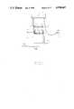
- FIG. 1is a partially cutaway pictorial of a liquid dispensing system incorporating various illustrative embodiments of the invention
- FIG. 2is a pictorial/block diagram showing various illustrative embodiments of the invention.
- FIG. 3is a detailed pictorial diagram showing various features of the present liquid dispensing system including illustrative embodiments of the invention
- FIG. 4is a pictorial showing an exploded diagram of an electronic nozzle assembly of one embodiment of the invention, for example;
- FIG. 5shows a partial sectional view of an illustrative proportional solenoid flow control valve for use in one embodiment of the invention
- FIG. 6shows a block schematic diagram of a microprocessor based controller of another illustrative embodiment of the invention.
- FIG. 7shows a flow chart detailing the overall system operation of one embodiment of the invention.
- FIG. 8shows a flow chart for a monitoring function of an embodiment of the invention
- FIG. 9shows a flow chart for an Interrupt Service Routine (ISR), illustrated as a Timed Interrupt Control Process (TIC) of an embodiment of the invention
- FIG. 10shows a flow chart for the ISR used to service a Z80 Dual A synchronous Receiver Transmitter (DART) external vectored interrupt caused by a state change of the illustrated monostable timer 167 of FIG. 6, of an embodiment of the invention;
- DARTDual A synchronous Receiver Transmitter
- FIG. 11shows a flow chart for a Z80 Counter Timer Circuit (CTC2, i.e. the second of two Z80 CTC circuits) channel 3's Interrupt Service Routine(ISR) of an illustrative embodiment of the invention.
- CTC2Counter Timer Circuit
- ISRInterrupt Service Routine
- FIG. 12shows a duty cycle subroutine for the monitor program loop shown in FIG. 8, in an illustrative embodiment of the invention.
- a dispenser system 1including various embodiments of the invention is shown for purposes of illustration to include a high silouhette housing 3, a sub-housing 5 enclosing the control electronics for the system, in which an accessible key pad 7 and a display panel 9 are mounted, a lower storage housing in which various electromechanical and mechanical devices (to be described in detail below) are enclosed, hollow vertical mounting posts 13 for mounting the control electronic and display housing 5 directly over the lower housing or enclosure 11, with electrical cabling including power and control lines (not shown) being routed through the vertical post 13 between the control housing 5 and the lower housing 11, two main vertical support posts 15 through which product and vapor recovery piping (not shown) are routed to the overhead canopy housing 3, a conduit for conveying liquid such as a relatively small and flexible product hose 17 coupled to product delivery piping (not shown) by appropriate coupling mechanisms located in housing 3, an electrical cable 19 shown in the cutaway section of product hose 17 carries electrical control signals between a relatively lightweight nozzle 21 and the control electronics or controller located within housing 5, an actuator
- the storage boots 29include pump handle switches (not shown) for turning off the dispensing system whenever a nozzle 21 is stowed in a boot 29 (to be described in greater detail below).
- pump handle switchesnot shown
- FIG. 1the liquid or fuel dispensing system shown generally in FIG. 1 is for purposes of illustration only, and many other arrangements may be utilized including various embodiments of the present invention.
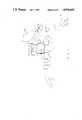
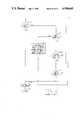
- FIG. 2A generalized block diagram of the invention is shown in FIG. 2, for example.
- a transducer 31is rigidly mounted on the nozzle 21, as shown, or incorporated within the nozzle 21.
- the actuator handle or dispenser control lever 23is pinned via pin 33 to a mounting stud 35 of nozzle 21.
- a plunger 37 of transducer 31rests against the inside surface of actuator 23 as shown.
- the nozzle 21also includes a dispensing spout 39, and a hand guard rail 41.
- the electrical cable 19is routed between the transducer 31 and an electronic controller 43.
- the controller 43is electrically connected to an electrically operated flow control valve 45.
- dispensing of liquidis initiated by an operator lifting up actuator lever 23 against the relatively low resistance of transducer plunger 37, in turn causing the plunger 37 to correspondingly move back into transducer 31.
- Movement of the plunger 37 from its rest, null, or datum positioncauses transducer 31 to output an electrical signal having a magnitude, in this example, proportional to the distance of the plunger 37 or actuator 23 from the rest or datum position.
- the magnitude of the output signal from transducer 31corresponds to a desired flow rate for dispensing liquid from the outlet spout 39 of nozzle 21.
- the controller 43senses the magnitude of the output signal from the transducer 31 at any given time, and outputs a drive or control signal for controlling the degree of opening of the flow control valve 45 for obtaining the desired flow rate for dispensing the liquid received under pressure via the fuel or liquid supply fluid conduit 25.
- the controller 43is located within the control electronic housing 5, and the flow control valve 45 is located within the lower housing 11, remote from the nozzle 21. Accordingly, in this embodiment of the invention, the nozzle 21 can be made relatively light and small compared to prior nozzle assemblies including mechanical valving mechanisms within the nozzle itself for controlling the flow rate of liquid dispensed through the nozzle.
- the product hose 17is free from the relatively high fluid pressures that must be withstood by product hoses in prior systems.
- the product hose 17can be fabricated from a relatively thin walled hose having a relatively small inside and outside diameter, compared to the product hoses of prior systems.
- the nozzle assembly 21 and product hose 17are substantially smaller, of lighter weight, and much easier to manipulate than those of prior systems.
- substantially higher pumping pressures than possible in prior systemscan be utilized in the present invention for providing substantially increased flow rates of fuel than practical in prior systems. Since the flow is controlled by the electrically operated flow control valve 45 rather than manually as in prior systems, the actuation force is only that required to operate the transducer 31. Therefore, the actuation force is substantially reduced and is not increased by increased fluid pressures. Also, the largest pressure drop occurs at valve 45 when the system is off rather in the nozzle 21.
- FIG. 3A more detailed pictorial view of the main components of a dispensing system incorporating various embodiments of the present invention is shown in FIG. 3.
- the display panel 9includes a plurality of displays 49 for, in this example, providing a numeric display of the volume and price of fuel or liquid dispensed at any given time in a dispensing cycle.
- the lowermost display panel 51displays the price per unit quantity for the liquid or fuel selected for dispensing.
- the fuel or liquid supply line 25is connected through a conventional liquid filter 53 to a flow control valve 55 via fluid conduit 57.
- the electrical control 59 of valve 55is electrically connected via a cable 61 to the controller 43 (located in housing 5).
- the valve 55has an inlet 63 coupled to fluid conduit 57, and an outlet 65 coupled to a fluid conduit 60.
- the other end of fluid conduit 57is coupled to an inlet 67 of a flow meter/pulser 69 for providing output pulses indicative of the rate of flow and volume of liquid being dispensed at a given time, via electrical cable 71 to the controller 43.
- the meter/pulser unit 69is, in this example, a Gilbarco Model No.
- PA024TA10manufactured by Gilbarco Inc., of Greensboro, N.C.
- the signal cable 19(routed through or beside or formed within hose 17) is connected through an intrinsically safe electrical connector 73 to another signal cable 75, for electrically connecting the signals from transducer 31 and other electrical devices (to be described below) mounted on nozzle 21 to the controller 43.
- the individual electrical sub-cable 61, 71, and 75are included within the cable assembly 77 running through one of the vertical posts 13 (see FIG. 1).
- the pushbutton 79 for operating a push momentary switch 81 (see FIG. 4) mounted on nozzle 21,is pushed by an operator to latch or lock in a rate of flow of liquid being dispensed at the time of operating the switch 81.
- FIG. 4A detailed pictorial exploded assembly view of an electronic nozzle assembly of one embodiment of the invention is shown in FIG. 4, that was included in an engineering prototype built to test various embodiments of the present invention. This illustration is not meant to be limiting.
- the nozzle spout 81is connected through a fluid conduit coupling 83 to a conventional anti-drain valve 85 having a threaded male portion 87 for mating to coupling 83.
- the inlet of the anti-drain valve 85is connected by a short piece of copper piping 89 to one end of an elbow 91, the other end of the elbow being connected by another piece of copper piping 93, to a nozzle inlet coupling 95, in this example.
- the piping 89 and 93, in spout 81,can be made from any suitable material. Accordingly, in this embodiment of the invention, the main portion of the nozzle 21 is essentially a straight through piece of piping.
- a threaded access hole 97is included in the anti-drain valve housing 85 for receiving an intrinsically safe bulkhead connector 99 through which the signal cable 19 is inserted into the piping 89 and 93, as shown.
- a housing 101fabricated from a suitable material such as a plastic, is rigidly mounted by appropriate means over the portion of the nozzle 21 including the anti-drain valve 85, piping 89, elbow 91, and a portion of the piping 93.
- a trigger or flow actuator assemblyis mounted rigidly to the housing 101, and includes a transducer 103 having a plunger 105, a mounting stud 107 having a hole 109, upon which is mounted an actuator or lever 111 having a hole 113 through which a pin 115 is inserted into and through the hole 109 for securing the lever 111 to the mounting stud 107.
- the transducer 103is oriented to have the plunger 105 in its fully extended condition, and in this example, have its end rest against the upper portion 117 of actuator 111.
- a latching switch 81, a reset switch 119, and an indicator lamp 121are mounted on the housing 101 as shown.
- Individual conductors 123 of the electrical cable 19are individually electrically connected to terminals 125 of transducer 103, terminals 127 of switch 81, terminals 129 of switch 119, and leads 131 of the indicator 121.
- the nozzle assembly 21included a linear position sensor, provided by a typical potentiometer type transducer, in this example. Other types of transducers can also be used for providing the position sensing function of transducer 103.
- the switches 81 and 119were push-momentary conventional switches.
- the nozzle assembly of FIG. 4is operated by an operator pulling back on the actuator 111, causing plunger 105 to be pushed into the body of transducer 103, causing flow rate signals to be supplied to controller 43, as previously described. If the operator wishes to maintain a particular flow rate that is attained at a given time, the operator merely pushes the pushbutton 79 of latching switch 81 to lock in that particular flow rate. However, if after such latching the operator wishes to unlock the selected flow rate, the operator then must push pushbutton 133 of reset switch 119. The signalling from switches 81 and 119 is electrically connected via cable 19 to controller 43 for obtaining the desired functions. Also, the indicator lamp 121 is energized via controller 43 for indicating to an operator that the dispensing system itself is energized at a given time.
- the flow control valve 45can be provided by many known valves.
- the illustrative electrically operated proportional solenoid flow control valve 55includes a proportional solenoid 135 operated via controller 43 for positioning a plunger 135, for in turn positioning a piston 137 for obtaining a desired flow rate for the liquid or fuel being dispensed.
- the plunger 135includes a sealing tip 136, which when pushed against an orifice seat 139 of piston 137, causes the fluid pressure in the control cavity 141 to be greater than the pressure in the central cavity 143, in turn causing the piston 137 to move downward for decreasing the flow rate of liquid or fuel passing therethrough. Conversely, when the plunger 135 moves upward away from the orifice seat 139, the fluid pressure in the central chamber 143 becomes greater than that of the fluid pressure in the control cavity 141, causing piston 137 to move upward lifting throttle 145 away from valve seat 147, increasing the size of the annular gap 149, which in turn increases the rate of flow of liquid or fuel between the inlet port 151 and discharge port 153.
- a control orifice 155provides an open fluid path between the central chamber 143 and control cavity 141 whenever the plunger 135 is positioned with sealing tip 136 away from the orifice seat 139.
- An O-ring seal 157is provided about the throttle 145, as shown, for insuring that the valve is completely closed, preventing any flow of fluid, when piston 137 is moved down to the extreme downwardmost position for closing the valve.
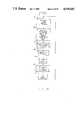
- FIG. 6a block/schematic diagram of the electronic control system, subassemblies, and system components used in the previously mentioned engineering prototype are shown, for purposes of illustration.
- the controller 43includes, a display subassembly 161, a general purpose power supply 163, a pump keypad 165, a monostable timer 167, a valve driver circuit 169, and a Gilbarco Model No. T15897 modified T12C logic board 171 (manufactured by Gilbarco Inc., Greensboro, N.C., the present assignee).
- the logic board 171includes a Z80 microprocessor, two Z80 Counter Timer Circuits (CTC) each with four counter timer channels and two Z80 Dual A synchronous Receiver Transmitters (DART), for example.
- CTCCounter Timer Circuit
- DARTDual A synchronous Receiver Transmitters
- the Z80 microprocessor and associated family of peripheral controllersare linked by a vectored interrupt system. The latter uses a daisy-chain to implement a standard priority interrupt scheme.
- the switch 81, reset switch 119, and indicator lamp 121 of the nozzle assembly 21are electrically connected to the logic board 171.
- the transducer 103in this example a variable potentiometer having a wiper arm movable by movement of plunger 105 attached thereto is connected between a source of voltage +V 2 , and the common connection of a high-pass or filter capacitor 173 and resistor 175 with the monostable timer 167. The other ends of resistor 175 and capacitor 173 are connected to a source of reference potential.
- the transducer or potentiometer 103forms a series voltaqe divider network with resistor 175, for inputting a voltage signal to the monostable timer 167 having a magnitude or voltage level corresponding to the position of the wiper arm/plunger 105 at any given time.
- the monostable timer 167converts the signal voltage obtained from transducer 103 to a corresponding pulse width modulated signal which is connected from an output terminal of the monostable timer 167 to an input terminal of logic board 171.
- the logic board 171applies an appropriate pulse width modulated valve drive signal, in this example, to a valve driver circuit 169 for energizing the solenoid winding 177 of the proportional solenoid flow control valve 55 of FIG. 3, for example.
- pump handle switchessuch as switch 195, for example, are connected to the logic board 171.
- Such pump handles switches 195are located within the storage boots 29 of the dispenser 1 (see FIG. 1).
- the associated pump handle switch 195will be opened, causing logic board 171 to respond by preventing any energization of the associated valve solenoid winding 177.
- the meter/pulser 69is electrically connected to the logic board 171.
- the meter/pulser 69supplies pulses to the logic board indicative of the flow rate and volume of liquid being dispensed at any given time in a dispensing cycle.
- Gilbarco T12C logic boardwas modified in this example, to provide that an input from the monostable timer 171, switch 81, and reset switch 191 are routed to the second DART (DART2) inputs which are capable of generating Z80 system external event vectored interrupts.
- DART2DART2
- Liquid dispensingis initiated by the operator squeezing or moving actuator 111, causing transducer 103 to produce an output voltage that is converted by monostable timer 171 into a pulse width modulated signal, as previously described, which is processed by logic board 171 for providing an appropriate drive signal to the valve driver circuit 169, which in turn energizes solenoid coil 171 for opening the flow control valve 55 to the extent necessary to obtain the called for flow rate.
- This flow ratecan be maintained or locked in by the operator pushing the button 79 of switch 81, for signalling logic board 171 to latch in the flow rate.
- the flow control valve 55is a proportional solenoid control valve 55, permitting the flow rate to be substantially infinitely selectable over a given range of various flow rates.
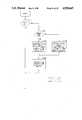
- FIG. 7shows the generalized operation of an embodiment of the present system used on the previously mentioned engineering prototype. Reference is made to steps 701 through 718. Further programming of the preferred embodiment of the invention for programming the Z80 microprocessor of logic board 171 is shown in the flow charts of FIGS. 8 through 12.
- the main programMONITOR
- a number of interrupt and other subroutinesare also programmed into the system, as shown in the flow charts.
- the MONITORdoes not contain interrupt service routine (ISR) call.
- ISRinterrupt service routine
- the main program MONITORincludes a continuous loop of subroutines calls used to service the pump keypad 165, update the display 161, and the proportional flow control valve 55 duty cycle.
- Various subroutines for the keyboard 165 and display servicingare not shown in the various flow charts, in that this programming is standard programming provided off-the-shelf by Gilbarco Inc., Greensboro, N.C., for use on Gilbarco T12C logic boards, such as logic board 171.
- the monostable timer 167is triggered every 125 milliseconds, and uses the flow rate signal voltage from transducer 103 for providing appropriate pulse width modulated signals to the logic board 171, as previously explained.
- the logic board 171is programmed via the CTC2 interrupt routine steps 1101 through 1111, for programming the Z80 CTC to convert the output signal from timer 167 to a pulse width modulated waveform.
- the pulse width modulated waveformis proportional to the width of the output pulse provided by monostable timer 167.
- Fuel flow volume and flow rates from the meter/pulser 69are monitored and used for feedback in controlling the opening of the proportional solenoid valve 55, in this example.
- the results of the various interrupt routinesare used in the subroutine "Duty Cycle" shown in the flow chart of FIG. 12, for setting the pulse width modulated control signal applied to the valve driver circuit 169, and also for providing a damping routine to control changes in the valve drive signals in a manner to avoid oscillation of the valve 55, as previously described.
- a CTC channelis programmed to cause a vectored interrupt every 500 microseconds. Normal program flow is then vectored to an interrupt service routine (ISR) "timed interrupt control process" (TIC).
- ISRinterrupt service routine
- TICtimed interrupt control process
- Various hardware and software clocksare included on the logic board 171, and mention of such clocks is made in the various steps of the TIC process, and other flow chart routines.
- the TIC processincludes steps 901 through 913.
- step 910the value of the variable resistor 104 of transducer 103 is changed due to changes in the corresponding position of plunger 105, corresponding to changes in the position of actuator 111, which effects the level of the voltage across resistor 175 and capacitor 173, and correspondingly causes changes in the timing of the monostable timer 167, as previously explained.
- This flow rate signal voltageaffects the width of the timer 167 output.
- a positive edge of an active low output signal from the monostable timer 167triggers, via logic board 171, a "Dart2" interrupt routine (see FIG. 10), for reading the output of a nozzle time counter (not shown).
- the TIC processis called by an interrupt timer (not shown) every 500 microseconds.
- the timed interrupt or TIC processtriggers the monostable timer 167 to become instable every 125 milliseconds, and uses the flow rate demand signal from transducer 103 for providing appropriate pulse width modulated signals to the logic board 171.
- timer 167returns to its stable state, it causes the Dart2 routine to be initiated by an external interrupt.
- the length of time that the timer 167 remains in a instable stateis controlled via an RC timing circuit formed by resistors 103 and 175, and capacitor 173 (see FIG. 6).
- step 1000a level change on any of the DART2 external interrupt lines (not shown) causes a vectored interrupt to this service routine.
- normal programming flowis temporarily terminated until the Dart2 routine is completed.
- the Dart2 routinesaves the counter timer circuit (CTC) time which is proportional to the reset time of monostable timer 167.
- the Dart2 routineincludes steps 1000 through 1005.
- a CTC2 channel 3is programmed in the count mode.
- the counter (not shown) inputis fed a 25 kHz signal.
- the countis loaded in a CTC down counter register (not shown).
- the CTC down count register on logic board 171is decremented.
- step 1101a down count of zero by channel 3 of CTC 2 (not shown) causes a vectored interrupt to this service routine.
- this routineis completed, program control is returned to the routine which was interrupted.
- the interrupt service routineis then reloaded with an on or off count depending upon whether an on or off count was previously loaded.
- the "ON" and “OFF” timesare maintained by the "Monitor" cycles' "duty cycle” routine shown in the flow chart of FIG.
- the timed output signals from the monostable timer 167are converted to a pulse width modulated waveform via a software routine.
- the "Dutycycle" routineshown in the flow chart of FIG. 12, includes steps 1201 through 1221, as shown. Note that in step 1202, the pulse width modulated dutycycle is made proportional to the width of the output pulse from monostable timer 167. Also, in step 1203, in a "pump on” state, a 28 kHz CTC down counter (not shown) on logic board 171 is loaded with a count to form a pulse width modulated valve control signal. Also note that steps 1212 through 1219 represent a damping algorithm to adjust the dutycycle timing to provide the nozzle flow demand indicated by the flow rate signal from transducer 103, while avoiding unstable flow oscillation or oscillation of the valve 55, as previously described.
- transducer 31 of FIG. 2can be provided by an integrated transducer in the nozzle 21, or by some other suitable type of transducer. The entire system could be automated, to eliminate manual control, and so forth.
Landscapes
- Engineering & Computer Science (AREA)
- Mechanical Engineering (AREA)
- Physics & Mathematics (AREA)
- General Physics & Mathematics (AREA)
- Automation & Control Theory (AREA)
- Flow Control (AREA)
- Feeding And Controlling Fuel (AREA)
Abstract
Description
Claims (22)
Priority Applications (5)
| Application Number | Priority Date | Filing Date | Title |
|---|---|---|---|
| US07/246,673US4930665A (en) | 1988-09-19 | 1988-09-19 | Liquid dispensing system with electronically controlled valve remote from nozzle |
| EP19890309092EP0360464A3 (en) | 1988-09-19 | 1989-09-07 | Liquid dispensing system |
| AU41425/89AAU4142589A (en) | 1988-09-19 | 1989-09-18 | Liquid dispensing system |
| JP24326189AJPH02191200A (en) | 1988-09-19 | 1989-09-19 | Liquid distributor |
| DK461889ADK461889A (en) | 1988-09-19 | 1989-09-19 | liquid dispenser |
Applications Claiming Priority (1)
| Application Number | Priority Date | Filing Date | Title |
|---|---|---|---|
| US07/246,673US4930665A (en) | 1988-09-19 | 1988-09-19 | Liquid dispensing system with electronically controlled valve remote from nozzle |
Publications (1)
| Publication Number | Publication Date |
|---|---|
| US4930665Atrue US4930665A (en) | 1990-06-05 |
Family
ID=22931703
Family Applications (1)
| Application Number | Title | Priority Date | Filing Date |
|---|---|---|---|
| US07/246,673Expired - LifetimeUS4930665A (en) | 1988-09-19 | 1988-09-19 | Liquid dispensing system with electronically controlled valve remote from nozzle |
Country Status (1)
| Country | Link |
|---|---|
| US (1) | US4930665A (en) |
Cited By (36)
| Publication number | Priority date | Publication date | Assignee | Title |
|---|---|---|---|---|
| USD334199S (en) | 1991-06-21 | 1993-03-23 | Ballew Edward W | Fuel dispenser |
| USD335673S (en) | 1991-12-18 | 1993-05-18 | William M. Wilson's Sons, Inc. | Fuel dispensing console |
| USH1326H (en) | 1990-12-24 | 1994-07-05 | The United States Of America As Represented By The Secretary Of The Navy | Transient flow loop system |
| US5340969A (en)* | 1991-10-01 | 1994-08-23 | Dresser Industries, Inc. | Method and apparatus for approving transaction card based transactions |
| DE4331568A1 (en)* | 1993-09-16 | 1995-03-23 | Buerkert Gmbh | Pilot operated valve for motor vehicle fuel systems |
| US5612890A (en)* | 1995-05-19 | 1997-03-18 | F C Systems, Inc. | System and method for controlling product dispensation utilizing metered valve apparatus and electronic interconnection map corresponding to plumbing interconnections |
| US5727765A (en)* | 1996-07-16 | 1998-03-17 | Alvern-Norway A/S | Device for preventing damage to a gas pump filler gun |
| USD395052S (en) | 1997-03-14 | 1998-06-09 | Krone Donald R | Interactive video display and select console for vehicle fueling positions |
| USD396047S (en) | 1997-03-14 | 1998-07-14 | Krone Donald R | Vehicle fueling position |
| US5794667A (en)* | 1996-05-17 | 1998-08-18 | Gilbarco Inc. | Precision fuel dispenser |
| US5868179A (en)* | 1997-03-04 | 1999-02-09 | Gilbarco Inc. | Precision fuel dispenser |
| US5871651A (en)* | 1997-04-02 | 1999-02-16 | Gilbarco Inc. | Electronic filter status sensor |
| USD418523S (en)* | 1998-08-31 | 2000-01-04 | Gilbarco Inc. | Fuel dispensing unit |
| US6131768A (en)* | 1999-05-25 | 2000-10-17 | Tokheim Corporation | Multi-fuel dispenser employing a single meter with bypass loop and multiple hoses |
| US6152196A (en)* | 1998-02-27 | 2000-11-28 | Kehoe; Peter A. | Filling and venting system for a fuel tank |
| DE4331515C2 (en)* | 1993-09-16 | 2002-07-18 | Buerkert Gmbh | Pilot operated shut-off valve with backflow preventer |
| US6625519B2 (en) | 2001-10-01 | 2003-09-23 | Veeder-Root Company Inc. | Pump controller for submersible turbine pumps |
| USD553648S1 (en)* | 2006-08-08 | 2007-10-23 | Deltaven, S.A. | Gasoline dispensary |
| US20140110429A1 (en)* | 2012-10-24 | 2014-04-24 | Argosy Technologies | Apparatus for Dispensing Fuel |
| USD745060S1 (en)* | 2014-05-15 | 2015-12-08 | Wayne Fueling Systems Sweden Ab | Fuel dispenser unit |
| US9586805B1 (en) | 2016-10-11 | 2017-03-07 | Fuel Automation Station, LLC | Mobile distribution station with aisle walkway |
| US9718666B2 (en) | 2014-12-12 | 2017-08-01 | Veeder-Root Company | Fuel dispensing nozzle with ultrasonic transducer for regulating fuel flow rates |
| US9790080B1 (en) | 2016-10-11 | 2017-10-17 | Fuel Automation Station, LLC | Mobile distribution station with fail-safes |
| US9815683B1 (en) | 2016-10-11 | 2017-11-14 | Fuel Automation Station, LLC | Method and system for mobile distribution station |
| US9981840B2 (en) | 2016-10-11 | 2018-05-29 | Fuel Automation Station, LLC | Mobile distribution station having sensor communication lines routed with hoses |
| US10150662B1 (en) | 2017-10-27 | 2018-12-11 | Fuel Automation Station, Llc. | Mobile distribution station with additive injector |
| US10289126B2 (en) | 2016-10-11 | 2019-05-14 | Fuel Automation Station, LLC | Mobile distribution station with guided wave radar fuel level sensors |
| US10633243B2 (en) | 2017-02-24 | 2020-04-28 | Fuel Automation Station, Llc. | Mobile distribution station |
| US10830031B2 (en) | 2018-08-24 | 2020-11-10 | Fuel Automation Station, Llc. | Mobile distribution station having satellite dish |
| US10926996B2 (en) | 2018-05-04 | 2021-02-23 | Fuel Automation Station, Llc. | Mobile distribution station having adjustable feed network |
| US11142449B2 (en) | 2020-01-02 | 2021-10-12 | Fuel Automation Station, LLC | Method and system for dispensing fuel using side-diverting fuel outlets |
| US20230014660A1 (en)* | 2019-12-20 | 2023-01-19 | Wayne Fueling Systems Sweden Ab | Fuel Dispenser with Control System Inside the Hydraulic Compartment |
| US11827421B2 (en) | 2020-01-17 | 2023-11-28 | Fuel Automation Station, LLC | Fuel cap assembly with cylindrical coupler |
| US11993507B2 (en) | 2022-07-19 | 2024-05-28 | 7-Eleven, Inc. | Anomaly detection and controlling fuel dispensing operations using fuel volume determinations |
| US12006203B2 (en) | 2022-07-19 | 2024-06-11 | 7-Eleven, Inc. | Anomaly detection and controlling operations of fuel dispensing terminal during operations |
| US12421100B2 (en) | 2022-07-19 | 2025-09-23 | 7-Eleven, Inc. | Anomaly detection and controlling fuel dispensing operations using fuel volume determinations |
Citations (26)
| Publication number | Priority date | Publication date | Assignee | Title |
|---|---|---|---|---|
| US2192714A (en)* | 1937-05-20 | 1940-03-05 | Stewart Warner Corp | Electric throttle control |
| US2799466A (en)* | 1956-04-09 | 1957-07-16 | Frederick R Hickerson | Solenoid pilot controlled piston valve |
| US2860266A (en)* | 1957-02-06 | 1958-11-11 | American Metal Climax Inc | Linear actuator |
| US3259154A (en)* | 1965-07-19 | 1966-07-05 | Scherer Albert | Apparatus for dispensing a fluid |
| US3278082A (en)* | 1965-03-17 | 1966-10-11 | Electro Pump | Liquid dispensing mechanism |
| US3380491A (en)* | 1965-03-26 | 1968-04-30 | Emco Wheaton | Universal electric nozzle |
| US3424951A (en)* | 1964-11-23 | 1969-01-28 | Monsanto Co | Electrical control valve |
| US3537475A (en)* | 1968-10-21 | 1970-11-03 | Gen Electric | Valve assembly |
| US3590890A (en)* | 1969-02-03 | 1971-07-06 | Sun Oil Co | Nozzle for liquid-fuel-dispensing apparatus |
| US3662924A (en)* | 1971-02-26 | 1972-05-16 | Gilbert & Barker Mfg Co | Light-controlled fluid dispenser |
| US3916961A (en)* | 1973-03-26 | 1975-11-04 | Lawrence Dilger | Liquid dispensing apparatus |
| US3926405A (en)* | 1974-08-21 | 1975-12-16 | Valcor Eng Corp | Solenoid operated proportional valve |
| US3974879A (en)* | 1975-02-14 | 1976-08-17 | Grumman Aerospace Corporation | Method and apparatus for delivering constant water flow rates to a fire hose at each of a plurality of selectable flow rate settings |
| US4014509A (en)* | 1974-05-31 | 1977-03-29 | Yuken Kogyo Company Limited | Proportional electromagnetic-type direction- and throttle-controlling valve |
| US4059135A (en)* | 1975-11-25 | 1977-11-22 | Suntech, Inc. | Interlock system for a fuel dispensing nozzle |
| US4284212A (en)* | 1977-06-09 | 1981-08-18 | Dresser Industries, Inc. | Pilot actuated diaphragm valve |
| US4314585A (en)* | 1978-08-23 | 1982-02-09 | Hitachi, Ltd. | Proportional type electromagnetic valve |
| US4360127A (en)* | 1979-10-19 | 1982-11-23 | Tokico Ltd. | Apparatus for supplying fluid of predetermined quantity |
| US4428558A (en)* | 1980-02-15 | 1984-01-31 | Nippon Soken, Inc. | Proportional solenoid |
| US4429708A (en)* | 1979-03-22 | 1984-02-07 | Trw Inc. | Fluid flow control |
| US4499920A (en)* | 1982-05-17 | 1985-02-19 | Owens-Illinois, Inc. | Apparatus for controlling a valve |
| US4503994A (en)* | 1979-10-01 | 1985-03-12 | Chevron Research Company | Fiber optic fuel shutoff system |
| US4522237A (en)* | 1981-08-20 | 1985-06-11 | Tokyo Tatsuno Co., Ltd. | Apparatus for dispensing liquids |
| US4556093A (en)* | 1984-02-21 | 1985-12-03 | Jones William E M | Automatic shutoff device |
| US4726492A (en)* | 1983-07-20 | 1988-02-23 | Tokico Ltd. | Fuel supplying apparatus |
| US4793589A (en)* | 1987-06-18 | 1988-12-27 | Gilbarco Inc. | Piston valve with proportional solenoid controlled pilot valve |
- 1988
- 1988-09-19USUS07/246,673patent/US4930665A/ennot_activeExpired - Lifetime
Patent Citations (26)
| Publication number | Priority date | Publication date | Assignee | Title |
|---|---|---|---|---|
| US2192714A (en)* | 1937-05-20 | 1940-03-05 | Stewart Warner Corp | Electric throttle control |
| US2799466A (en)* | 1956-04-09 | 1957-07-16 | Frederick R Hickerson | Solenoid pilot controlled piston valve |
| US2860266A (en)* | 1957-02-06 | 1958-11-11 | American Metal Climax Inc | Linear actuator |
| US3424951A (en)* | 1964-11-23 | 1969-01-28 | Monsanto Co | Electrical control valve |
| US3278082A (en)* | 1965-03-17 | 1966-10-11 | Electro Pump | Liquid dispensing mechanism |
| US3380491A (en)* | 1965-03-26 | 1968-04-30 | Emco Wheaton | Universal electric nozzle |
| US3259154A (en)* | 1965-07-19 | 1966-07-05 | Scherer Albert | Apparatus for dispensing a fluid |
| US3537475A (en)* | 1968-10-21 | 1970-11-03 | Gen Electric | Valve assembly |
| US3590890A (en)* | 1969-02-03 | 1971-07-06 | Sun Oil Co | Nozzle for liquid-fuel-dispensing apparatus |
| US3662924A (en)* | 1971-02-26 | 1972-05-16 | Gilbert & Barker Mfg Co | Light-controlled fluid dispenser |
| US3916961A (en)* | 1973-03-26 | 1975-11-04 | Lawrence Dilger | Liquid dispensing apparatus |
| US4014509A (en)* | 1974-05-31 | 1977-03-29 | Yuken Kogyo Company Limited | Proportional electromagnetic-type direction- and throttle-controlling valve |
| US3926405A (en)* | 1974-08-21 | 1975-12-16 | Valcor Eng Corp | Solenoid operated proportional valve |
| US3974879A (en)* | 1975-02-14 | 1976-08-17 | Grumman Aerospace Corporation | Method and apparatus for delivering constant water flow rates to a fire hose at each of a plurality of selectable flow rate settings |
| US4059135A (en)* | 1975-11-25 | 1977-11-22 | Suntech, Inc. | Interlock system for a fuel dispensing nozzle |
| US4284212A (en)* | 1977-06-09 | 1981-08-18 | Dresser Industries, Inc. | Pilot actuated diaphragm valve |
| US4314585A (en)* | 1978-08-23 | 1982-02-09 | Hitachi, Ltd. | Proportional type electromagnetic valve |
| US4429708A (en)* | 1979-03-22 | 1984-02-07 | Trw Inc. | Fluid flow control |
| US4503994A (en)* | 1979-10-01 | 1985-03-12 | Chevron Research Company | Fiber optic fuel shutoff system |
| US4360127A (en)* | 1979-10-19 | 1982-11-23 | Tokico Ltd. | Apparatus for supplying fluid of predetermined quantity |
| US4428558A (en)* | 1980-02-15 | 1984-01-31 | Nippon Soken, Inc. | Proportional solenoid |
| US4522237A (en)* | 1981-08-20 | 1985-06-11 | Tokyo Tatsuno Co., Ltd. | Apparatus for dispensing liquids |
| US4499920A (en)* | 1982-05-17 | 1985-02-19 | Owens-Illinois, Inc. | Apparatus for controlling a valve |
| US4726492A (en)* | 1983-07-20 | 1988-02-23 | Tokico Ltd. | Fuel supplying apparatus |
| US4556093A (en)* | 1984-02-21 | 1985-12-03 | Jones William E M | Automatic shutoff device |
| US4793589A (en)* | 1987-06-18 | 1988-12-27 | Gilbarco Inc. | Piston valve with proportional solenoid controlled pilot valve |
Cited By (54)
| Publication number | Priority date | Publication date | Assignee | Title |
|---|---|---|---|---|
| USH1326H (en) | 1990-12-24 | 1994-07-05 | The United States Of America As Represented By The Secretary Of The Navy | Transient flow loop system |
| USD334199S (en) | 1991-06-21 | 1993-03-23 | Ballew Edward W | Fuel dispenser |
| US5340969A (en)* | 1991-10-01 | 1994-08-23 | Dresser Industries, Inc. | Method and apparatus for approving transaction card based transactions |
| USD335673S (en) | 1991-12-18 | 1993-05-18 | William M. Wilson's Sons, Inc. | Fuel dispensing console |
| DE4331568C2 (en)* | 1993-09-16 | 2001-10-18 | Buerkert Gmbh | Pilot operated valve for motor vehicle fuel systems |
| DE4331568A1 (en)* | 1993-09-16 | 1995-03-23 | Buerkert Gmbh | Pilot operated valve for motor vehicle fuel systems |
| US5551664A (en)* | 1993-09-16 | 1996-09-03 | Burkert Werke Gmbh & Co. | Pilot controlled valve for motor vehicle tank systems |
| DE4331515C2 (en)* | 1993-09-16 | 2002-07-18 | Buerkert Gmbh | Pilot operated shut-off valve with backflow preventer |
| US5612890A (en)* | 1995-05-19 | 1997-03-18 | F C Systems, Inc. | System and method for controlling product dispensation utilizing metered valve apparatus and electronic interconnection map corresponding to plumbing interconnections |
| US5794667A (en)* | 1996-05-17 | 1998-08-18 | Gilbarco Inc. | Precision fuel dispenser |
| US5727765A (en)* | 1996-07-16 | 1998-03-17 | Alvern-Norway A/S | Device for preventing damage to a gas pump filler gun |
| US5868179A (en)* | 1997-03-04 | 1999-02-09 | Gilbarco Inc. | Precision fuel dispenser |
| US5971042A (en)* | 1997-03-04 | 1999-10-26 | Gilbarco Inc. | Precision fuel dispenser |
| USD395052S (en) | 1997-03-14 | 1998-06-09 | Krone Donald R | Interactive video display and select console for vehicle fueling positions |
| USD396047S (en) | 1997-03-14 | 1998-07-14 | Krone Donald R | Vehicle fueling position |
| US5871651A (en)* | 1997-04-02 | 1999-02-16 | Gilbarco Inc. | Electronic filter status sensor |
| US6152196A (en)* | 1998-02-27 | 2000-11-28 | Kehoe; Peter A. | Filling and venting system for a fuel tank |
| USD418523S (en)* | 1998-08-31 | 2000-01-04 | Gilbarco Inc. | Fuel dispensing unit |
| US6131768A (en)* | 1999-05-25 | 2000-10-17 | Tokheim Corporation | Multi-fuel dispenser employing a single meter with bypass loop and multiple hoses |
| US6625519B2 (en) | 2001-10-01 | 2003-09-23 | Veeder-Root Company Inc. | Pump controller for submersible turbine pumps |
| USD553648S1 (en)* | 2006-08-08 | 2007-10-23 | Deltaven, S.A. | Gasoline dispensary |
| US20140110429A1 (en)* | 2012-10-24 | 2014-04-24 | Argosy Technologies | Apparatus for Dispensing Fuel |
| USD745060S1 (en)* | 2014-05-15 | 2015-12-08 | Wayne Fueling Systems Sweden Ab | Fuel dispenser unit |
| US9718666B2 (en) | 2014-12-12 | 2017-08-01 | Veeder-Root Company | Fuel dispensing nozzle with ultrasonic transducer for regulating fuel flow rates |
| US9815683B1 (en) | 2016-10-11 | 2017-11-14 | Fuel Automation Station, LLC | Method and system for mobile distribution station |
| US10303190B2 (en) | 2016-10-11 | 2019-05-28 | Fuel Automation Station, LLC | Mobile distribution station with guided wave radar fuel level sensors |
| US9586805B1 (en) | 2016-10-11 | 2017-03-07 | Fuel Automation Station, LLC | Mobile distribution station with aisle walkway |
| US9932220B1 (en) | 2016-10-11 | 2018-04-03 | Fuel Automation Station, LLC | Mobile distribution station with aisle walkway |
| US9981840B2 (en) | 2016-10-11 | 2018-05-29 | Fuel Automation Station, LLC | Mobile distribution station having sensor communication lines routed with hoses |
| US10087065B2 (en) | 2016-10-11 | 2018-10-02 | Fuel Automation Station, LLC | Mobile distribution station having sensor communication lines routed with hoses |
| US11261079B2 (en) | 2016-10-11 | 2022-03-01 | Fuel Automation Station, LLC | Mobile distribution station with fail-safes |
| US10196258B2 (en) | 2016-10-11 | 2019-02-05 | Fuel Automation Station, LLC | Method and system for mobile distribution station |
| US10289126B2 (en) | 2016-10-11 | 2019-05-14 | Fuel Automation Station, LLC | Mobile distribution station with guided wave radar fuel level sensors |
| US12091307B2 (en) | 2016-10-11 | 2024-09-17 | Fuel Automation Station, LLC | Mobile distribution station with fail-safes |
| US10494251B2 (en) | 2016-10-11 | 2019-12-03 | Fuel Automation Station, LLC | Mobile distribution station with aisle walkway |
| US10513426B2 (en) | 2016-10-11 | 2019-12-24 | Fuel Automation Station, LLC | Mobile distribution station with fail-safes |
| US10974955B2 (en) | 2016-10-11 | 2021-04-13 | Fuel Automation Station, LLC | Mobile distribution station for fluid dispensing |
| US10705547B2 (en) | 2016-10-11 | 2020-07-07 | Fuel Automation Station, LLC | Mobile distribution station with guided wave radar fuel level sensors |
| US10815118B2 (en) | 2016-10-11 | 2020-10-27 | Fuel Automation Station, LLC | Mobile distribution station having sensor communication lines routed with hoses |
| US9790080B1 (en) | 2016-10-11 | 2017-10-17 | Fuel Automation Station, LLC | Mobile distribution station with fail-safes |
| US10633243B2 (en) | 2017-02-24 | 2020-04-28 | Fuel Automation Station, Llc. | Mobile distribution station |
| US11377341B2 (en) | 2017-10-27 | 2022-07-05 | Fuel Automation Station, LLC | Mobile distribution station with additive injector |
| US10150662B1 (en) | 2017-10-27 | 2018-12-11 | Fuel Automation Station, Llc. | Mobile distribution station with additive injector |
| US10926996B2 (en) | 2018-05-04 | 2021-02-23 | Fuel Automation Station, Llc. | Mobile distribution station having adjustable feed network |
| US10830031B2 (en) | 2018-08-24 | 2020-11-10 | Fuel Automation Station, Llc. | Mobile distribution station having satellite dish |
| US20230014660A1 (en)* | 2019-12-20 | 2023-01-19 | Wayne Fueling Systems Sweden Ab | Fuel Dispenser with Control System Inside the Hydraulic Compartment |
| US11820645B2 (en)* | 2019-12-20 | 2023-11-21 | Wayne Fueling Systems Sweden Ab | Fuel dispenser with control system inside the hydraulic compartment |
| US11142449B2 (en) | 2020-01-02 | 2021-10-12 | Fuel Automation Station, LLC | Method and system for dispensing fuel using side-diverting fuel outlets |
| US11827421B2 (en) | 2020-01-17 | 2023-11-28 | Fuel Automation Station, LLC | Fuel cap assembly with cylindrical coupler |
| US12325558B2 (en) | 2020-01-17 | 2025-06-10 | Fuel Automation Station, LLC | Fuel cap assembly with cylindrical coupler |
| US11993507B2 (en) | 2022-07-19 | 2024-05-28 | 7-Eleven, Inc. | Anomaly detection and controlling fuel dispensing operations using fuel volume determinations |
| US12006203B2 (en) | 2022-07-19 | 2024-06-11 | 7-Eleven, Inc. | Anomaly detection and controlling operations of fuel dispensing terminal during operations |
| US12330927B2 (en) | 2022-07-19 | 2025-06-17 | 7-Eleven, Inc. | Anomaly detection and controlling operations of fuel dispensing terminal during operations |
| US12421100B2 (en) | 2022-07-19 | 2025-09-23 | 7-Eleven, Inc. | Anomaly detection and controlling fuel dispensing operations using fuel volume determinations |
Similar Documents
| Publication | Publication Date | Title |
|---|---|---|
| US4930665A (en) | Liquid dispensing system with electronically controlled valve remote from nozzle | |
| US4934565A (en) | Liquid dispensing system with electronically controlled valve remote from nozzle | |
| EP1440033B1 (en) | Electronic lube gun with master station control | |
| US5615832A (en) | Air regulator control system for powder coating operation | |
| US3323560A (en) | Liquid-dispensing nozzle | |
| EP0258424B1 (en) | Intravenous line valving system | |
| AU2002341599A1 (en) | Electronic lube gun with master station control | |
| US5402913A (en) | Apparatus for the metered dispensing of a flowable medium, especially a lubricant | |
| US5328093A (en) | Water-based plural component spray painting system | |
| PL324616A1 (en) | Polyadic liquid dispenser | |
| EP0360464A2 (en) | Liquid dispensing system | |
| US3369705A (en) | Plural source cleaning apparatus having fluid actuated diaphragmtype proportioning valve | |
| EP0251793B1 (en) | Improved liquid dispensing arrangement | |
| EP0719235A4 (en) | Liquid dispensing apparatus | |
| US7296708B2 (en) | Membrane and solenoid actuated valve for dispensing | |
| US6332559B1 (en) | Liquor dispensing apparatus | |
| US5450759A (en) | Airflow indicator | |
| JPH0193686A (en) | flow control valve | |
| AU677366B2 (en) | Dispenser | |
| AU4544397A (en) | Liquor dispensing apparatus | |
| WO1983002561A1 (en) | Flow control for intravenous solutions | |
| WO2005020703A1 (en) | A dispensing apparatus | |
| AU661832B2 (en) | Dispenser | |
| WO1998016459A1 (en) | Liquor dispensing apparatus | |
| NZ241179A (en) | Liquid dispenser: dispensing prevented if reservoir level too low |
Legal Events
| Date | Code | Title | Description |
|---|---|---|---|
| AS | Assignment | Owner name:GILBARCO INC., 7300 W. FRIENDLY AVENUE, GREENSBORO Free format text:ASSIGNMENT OF ASSIGNORS INTEREST.;ASSIGNOR:DEVINE, GEORGE T.;REEL/FRAME:004982/0117 Effective date:19880812 Owner name:GILBARCO INC., NORTH CAROLINA Free format text:ASSIGNMENT OF ASSIGNORS INTEREST;ASSIGNOR:DEVINE, GEORGE T.;REEL/FRAME:004982/0117 Effective date:19880812 | |
| STCF | Information on status: patent grant | Free format text:PATENTED CASE | |
| AS | Assignment | Owner name:GILBARCO INC. Free format text:CHANGE OF NAME;ASSIGNORS:GILBARCO INC. (INTO);DELPHI COMMUNICATIONS CORPORATION (CHANGED TO);REEL/FRAME:006167/0769 Effective date:19830826 | |
| FPAY | Fee payment | Year of fee payment:4 | |
| FPAY | Fee payment | Year of fee payment:8 | |
| AS | Assignment | Owner name:MARCONI COMMERCE SYSTEMS INC., NORTH CAROLINA Free format text:CHANGE OF NAME;ASSIGNOR:GILBARCO INC.;REEL/FRAME:010589/0269 Effective date:19991206 | |
| FPAY | Fee payment | Year of fee payment:12 | |
| AS | Assignment | Owner name:GILBARCO INC., NORTH CAROLINA Free format text:CHANGE OF NAME;ASSIGNOR:MARCONI COMMERCE SYSTEMS INC.;REEL/FRAME:013177/0660 Effective date:20020215 | |
| FEPP | Fee payment procedure | Free format text:PAYOR NUMBER ASSIGNED (ORIGINAL EVENT CODE: ASPN); ENTITY STATUS OF PATENT OWNER: LARGE ENTITY |