US4930495A - Laryngoscope including a disposable blade and its method of use - Google Patents
Laryngoscope including a disposable blade and its method of useDownload PDFInfo
- Publication number
- US4930495A US4930495AUS07/282,115US28211588AUS4930495AUS 4930495 AUS4930495 AUS 4930495AUS 28211588 AUS28211588 AUS 28211588AUS 4930495 AUS4930495 AUS 4930495A
- Authority
- US
- United States
- Prior art keywords
- blade
- handle
- laryngoscope
- operative
- head portion
- Prior art date
- Legal status (The legal status is an assumption and is not a legal conclusion. Google has not performed a legal analysis and makes no representation as to the accuracy of the status listed.)
- Expired - Lifetime
Links
- 238000000034methodMethods0.000titledescription4
- 230000000717retained effectEffects0.000abstractdescription5
- 230000036512infertilityEffects0.000abstract1
- 239000000463materialSubstances0.000description2
- 229910052751metalInorganic materials0.000description2
- 239000002184metalSubstances0.000description2
- 150000002739metalsChemical class0.000description2
- 210000000214mouthAnatomy0.000description2
- 206010011409Cross infectionDiseases0.000description1
- 206010029803Nosocomial infectionDiseases0.000description1
- 230000002452interceptive effectEffects0.000description1
- 230000014759maintenance of locationEffects0.000description1
- 238000004519manufacturing processMethods0.000description1
- 229910001220stainless steelInorganic materials0.000description1
- 239000010935stainless steelSubstances0.000description1
- 230000001954sterilising effectEffects0.000description1
- 238000004659sterilization and disinfectionMethods0.000description1
- 238000002627tracheal intubationMethods0.000description1
Images

Classifications
- A—HUMAN NECESSITIES
- A61—MEDICAL OR VETERINARY SCIENCE; HYGIENE
- A61B—DIAGNOSIS; SURGERY; IDENTIFICATION
- A61B1/00—Instruments for performing medical examinations of the interior of cavities or tubes of the body by visual or photographical inspection, e.g. endoscopes; Illuminating arrangements therefor
- A61B1/267—Instruments for performing medical examinations of the interior of cavities or tubes of the body by visual or photographical inspection, e.g. endoscopes; Illuminating arrangements therefor for the respiratory tract, e.g. laryngoscopes, bronchoscopes
Definitions
- the present inventionrelates generally to a laryngoscope and more particularly to a laryngoscope which utilizes a specifically designed disposable blade.
- a typical laryngoscope availableincludes an elongated handle, a separate blade for use on the handle, and an arrangement carried partially by the handle and partially by the blade for producing a beam of light in a predetermined direction relative to the blade.
- a primary object of the present inventionis to provide a laryngoscope including a blade which is specifically designed to be disposable.
- Another object of the present inventionis to provide a disposable laryngoscope blade which is economical to manufacture and reliable to use.
- Still another object of the present inventionis to provide a disposable laryngoscope blade and associated handle having means which are designed to cooperate with one another so as to specifically discourage use of the blade more than once, but without interfering with its proper use the first time.
- the cooperating means recited aboveare formed by frangible tabs protruding out on opposite sides of the blade and recesses provided on opposite sides of the handle, for receiving the tabs.
- This cooperating arrangement of tabs and recessesnot only causes the blade to be retained in the handle for a first operative use but causes a component of the blade, specifically, the tab, to be damaged sufficient to discourage use of the blade a second time without preventing it from being used in the proper way the first time.
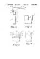
- FIG. 1is a side elevational view of a laryngoscope designed in accordance with the present invention and including a handle and blade, the latter being shown by solid lines in an operative position and by dotted lines in an inoperative position with respect to the handle;
- FIG. 2is a skewed front view of the blade attaching head portion of the handle
- FIG. 3is a rear view of the blade attaching head portion of the handle
- FIG. 4is a cross-sectional view of the blade attaching head portion of the handle, shown in FIG. 3, taken along line 4--4;
- FIG. 5is a side view of the blade, specifically, the handle connecting segment
- FIG. 6is a cross-sectional view of the handle connecting segment of the blade shown in FIG. 5, taken along line 6--6;
- FIG. 7is a rear view of the blade (handle connecting segment) immediately prior to attachment with the handle (blade attaching head portion);
- FIG. 8is a rear view of the blade (handle connecting segment) within the handle (blade attaching head portion).
- the laryngoscope 10comprises two members, a handle 19 and a disposable blade 16, mounted to said handle 19 for movement between an operative position, shown in solid lines, and an inoperative position, shown in phantom.
- laryngoscope 10may be identical to the laryngoscope described in U.S. Pat. No. 4,406,280, except for the way in which the blade 16 is made disposable. For this reason, U.S. Pat. No. 4,406,280 is incorporated herein by reference.
- the handle 19may be functionally divided into two portions, a hand gripping portion 11 and a blade attaching head portion 21.
- the handle 19is preferably made of stainless steel, although other suitable materials include metals, plastic or the like.
- the blade 16 which removably attaches to the handle 19may be functionally divided into two segments, a handle connecting segment 14 and a tongue holding segment 15.
- the handle connecting segment 14mounts to the blade attaching head portion 21 of the handle 19.
- On the blade attaching head portion of the handle 21are means for attaching and retaining the blade 16.
- the attaching means on both the blade 16 and the handle 19remain intact.
- the cooperating retaining means on the handle connecting portion of the blade 14are damaged so as to discourage a second operative use of the blade 16, as will be seen hereinafter.
- Extending frontward from the handle connecting segment of the blade 14is the tongue holding segment 15.
- This blade 16is integrally constructed and is preferably disposable.
- the preferred bladeis made of plastic, but other suitable materials such as metals may be used.
- FIG. 3is a partial side view of the blade attaching portion of the handle 21.
- Two parallel upright structures 22form the top of the blade attaching head portion 21.
- a perpendicular crossbar pin 20extends between the upright structures 22.
- the bladepivotally attaches to the handle 19 at this blade attaching portion 21, about the crossbar pin 20, in the space 24 between the upright structures 22.
- FIG. 4is a cross section along line 4--4 of FIG. 3. This figure shows the inner surface of one of the upright structures 22 of the blade attaching head portion of the handle 21.
- the crossbar pin 20is closest to the front. Proximate to the crossbar pin 20 are recesses 50 which cooperate with means on the blade 16 for retaining the blade 16 within the handle 19 for a first operative use. These recesses 50 also function to damage the blade upon completion of a first operative use when force thereafter is applied to the blade 16 moving it to an inoperative position.
- Crossbar pin 20should preferably be located as far front as possible for pivotal blade attachment.
- Recesses 50may be anywhere along the inside sides of the upright structures 22 of the blade attaching head portion of the handle 21.
- FIG. 5is a side view of the handle connecting segment of the blade.
- the blade illustratedconsists of this segment and the previously recited curved tongue holding segment 15, which is shown in FIG. 1. While a curved tongue holding segment is preferred, this segment can have a multitude of shapes such as rectangular.
- the tongue holding segment 15suppresses the tongue, placing it against the oral cavity floor. This maximizes the free space in the oral cavity, providing the health professional with an unobstructed view of the patient's throat, enabling easier intubation.
- the handle connecting segment 14Rearward from the tongue holding segment 15 is the handle connecting segment 14.
- This handle connecting segment 14comprises a jaw 35 including a slot 31 designed for pivotal engagement with the crossbar pin 20. This design enables a secure engagement during the first proper operative use.
- the handle connecting segment of the blade 14comprises protruding frangible tabs 32, which cooperate with the recesses 50 in the blade attaching head portion of the handle 21 for retaining the blade in a first operative position as will be seen hereinafter with respect to FIGS. 7 and 8.
- the protruding frangible tabs 32can be of any shape and located anywhere on the opposite outside sides of the handle connecting segment of the blade 14 so long as they cooperatingly fit within the recesses 50 of the blade attaching portion of the handle 21 (see FIG. 4) and break away from the rest of the blade 16 in the manner to be described. Triangular tabs are preferred since they easily snap into place and are not damaged upon downward blade attachment and engagement, prior to a first proper operative use, as best seen in FIGS. 7 and 8. However, as the blade 16 is pivoted downward after its first use, with sufficient force, the tabs 32 will break off in order to accommodate this pivotal movement. This is because there is no other way to remove the blade 16. Note specifically in FIG.
- the flat upper surfaces of the tabsengage the upper flat surfaces of recesses 50.
- these tabs 32are integrally formed of plastic along with the rest of the blade 16.
- the tabs 32are such that they can withstand a first attachment and cooperative engagement with the respective recesses 50 on the blade attaching portion of the handle 21, providing sufficient retentive force for a first proper operation of the blade 16.
- the tabs 32are configured to break within the recesses 50 when the blade is 16 is forcibly removed from the handle 19.
- the laryngoscopecan function with as few as one frangible tab and cooperating recess, provided this arrangement yields a retaining force sufficient for a proper first time operative use. Any number of additional frangible tabs may be added, provided there is a correspondingly cooperating recess for each tab.
- FIG. 7is a rear view of the blade as it moves downward for attachment to the handle, for a first time.
- the protruding frangible tabs 32 of the blade 16are forced by a cam like action into the recesses 50 of the handle's upright structures 22.
- Pin 20 of the blade attaching head portion of the handle 21has been omitted for purposes of clarity.
- FIG. 8shows the identical rear view as FIG. 7, but the tabs 32 of the blade 16 are in place within the recesses 50 of the handle 19.
- the health professionalUpon initial attachment to a first inoperative position, the health professional will now push up on the tongue holding segment of the blade 15 until the blade is firmly retained in the handle 19. Retention is maintained by protruding frangible tabs 32 on the blade which cooperate with recesses 50 in the blade attaching head portion of the handle 21. Once the blade 16 is firmly retained in the handle 19, the first operative position is achieved. The health professional may now use the laryngoscope 10 properly for a first and only operative use.
- the health professionalWhen this first operative use is complete, the health professional will disengage the blade 16 from the handle 19. The disengagement process will occur in such a way as to damage the blade 16 discouraging a second operative use.
- Disengagementbegins when downward force is applied to the blade 16, sufficient to overcome the blade retentive force.
- the frangible tabs 32are damaged whereby they are broken off of the blade, sufficiently deformed, or sufficiently weakened. Reduced to remnants, the frangible tabs 32 will no longer fit within the recesses 50 and provide sufficient retentive force for the blade 16. Thus, the damaged blade 16 can not be retained in the handle 19 for a proper second operative use.
- the damaged bladeis now in an inoperative position and can be finally disconnected from the handle 19. Disconnection is achieved by pushing the damaged blade, now in a second inoperative position, rearward, whereby the slot 31 no longer communicates with the crossbar pin 20. The disconnected blade can now be disposed of. A new sterile blade may now be attached for use by the above described method.
Landscapes
- Health & Medical Sciences (AREA)
- Life Sciences & Earth Sciences (AREA)
- Surgery (AREA)
- Radiology & Medical Imaging (AREA)
- Engineering & Computer Science (AREA)
- Pulmonology (AREA)
- Biophysics (AREA)
- Nuclear Medicine, Radiotherapy & Molecular Imaging (AREA)
- Optics & Photonics (AREA)
- Pathology (AREA)
- Physiology (AREA)
- Otolaryngology (AREA)
- Physics & Mathematics (AREA)
- Biomedical Technology (AREA)
- Heart & Thoracic Surgery (AREA)
- Medical Informatics (AREA)
- Molecular Biology (AREA)
- Animal Behavior & Ethology (AREA)
- General Health & Medical Sciences (AREA)
- Public Health (AREA)
- Veterinary Medicine (AREA)
- Endoscopes (AREA)
Abstract
Description
Claims (6)
Priority Applications (2)
| Application Number | Priority Date | Filing Date | Title |
|---|---|---|---|
| US07/282,115US4930495A (en) | 1988-12-09 | 1988-12-09 | Laryngoscope including a disposable blade and its method of use |
| PCT/US1989/005432WO1990006078A1 (en) | 1988-12-09 | 1989-12-07 | Laryngoscope and disposable blade |
Applications Claiming Priority (1)
| Application Number | Priority Date | Filing Date | Title |
|---|---|---|---|
| US07/282,115US4930495A (en) | 1988-12-09 | 1988-12-09 | Laryngoscope including a disposable blade and its method of use |
Publications (1)
| Publication Number | Publication Date |
|---|---|
| US4930495Atrue US4930495A (en) | 1990-06-05 |
Family
ID=23080160
Family Applications (1)
| Application Number | Title | Priority Date | Filing Date |
|---|---|---|---|
| US07/282,115Expired - LifetimeUS4930495A (en) | 1988-12-09 | 1988-12-09 | Laryngoscope including a disposable blade and its method of use |
Country Status (2)
| Country | Link |
|---|---|
| US (1) | US4930495A (en) |
| WO (1) | WO1990006078A1 (en) |
Cited By (18)
| Publication number | Priority date | Publication date | Assignee | Title |
|---|---|---|---|---|
| EP0653180A1 (en)* | 1993-11-12 | 1995-05-17 | Truphatek International Ltd. | Single use laryngoscope blade |
| WO1997017885A3 (en)* | 1995-11-15 | 1997-10-09 | Bar Or David | Laryngoscope and disposable blade therefor |
| US5800342A (en)* | 1994-03-18 | 1998-09-01 | Lee; Jai S. | Method of endotracheal intubation |
| US6623425B2 (en) | 2001-07-23 | 2003-09-23 | Cartledge Medical Products, Llc | Modified laryngoscope blade to reduce dental injuries during intubation |
| US20040215062A1 (en)* | 2002-03-15 | 2004-10-28 | Valery Dalle | Laryngoscope blade and handle |
| WO2004096031A1 (en)* | 2003-04-29 | 2004-11-11 | Aircraft Medical Limited | Laryngoscope with means to restrict re-use of blades |
| WO2005082231A1 (en)* | 2004-02-29 | 2005-09-09 | Truphatek International Ltd | Metal laryngoscope blade |
| US20050240081A1 (en)* | 2004-04-22 | 2005-10-27 | The Cleveland Clinic Foundation | Laryngoscope blade |
| US20080004498A1 (en)* | 2004-11-23 | 2008-01-03 | Eugeny Pecherer | Handheld Penknife-Like Laryngoscope |
| US20080177147A1 (en)* | 2007-01-24 | 2008-07-24 | Jonathan Simons | Laryngoscope |
| US20090271286A1 (en)* | 1996-01-22 | 2009-10-29 | Commerce Technology Licensing, L.L.C. | Method and system for customizing marketing services on networks communicating with hypertext tagging conventions |
| US20100022843A1 (en)* | 2007-03-11 | 2010-01-28 | Eugeny Pecherer | Laryngoscopes and rechargeable illumination units for use therewith |
| US20100041953A1 (en)* | 2004-02-29 | 2010-02-18 | Truphatek International Ltd., | Metal laryngoscope blade with illumination assembly |
| US20110060190A1 (en)* | 2007-08-07 | 2011-03-10 | Truphatek International Ltd. | Laryngoscope apparatus with enhanced viewing capability |
| US8512234B2 (en) | 2011-04-07 | 2013-08-20 | Truphatek International Ltd. | Laryngoscope assembly with enhanced viewing capability |
| US20160051781A1 (en)* | 2014-08-21 | 2016-02-25 | Innovative Premiums, Inc. | Intubation device |
| US10244922B2 (en) | 2013-09-03 | 2019-04-02 | Truphatek International Ltd. | Single use laryngoscope handle for use in dual component laryngoscope assembly |
| US12185923B2 (en) | 2019-03-14 | 2025-01-07 | Teleflex Medical Incorporated | Universal laryngoscope blade for both conventional handles and fiber-illuminated handles |
Citations (5)
| Publication number | Priority date | Publication date | Assignee | Title |
|---|---|---|---|---|
| US3878836A (en)* | 1973-08-23 | 1975-04-22 | Products Int Marketing | Disposable speculum for tympanic thermometer |
| US4406280A (en)* | 1981-10-16 | 1983-09-27 | Upsher Michael S | Laryngoscope including a disposable blade and its method of use |
| US4557256A (en)* | 1984-07-23 | 1985-12-10 | Jack Bauman | Examination device with an improved blade connection |
| US4775364A (en)* | 1987-07-10 | 1988-10-04 | Anthony Alles | Non re-useable disposable hypodermic syringe |
| US4808167A (en)* | 1987-01-16 | 1989-02-28 | Pacesetter Infusion, Ltd. | Medication infusion system with disposable pump/battery cassette |
- 1988
- 1988-12-09USUS07/282,115patent/US4930495A/ennot_activeExpired - Lifetime
- 1989
- 1989-12-07WOPCT/US1989/005432patent/WO1990006078A1/enunknown
Patent Citations (5)
| Publication number | Priority date | Publication date | Assignee | Title |
|---|---|---|---|---|
| US3878836A (en)* | 1973-08-23 | 1975-04-22 | Products Int Marketing | Disposable speculum for tympanic thermometer |
| US4406280A (en)* | 1981-10-16 | 1983-09-27 | Upsher Michael S | Laryngoscope including a disposable blade and its method of use |
| US4557256A (en)* | 1984-07-23 | 1985-12-10 | Jack Bauman | Examination device with an improved blade connection |
| US4808167A (en)* | 1987-01-16 | 1989-02-28 | Pacesetter Infusion, Ltd. | Medication infusion system with disposable pump/battery cassette |
| US4775364A (en)* | 1987-07-10 | 1988-10-04 | Anthony Alles | Non re-useable disposable hypodermic syringe |
Cited By (40)
| Publication number | Priority date | Publication date | Assignee | Title |
|---|---|---|---|---|
| US5879304A (en)* | 1993-11-12 | 1999-03-09 | Truphatek International Ltd. | Single use laryngoscope blade |
| EP0653180A1 (en)* | 1993-11-12 | 1995-05-17 | Truphatek International Ltd. | Single use laryngoscope blade |
| US5800342A (en)* | 1994-03-18 | 1998-09-01 | Lee; Jai S. | Method of endotracheal intubation |
| US5840013A (en)* | 1994-03-18 | 1998-11-24 | Lee; Jai S. | Method of introducing a tubular member at a site in the body |
| US5702351A (en)* | 1995-08-23 | 1997-12-30 | Bar-Or; David | Laryngoscope and disposable blade therefor |
| WO1997017885A3 (en)* | 1995-11-15 | 1997-10-09 | Bar Or David | Laryngoscope and disposable blade therefor |
| US20090271286A1 (en)* | 1996-01-22 | 2009-10-29 | Commerce Technology Licensing, L.L.C. | Method and system for customizing marketing services on networks communicating with hypertext tagging conventions |
| US6623425B2 (en) | 2001-07-23 | 2003-09-23 | Cartledge Medical Products, Llc | Modified laryngoscope blade to reduce dental injuries during intubation |
| US20040034281A1 (en)* | 2001-07-23 | 2004-02-19 | Richard Cartledge | Modified laryngoscope blade to reduce dental injuries during intubation |
| US7044910B2 (en) | 2001-07-23 | 2006-05-16 | Cartledge Medical Products, Inc. | Modified laryngoscope blade to reduce dental injuries during intubation |
| US6964637B2 (en)* | 2002-03-15 | 2005-11-15 | Vygon | Laryngoscope blade and handle |
| US20040215062A1 (en)* | 2002-03-15 | 2004-10-28 | Valery Dalle | Laryngoscope blade and handle |
| CN1809311B (en)* | 2003-04-29 | 2012-06-13 | 航空医学有限公司 | Laryngoscope with member limiting re-use of blade |
| EP2106740A1 (en) | 2003-04-29 | 2009-10-07 | Aircraft Medical Limited | Laryngoscope with means to restrict re-use of blades |
| JP2006525056A (en)* | 2003-04-29 | 2006-11-09 | エアクラフト メディカル リミテッド | Laryngoscope with means to limit blade reuse |
| WO2004096031A1 (en)* | 2003-04-29 | 2004-11-11 | Aircraft Medical Limited | Laryngoscope with means to restrict re-use of blades |
| US20070299313A1 (en)* | 2003-04-29 | 2007-12-27 | Mcgrath Matthew J | Laryngoscope With Means to Restrict Re-Use of Blades |
| EP3087906A1 (en)* | 2003-04-29 | 2016-11-02 | Aircraft Medical Limited | Laryngoscope with means to restrict re-use of blades |
| US9687141B2 (en)* | 2003-04-29 | 2017-06-27 | Aircraft Medical Limited | Laryngoscope with means to restrict re-use of blades |
| WO2005082231A1 (en)* | 2004-02-29 | 2005-09-09 | Truphatek International Ltd | Metal laryngoscope blade |
| US20100041953A1 (en)* | 2004-02-29 | 2010-02-18 | Truphatek International Ltd., | Metal laryngoscope blade with illumination assembly |
| US20070129606A1 (en)* | 2004-02-29 | 2007-06-07 | Eugeny Pecherer | Metal laryngoscope blade |
| US7736304B2 (en) | 2004-02-29 | 2010-06-15 | Truphatek International Ltd. | Metal laryngoscope blade |
| US8142353B2 (en) | 2004-02-29 | 2012-03-27 | Truphatek International Ltd. | Metal laryngoscope blade with illumination assembly |
| US20050240081A1 (en)* | 2004-04-22 | 2005-10-27 | The Cleveland Clinic Foundation | Laryngoscope blade |
| US7909759B2 (en) | 2004-11-23 | 2011-03-22 | Truphatek International Ltd | Handheld penknife-like laryngoscope |
| US20080004498A1 (en)* | 2004-11-23 | 2008-01-03 | Eugeny Pecherer | Handheld Penknife-Like Laryngoscope |
| US20100191061A1 (en)* | 2007-01-24 | 2010-07-29 | Zeppelin Designs Inc. | Laryngoscope with disposable blade cover |
| US7695433B2 (en) | 2007-01-24 | 2010-04-13 | Zeppelin Designs, Inc. | Laryngoscope with disposable blade cover |
| US20080177147A1 (en)* | 2007-01-24 | 2008-07-24 | Jonathan Simons | Laryngoscope |
| US8162826B2 (en) | 2007-03-11 | 2012-04-24 | Truphatek International Ltd. | Laryngoscopes and rechargeable illumination units for use therewith |
| US20100022843A1 (en)* | 2007-03-11 | 2010-01-28 | Eugeny Pecherer | Laryngoscopes and rechargeable illumination units for use therewith |
| US20110060190A1 (en)* | 2007-08-07 | 2011-03-10 | Truphatek International Ltd. | Laryngoscope apparatus with enhanced viewing capability |
| US8251898B2 (en) | 2007-08-07 | 2012-08-28 | Truphatek International Ltd | Laryngoscope apparatus with enhanced viewing capability |
| US8512234B2 (en) | 2011-04-07 | 2013-08-20 | Truphatek International Ltd. | Laryngoscope assembly with enhanced viewing capability |
| US10244922B2 (en) | 2013-09-03 | 2019-04-02 | Truphatek International Ltd. | Single use laryngoscope handle for use in dual component laryngoscope assembly |
| US11219353B2 (en) | 2013-09-03 | 2022-01-11 | Truphatek International Ltd. | Single use laryngoscope handle for use in dual component laryngoscope assembly |
| US20160051781A1 (en)* | 2014-08-21 | 2016-02-25 | Innovative Premiums, Inc. | Intubation device |
| US9821131B2 (en)* | 2014-08-21 | 2017-11-21 | Innovative Premiums, Inc. | Intubation device |
| US12185923B2 (en) | 2019-03-14 | 2025-01-07 | Teleflex Medical Incorporated | Universal laryngoscope blade for both conventional handles and fiber-illuminated handles |
Also Published As
| Publication number | Publication date |
|---|---|
| WO1990006078A1 (en) | 1990-06-14 |
Similar Documents
| Publication | Publication Date | Title |
|---|---|---|
| US4930495A (en) | Laryngoscope including a disposable blade and its method of use | |
| US4955887A (en) | Optical surgical instrument | |
| JPH0731771Y2 (en) | Surgical stapling device | |
| CN1119130C (en) | A scalpel blade remover | |
| EP0489419A1 (en) | A safety hood for hypodermic needles | |
| EP0517252A1 (en) | Disposable vascular punch | |
| JP2002143078A (en) | Outside tube for endoscope | |
| BRPI0904877A2 (en) | surgical stapler with an intermediate closing position | |
| US9687315B2 (en) | Dental plier design with offsetting jaw and pad elements for assisting in removing upper and lower teeth utilizing the dental plier design | |
| CA2482825A1 (en) | Device and method for improving a user's breathing | |
| EP0956841A3 (en) | Corneal surgical apparatus | |
| JP3596810B2 (en) | Universal cartridge | |
| EP0172419A2 (en) | Mouth retractor | |
| US5255422A (en) | Scalpel blade on-off tool | |
| JP2005040573A (en) | Disposable surgical scalpel | |
| US4930220A (en) | Scalpel blade holder | |
| JPS6244496B2 (en) | ||
| US5244389A (en) | Dental handpiece holder | |
| JPS6033939Y2 (en) | dental handpiece holder | |
| AU2020378707B2 (en) | Extraction device for bone staples | |
| JP2004518435A (en) | Remote protruding mechanism of meat stripper blade | |
| CN218419950U (en) | Hemostatic clamp body for clamping tissue and hemostatic clamp | |
| AU594679B2 (en) | Retinal tack and method for implanting same | |
| US2958130A (en) | Dental appliance | |
| JP3260335B2 (en) | Dental mirror |
Legal Events
| Date | Code | Title | Description |
|---|---|---|---|
| AS | Assignment | Owner name:UPSHER LARYNGOSCOPE CORPORATION, THE, P.O. BOX 110 Free format text:ASSIGNMENT OF ASSIGNORS INTEREST.;ASSIGNOR:UPSHER, MICHAEL S.;REEL/FRAME:005060/0365 Effective date:19890215 | |
| STCF | Information on status: patent grant | Free format text:PATENTED CASE | |
| FEPP | Fee payment procedure | Free format text:PAT HOLDER CLAIMS SMALL ENTITY STATUS - SMALL BUSINESS (ORIGINAL EVENT CODE: SM02); ENTITY STATUS OF PATENT OWNER: SMALL ENTITY | |
| FPAY | Fee payment | Year of fee payment:4 | |
| AS | Assignment | Owner name:MERCURY ENTERPRISES, INC., FLORIDA Free format text:ASSIGNMENT OF ASSIGNORS INTEREST;ASSIGNOR:UPSHER LARYNGOSCOPE CORPORATION, THE;REEL/FRAME:008639/0261 Effective date:19970529 | |
| FPAY | Fee payment | Year of fee payment:8 | |
| FEPP | Fee payment procedure | Free format text:PAYOR NUMBER ASSIGNED (ORIGINAL EVENT CODE: ASPN); ENTITY STATUS OF PATENT OWNER: SMALL ENTITY | |
| FEPP | Fee payment procedure | Free format text:PAYOR NUMBER ASSIGNED (ORIGINAL EVENT CODE: ASPN); ENTITY STATUS OF PATENT OWNER: SMALL ENTITY Free format text:PAYER NUMBER DE-ASSIGNED (ORIGINAL EVENT CODE: RMPN); ENTITY STATUS OF PATENT OWNER: SMALL ENTITY | |
| FPAY | Fee payment | Year of fee payment:12 |