US4928694A - Intravascular blood parameter measurement system - Google Patents
Intravascular blood parameter measurement systemDownload PDFInfo
- Publication number
- US4928694A US4928694AUS07/328,041US32804189AUS4928694AUS 4928694 AUS4928694 AUS 4928694AUS 32804189 AUS32804189 AUS 32804189AUS 4928694 AUS4928694 AUS 4928694A
- Authority
- US
- United States
- Prior art keywords
- blood
- sensors
- probe
- parameters
- transmission means
- Prior art date
- Legal status (The legal status is an assumption and is not a legal conclusion. Google has not performed a legal analysis and makes no representation as to the accuracy of the status listed.)
- Expired - Fee Related
Links
Images

Classifications
- A—HUMAN NECESSITIES
- A61—MEDICAL OR VETERINARY SCIENCE; HYGIENE
- A61B—DIAGNOSIS; SURGERY; IDENTIFICATION
- A61B5/00—Measuring for diagnostic purposes; Identification of persons
- A61B5/68—Arrangements of detecting, measuring or recording means, e.g. sensors, in relation to patient
- A61B5/6846—Arrangements of detecting, measuring or recording means, e.g. sensors, in relation to patient specially adapted to be brought in contact with an internal body part, i.e. invasive
- A61B5/6847—Arrangements of detecting, measuring or recording means, e.g. sensors, in relation to patient specially adapted to be brought in contact with an internal body part, i.e. invasive mounted on an invasive device
- A61B5/6852—Catheters
- A—HUMAN NECESSITIES
- A61—MEDICAL OR VETERINARY SCIENCE; HYGIENE
- A61B—DIAGNOSIS; SURGERY; IDENTIFICATION
- A61B5/00—Measuring for diagnostic purposes; Identification of persons
- A61B5/02—Detecting, measuring or recording for evaluating the cardiovascular system, e.g. pulse, heart rate, blood pressure or blood flow
- A61B5/021—Measuring pressure in heart or blood vessels
- A61B5/0215—Measuring pressure in heart or blood vessels by means inserted into the body
- A61B5/02158—Measuring pressure in heart or blood vessels by means inserted into the body provided with two or more sensor elements
- A—HUMAN NECESSITIES
- A61—MEDICAL OR VETERINARY SCIENCE; HYGIENE
- A61B—DIAGNOSIS; SURGERY; IDENTIFICATION
- A61B5/00—Measuring for diagnostic purposes; Identification of persons
- A61B5/145—Measuring characteristics of blood in vivo, e.g. gas concentration or pH-value ; Measuring characteristics of body fluids or tissues, e.g. interstitial fluid or cerebral tissue
- A61B5/1455—Measuring characteristics of blood in vivo, e.g. gas concentration or pH-value ; Measuring characteristics of body fluids or tissues, e.g. interstitial fluid or cerebral tissue using optical sensors, e.g. spectral photometrical oximeters
- A61B5/1459—Measuring characteristics of blood in vivo, e.g. gas concentration or pH-value ; Measuring characteristics of body fluids or tissues, e.g. interstitial fluid or cerebral tissue using optical sensors, e.g. spectral photometrical oximeters invasive, e.g. introduced into the body by a catheter
Definitions
- At least one feature of the inventionis based, in part, upon the recognition and discovery of the reasons why unacceptable results were often obtained in the in vivo system.
- the oxygen readingsare subject to a "wall effect” in that lower concentration readings are obtained when the oxygen sensor is against the wall of the vessel in which it is placed.
- the concentration of oxygen in the bloodmay be different at the vessel wall than at a more central location within the vessel, or the low level of oxygen in the adjacent tissue may cause the oxygen concentration in the vessel wall to be low compared to the concentration in the blood.
- there is a "clot effect”which reduces the oxygen readings when a clot forms over the oxygen sensor.
- the clotmay also effect other readings, such as by increasing the reading for the concentration of C0 2 and reducing the reading for the pH value.
- the "wall effect” and the “clot effect”are independent, but they can exist at the same time, as well as separately.
- this inventionsolves these problems by keeping the sensors, and in particular, the oxygen sensor from contacting the wall of the vessel in which it is placed. This reduces or eliminates the "wall effect” on the oxygen reading. In addition, it reduces the tendency of the blood to form a clot around the sensors. Accordingly, by keeping the sensors out of contact with the wall of the vessel, these two problems are minimized, and acceptable readings are obtainable.
- the means for keeping the sensor from contacting the wallcan take different forms, it preferably includes a tubular body having an opening, and the sensor is positioned within the tubular body.
- the tubular bodycan advantageously take the form of a catheter.
- the openingis preferably a distal opening at the distal end of the catheter.
- One or more radial aperturesmay be provided in addition to the distal opening, if desired.
- a preferred systemincludes a probe-catheter assembly which comprises a probe including at least one sensor for sensing a parameter of blood and providing a signal in response thereto and elongated transmission means for transmitting the signal from the sensor proximally.
- the sensoris carried by a distal portion of the transmission means.
- the assemblyalso includes the catheter which has a lumen extending therethrough, a proximal end, a distal end and a distal opening at the distal end.
- the cathetercan be used to keep the sensor from contacting the wall of the vessel. This can be advantageously accomplished by attaching the probe to the catheter such that the sensor of the probe is within the lumen of the catheter and adjacent the distal opening of the catheter. With this construction, the sensor is shielded from the wall of the vessel by the catheter but is not located so far back within the catheter that it cannot perform its sensing function.
- a sensor located within a catheter lumencould adequately sense the parameter of interest in blood.
- an anti-clotting solutionsuch as a heparinized saline solution
- the solutionmay be resident in the lumen, i.e., have no net flow into the vessel, but preferably it flows at a very low rate, such as 3 to 8 milliliters per hour, through the lumen and out through the distal opening of the catheter into the blood stream in the vessel.
- a sensor positioned in the lumen where there is an anti-clotting solution, particularly in the path of the distally flowing anti-clotting solutionwould be able to adequately sense the parameters of interest in blood.
- the interfacecould be a plane that simply divides the blood from the anti-clotting solution.
- the interfaceis a zone which has some axial length and which contains a mixture of the blood and the anti-clotting solution.
- the interfacedivides a zone of substantially all blood from a zone containing substantially all anti-clotting solution.
- the anti-clotting solutionmay be supplied to the catheter such that there is a net flow of solution through the distal opening to the vessel, it would be expected that the interface would be entirely outside of, or at the distal end of, the catheter.
- the sensorcan be exposed to blood for at least a portion of time that the interface is moving. This exposure must be sufficient to enable the sensor to provide an accurate signal related to the blood parameter of interest.
- the movement of the interface back and forth in the lumenmay move the interface over the sensor.
- the sensors, and in particular the oxygen sensorcan tolerate some exposure to the mixture of anti-clotting solution and blood in the interface without providing erroneous readings. For example, it has been found that a mixture consisting of 50 percent blood by volume and 50 percent anti-clotting solution by volume yields approximately the same oxygen concentration as the oxygen concentration in a medium consisting essentially of blood.
- Movement of the interface to bathe the sensor within the lumen in bloodcan be brought about in different ways.
- the interfacemay be moved by varying the delivery pressure and/or volume of the anti-clotting solution or providing the introducing system with a volume oscillator and allowing the volume oscillator to move the interface.
- the volume oscillatormay, for example, take the form of a syringe which, in effect, expands and contracts the volume of the introducing system to move the blood back and forth in the lumen without creating a net or average flow in either direction.
- Another technique for moving the blood back and forth in the lumenwhich also enables expansion and contraction of the volume of the introducing system, includes providing the introducing system with some compliance and allowing pressures generated by the patient's heartbeats to move the interface. Consequently, blood is forced to enter the distal opening of the catheter as the blood pressure rises with each beat of the heart. Thus, the interface is caused to flow back and forth in the lumen with the pulsating blood pressure. As a result, the sensor within the lumen is bathed by the back and forth or tidal movement of the blood and can adequately sense and measure the blood parameters of interest.
- the compliance of the introducing systemmay be the natural compliance of the tubing and components of the system and/or a compliant element may be added to the system to provide the desired degree of elasticity.
- the compliant elementcan be of virtually any construction and may be, or include for example, a compressible fluid, such as air, a membrane, a bellows, etc.
- the compliance of the introducing systemmay be varied to obtain the results desired. For example, if the compliance of the introducing system is to be used to obtain, or to assist in obtaining, the tidal action, the introducing system and the catheter may have a combined total compliance sufficient to provide a volume exchange of at least 10 microliters with a system comprised of a 20-gauge catheter and 0.022 inch diameter probe.
- the present inventionprovides, as an option, for selectively nullifying the ability of the compliant element to allow expansion and contraction of the volume of the introducing system.
- the nullifying meansmay control expansion or adjustably limit movement of a membrane or bellows or it may selectively switch the compliant element into, and out of, communication with the lumen of the catheter.
- the compliant elementwould normally be in communication with the lumen to provide, or assist in providing, the desirable tidal action for sensing of the blood parameters of interest.
- the action of the compliant elementcan be switched out of the introducing system so that it cannot affect the blood pressure reading taken through the lumen of the catheter.
- the switching meansmay take any form that will accomplish this function and may be, for example, a valve.
- the senorpreferably does not protrude beyond the distal opening of the catheter. It is desirable to have the sensor located proximal to the distal opening of the catheter to provide added insurance against contact with the wall of the vessel. Similarly, the sensor should not be located so far proximal to the distal opening that it cannot adequately sense the parameter of interest. Thus, the sensor should not be so far proximal that it cannot be adequately bathed by the blood. This distance will vary depending on how far the blood is drawn into the lumen. Although the specific distances can vary, for example, placing the sensor between 0.005 inch proximal to the distal opening and 0.125 inch proximal to the distal opening has been found satisfactory. The 0.005 inch dimension is usually sufficient to provide for tolerance variations that, if added together, might cause the sensor to protrude from the lumen.
- the probemay carry one or more sensors depending upon the number of parameters of interest. These sensors can be of any type, such as electro-chemical, that is suitable for sensing the parameter of interest; however, optical sensors are preferred, and fluorescent sensors are considered optimum. Although multiple sensors could be provided to sense the same blood parameter, preferably, each sensor senses a different blood parameter.
- the transmission meansincludes an optical fiber for each of the sensors, with the sensor being located on the distal end of the associated optical fiber. The sensors provide signals related to the associated blood parameters of interest, and such signals may be used or processed continuously, intermittently or on demand to provide readings indicative of the blood parameters of interest.
- a conventional catheter usable with this inventionhas a standard lead-in taper, i.e., the cross-sectional area of the lumen reduces toward the distal opening in a zone closely adjacent the distal opening.
- the presence of the probe in this tapered zonetends to reduce the remaining open area of the lumen to the extent that the monitoring of blood pressure through the lumen is adversely affected.
- this inventionprovides for positioning the sensors at different longitudinal locations along the distal portion of the transmission means. In the specific case of utilizing an optical fiber for each sensor, the optical fibers terminate distally at staggered locations. Consequently, not all of the sensors are located in the tapered zone, and a larger open area of the tapered zone remains for pressure sensing.
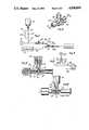
- FIG. 1is a schematic view of an assembly for the in vivo measurement of blood parameters of interest.
- FIG. 2is a perspective view of one form of valve usable in the assembly of FIG. 1.
- FIG. 3is an axial sectional view through the valve with the compliant element being in communication with the conduit leading to the lumen of the catheter.
- FIG. 4is an elevational view partially in section and similar to FIG. 3 with the compliant element being out of communication with the conduit.
- FIG. 5is an enlarged fragmentary sectional view of the distal region of one form of probe and catheter usable in the assembly of FIG. 1.
- FIG. 6is an enlarged sectional view taken generally along line 6--6 of FIG. 5.
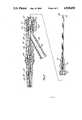
- FIG. 7is a longitudinal sectional view through the probe-catheter assembly.
- FIG. 8is a sectional view similar to FIG. 5 showing an alternate construction of the distal region of the probe.
- FIG. 9is a schematic view similar to FIG. 1 showing another assembly for the in vivo measurement of blood parameters of interest.
- FIG. 1shows an assembly 11 for the in vivo measurement of various blood parameters, and particularly the pH value and the concentrations of oxygen and carbon dioxide.
- the assembly 11can be of different constructions, in this embodiment it includes a solution introducing system 13 and a probe-catheter assembly 15.
- the assembly 11may also include an instrument 17 for providing a readout of the blood parameters of interest.
- the solution introducing system 13introduces an appropriate anti-clotting solution, such as a heparinized saline solution, through the probe-catheter assembly 15 to the patient to keep the line leading to the patient patent.
- an appropriate anti-clotting solutionsuch as a heparinized saline solution
- the system 13includes a pressurized source 19 of heparinized saline solution, a conduit 21 leading from the source to the probe-catheter assembly 15, a flow restrictor 23 to reduce the rate of flow through the conduit 21 to the desired drop rate, a flush valve 25 in a bypass 27 around the restrictor 23, a stop cock 28, a four-way valve 29, a blood withdrawal site 30 and a pressure transducer 31.
- All of the components of the system 13may be conventional, and the system 13 may include other components, if desired.
- solution from the pressurized source 19flows through the restrictor 23 at a relatively slow rate, such as 5 ml/hour.
- the solutionflows through the valve 29 and the probe-catheter assembly 15 to the patient.
- the flush valve 25can be manually opened to provide a relatively high-rate flow path around the restrictor 23 in a conventional manner.
- the four-way valve 29may also be of conventional construction.
- the valve 29includes a valve body 33 having a passage 35 extending therethrough and forming a portion of the conduit 21, a rotatable valve element 37 in the passage 35 and a handle 39 (FIG. 2) for manually rotating the valve element 37.
- the valve body 33has a leg 41, and a closure cap 43 is attached to the leg 41 to define, along with the leg, a chamber 45 in which a compliant element in the form of air is located.
- the valve element 37has ports 47 and 49 for communicating with the conduit 21, and a port 51 which can communicate with the chamber 45 as shown in FIG. 3 or which can be sealed and out of communication with the conduit 21 and the chamber 45 as shown in FIG. 4. In this manner, the compliant element can be switched into, or out of, the system 13.
- the pressure transducer 31communicates with the conduit 21 and can measure the pressure therein. Accordingly, with the probe-catheter assembly 15 inserted into the vascular system of a patient, the pressure transducer 31 can provide blood pressure readings. By rotating the valve element 37 to the position of FIG. 4, the compliance of the air within the chamber 45 cannot affect the blood pressure readings provided by the transducer 31.
- the blood withdrawal site 30is used for taking blood samples from the patient through the probe-catheter assembly 15.
- the stop cock 28is located between the valve 29 and the site 30 so that, by closing the stop cock 28, the air in the chamber 45 cannot be withdrawn during a blood withdrawal procedure.
- the probe-catheter assembly 15includes a catheter 53 and a probe 55 (FIG. 7).
- the catheter 53may be a conventional arterial catheter.
- the catheter 53may include a proximal end 57, a distal end 59, a lumen 61 extending axially, completely through the catheter and opening at a distal opening 63 at the distal end.
- the catheter 53has a standard lead-in taper, i.e., a tapered zone 65, which extends from a reference plane 66 along the outer periphery of the catheter 53 to the distal end 59.
- the diameter of the lumen 61also decreases distally throughout the tapered zone 65 as shown in FIG. 5.
- the tapered zone 65may extend about 0.090 inch proximally of the distal end 59.
- the catheter 53has an externally threaded coupling 67 at its proximal end.
- the probe 55may be of various different constructions, and in the embodiment illustrated, includes an oxygen sensor 69, a carbon dioxide sensor 71 and a pH sensor 73, with each of the sensors affixed to the distal ends of single optical fibers 75, 77, and 79, respectively, (FIG. 6).
- the sensors 69, 71 and 73are fluorescent optical sensors, and they respond to the concentration of oxygen, the concentration of carbon dioxide and the pH value, respectively, to provide continuous optical signals indicative of the condition sensed.
- the optical fibers 75, 77 and 79serve as transmission means for transmitting the signals from the associated sensors proximally.
- the probe 55is of very small cross-sectional area so that it fits within the lumen 61 with an ample radial clearance 81 as shown in FIG. 5.
- the sensors 69, 71 and 73are attached to the distal ends of the associated optical fibers 75, 77 and 79 in any suitable manner, and each of the sensors and the associated fiber is separately encased in an inner overcoat 83 which, among other things, may assist in retaining the sensor on the end of the associated fiber.
- the overcoat 83is, of course, permeable to the relevant blood parameters so that such parameter, or one related to it, can be sensed by the sensors.
- An outer overcoat 85covers the inner overcoats 83 and a length of the fibers just proximally of the overcoats 83.
- the optical fibers 75, 77 and 79 and a temperature-sensitive element, such as a thermocouple 86 (FIG. 6)are suitably encased within an appropriate sheath 87.
- the probe 55includes a "Y" fitting 93 at its proximal end as shown in FIG. 7.
- the optical fibers 75, 77 and 79extend within the sheath 87 completely through one leg 95 of the "Y" fitting 93 to the instrument 17 as shown in FIG. 1.
- Another leg 97 of the fitting 93has a passage 99 which communicates with the lumen 61, and more particularly, with the clearance 81 around the probe 55.
- the leg 97is coupled to the conduit 21 of the system 13 as shown in FIG. 1.
- a third leg 101 of the "Y" fitting 93carries a rotatable internally threaded coupling 103 for attaching the "Y" fitting of the probe 55 to the proximal end of the catheter 53 outside the cardiovascular system of the patient.
- the sheath 87may be guided in the leg 95 by a sleeve 105 and retained in position by potting 107.
- the sheath 87extends within a flexible tube 109 suitably attached to the leg 95, and shrink tubing 111 is provided over the adjacent end portions of the fitting and the tube for strain relief.
- the catheter 53With the proximal end of the catheter 53 coupled to the probe 55 by the coupling 103, the probe 55 is within the lumen 61, and the sensors 69, 71 and 73 are within the lumen adjacent the distal opening 63 as shown in FIG. 5. Accordingly, with the catheter within the cardiovascular system of the patient, such as in a radial artery, the catheter 53 keeps the sensors from contacting the wall of the artery to thereby reduce or eliminate the wall effect and the clot effect on the signals provided by the sensors.
- the catheter 53is first inserted into the radial artery using conventional techniques.
- the probe 55is inserted into the lumen 61 and attached to the proximal end of the catheter 53 with the coupling 103. This properly positions the sensors 69, 71 and 73 within the lumen 61 to within 0.125 inch of the distal end 59.
- a small quantity of airis trapped in the chamber 45. This can be accomplished, for example, with the valve element 37 in the position of FIG. 4, by filling the conduit 21 with solution from the source 19 with the closure cap 43 removed from the valve 29, and without allowing the solution to flow into the leg 41.
- the closure cap 43is then affixed to the leg 41 to trap the air in the chamber 45, and then the rotatable valve element 37 is turned to the position shown in FIG. 3.
- the conduit 21can then be connected to the probe 55.
- the solution from the source 19When in use, the solution from the source 19 completely fills the lumen 61 around the probe 55.
- the solutionis provided under a pressure such that there is a slow flow of solution from the lumen 61 into the patient's artery.
- This introduction of the solution through the lumen and into the arteryresults in an interface 113 adjacent the distal opening 63 which has some axial length and which includes both blood and the solution from the source 19.
- the interface 113is a partition between essentially all blood distally of the interface and essentially all anti-clotting solution proximally of the interface. The interface washes axially back and forth in a tidal action as a result of the rising and falling of the patient's blood pressure with each heartbeat.
- the conduit 21is typically in the form of flexible plastic tubing, which has some elasticity or compliance to allow some of this tidal action to occur.
- the illustrated embodiment of the inventionprovides a compliant element in the form of air within the chamber 45 which adds additional elasticity or compliance to the system 13. Consequently, the interface can flow back and forth to bathe the sensors 69, 71 and 73 in blood.
- the back and forth travel of the interface 113is a function of the magnitude of the patient's blood pressure, the compliance of the solution-introducing system 13 and the delivery pressure of the anti-clotting solution.
- the distal region of the interface 113it would be necessary for at least the distal region of the interface 113 to travel distally as far as the distal opening, unless it is possible for some of the solution to migrate through the blood and through the distal opening.
- the flow rate of anti-clotting solution into the bloodstreamis extremely low, the precise manner in which the solution enters the patient's bloodstream and the exact extent of travel of the interface 113 is not known.
- utilizing the tidal action of the interfaceit is possible to bathe the sensors 69, 71 and 73 in blood sufficiently so that accurate readings are obtained, and it is believed that the sensors are in essentially all blood for a majority of the time.
- FIG. 8shows another embodiment of this invention which is identical to the embodiment of FIGS. 1-7 in all respects not shown or described herein. Portions of the embodiment of FIG. 8 corresponding to portions of the embodiment of FIGS. 1-7 are designated by corresponding reference numerals followed by the letter "a.”
- each of the three sensorsterminates at a different axial position within the lumen 61a, and with this construction, the total cross-sectional area of the probe 55a reduces in step-wise fashion from the distal end of the sensor 71a proximally. Consequently, not all of the sensors are in the tapered zone 65a, and a larger cross-sectional area of the tapered zone remains open for pressure sensing via the pressure transducer 31 shown in FIG. 1.
- the carbon dioxide sensor 71ais the most distal sensor, and the oxygen sensor 69a is the most proximal.
- the reason for thisis that carbon dioxide is the most sensitive to being even partially out of the blood, and the oxygen sensor can provide acceptable oxygen readings even in a fifty-fifty mixture of the blood and the anti-clotting solution.
- the sensitivity of the pH sensor 73ais intermediate the sensitivity of the carbon dioxide sensor 71a and the oxygen sensor 73a and so is preferably located intermediate these sensors.
- the radial apertures 121are preferably located proximally of the sensor 73a for the purpose of allowing blood and solution from the lumen 61a to flow out of the apertures.
- One or more of these aperturesmay be provided, and in the embodiment of FIG. 8, two of the apertures are shown.
- the apertures 121may be distributed in axially spaced relationship, as well as circumferentially spaced relationship, along the catheter 53a.
- the apertures 121may also be used in the embodiment of FIGS. 1-7, if desired.
- FIG. 9shows another embodiment of this invention which is identical to the embodiment of FIGS. 1-7 in all respects not shown or described herein. Portions of the embodiment of FIG. 9 corresponding to portions of the embodiment of FIGS. 1-7 are designated by corresponding reference numerals followed by the letter "b.”
- valve 29has been replaced with a volume oscillator 131.
- the volume oscillator 131can take different forms, including that of a conventional syringe, in this embodiment, it is illustrated schematically as including a cylinder 133 in communication with the conduit 21, a piston 135 slidable in the cylinder and a motor 137 for reciprocating the piston 135 through an appropriate reciprocating drive (not shown), such as a cam shaft.
- an appropriate reciprocating drivenot shown
- a chamber 139 below the pistonis enlarged to expand the volume of the introducing system 13b.
- the motor 137can be operated continuously, intermittently or upon demand to create the tidal action. There is no net or average flow of fluid in either direction as a result of reciprocation of the piston 135.
- the volume oscillator 131can also be used with the embodiment of FIG. 8.
Landscapes
- Health & Medical Sciences (AREA)
- Life Sciences & Earth Sciences (AREA)
- Physics & Mathematics (AREA)
- Surgery (AREA)
- General Health & Medical Sciences (AREA)
- Biophysics (AREA)
- Pathology (AREA)
- Engineering & Computer Science (AREA)
- Biomedical Technology (AREA)
- Heart & Thoracic Surgery (AREA)
- Medical Informatics (AREA)
- Molecular Biology (AREA)
- Veterinary Medicine (AREA)
- Animal Behavior & Ethology (AREA)
- Public Health (AREA)
- Cardiology (AREA)
- Optics & Photonics (AREA)
- Spectroscopy & Molecular Physics (AREA)
- Vascular Medicine (AREA)
- Physiology (AREA)
- Measurement Of The Respiration, Hearing Ability, Form, And Blood Characteristics Of Living Organisms (AREA)
- Measuring Pulse, Heart Rate, Blood Pressure Or Blood Flow (AREA)
- Endoscopes (AREA)
- Ultra Sonic Daignosis Equipment (AREA)
- Investigating Or Analysing Biological Materials (AREA)
Abstract
Description
This application is a continuation of application Ser. No. 008,937, filed Jan. 30, 1987 now U.S. Pat. No. 4,830,013.
It is often necessary or desirable to measure various parameters of blood, such as temperature and blood constituents, such as blood gases, pH, other electrolytes and glucose. This can be accomplished in real time using fluorescent sensors. For example, this can be accomplished in an extracorporeal blood loop as shown in Cooper Application Ser. No. 546,493 filed on Oct. 28, 1983, and in vivo as disclosed in Lubbers et al Reissue Pat. No. 31,879. For in vivo sensing, a probe or catheter carrying an appropriate sensor is inserted into a blood vessel of the patient.
One of the most important gases that needs to be sensed is oxygen. One problem with in vivo oxygen sensing is that the readings obtained for the concentrations of oxygen tend to vary over an unacceptably wide range when compared with the results obtained using conventional laboratory techniques for measuring the concentration of oxygen. It has been found that this deviation is in many cases unacceptably large so that the reliability of the in vivo measuring system is called into question.
At least one feature of the invention is based, in part, upon the recognition and discovery of the reasons why unacceptable results were often obtained in the in vivo system. Specifically, I have discovered that the oxygen readings are subject to a "wall effect" in that lower concentration readings are obtained when the oxygen sensor is against the wall of the vessel in which it is placed. Although this invention is not to be limited by any particular theory, one possible reason for the "wall effect" is that the concentration of oxygen in the blood may be different at the vessel wall than at a more central location within the vessel, or the low level of oxygen in the adjacent tissue may cause the oxygen concentration in the vessel wall to be low compared to the concentration in the blood. In addition, there is a "clot effect" which reduces the oxygen readings when a clot forms over the oxygen sensor. The clot may also effect other readings, such as by increasing the reading for the concentration of C02 and reducing the reading for the pH value. The "wall effect" and the "clot effect" are independent, but they can exist at the same time, as well as separately.
Having recognized these two problems, i.e., the "wall effect" and the "clot effect", this invention solves these problems by keeping the sensors, and in particular, the oxygen sensor from contacting the wall of the vessel in which it is placed. This reduces or eliminates the "wall effect" on the oxygen reading. In addition, it reduces the tendency of the blood to form a clot around the sensors. Accordingly, by keeping the sensors out of contact with the wall of the vessel, these two problems are minimized, and acceptable readings are obtainable.
Techniques exist for keeping various in vivo sensors out of contact with the vessel wall; however, none of these are directed toward solving the "wall effect" or the "clot effect." For example, Schuette U.S. Pat. No. 3,529,591, uses a shield around electrodes to confine the electric field seen by the electrodes in an attempt to minimize interference created through contacting the wall of the vessel. U.S. Pat. No. 4,478,222 employs a sensor within a catheter having a radial opening and also is not concerned with the "wall effect" or the "clot effect."
Although the means for keeping the sensor from contacting the wall can take different forms, it preferably includes a tubular body having an opening, and the sensor is positioned within the tubular body. The tubular body can advantageously take the form of a catheter. To facilitate blood flow into the catheter and to minimize the likelihood that the opening will be shut off by contact with the vessel wall, the opening is preferably a distal opening at the distal end of the catheter. One or more radial apertures may be provided in addition to the distal opening, if desired.
The sensor can be mounted within the catheter in any desired way. A preferred system includes a probe-catheter assembly which comprises a probe including at least one sensor for sensing a parameter of blood and providing a signal in response thereto and elongated transmission means for transmitting the signal from the sensor proximally. The sensor is carried by a distal portion of the transmission means. The assembly also includes the catheter which has a lumen extending therethrough, a proximal end, a distal end and a distal opening at the distal end.
When utilizing a probe-catheter assembly of this type, the catheter can be used to keep the sensor from contacting the wall of the vessel. This can be advantageously accomplished by attaching the probe to the catheter such that the sensor of the probe is within the lumen of the catheter and adjacent the distal opening of the catheter. With this construction, the sensor is shielded from the wall of the vessel by the catheter but is not located so far back within the catheter that it cannot perform its sensing function.
It is quite surprising that a sensor located within a catheter lumen could adequately sense the parameter of interest in blood. One reason for this is that it is necessary to introduce an anti-clotting solution, such as a heparinized saline solution, into the lumen from a solution-introducing system. The solution may be resident in the lumen, i.e., have no net flow into the vessel, but preferably it flows at a very low rate, such as 3 to 8 milliliters per hour, through the lumen and out through the distal opening of the catheter into the blood stream in the vessel. It is surprising that a sensor positioned in the lumen where there is an anti-clotting solution, particularly in the path of the distally flowing anti-clotting solution, would be able to adequately sense the parameters of interest in blood.
However, this invention recognizes that there is an interface between the blood and the anti-clotting solution. Theoretically, the interface could be a plane that simply divides the blood from the anti-clotting solution. However, in reality, the interface is a zone which has some axial length and which contains a mixture of the blood and the anti-clotting solution. Thus, the interface divides a zone of substantially all blood from a zone containing substantially all anti-clotting solution.
Because the anti-clotting solution may be supplied to the catheter such that there is a net flow of solution through the distal opening to the vessel, it would be expected that the interface would be entirely outside of, or at the distal end of, the catheter. However, by moving the interface back and forth in the lumen, the sensor can be exposed to blood for at least a portion of time that the interface is moving. This exposure must be sufficient to enable the sensor to provide an accurate signal related to the blood parameter of interest.
The movement of the interface back and forth in the lumen may move the interface over the sensor. However, the sensors, and in particular the oxygen sensor, can tolerate some exposure to the mixture of anti-clotting solution and blood in the interface without providing erroneous readings. For example, it has been found that a mixture consisting of 50 percent blood by volume and 50 percent anti-clotting solution by volume yields approximately the same oxygen concentration as the oxygen concentration in a medium consisting essentially of blood.
Movement of the interface to bathe the sensor within the lumen in blood can be brought about in different ways. For example, the interface may be moved by varying the delivery pressure and/or volume of the anti-clotting solution or providing the introducing system with a volume oscillator and allowing the volume oscillator to move the interface. The volume oscillator may, for example, take the form of a syringe which, in effect, expands and contracts the volume of the introducing system to move the blood back and forth in the lumen without creating a net or average flow in either direction.
Another technique for moving the blood back and forth in the lumen, which also enables expansion and contraction of the volume of the introducing system, includes providing the introducing system with some compliance and allowing pressures generated by the patient's heartbeats to move the interface. Consequently, blood is forced to enter the distal opening of the catheter as the blood pressure rises with each beat of the heart. Thus, the interface is caused to flow back and forth in the lumen with the pulsating blood pressure. As a result, the sensor within the lumen is bathed by the back and forth or tidal movement of the blood and can adequately sense and measure the blood parameters of interest.
The compliance of the introducing system may be the natural compliance of the tubing and components of the system and/or a compliant element may be added to the system to provide the desired degree of elasticity. The compliant element can be of virtually any construction and may be, or include for example, a compressible fluid, such as air, a membrane, a bellows, etc. The compliance of the introducing system may be varied to obtain the results desired. For example, if the compliance of the introducing system is to be used to obtain, or to assist in obtaining, the tidal action, the introducing system and the catheter may have a combined total compliance sufficient to provide a volume exchange of at least 10 microliters with a system comprised of a 20-gauge catheter and 0.022 inch diameter probe.
It may be necessary or desirable to take the patient's blood pressure through the lumen of the catheter while the blood parameters are being sensed. The added compliance of the introducing system may be sufficient to undesirably alter the blood pressure readings taken through the lumen of the catheter. Accordingly, the present invention provides, as an option, for selectively nullifying the ability of the compliant element to allow expansion and contraction of the volume of the introducing system. For example, the nullifying means may control expansion or adjustably limit movement of a membrane or bellows or it may selectively switch the compliant element into, and out of, communication with the lumen of the catheter. In this latter event, the compliant element would normally be in communication with the lumen to provide, or assist in providing, the desirable tidal action for sensing of the blood parameters of interest. However, just prior to taking a blood pressure reading, the action of the compliant element can be switched out of the introducing system so that it cannot affect the blood pressure reading taken through the lumen of the catheter. The switching means may take any form that will accomplish this function and may be, for example, a valve.
To assure that the sensor will not contact the vessel wall, the sensor preferably does not protrude beyond the distal opening of the catheter. It is desirable to have the sensor located proximal to the distal opening of the catheter to provide added insurance against contact with the wall of the vessel. Similarly, the sensor should not be located so far proximal to the distal opening that it cannot adequately sense the parameter of interest. Thus, the sensor should not be so far proximal that it cannot be adequately bathed by the blood. This distance will vary depending on how far the blood is drawn into the lumen. Although the specific distances can vary, for example, placing the sensor between 0.005 inch proximal to the distal opening and 0.125 inch proximal to the distal opening has been found satisfactory. The 0.005 inch dimension is usually sufficient to provide for tolerance variations that, if added together, might cause the sensor to protrude from the lumen.
The probe may carry one or more sensors depending upon the number of parameters of interest. These sensors can be of any type, such as electro-chemical, that is suitable for sensing the parameter of interest; however, optical sensors are preferred, and fluorescent sensors are considered optimum. Although multiple sensors could be provided to sense the same blood parameter, preferably, each sensor senses a different blood parameter. In a preferred construction, the transmission means includes an optical fiber for each of the sensors, with the sensor being located on the distal end of the associated optical fiber. The sensors provide signals related to the associated blood parameters of interest, and such signals may be used or processed continuously, intermittently or on demand to provide readings indicative of the blood parameters of interest.
A conventional catheter usable with this invention has a standard lead-in taper, i.e., the cross-sectional area of the lumen reduces toward the distal opening in a zone closely adjacent the distal opening. The presence of the probe in this tapered zone tends to reduce the remaining open area of the lumen to the extent that the monitoring of blood pressure through the lumen is adversely affected. To address this problem, in the case of multiple sensors, this invention provides for positioning the sensors at different longitudinal locations along the distal portion of the transmission means. In the specific case of utilizing an optical fiber for each sensor, the optical fibers terminate distally at staggered locations. Consequently, not all of the sensors are located in the tapered zone, and a larger open area of the tapered zone remains for pressure sensing.
The invention, together with additional features and advantages thereof, may best be understood by reference to the following description taken in connection with the accompanying illustrative drawing.
FIG. 1 is a schematic view of an assembly for the in vivo measurement of blood parameters of interest.
FIG. 2 is a perspective view of one form of valve usable in the assembly of FIG. 1.
FIG. 3 is an axial sectional view through the valve with the compliant element being in communication with the conduit leading to the lumen of the catheter.
FIG. 4 is an elevational view partially in section and similar to FIG. 3 with the compliant element being out of communication with the conduit.
FIG. 5 is an enlarged fragmentary sectional view of the distal region of one form of probe and catheter usable in the assembly of FIG. 1.
FIG. 6 is an enlarged sectional view taken generally along line 6--6 of FIG. 5.
FIG. 7 is a longitudinal sectional view through the probe-catheter assembly.
FIG. 8 is a sectional view similar to FIG. 5 showing an alternate construction of the distal region of the probe.
FIG. 9 is a schematic view similar to FIG. 1 showing another assembly for the in vivo measurement of blood parameters of interest.
FIG. 1 shows anassembly 11 for the in vivo measurement of various blood parameters, and particularly the pH value and the concentrations of oxygen and carbon dioxide. Although theassembly 11 can be of different constructions, in this embodiment it includes asolution introducing system 13 and a probe-catheter assembly 15. Theassembly 11 may also include aninstrument 17 for providing a readout of the blood parameters of interest.
Generally, thesolution introducing system 13 introduces an appropriate anti-clotting solution, such as a heparinized saline solution, through the probe-catheter assembly 15 to the patient to keep the line leading to the patient patent. Although this can be accomplished in different ways, in the embodiment shown schematically in FIG. 1, thesystem 13 includes apressurized source 19 of heparinized saline solution, aconduit 21 leading from the source to the probe-catheter assembly 15, a flow restrictor 23 to reduce the rate of flow through theconduit 21 to the desired drop rate, aflush valve 25 in abypass 27 around the restrictor 23, astop cock 28, a four-way valve 29, a blood withdrawal site 30 and apressure transducer 31. All of the components of thesystem 13 may be conventional, and thesystem 13 may include other components, if desired. In the illustrated embodiment, solution from thepressurized source 19 flows through the restrictor 23 at a relatively slow rate, such as 5 ml/hour. The solution flows through thevalve 29 and the probe-catheter assembly 15 to the patient. If a more rapid flow rate from thesource 19 is desired, as for example during priming, theflush valve 25 can be manually opened to provide a relatively high-rate flow path around the restrictor 23 in a conventional manner.
The four-way valve 29 may also be of conventional construction. As shown in FIG. 3, thevalve 29 includes avalve body 33 having apassage 35 extending therethrough and forming a portion of theconduit 21, arotatable valve element 37 in thepassage 35 and a handle 39 (FIG. 2) for manually rotating thevalve element 37. Thevalve body 33 has aleg 41, and aclosure cap 43 is attached to theleg 41 to define, along with the leg, achamber 45 in which a compliant element in the form of air is located. Thevalve element 37 hasports conduit 21, and aport 51 which can communicate with thechamber 45 as shown in FIG. 3 or which can be sealed and out of communication with theconduit 21 and thechamber 45 as shown in FIG. 4. In this manner, the compliant element can be switched into, or out of, thesystem 13.
Thepressure transducer 31 communicates with theconduit 21 and can measure the pressure therein. Accordingly, with the probe-catheter assembly 15 inserted into the vascular system of a patient, thepressure transducer 31 can provide blood pressure readings. By rotating thevalve element 37 to the position of FIG. 4, the compliance of the air within thechamber 45 cannot affect the blood pressure readings provided by thetransducer 31. The blood withdrawal site 30 is used for taking blood samples from the patient through the probe-catheter assembly 15. Preferably for this kind of compliant element, thestop cock 28 is located between thevalve 29 and the site 30 so that, by closing thestop cock 28, the air in thechamber 45 cannot be withdrawn during a blood withdrawal procedure.
The probe-catheter assembly 15 includes acatheter 53 and a probe 55 (FIG. 7). Thecatheter 53 may be a conventional arterial catheter. As such, thecatheter 53 may include aproximal end 57, adistal end 59, alumen 61 extending axially, completely through the catheter and opening at adistal opening 63 at the distal end. Thecatheter 53 has a standard lead-in taper, i.e., a taperedzone 65, which extends from areference plane 66 along the outer periphery of thecatheter 53 to thedistal end 59. The diameter of thelumen 61 also decreases distally throughout the taperedzone 65 as shown in FIG. 5. The taperedzone 65 may extend about 0.090 inch proximally of thedistal end 59. Thecatheter 53 has an externally threaded coupling 67 at its proximal end.
Theprobe 55 may be of various different constructions, and in the embodiment illustrated, includes anoxygen sensor 69, a carbon dioxide sensor 71 and apH sensor 73, with each of the sensors affixed to the distal ends of singleoptical fibers sensors optical fibers probe 55 is of very small cross-sectional area so that it fits within thelumen 61 with an ample radial clearance 81 as shown in FIG. 5.
The particular design of theprobe 55 forms no part of this invention because this invention is applicable to probes of various different constructions. Briefly, however, thesensors optical fibers inner overcoat 83 which, among other things, may assist in retaining the sensor on the end of the associated fiber. Theovercoat 83 is, of course, permeable to the relevant blood parameters so that such parameter, or one related to it, can be sensed by the sensors. Anouter overcoat 85 covers theinner overcoats 83 and a length of the fibers just proximally of theovercoats 83. Proximally of theovercoat 85, theoptical fibers appropriate sheath 87.
Theprobe 55 includes a "Y" fitting 93 at its proximal end as shown in FIG. 7. Theoptical fibers sheath 87 completely through oneleg 95 of the "Y" fitting 93 to theinstrument 17 as shown in FIG. 1. Anotherleg 97 of the fitting 93 has apassage 99 which communicates with thelumen 61, and more particularly, with the clearance 81 around theprobe 55. Theleg 97 is coupled to theconduit 21 of thesystem 13 as shown in FIG. 1. Athird leg 101 of the "Y" fitting 93 carries a rotatable internally threadedcoupling 103 for attaching the "Y" fitting of theprobe 55 to the proximal end of thecatheter 53 outside the cardiovascular system of the patient.
Although the details of the fitting 93 form no part of this invention, thesheath 87 may be guided in theleg 95 by asleeve 105 and retained in position by potting 107. Thesheath 87 extends within aflexible tube 109 suitably attached to theleg 95, and shrinktubing 111 is provided over the adjacent end portions of the fitting and the tube for strain relief.
With the proximal end of thecatheter 53 coupled to theprobe 55 by thecoupling 103, theprobe 55 is within thelumen 61, and thesensors distal opening 63 as shown in FIG. 5. Accordingly, with the catheter within the cardiovascular system of the patient, such as in a radial artery, thecatheter 53 keeps the sensors from contacting the wall of the artery to thereby reduce or eliminate the wall effect and the clot effect on the signals provided by the sensors.
In use of theassembly 11, thecatheter 53 is first inserted into the radial artery using conventional techniques. Next, theprobe 55 is inserted into thelumen 61 and attached to the proximal end of thecatheter 53 with thecoupling 103. This properly positions thesensors lumen 61 to within 0.125 inch of thedistal end 59. In priming thesolution introducing system 13 prior to insertion of the catheter into the artery, a small quantity of air is trapped in thechamber 45. This can be accomplished, for example, with thevalve element 37 in the position of FIG. 4, by filling theconduit 21 with solution from thesource 19 with theclosure cap 43 removed from thevalve 29, and without allowing the solution to flow into theleg 41. Theclosure cap 43 is then affixed to theleg 41 to trap the air in thechamber 45, and then therotatable valve element 37 is turned to the position shown in FIG. 3. Theconduit 21 can then be connected to theprobe 55.
When in use, the solution from thesource 19 completely fills thelumen 61 around theprobe 55. The solution is provided under a pressure such that there is a slow flow of solution from thelumen 61 into the patient's artery. This introduction of the solution through the lumen and into the artery results in aninterface 113 adjacent thedistal opening 63 which has some axial length and which includes both blood and the solution from thesource 19. Theinterface 113 is a partition between essentially all blood distally of the interface and essentially all anti-clotting solution proximally of the interface. The interface washes axially back and forth in a tidal action as a result of the rising and falling of the patient's blood pressure with each heartbeat. If thesolution introducing system 13 were perfectly rigid, it would not be possible for the blood to force the solution proximally within thelumen 61 because the solution is essentially incompressible. However, theconduit 21 is typically in the form of flexible plastic tubing, which has some elasticity or compliance to allow some of this tidal action to occur. In addition, the illustrated embodiment of the invention provides a compliant element in the form of air within thechamber 45 which adds additional elasticity or compliance to thesystem 13. Consequently, the interface can flow back and forth to bathe thesensors
With this embodiment of the invention, the back and forth travel of theinterface 113 is a function of the magnitude of the patient's blood pressure, the compliance of the solution-introducingsystem 13 and the delivery pressure of the anti-clotting solution. However, assuming that there is some net flow of the anti-clotting solution out of thedistal opening 63, it would be necessary for at least the distal region of theinterface 113 to travel distally as far as the distal opening, unless it is possible for some of the solution to migrate through the blood and through the distal opening. Because the flow rate of anti-clotting solution into the bloodstream is extremely low, the precise manner in which the solution enters the patient's bloodstream and the exact extent of travel of theinterface 113 is not known. However, utilizing the tidal action of the interface, it is possible to bathe thesensors
FIG. 8 shows another embodiment of this invention which is identical to the embodiment of FIGS. 1-7 in all respects not shown or described herein. Portions of the embodiment of FIG. 8 corresponding to portions of the embodiment of FIGS. 1-7 are designated by corresponding reference numerals followed by the letter "a."
The primary differences between the embodiment of FIG. 8 and FIGS. 1-7 is that thesensors lumen 61a, thesensors 71a and 73a project farther from theovercoat 85a, and there are a plurality of radial apertures 121 in the catheter 53a leading from thelumen 61a adjacent the distal opening 63a of the catheter. In this embodiment, each of the three sensors terminates at a different axial position within thelumen 61a, and with this construction, the total cross-sectional area of the probe 55a reduces in step-wise fashion from the distal end of the sensor 71a proximally. Consequently, not all of the sensors are in the tapered zone 65a, and a larger cross-sectional area of the tapered zone remains open for pressure sensing via thepressure transducer 31 shown in FIG. 1.
In the construction of FIG. 8, preferably the carbon dioxide sensor 71a is the most distal sensor, and theoxygen sensor 69a is the most proximal. The reason for this is that carbon dioxide is the most sensitive to being even partially out of the blood, and the oxygen sensor can provide acceptable oxygen readings even in a fifty-fifty mixture of the blood and the anti-clotting solution. The sensitivity of thepH sensor 73a is intermediate the sensitivity of the carbon dioxide sensor 71a and theoxygen sensor 73a and so is preferably located intermediate these sensors.
The radial apertures 121 are preferably located proximally of thesensor 73a for the purpose of allowing blood and solution from thelumen 61a to flow out of the apertures. One or more of these apertures may be provided, and in the embodiment of FIG. 8, two of the apertures are shown. Of course, the apertures 121 may be distributed in axially spaced relationship, as well as circumferentially spaced relationship, along the catheter 53a. The apertures 121 may also be used in the embodiment of FIGS. 1-7, if desired.
FIG. 9 shows another embodiment of this invention which is identical to the embodiment of FIGS. 1-7 in all respects not shown or described herein. Portions of the embodiment of FIG. 9 corresponding to portions of the embodiment of FIGS. 1-7 are designated by corresponding reference numerals followed by the letter "b."
The only difference between the embodiment of FIG. 9 and FIGS. 1-7 is that thevalve 29 has been replaced with avolume oscillator 131. Although thevolume oscillator 131 can take different forms, including that of a conventional syringe, in this embodiment, it is illustrated schematically as including acylinder 133 in communication with theconduit 21, apiston 135 slidable in the cylinder and amotor 137 for reciprocating thepiston 135 through an appropriate reciprocating drive (not shown), such as a cam shaft. When thepiston 135 is moved upwardly as viewed in FIG. 9, achamber 139 below the piston is enlarged to expand the volume of the introducing system 13b. Conversely, when thepiston 135 moves downwardly, the volume of thechamber 139 is decreased to thereby contract the volume of the introducing system. Of course, expansion of the introducing system 13b pulls the interface 113 (FIG. 5) proximally. Contraction of the introducing system moves the interface distally, with the amount of such movement being a function of the degree to which thevolume oscillator 131 expands and contracts the volume of the introducing system.
Themotor 137 can be operated continuously, intermittently or upon demand to create the tidal action. There is no net or average flow of fluid in either direction as a result of reciprocation of thepiston 135. Of course, thevolume oscillator 131 can also be used with the embodiment of FIG. 8.
Although exemplary embodiments of the invention have been shown or described, many changes, modifications and substitutions may be made by one having ordinary skill in the art without necessarily departing from the spirit and scope of this invention.
Claims (21)
1. A probe for sensing at least one parameter in blood comprising:
first and second optical sensors for sensing at least one parameter in blood selected from the group consisting of blood gases, pH, electrolytes, glucose, and temperature and for providing a signal in response thereto; and
elongated transmission means for transmitting the signals from the first and second sensors proximally;
said first and second sensors being carried by a distal portion of the transmission means with the first and second sensors being at different longitudinal positions along the distal portion of the transmission means; and
said transmission means and said first and second sensors being sized to be received in the cardiovascular system of a patient.
2. A probe as defined in claim 1 wherein said transmission means includes means for transmitting light.
3. A probe as defined in claim 1 wherein said transmission means includes means for transmitting light and said first sensor is a fluorescent sensor.
4. A probe as defined in claim 1 wherein said first and second sensors sense first and second different parameters in blood, respectively, and said first and second parameters are different blood gases.
5. A probe as defined in claim 1 wherein said first and second sensors sense first and second different parameters in blood, respectively, and said first and second parameters are a blood gas and pH, respectively.
6. A probe as defined in claim 1 wherein said transmission means includes first and second elongated optical fibers, each of said first and second optical fibers has a distal end, said first and second sensors are carried by the first and second optical fibers, respectively, adjacent the distal ends thereof, and said first optical fiber extends distally beyond the second optical fiber.
7. A probe as defined in claim 6 wherein said first and second sensors sense first and second different parameters in blood, respectively, and said first and second parameters are different blood gases.
8. A probe as defined in claim 6 wherein said first and second sensors sense first and second different parameters in blood, respectively, and said first and second parameters are a blood gas and pH, respectively.
9. A probe as defined in claim 6 including a third optical sensor for sensing a parameter in blood, said transmission means includes a third elongated optical fiber having a distal end, said third optical sensor being carried by the third optical fiber adjacent the distal end thereof, and said second optical fiber extends distally beyond the third optical fiber.
10. A probe as defined in claim 1 wherein said first and second sensors sense oxygen and carbon dioxide and the first sensor is located proximally of the second sensor.
11. A probe for sensing at least one parameter in blood comprising:
first and second sensors for sensing at least one parameter in blood selected from the group consisting of blood gases, ph, electrolytes, glucose, and temperature and for providing a signal in response thereto; and
first and second elongated optical fibers, each of said first and second optical fibers having a distal end portion which terminates in a distal end, said first and second sensors being optical sensors and being carried by the first and second optical fibers, respectively, adjacent the distal ends thereof;
said first optical fiber extending distally along the distal end portion of the second optical fiber and distally beyond the distal end of the second optical fiber; and
said first and second optical fibers and said first and second sensors being sized to be received in the cardiovascular system of a patient.
12. A probe as defined in claim 11 wherein said first sensor is a fluorescent sensor.
13. A probe as defined in claim 11 wherein said first and second sensors sense first and second different parameters in blood, respectively, and said first and second parameters are different blood gases.
14. A probe as defined in claim 11 wherein said first and second sensors first and second different parameters in blood, respectively, and said first and second parameters are a blood gas and pH, respectively.
15. A probe as defined in claim 11 including a third optical sensor for sensing a parameter in blood and a third elongated optical fiber having a distal end portion which terminates in a distal end, said third optical sensor being carried by the third optical fiber adjacent the distal end thereof, and said second optical fiber extends distally along the distal end portion of the third optical fiber and distally beyond the distal end of the third optical fiber.
16. An assembly for sensing at least one parameter in blood comprising:
a catheter having a lumen extending therethrough and being sized to be received in the cardiovascular system of a patient; and
a probe including first and second optical sensors for sensing at least one parameter in blood selected from the group consisting of blood gases, pH, electrolytes, glucose, and temperature and for providing a signal in response thereto and elongated transmission means for transmitting the signals from the first and second optical sensors proximally, said first and second optical sensors being carried by a distal portion of the transmission means with the first and second optical sensors being at different longitudinal positions along the distal portion of the transmission means, and said elongated transmission means extending into said lumen and said first and second optical sensors being within said lumen.
17. An assembly as defined in claim 16 wherein the lumen has a distal opening and the sensors are adjacent the distal opening.
18. An assembly as defined in claim 17 wherein the lumen is of reducing cross section toward the distal opening in a tapered zone adjacent the distal opening and the first and second sensors are in the tapered zone.
19. A probe for sensing parameters in blood comprising:
first and second sensors for sensing first and second different parameters in blood, respectively, said parameters being selected from the group consisting of blood gases, pH, electrolytes, and temperature and for providing a signal in response thereto; and
elongated transmission means for transmitting the signals from the first and second sensors proximally;
said first and second sensors being carried by a distal portion of the transmission means with the first and second sensors being at different longitudinal positions along the distal portion of the transmission means; and
said transmission means and said first and second sensors being sized to be received in the cardiovascular system of a patient.
20. A probe as defined in claim 19 wherein said first and second parameters are different blood gases.
21. A probe as defined in claim 19 wherein said first and second parameters are a blood gas and pH, respectively.
Priority Applications (1)
| Application Number | Priority Date | Filing Date | Title |
|---|---|---|---|
| US07328041US4928694B1 (en) | 1987-01-30 | 1989-03-23 | Intravascular blood parameter measurement system |
Applications Claiming Priority (2)
| Application Number | Priority Date | Filing Date | Title |
|---|---|---|---|
| US07/008,937US4830013A (en) | 1987-01-30 | 1987-01-30 | Intravascular blood parameter measurement system |
| US07328041US4928694B1 (en) | 1987-01-30 | 1989-03-23 | Intravascular blood parameter measurement system |
Related Parent Applications (1)
| Application Number | Title | Priority Date | Filing Date |
|---|---|---|---|
| US07/008,937DivisionUS4830013A (en) | 1987-01-30 | 1987-01-30 | Intravascular blood parameter measurement system |
Publications (2)
| Publication Number | Publication Date |
|---|---|
| US4928694Atrue US4928694A (en) | 1990-05-29 |
| US4928694B1 US4928694B1 (en) | 1995-06-06 |
Family
ID=21734588
Family Applications (2)
| Application Number | Title | Priority Date | Filing Date |
|---|---|---|---|
| US07/008,937Expired - LifetimeUS4830013A (en) | 1987-01-30 | 1987-01-30 | Intravascular blood parameter measurement system |
| US07328041Expired - Fee RelatedUS4928694B1 (en) | 1987-01-30 | 1989-03-23 | Intravascular blood parameter measurement system |
Family Applications Before (1)
| Application Number | Title | Priority Date | Filing Date |
|---|---|---|---|
| US07/008,937Expired - LifetimeUS4830013A (en) | 1987-01-30 | 1987-01-30 | Intravascular blood parameter measurement system |
Country Status (6)
| Country | Link |
|---|---|
| US (2) | US4830013A (en) |
| EP (3) | EP0536808B1 (en) |
| JP (1) | JP2642651B2 (en) |
| AT (3) | ATE155331T1 (en) |
| CA (1) | CA1338176C (en) |
| DE (3) | DE3872891D1 (en) |
Cited By (53)
| Publication number | Priority date | Publication date | Assignee | Title |
|---|---|---|---|---|
| US5054882A (en)* | 1990-08-10 | 1991-10-08 | Puritan-Bennett Corporation | Multiple optical fiber event sensor and method of manufacture |
| US5166990A (en)* | 1990-08-10 | 1992-11-24 | Puritan-Bennett Corporation | Multiple optical fiber event sensor and method of manufacture |
| US5284138A (en)* | 1991-07-09 | 1994-02-08 | C. R. Bard, Inc. | Apparatus and method for positioning a sensor away from the blood vessel wall |
| US5326531A (en)* | 1992-12-11 | 1994-07-05 | Puritan-Bennett Corporation | CO2 sensor using a hydrophilic polyurethane matrix and process for manufacturing |
| US5341805A (en)* | 1993-04-06 | 1994-08-30 | Cedars-Sinai Medical Center | Glucose fluorescence monitor and method |
| US5743259A (en)* | 1995-02-16 | 1998-04-28 | Wayne State University | Apparatus and method for continuous monitoring of tissue carbon dioxide and pH using capnometric recirculating gas tonometry |
| US20020122793A1 (en)* | 2000-03-08 | 2002-09-05 | Dongfang Liu | Heparinase III and uses thereof |
| US20020128225A1 (en)* | 2000-10-18 | 2002-09-12 | Massachusetts Institute Of Technology | Methods and products related to pulmonary delivery of polysaccharides |
| US20040147845A1 (en)* | 2003-01-23 | 2004-07-29 | Smith Scott R. | pH measuring balloon |
| US20060024664A1 (en)* | 2000-09-12 | 2006-02-02 | Massachusetts Institute Of Technology | Methods and products related to evaluating the quality of a polysaccharide |
| US20060052745A1 (en)* | 2004-09-08 | 2006-03-09 | Van Antwerp Nannette M | Blood contacting sensor |
| US20060105430A1 (en)* | 1998-08-27 | 2006-05-18 | Massachusetts Institute Of Technology | Rationally designed heparinases derived from heparinase I and II and methods of sequencing therewith |
| US7056504B1 (en) | 1998-08-27 | 2006-06-06 | Massachusetts Institute Of Technology | Rationally designed heparinases derived from heparinase I and II |
| US20060229531A1 (en)* | 2005-02-01 | 2006-10-12 | Daniel Goldberger | Blood monitoring system |
| US20070123801A1 (en)* | 2005-11-28 | 2007-05-31 | Daniel Goldberger | Wearable, programmable automated blood testing system |
| US20070179407A1 (en)* | 2005-09-13 | 2007-08-02 | Mark Gordon | Closed blood sampling system with isolated pressure monitoring |
| US20070191716A1 (en)* | 2004-09-29 | 2007-08-16 | Daniel Goldberger | Blood monitoring system |
| US7412332B1 (en) | 1999-04-23 | 2008-08-12 | Massachusetts Institute Of Technology | Method for analyzing polysaccharides |
| US20080200838A1 (en)* | 2005-11-28 | 2008-08-21 | Daniel Goldberger | Wearable, programmable automated blood testing system |
| US20080275324A1 (en)* | 2006-05-23 | 2008-11-06 | Daniel Goldberger | Fluid Access Interface |
| US7608042B2 (en) | 2004-09-29 | 2009-10-27 | Intellidx, Inc. | Blood monitoring system |
| US7615007B2 (en) | 2006-10-04 | 2009-11-10 | Dexcom, Inc. | Analyte sensor |
| US7640048B2 (en) | 2004-07-13 | 2009-12-29 | Dexcom, Inc. | Analyte sensor |
| US7783333B2 (en) | 2004-07-13 | 2010-08-24 | Dexcom, Inc. | Transcutaneous medical device with variable stiffness |
| US7885697B2 (en) | 2004-07-13 | 2011-02-08 | Dexcom, Inc. | Transcutaneous analyte sensor |
| US20110077480A1 (en)* | 2009-03-27 | 2011-03-31 | Intellidx, Inc. | Fluid transfer system and method |
| US8275438B2 (en) | 2006-10-04 | 2012-09-25 | Dexcom, Inc. | Analyte sensor |
| US8287453B2 (en) | 2003-12-05 | 2012-10-16 | Dexcom, Inc. | Analyte sensor |
| US8298142B2 (en) | 2006-10-04 | 2012-10-30 | Dexcom, Inc. | Analyte sensor |
| US8364230B2 (en) | 2006-10-04 | 2013-01-29 | Dexcom, Inc. | Analyte sensor |
| US8364231B2 (en) | 2006-10-04 | 2013-01-29 | Dexcom, Inc. | Analyte sensor |
| US8396528B2 (en) | 2008-03-25 | 2013-03-12 | Dexcom, Inc. | Analyte sensor |
| US8425417B2 (en) | 2003-12-05 | 2013-04-23 | Dexcom, Inc. | Integrated device for continuous in vivo analyte detection and simultaneous control of an infusion device |
| US8425416B2 (en) | 2006-10-04 | 2013-04-23 | Dexcom, Inc. | Analyte sensor |
| US8447376B2 (en) | 2006-10-04 | 2013-05-21 | Dexcom, Inc. | Analyte sensor |
| US8449464B2 (en) | 2006-10-04 | 2013-05-28 | Dexcom, Inc. | Analyte sensor |
| US8478377B2 (en) | 2006-10-04 | 2013-07-02 | Dexcom, Inc. | Analyte sensor |
| US8562558B2 (en) | 2007-06-08 | 2013-10-22 | Dexcom, Inc. | Integrated medicament delivery device for use with continuous analyte sensor |
| US8562528B2 (en) | 2006-10-04 | 2013-10-22 | Dexcom, Inc. | Analyte sensor |
| US8626257B2 (en) | 2003-08-01 | 2014-01-07 | Dexcom, Inc. | Analyte sensor |
| US8886273B2 (en) | 2003-08-01 | 2014-11-11 | Dexcom, Inc. | Analyte sensor |
| US9986942B2 (en) | 2004-07-13 | 2018-06-05 | Dexcom, Inc. | Analyte sensor |
| US10610137B2 (en) | 2005-03-10 | 2020-04-07 | Dexcom, Inc. | System and methods for processing analyte sensor data for sensor calibration |
| US10813577B2 (en) | 2005-06-21 | 2020-10-27 | Dexcom, Inc. | Analyte sensor |
| US10835672B2 (en) | 2004-02-26 | 2020-11-17 | Dexcom, Inc. | Integrated insulin delivery system with continuous glucose sensor |
| US10966609B2 (en) | 2004-02-26 | 2021-04-06 | Dexcom, Inc. | Integrated medicament delivery device for use with continuous analyte sensor |
| US10980461B2 (en) | 2008-11-07 | 2021-04-20 | Dexcom, Inc. | Advanced analyte sensor calibration and error detection |
| US11000215B1 (en) | 2003-12-05 | 2021-05-11 | Dexcom, Inc. | Analyte sensor |
| US11246990B2 (en) | 2004-02-26 | 2022-02-15 | Dexcom, Inc. | Integrated delivery device for continuous glucose sensor |
| US11331022B2 (en) | 2017-10-24 | 2022-05-17 | Dexcom, Inc. | Pre-connected analyte sensors |
| US11350862B2 (en) | 2017-10-24 | 2022-06-07 | Dexcom, Inc. | Pre-connected analyte sensors |
| US11399745B2 (en) | 2006-10-04 | 2022-08-02 | Dexcom, Inc. | Dual electrode system for a continuous analyte sensor |
| US11633133B2 (en) | 2003-12-05 | 2023-04-25 | Dexcom, Inc. | Dual electrode system for a continuous analyte sensor |
Families Citing this family (66)
| Publication number | Priority date | Publication date | Assignee | Title |
|---|---|---|---|---|
| US4951669A (en)* | 1987-01-30 | 1990-08-28 | Minnesota Mining And Manufacturing Company | Blood parameter measurement system |
| US5048525A (en)* | 1987-01-30 | 1991-09-17 | Minnesota Mining And Manufacturing Company | Blood parameter measurement system with compliant element |
| US4989606A (en)* | 1987-01-30 | 1991-02-05 | Minnesota Mining And Manufactoring Company | Intravascular blood gas sensing system |
| US5462052A (en)* | 1987-01-30 | 1995-10-31 | Minnesota Mining And Manufacturing Co. | Apparatus and method for use in measuring a compositional parameter of blood |
| US5178607A (en)* | 1987-07-31 | 1993-01-12 | Lynn Lawrence A | Blood aspiration assembly septum and blunt needle aspirator |
| US5456251A (en) | 1988-08-26 | 1995-10-10 | Mountpelier Investments, S.A. | Remote sensing tonometric catheter apparatus and method |
| US4947845A (en)* | 1989-01-13 | 1990-08-14 | Pacesetter Infusion, Ltd. | Method of maximizing catheter longevity in an implantable medication infusion system |
| US4911168A (en)* | 1989-01-13 | 1990-03-27 | Pacesetter Infusion, Ltd. | Method of screening and selecting intraperitoneal medication infusion pump candidates |
| US5458571A (en)* | 1989-03-17 | 1995-10-17 | Merit Medical Systems, Inc. | System and method for monitoring, displaying and recording balloon catheter condition interval data |
| US5425713A (en)* | 1989-03-17 | 1995-06-20 | Merit Medical Systems, Inc. | System and method for monitoring, displaying and recording balloon catheter condition interval and inflation location data |
| US5449345A (en)* | 1989-03-17 | 1995-09-12 | Merit Medical Systems, Inc. | Detachable and reusable digital control unit for monitoring balloon catheter data in a syringe inflation system |
| US5431629A (en)* | 1989-03-17 | 1995-07-11 | Merit Medical Systems, Inc. | System and method for monitoring, displaying and recording balloon catheter condition interval data |
| US5453091A (en)* | 1989-03-17 | 1995-09-26 | Merit Medical Systems, Inc. | RF transmission module for wirelessly transmitting balloon catheter data in a syringe inflation system |
| US5135488A (en)* | 1989-03-17 | 1992-08-04 | Merit Medical Systems, Inc. | System and method for monitoring, displaying and recording balloon catheter inflation data |
| US5201753A (en)* | 1989-03-17 | 1993-04-13 | Merit Medical Systems, Inc. | Totally self-contained, digitally controlled, disposable syringe inflation system, and method for monitoring, displaying and recording balloon catheter inflation data |
| CA2034285A1 (en)* | 1990-02-09 | 1991-08-10 | Masao Yafuso | Method and system for monitoring of blood constituents in vivo |
| US5175016A (en)* | 1990-03-20 | 1992-12-29 | Minnesota Mining And Manufacturing Company | Method for making gas sensing element |
| US5104623A (en)* | 1990-04-03 | 1992-04-14 | Minnesota Mining And Manufacturing Company | Apparatus and assembly for use in optically sensing a compositional blood parameter |
| US5278072A (en)* | 1990-04-26 | 1994-01-11 | Minnesota Mining And Manufacturing Company | Calibration system and housing |
| US5171029A (en)* | 1990-04-26 | 1992-12-15 | Minnesota Mining And Manufacturing Company | Seal construction for pump apparatus |
| US5057278A (en)* | 1990-04-26 | 1991-10-15 | Minnesota Mining And Manufacturing Company | Sterile loop calibration system |
| US5048537A (en)* | 1990-05-15 | 1991-09-17 | Medex, Inc. | Method and apparatus for sampling blood |
| US5047627A (en)* | 1990-05-18 | 1991-09-10 | Abbott Laboratories | Configuration fiber-optic blood gas sensor bundle and method of making |
| US5124130A (en)* | 1990-05-22 | 1992-06-23 | Optex Biomedical, Inc. | Optical probe |
| US5261892A (en)* | 1990-07-25 | 1993-11-16 | Abbott Laboratories | Sensor delivery device |
| US5176882A (en)* | 1990-12-06 | 1993-01-05 | Hewlett-Packard Company | Dual fiberoptic cell for multiple serum measurements |
| US5409666A (en)* | 1991-08-08 | 1995-04-25 | Minnesota Mining And Manufacturing Company | Sensors and methods for sensing |
| US5271398A (en)* | 1991-10-09 | 1993-12-21 | Optex Biomedical, Inc. | Intra-vessel measurement of blood parameters |
| US5163904A (en)* | 1991-11-12 | 1992-11-17 | Merit Medical Systems, Inc. | Syringe apparatus with attached pressure gauge |
| US5335305A (en)* | 1991-12-19 | 1994-08-02 | Optex Biomedical, Inc. | Optical sensor for fluid parameters |
| US5333609A (en)* | 1992-05-19 | 1994-08-02 | Minnesota Mining And Manufacturing Company | Catheter and probe-catheter assembly |
| CA2096582A1 (en)* | 1992-05-22 | 1993-11-23 | Erich H. Wolf | Reinforced catheter probe |
| US5449344A (en)* | 1992-06-18 | 1995-09-12 | Merit Medical Systems, Inc. | Syringe apparatus with pressure gauge and detachable timer |
| US5259838A (en)* | 1992-06-18 | 1993-11-09 | Merit Medical Systems, Inc. | Syringe apparatus with attached pressure gauge and timer |
| US5335658A (en)* | 1992-06-29 | 1994-08-09 | Minnesota Mining And Manufacturing Company | Intravascular blood parameter sensing system |
| DE4242533A1 (en)* | 1992-12-16 | 1994-06-23 | Erwin Dr Schaefer | Glucose sensor with gas flushing for detections in-vivo |
| US5474743A (en)* | 1993-10-21 | 1995-12-12 | Minnesota Mining And Manufacturing Company | Cation-sensing composite structure and compounds for use therein |
| US5958782A (en)* | 1993-10-21 | 1999-09-28 | Minnesota Mining And Manufacturing Company | Cation-sensing composite structure and compounds for use therein |
| US5522804A (en)* | 1994-02-15 | 1996-06-04 | Lynn; Lawrence A. | Aspiration, mixing, and injection syringe |
| US5472424A (en)* | 1994-04-05 | 1995-12-05 | Merit Medical Systems, Inc. | Syringe with volume displacement apparatus |
| DE4424267C2 (en)* | 1994-07-09 | 1996-07-11 | Hewlett Packard Gmbh | Device for the continuous acquisition of blood parameters |
| US5697366A (en)* | 1995-01-27 | 1997-12-16 | Optical Sensors Incorporated | In situ calibration system for sensors located in a physiologic line |
| US5673694A (en)* | 1995-08-08 | 1997-10-07 | Henry Ford Health System | Method and apparatus for continuous measurement of central venous oxygen saturation |
| US5772255A (en)* | 1995-09-21 | 1998-06-30 | Abbott Laboratories | Tubing connector |
| US5690215A (en) | 1996-07-08 | 1997-11-25 | Optical Sensors Incorporated | Device for maintaining the partial pressure of a dissolved gas in a fluid and related methods of use |
| US5822137A (en)* | 1997-02-27 | 1998-10-13 | Minnesota Mining & Manufacturing Co. | Assembly for retaining optical components |
| US5997818A (en)* | 1997-02-27 | 1999-12-07 | Minnesota Mining And Manufacturing Company | Cassette for tonometric calibration |
| US6009339A (en)* | 1997-02-27 | 1999-12-28 | Terumo Cardiovascular Systems Corporation | Blood parameter measurement device |
| EP0993266B1 (en)* | 1997-02-27 | 2005-10-19 | Terumo Cardiovascular Systems Corporation | Cassette for measuring parameters of blood |
| CA2303803A1 (en)* | 1997-06-17 | 1998-12-23 | Respironics, Inc. | Fetal oximetry system and sensor |
| US5944660A (en)* | 1997-07-08 | 1999-08-31 | Optical Sensors Incorporated | Disposable cartridge assembly with optional integrated temperature control system, and systems containing same |
| US6679906B2 (en)* | 2001-07-13 | 2004-01-20 | Radiant Medical, Inc. | Catheter system with on-board temperature probe |
| US6664111B2 (en)* | 2001-08-22 | 2003-12-16 | 3M Innovative Properties Company | Fluorescence based oxygen sensor systems |
| US20060009740A1 (en)* | 2001-08-28 | 2006-01-12 | Michael Higgins | Multiple lumen catheter having a soft tip |
| US8996090B2 (en)* | 2002-06-03 | 2015-03-31 | Exostat Medical, Inc. | Noninvasive detection of a physiologic parameter within a body tissue of a patient |
| US6684680B2 (en) | 2002-06-03 | 2004-02-03 | Optical Sensors, Inc. | Cartridge for packaging a sensor in a fluid calibrant |
| US7029467B2 (en)* | 2002-07-16 | 2006-04-18 | Edwards Lifesciences Corporation | Multiple lumen catheter having a soft tip |
| US6999809B2 (en)* | 2002-07-16 | 2006-02-14 | Edwards Lifesciences Corporation | Central venous catheter having a soft tip and fiber optics |
| US7036224B2 (en)* | 2003-05-12 | 2006-05-02 | Mamac Systems, Inc. | Method of making fluid sensor probe |
| US20080200788A1 (en)* | 2006-10-04 | 2008-08-21 | Dexcorn, Inc. | Analyte sensor |
| US20070156035A1 (en)* | 2006-01-03 | 2007-07-05 | Salus Corporation D/B/A Icp Medical | Catheter operable to deliver IV fluids and provide blood testing capabilities |
| US20090043184A1 (en)* | 2007-08-08 | 2009-02-12 | Edwards Lifesciences Corporation | Catheter and probe for measuring analytes or other parameters |
| WO2010027771A1 (en) | 2008-08-27 | 2010-03-11 | Edwards Lifesciences Corporation | Analyte sensor |
| AT506798B1 (en) | 2009-01-13 | 2009-12-15 | Smart Medical Solutions Gmbh | DEVICE FOR MEASURING AT LEAST ONE PARAMETER OF AN ARTERIAL BLOOD TEST |
| US10994076B1 (en) | 2019-07-25 | 2021-05-04 | Circulatech, Llc | Methods and devices to prevent obstructions in medical tubes |
| WO2022209703A1 (en)* | 2021-03-31 | 2022-10-06 | テルモ株式会社 | Measurement adapter, measurement system and measurement method |
Citations (33)
| Publication number | Priority date | Publication date | Assignee | Title |
|---|---|---|---|---|
| US2629399A (en)* | 1946-10-16 | 1953-02-24 | Kulick George | Safety valve for regulating and testing light pressures |
| US3498286A (en)* | 1966-09-21 | 1970-03-03 | American Optical Corp | Catheters |
| US3612866A (en)* | 1969-07-08 | 1971-10-12 | Brian Stevens | Instrument for determining oxygen quantities by measuring oxygen quenching of fluorescent radiation |
| US3616409A (en)* | 1968-06-07 | 1971-10-26 | Univ Duke | Electrode system for measuring ion activities in stream or sample |
| US3674013A (en)* | 1970-09-30 | 1972-07-04 | American Optical Corp | Fiberoptic catheter |
| US3807390A (en)* | 1972-12-04 | 1974-04-30 | American Optical Corp | Fiber optic catheter |
| US3866599A (en)* | 1972-01-21 | 1975-02-18 | Univ Washington | Fiberoptic catheter |
| US4050450A (en)* | 1976-03-05 | 1977-09-27 | American Optical Corporation | Reflection standard for fiber optic probe |
| US4073297A (en)* | 1976-02-11 | 1978-02-14 | Sandoz Ltd. | Catheter |
| US4201222A (en)* | 1977-08-31 | 1980-05-06 | Thomas Haase | Method and apparatus for in vivo measurement of blood gas partial pressures, blood pressure and blood pulse |
| US4210029A (en)* | 1979-05-04 | 1980-07-01 | Lad Research Industries, Inc. | Differential fiber optic differential pressure sensor |
| US4295470A (en)* | 1976-10-18 | 1981-10-20 | Oximetrix, Inc. | Optical catheters and method for making same |
| US4311137A (en)* | 1980-04-30 | 1982-01-19 | Sherwood Medical Industries Inc. | Infusion device |
| US4322164A (en)* | 1976-10-18 | 1982-03-30 | Oximetrix, Inc. | Sterilizable, disposable optical scattering reference medium and container assembly |
| US4398542A (en)* | 1980-12-15 | 1983-08-16 | Ivac Corporation | Pressure diaphragm |
| US4407290A (en)* | 1981-04-01 | 1983-10-04 | Biox Technology, Inc. | Blood constituent measuring device and method |
| US4471765A (en)* | 1980-09-25 | 1984-09-18 | The Massachusetts General Hospital | Apparatus for radiolabeling red blood cells |
| US4476877A (en)* | 1982-08-16 | 1984-10-16 | Gould Inc. | Fluid temperature sensor |
| US4502488A (en)* | 1983-01-13 | 1985-03-05 | Allied Corporation | Injection system |
| US4508123A (en)* | 1983-06-01 | 1985-04-02 | American Hospital Supply Corporation | Thermodilution injectate assembly |
| US4557900A (en)* | 1982-09-28 | 1985-12-10 | Cardiovascular Devices, Inc. | Optical sensor with beads |
| US4573968A (en)* | 1983-08-16 | 1986-03-04 | Ivac Corporation | Infusion and blood chemistry monitoring system |
| US4585007A (en)* | 1982-05-15 | 1986-04-29 | Kabushiki Kaisha Kyoto Daiichi Kagaku | Method for continuously measuring a specified ingredient in a diluted liquid |
| US4601706A (en)* | 1984-12-03 | 1986-07-22 | Rene Aillon | Central venous pressure catheter for preventing air embolism and method of making |
| US4608996A (en)* | 1984-08-10 | 1986-09-02 | Cordis Corporation | External blood parameter diagnostic system |
| US4640820A (en)* | 1983-10-28 | 1987-02-03 | Cardiovascular Devices, Inc. | Flow-through housing with blood gas sensors |
| US4651741A (en)* | 1985-05-30 | 1987-03-24 | Baxter Travenol Laboratories, Inc. | Method and apparatus for determining oxygen saturation in vivo |
| US4684245A (en)* | 1985-10-28 | 1987-08-04 | Oximetrix, Inc. | Electro-optical coupler for catheter oximeter |
| US4718423A (en)* | 1986-10-17 | 1988-01-12 | Spectramed, Inc. | Multiple-function cardiovascular catheter system with very high lumenal efficiency and no crossovers |
| US4736748A (en)* | 1986-04-05 | 1988-04-12 | Kuraray Co., Ltd. | Blood component monitoring system |
| US4774955A (en)* | 1986-06-04 | 1988-10-04 | Solutech, Inc. | Programmable dialyzer system analyzer and method of use |
| US4785814A (en)* | 1987-08-11 | 1988-11-22 | Cordis Corporation | Optical probe for measuring pH and oxygen in blood and employing a composite membrane |
| US4810655A (en)* | 1985-07-03 | 1989-03-07 | Abbott Laboratories | Method for measuring oxygen concentration |
Family Cites Families (32)
| Publication number | Priority date | Publication date | Assignee | Title |
|---|---|---|---|---|
| US31879A (en)* | 1861-04-02 | Machine for finishing leatheb | ||
| US3433935A (en)* | 1963-07-12 | 1969-03-18 | Herbert Sherman | Apparatus for computation particularly adapted for producing a measure of transit time and the like |
| GB1084079A (en)* | 1964-11-30 | Beckman Instruments Inc | ||
| US3461856A (en)* | 1965-10-23 | 1969-08-19 | American Optical Corp | Oximeters |
| US3529591A (en)* | 1968-05-16 | 1970-09-22 | Biotronex Lab Inc | Catheter tip blood velocity sensor |
| US3658053A (en)* | 1969-08-28 | 1972-04-25 | Scient Research Instr Corp | Catheter for use in detecting dissolved gas in fluids such as blood |
| US3814081A (en)* | 1971-04-02 | 1974-06-04 | Olympus Optical Co | Optical measuring catheter |
| US3878830A (en)* | 1973-05-31 | 1975-04-22 | Mediscience Technology Corp | Catheter system for blood gas monitoring |
| JPS5042614U (en)* | 1973-08-16 | 1975-04-30 | ||
| US3841308A (en)* | 1973-10-15 | 1974-10-15 | Medical Evaluation Devices & I | Distally valved catheter device |
| US3893448A (en)* | 1973-11-26 | 1975-07-08 | John W Brantigan | Catheter device for use in detecting gas in body fluids and tissue |
| US4016864A (en)* | 1974-08-01 | 1977-04-12 | Airco, Inc. | Blood gas catheter |
| US3983864A (en)* | 1974-08-01 | 1976-10-05 | Airco, Inc. | Method and apparatus for in vivo blood gas analysis |
| JPS5133116U (en)* | 1974-08-31 | 1976-03-11 | ||
| DE2508637C3 (en) | 1975-02-28 | 1979-11-22 | Max-Planck-Gesellschaft Zur Foerderung Der Wissenschaften E.V., 3400 Goettingen | Arrangement for the optical measurement of blood gases |
| DE2645048A1 (en)* | 1975-10-08 | 1977-04-21 | Gen Electric | PLANTABLE ELECTROCHEMICAL SENSOR |
| US4016866A (en)* | 1975-12-18 | 1977-04-12 | General Electric Company | Implantable electrochemical sensor |
| DE2734247C2 (en)* | 1977-07-29 | 1984-07-19 | Fresenius AG, 6380 Bad Homburg | Device for continuous chemical analysis in the living body |
| GB1593270A (en)* | 1977-11-22 | 1981-07-15 | St Thomas Hosp Med School | Ion-selective elements |
| US4200110A (en)* | 1977-11-28 | 1980-04-29 | United States Of America | Fiber optic pH probe |
| US4187856A (en)* | 1978-04-03 | 1980-02-12 | The Perkin-Elmer Corporation | High-speed transmission of blood stream gases |
| US4274417A (en)* | 1978-09-22 | 1981-06-23 | National Research Development Corporation | Instruments for use in the measurement of gases in body fluids |
| ZA803141B (en)* | 1979-06-07 | 1981-08-26 | Medishield Corp Ltd | Apparatus for analysis of absorbed gases |
| NL8001420A (en)* | 1980-03-10 | 1981-10-01 | Cordis Europ | ELECTRODE COMPOSITIVE COMPOSITE, FOR AN ELECTROCHEMICAL MEASUREMENT, IN PARTICULAR AN ISFET-CONSTRUCTED COMPOSITION, AND METHOD FOR MANUFACTURING THE ASSEMBLY. |
| DE3038883C2 (en)* | 1980-10-15 | 1984-06-14 | Fresenius AG, 6380 Bad Homburg | Measuring probe designed as a catheter |
| US4446867A (en)* | 1981-12-31 | 1984-05-08 | Leveen Robert F | Fluid-driven balloon catheter for intima fracture |
| US4476870A (en)* | 1982-03-30 | 1984-10-16 | The United States Of America As Represented By The Department Of Health And Human Services | Fiber optic PO.sbsb.2 probe |
| US4517844A (en)* | 1983-06-03 | 1985-05-21 | Steven Powell | Fluid damping device for a compliant system |
| US4535786A (en)* | 1983-07-25 | 1985-08-20 | Kater John A R | Measurement of body fluid chemistry |
| JPS6090535A (en)* | 1983-08-30 | 1985-05-21 | ネルカ− インコ−ポレイテツド | Oxygen meter during delivery |
| US4543961A (en)* | 1983-11-14 | 1985-10-01 | Cordis Corporation | Data transmission system |
| US4622974A (en)* | 1984-03-07 | 1986-11-18 | University Of Tennessee Research Corporation | Apparatus and method for in-vivo measurements of chemical concentrations |
- 1987
- 1987-01-30USUS07/008,937patent/US4830013A/ennot_activeExpired - Lifetime
- 1988
- 1988-01-26DEDE8888300622Tpatent/DE3872891D1/ennot_activeExpired - Lifetime
- 1988-01-26DEDE3855960Tpatent/DE3855960T2/ennot_activeExpired - Fee Related
- 1988-01-26ATAT91121782Tpatent/ATE155331T1/ennot_activeIP Right Cessation
- 1988-01-26EPEP92118809Apatent/EP0536808B1/ennot_activeExpired - Lifetime
- 1988-01-26EPEP88300622Apatent/EP0276977B1/ennot_activeExpired - Lifetime
- 1988-01-26ATAT88300622Tpatent/ATE78389T1/enactive
- 1988-01-26DEDE3855967Tpatent/DE3855967T2/ennot_activeExpired - Fee Related
- 1988-01-26EPEP91121782Apatent/EP0479341B1/ennot_activeExpired - Lifetime
- 1988-01-26ATAT92118809Tpatent/ATE155025T1/ennot_activeIP Right Cessation
- 1988-01-29CACA000557718Apatent/CA1338176C/ennot_activeExpired - Fee Related
- 1988-01-29JPJP63019465Apatent/JP2642651B2/ennot_activeExpired - Lifetime
- 1989
- 1989-03-23USUS07328041patent/US4928694B1/ennot_activeExpired - Fee Related
Patent Citations (34)
| Publication number | Priority date | Publication date | Assignee | Title |
|---|---|---|---|---|
| US2629399A (en)* | 1946-10-16 | 1953-02-24 | Kulick George | Safety valve for regulating and testing light pressures |
| US3498286A (en)* | 1966-09-21 | 1970-03-03 | American Optical Corp | Catheters |
| US3616409A (en)* | 1968-06-07 | 1971-10-26 | Univ Duke | Electrode system for measuring ion activities in stream or sample |
| US3612866A (en)* | 1969-07-08 | 1971-10-12 | Brian Stevens | Instrument for determining oxygen quantities by measuring oxygen quenching of fluorescent radiation |
| US3674013A (en)* | 1970-09-30 | 1972-07-04 | American Optical Corp | Fiberoptic catheter |
| US3866599A (en)* | 1972-01-21 | 1975-02-18 | Univ Washington | Fiberoptic catheter |
| US3807390A (en)* | 1972-12-04 | 1974-04-30 | American Optical Corp | Fiber optic catheter |
| US4073297A (en)* | 1976-02-11 | 1978-02-14 | Sandoz Ltd. | Catheter |
| US4050450A (en)* | 1976-03-05 | 1977-09-27 | American Optical Corporation | Reflection standard for fiber optic probe |
| US4295470A (en)* | 1976-10-18 | 1981-10-20 | Oximetrix, Inc. | Optical catheters and method for making same |
| US4322164A (en)* | 1976-10-18 | 1982-03-30 | Oximetrix, Inc. | Sterilizable, disposable optical scattering reference medium and container assembly |
| US4201222A (en)* | 1977-08-31 | 1980-05-06 | Thomas Haase | Method and apparatus for in vivo measurement of blood gas partial pressures, blood pressure and blood pulse |
| US4210029A (en)* | 1979-05-04 | 1980-07-01 | Lad Research Industries, Inc. | Differential fiber optic differential pressure sensor |
| US4311137A (en)* | 1980-04-30 | 1982-01-19 | Sherwood Medical Industries Inc. | Infusion device |
| US4471765A (en)* | 1980-09-25 | 1984-09-18 | The Massachusetts General Hospital | Apparatus for radiolabeling red blood cells |
| US4398542A (en)* | 1980-12-15 | 1983-08-16 | Ivac Corporation | Pressure diaphragm |
| US4407290A (en)* | 1981-04-01 | 1983-10-04 | Biox Technology, Inc. | Blood constituent measuring device and method |
| US4407290B1 (en)* | 1981-04-01 | 1986-10-14 | ||
| US4585007A (en)* | 1982-05-15 | 1986-04-29 | Kabushiki Kaisha Kyoto Daiichi Kagaku | Method for continuously measuring a specified ingredient in a diluted liquid |
| US4476877A (en)* | 1982-08-16 | 1984-10-16 | Gould Inc. | Fluid temperature sensor |
| US4557900A (en)* | 1982-09-28 | 1985-12-10 | Cardiovascular Devices, Inc. | Optical sensor with beads |
| US4502488A (en)* | 1983-01-13 | 1985-03-05 | Allied Corporation | Injection system |
| US4508123A (en)* | 1983-06-01 | 1985-04-02 | American Hospital Supply Corporation | Thermodilution injectate assembly |
| US4573968A (en)* | 1983-08-16 | 1986-03-04 | Ivac Corporation | Infusion and blood chemistry monitoring system |
| US4640820A (en)* | 1983-10-28 | 1987-02-03 | Cardiovascular Devices, Inc. | Flow-through housing with blood gas sensors |
| US4608996A (en)* | 1984-08-10 | 1986-09-02 | Cordis Corporation | External blood parameter diagnostic system |
| US4601706A (en)* | 1984-12-03 | 1986-07-22 | Rene Aillon | Central venous pressure catheter for preventing air embolism and method of making |
| US4651741A (en)* | 1985-05-30 | 1987-03-24 | Baxter Travenol Laboratories, Inc. | Method and apparatus for determining oxygen saturation in vivo |
| US4810655A (en)* | 1985-07-03 | 1989-03-07 | Abbott Laboratories | Method for measuring oxygen concentration |
| US4684245A (en)* | 1985-10-28 | 1987-08-04 | Oximetrix, Inc. | Electro-optical coupler for catheter oximeter |
| US4736748A (en)* | 1986-04-05 | 1988-04-12 | Kuraray Co., Ltd. | Blood component monitoring system |
| US4774955A (en)* | 1986-06-04 | 1988-10-04 | Solutech, Inc. | Programmable dialyzer system analyzer and method of use |
| US4718423A (en)* | 1986-10-17 | 1988-01-12 | Spectramed, Inc. | Multiple-function cardiovascular catheter system with very high lumenal efficiency and no crossovers |
| US4785814A (en)* | 1987-08-11 | 1988-11-22 | Cordis Corporation | Optical probe for measuring pH and oxygen in blood and employing a composite membrane |
Cited By (141)
| Publication number | Priority date | Publication date | Assignee | Title |
|---|---|---|---|---|
| US5166990A (en)* | 1990-08-10 | 1992-11-24 | Puritan-Bennett Corporation | Multiple optical fiber event sensor and method of manufacture |
| US5054882A (en)* | 1990-08-10 | 1991-10-08 | Puritan-Bennett Corporation | Multiple optical fiber event sensor and method of manufacture |
| US5284138A (en)* | 1991-07-09 | 1994-02-08 | C. R. Bard, Inc. | Apparatus and method for positioning a sensor away from the blood vessel wall |
| US5326531A (en)* | 1992-12-11 | 1994-07-05 | Puritan-Bennett Corporation | CO2 sensor using a hydrophilic polyurethane matrix and process for manufacturing |
| US5341805A (en)* | 1993-04-06 | 1994-08-30 | Cedars-Sinai Medical Center | Glucose fluorescence monitor and method |
| US5743259A (en)* | 1995-02-16 | 1998-04-28 | Wayne State University | Apparatus and method for continuous monitoring of tissue carbon dioxide and pH using capnometric recirculating gas tonometry |
| US5957839A (en)* | 1995-02-16 | 1999-09-28 | Wayne State University | Apparatus and method for continuous monitoring of tissue gas composition and pH using recirculating gas tonometry |
| US20060105430A1 (en)* | 1998-08-27 | 2006-05-18 | Massachusetts Institute Of Technology | Rationally designed heparinases derived from heparinase I and II and methods of sequencing therewith |
| US7560106B2 (en) | 1998-08-27 | 2009-07-14 | Massachusetts Institute Of Technology | Rationally designed heparinases derived from heparinase I and II and methods of sequencing therewith |
| US7056504B1 (en) | 1998-08-27 | 2006-06-06 | Massachusetts Institute Of Technology | Rationally designed heparinases derived from heparinase I and II |
| US7412332B1 (en) | 1999-04-23 | 2008-08-12 | Massachusetts Institute Of Technology | Method for analyzing polysaccharides |
| US6869789B2 (en) | 2000-03-08 | 2005-03-22 | Massachusetts Institute Of Technology | Heparinase III and uses thereof |
| US20020122793A1 (en)* | 2000-03-08 | 2002-09-05 | Dongfang Liu | Heparinase III and uses thereof |
| US20100062468A1 (en)* | 2000-09-12 | 2010-03-11 | Massachusetts Institute Of Technology | Methods and products related to low molecular weight heparin |
| US20060024664A1 (en)* | 2000-09-12 | 2006-02-02 | Massachusetts Institute Of Technology | Methods and products related to evaluating the quality of a polysaccharide |
| US8173384B2 (en) | 2000-09-12 | 2012-05-08 | Massachusetts Institute Of Technology | Methods for analyzing or processing a heparin sample |
| US7083937B2 (en) | 2000-09-12 | 2006-08-01 | Massachusetts Institute Of Technology | Methods and products related to the analysis of polysaccarides |
| US7687479B2 (en) | 2000-09-12 | 2010-03-30 | Massachusetts Institute Of Technology | Methods and producing low molecular weight heparin |
| US20070065921A1 (en)* | 2000-09-12 | 2007-03-22 | Massachusetts Institute Of Technology | Methods and products related to producing low molecular weight heparin |
| US8512969B2 (en) | 2000-09-12 | 2013-08-20 | Massachusetts Institute Of Technology | Methods for analyzing a heparin sample |
| US7399604B2 (en) | 2000-09-12 | 2008-07-15 | Massachusetts Institute Of Technology | Methods and products related to evaluating the quality of a polysaccharide |
| US7585642B2 (en) | 2000-09-12 | 2009-09-08 | Massachusetts Institute Of Technology | Methods for evaluating the quality of a heparin sample |
| US20020128225A1 (en)* | 2000-10-18 | 2002-09-12 | Massachusetts Institute Of Technology | Methods and products related to pulmonary delivery of polysaccharides |
| US7709461B2 (en) | 2000-10-18 | 2010-05-04 | Massachusetts Institute Of Technology | Methods and products related to pulmonary delivery of polysaccharides |
| US6999807B2 (en) | 2003-01-23 | 2006-02-14 | Scimed Life Systems, Inc. | pH measuring balloon |
| US20040147845A1 (en)* | 2003-01-23 | 2004-07-29 | Smith Scott R. | pH measuring balloon |
| US8626257B2 (en) | 2003-08-01 | 2014-01-07 | Dexcom, Inc. | Analyte sensor |
| US10052055B2 (en) | 2003-08-01 | 2018-08-21 | Dexcom, Inc. | Analyte sensor |
| US8886273B2 (en) | 2003-08-01 | 2014-11-11 | Dexcom, Inc. | Analyte sensor |
| US11633133B2 (en) | 2003-12-05 | 2023-04-25 | Dexcom, Inc. | Dual electrode system for a continuous analyte sensor |
| US8287453B2 (en) | 2003-12-05 | 2012-10-16 | Dexcom, Inc. | Analyte sensor |
| US11000215B1 (en) | 2003-12-05 | 2021-05-11 | Dexcom, Inc. | Analyte sensor |
| US11020031B1 (en) | 2003-12-05 | 2021-06-01 | Dexcom, Inc. | Analyte sensor |
| US8425417B2 (en) | 2003-12-05 | 2013-04-23 | Dexcom, Inc. | Integrated device for continuous in vivo analyte detection and simultaneous control of an infusion device |
| US11246990B2 (en) | 2004-02-26 | 2022-02-15 | Dexcom, Inc. | Integrated delivery device for continuous glucose sensor |
| US12102410B2 (en) | 2004-02-26 | 2024-10-01 | Dexcom, Inc | Integrated medicament delivery device for use with continuous analyte sensor |
| US12115357B2 (en) | 2004-02-26 | 2024-10-15 | Dexcom, Inc. | Integrated delivery device for continuous glucose sensor |
| US12226617B2 (en) | 2004-02-26 | 2025-02-18 | Dexcom, Inc. | Integrated delivery device for continuous glucose sensor |
| US10835672B2 (en) | 2004-02-26 | 2020-11-17 | Dexcom, Inc. | Integrated insulin delivery system with continuous glucose sensor |
| US10966609B2 (en) | 2004-02-26 | 2021-04-06 | Dexcom, Inc. | Integrated medicament delivery device for use with continuous analyte sensor |
| US8812072B2 (en) | 2004-07-13 | 2014-08-19 | Dexcom, Inc. | Transcutaneous medical device with variable stiffness |
| US11045120B2 (en) | 2004-07-13 | 2021-06-29 | Dexcom, Inc. | Analyte sensor |
| US7885697B2 (en) | 2004-07-13 | 2011-02-08 | Dexcom, Inc. | Transcutaneous analyte sensor |
| US11883164B2 (en) | 2004-07-13 | 2024-01-30 | Dexcom, Inc. | System and methods for processing analyte sensor data for sensor calibration |
| US11064917B2 (en) | 2004-07-13 | 2021-07-20 | Dexcom, Inc. | Analyte sensor |
| US7857760B2 (en) | 2004-07-13 | 2010-12-28 | Dexcom, Inc. | Analyte sensor |
| US7783333B2 (en) | 2004-07-13 | 2010-08-24 | Dexcom, Inc. | Transcutaneous medical device with variable stiffness |
| US11026605B1 (en) | 2004-07-13 | 2021-06-08 | Dexcom, Inc. | Analyte sensor |
| US10993641B2 (en) | 2004-07-13 | 2021-05-04 | Dexcom, Inc. | Analyte sensor |
| US10993642B2 (en) | 2004-07-13 | 2021-05-04 | Dexcom, Inc. | Analyte sensor |
| US10980452B2 (en) | 2004-07-13 | 2021-04-20 | Dexcom, Inc. | Analyte sensor |
| US10932700B2 (en) | 2004-07-13 | 2021-03-02 | Dexcom, Inc. | Analyte sensor |
| US10918315B2 (en) | 2004-07-13 | 2021-02-16 | Dexcom, Inc. | Analyte sensor |
| US10918313B2 (en) | 2004-07-13 | 2021-02-16 | Dexcom, Inc. | Analyte sensor |
| US10918314B2 (en) | 2004-07-13 | 2021-02-16 | Dexcom, Inc. | Analyte sensor |
| US10827956B2 (en) | 2004-07-13 | 2020-11-10 | Dexcom, Inc. | Analyte sensor |
| US10813576B2 (en) | 2004-07-13 | 2020-10-27 | Dexcom, Inc. | Analyte sensor |
| US10799159B2 (en) | 2004-07-13 | 2020-10-13 | Dexcom, Inc. | Analyte sensor |
| US10799158B2 (en) | 2004-07-13 | 2020-10-13 | Dexcom, Inc. | Analyte sensor |
| US7640048B2 (en) | 2004-07-13 | 2009-12-29 | Dexcom, Inc. | Analyte sensor |
| US10722152B2 (en) | 2004-07-13 | 2020-07-28 | Dexcom, Inc. | Analyte sensor |
| US10709362B2 (en) | 2004-07-13 | 2020-07-14 | Dexcom, Inc. | Analyte sensor |
| US10709363B2 (en) | 2004-07-13 | 2020-07-14 | Dexcom, Inc. | Analyte sensor |
| US10524703B2 (en) | 2004-07-13 | 2020-01-07 | Dexcom, Inc. | Transcutaneous analyte sensor |
| US9986942B2 (en) | 2004-07-13 | 2018-06-05 | Dexcom, Inc. | Analyte sensor |
| US8750955B2 (en) | 2004-07-13 | 2014-06-10 | Dexcom, Inc. | Analyte sensor |
| US9414777B2 (en) | 2004-07-13 | 2016-08-16 | Dexcom, Inc. | Transcutaneous analyte sensor |
| US8792953B2 (en) | 2004-07-13 | 2014-07-29 | Dexcom, Inc. | Transcutaneous analyte sensor |
| US8600470B2 (en) | 2004-09-08 | 2013-12-03 | Medtronic Minimed, Inc. | Method for detecting an analyte in blood |
| US20060052745A1 (en)* | 2004-09-08 | 2006-03-09 | Van Antwerp Nannette M | Blood contacting sensor |
| US20060293576A1 (en)* | 2004-09-08 | 2006-12-28 | Van Antwerp Nanette M | Protrudent analyte sensor |
| US7468033B2 (en)* | 2004-09-08 | 2008-12-23 | Medtronic Minimed, Inc. | Blood contacting sensor |
| US8352011B2 (en) | 2004-09-08 | 2013-01-08 | Medtronic Minimed, Inc. | Blood contacting sensor |
| US20090149728A1 (en)* | 2004-09-08 | 2009-06-11 | Medtronic Minimed, Inc. | Blood contacting sensor |
| US8032198B2 (en) | 2004-09-08 | 2011-10-04 | Medtronic Minimed, Inc. | Protrudent analyte sensor |
| US7608042B2 (en) | 2004-09-29 | 2009-10-27 | Intellidx, Inc. | Blood monitoring system |
| US20070191716A1 (en)* | 2004-09-29 | 2007-08-16 | Daniel Goldberger | Blood monitoring system |
| US20090156922A1 (en)* | 2005-02-01 | 2009-06-18 | Daniel Goldberger | Blood monitoring system |
| US20060229531A1 (en)* | 2005-02-01 | 2006-10-12 | Daniel Goldberger | Blood monitoring system |
| US10617336B2 (en) | 2005-03-10 | 2020-04-14 | Dexcom, Inc. | System and methods for processing analyte sensor data for sensor calibration |
| US10743801B2 (en) | 2005-03-10 | 2020-08-18 | Dexcom, Inc. | System and methods for processing analyte sensor data for sensor calibration |
| US10610137B2 (en) | 2005-03-10 | 2020-04-07 | Dexcom, Inc. | System and methods for processing analyte sensor data for sensor calibration |
| US10610136B2 (en) | 2005-03-10 | 2020-04-07 | Dexcom, Inc. | System and methods for processing analyte sensor data for sensor calibration |
| US10610135B2 (en) | 2005-03-10 | 2020-04-07 | Dexcom, Inc. | System and methods for processing analyte sensor data for sensor calibration |
| US10918317B2 (en) | 2005-03-10 | 2021-02-16 | Dexcom, Inc. | System and methods for processing analyte sensor data for sensor calibration |
| US10709364B2 (en) | 2005-03-10 | 2020-07-14 | Dexcom, Inc. | System and methods for processing analyte sensor data for sensor calibration |
| US11051726B2 (en) | 2005-03-10 | 2021-07-06 | Dexcom, Inc. | System and methods for processing analyte sensor data for sensor calibration |
| US11000213B2 (en) | 2005-03-10 | 2021-05-11 | Dexcom, Inc. | System and methods for processing analyte sensor data for sensor calibration |
| US10716498B2 (en) | 2005-03-10 | 2020-07-21 | Dexcom, Inc. | System and methods for processing analyte sensor data for sensor calibration |
| US10918318B2 (en) | 2005-03-10 | 2021-02-16 | Dexcom, Inc. | System and methods for processing analyte sensor data for sensor calibration |
| US10898114B2 (en) | 2005-03-10 | 2021-01-26 | Dexcom, Inc. | System and methods for processing analyte sensor data for sensor calibration |
| US10856787B2 (en) | 2005-03-10 | 2020-12-08 | Dexcom, Inc. | System and methods for processing analyte sensor data for sensor calibration |
| US10918316B2 (en) | 2005-03-10 | 2021-02-16 | Dexcom, Inc. | System and methods for processing analyte sensor data for sensor calibration |
| US10925524B2 (en) | 2005-03-10 | 2021-02-23 | Dexcom, Inc. | System and methods for processing analyte sensor data for sensor calibration |
| US10813577B2 (en) | 2005-06-21 | 2020-10-27 | Dexcom, Inc. | Analyte sensor |
| US20070179407A1 (en)* | 2005-09-13 | 2007-08-02 | Mark Gordon | Closed blood sampling system with isolated pressure monitoring |
| US7744573B2 (en) | 2005-09-13 | 2010-06-29 | Edwards Lifesciences Corporation | Closed blood sampling system with isolated pressure monitoring |
| US20070123801A1 (en)* | 2005-11-28 | 2007-05-31 | Daniel Goldberger | Wearable, programmable automated blood testing system |
| US20080200838A1 (en)* | 2005-11-28 | 2008-08-21 | Daniel Goldberger | Wearable, programmable automated blood testing system |
| US20080275324A1 (en)* | 2006-05-23 | 2008-11-06 | Daniel Goldberger | Fluid Access Interface |
| US8092385B2 (en) | 2006-05-23 | 2012-01-10 | Intellidx, Inc. | Fluid access interface |
| US8562528B2 (en) | 2006-10-04 | 2013-10-22 | Dexcom, Inc. | Analyte sensor |
| US7615007B2 (en) | 2006-10-04 | 2009-11-10 | Dexcom, Inc. | Analyte sensor |
| US8364231B2 (en) | 2006-10-04 | 2013-01-29 | Dexcom, Inc. | Analyte sensor |
| US8425416B2 (en) | 2006-10-04 | 2013-04-23 | Dexcom, Inc. | Analyte sensor |
| US8447376B2 (en) | 2006-10-04 | 2013-05-21 | Dexcom, Inc. | Analyte sensor |
| US8364230B2 (en) | 2006-10-04 | 2013-01-29 | Dexcom, Inc. | Analyte sensor |
| US8449464B2 (en) | 2006-10-04 | 2013-05-28 | Dexcom, Inc. | Analyte sensor |
| US8911367B2 (en) | 2006-10-04 | 2014-12-16 | Dexcom, Inc. | Analyte sensor |
| US8478377B2 (en) | 2006-10-04 | 2013-07-02 | Dexcom, Inc. | Analyte sensor |
| US8298142B2 (en) | 2006-10-04 | 2012-10-30 | Dexcom, Inc. | Analyte sensor |
| US7775975B2 (en) | 2006-10-04 | 2010-08-17 | Dexcom, Inc. | Analyte sensor |
| US8532730B2 (en) | 2006-10-04 | 2013-09-10 | Dexcom, Inc. | Analyte sensor |
| US9451908B2 (en) | 2006-10-04 | 2016-09-27 | Dexcom, Inc. | Analyte sensor |
| US8774886B2 (en) | 2006-10-04 | 2014-07-08 | Dexcom, Inc. | Analyte sensor |
| US8275438B2 (en) | 2006-10-04 | 2012-09-25 | Dexcom, Inc. | Analyte sensor |
| US11399745B2 (en) | 2006-10-04 | 2022-08-02 | Dexcom, Inc. | Dual electrode system for a continuous analyte sensor |
| US11382539B2 (en) | 2006-10-04 | 2022-07-12 | Dexcom, Inc. | Analyte sensor |
| US10349873B2 (en) | 2006-10-04 | 2019-07-16 | Dexcom, Inc. | Analyte sensor |
| US10403012B2 (en) | 2007-06-08 | 2019-09-03 | Dexcom, Inc. | Integrated medicament delivery device for use with continuous analyte sensor |
| US12394120B2 (en) | 2007-06-08 | 2025-08-19 | Dexcom, Inc. | Integrated medicament delivery device for use with continuous analyte sensor |
| US8562558B2 (en) | 2007-06-08 | 2013-10-22 | Dexcom, Inc. | Integrated medicament delivery device for use with continuous analyte sensor |
| US9741139B2 (en) | 2007-06-08 | 2017-08-22 | Dexcom, Inc. | Integrated medicament delivery device for use with continuous analyte sensor |
| US11373347B2 (en) | 2007-06-08 | 2022-06-28 | Dexcom, Inc. | Integrated medicament delivery device for use with continuous analyte sensor |
| US11744943B2 (en) | 2007-10-09 | 2023-09-05 | Dexcom, Inc. | Integrated insulin delivery system with continuous glucose sensor |
| US12246166B2 (en) | 2007-10-09 | 2025-03-11 | Dexcom, Inc. | Integrated insulin delivery system with continuous glucose sensor |
| US12397113B2 (en) | 2007-10-09 | 2025-08-26 | Dexcom, Inc. | Integrated insulin delivery system with continuous glucose sensor |
| US12397110B2 (en) | 2007-10-09 | 2025-08-26 | Dexcom, Inc. | Integrated insulin delivery system with continuous glucose sensor |
| US11160926B1 (en) | 2007-10-09 | 2021-11-02 | Dexcom, Inc. | Pre-connected analyte sensors |
| US11896374B2 (en) | 2008-03-25 | 2024-02-13 | Dexcom, Inc. | Analyte sensor |
| US8396528B2 (en) | 2008-03-25 | 2013-03-12 | Dexcom, Inc. | Analyte sensor |
| US10602968B2 (en) | 2008-03-25 | 2020-03-31 | Dexcom, Inc. | Analyte sensor |
| US10980461B2 (en) | 2008-11-07 | 2021-04-20 | Dexcom, Inc. | Advanced analyte sensor calibration and error detection |
| US20110077480A1 (en)* | 2009-03-27 | 2011-03-31 | Intellidx, Inc. | Fluid transfer system and method |
| US8753290B2 (en) | 2009-03-27 | 2014-06-17 | Intellectual Inspiration, Llc | Fluid transfer system and method |
| US11706876B2 (en) | 2017-10-24 | 2023-07-18 | Dexcom, Inc. | Pre-connected analyte sensors |
| US11943876B2 (en) | 2017-10-24 | 2024-03-26 | Dexcom, Inc. | Pre-connected analyte sensors |
| US11331022B2 (en) | 2017-10-24 | 2022-05-17 | Dexcom, Inc. | Pre-connected analyte sensors |
| US12150250B2 (en) | 2017-10-24 | 2024-11-19 | Dexcom, Inc. | Pre-connected analyte sensors |
| US11382540B2 (en) | 2017-10-24 | 2022-07-12 | Dexcom, Inc. | Pre-connected analyte sensors |
| US11350862B2 (en) | 2017-10-24 | 2022-06-07 | Dexcom, Inc. | Pre-connected analyte sensors |
Also Published As
| Publication number | Publication date |
|---|---|
| EP0536808A1 (en) | 1993-04-14 |
| EP0479341B1 (en) | 1997-07-16 |
| ATE155025T1 (en) | 1997-07-15 |
| ATE155331T1 (en) | 1997-08-15 |
| JP2642651B2 (en) | 1997-08-20 |
| EP0276977A2 (en) | 1988-08-03 |
| EP0479341A2 (en) | 1992-04-08 |
| JPS63267339A (en) | 1988-11-04 |
| DE3855960D1 (en) | 1997-08-14 |
| EP0276977B1 (en) | 1992-07-22 |
| US4830013A (en) | 1989-05-16 |
| EP0276977A3 (en) | 1988-09-14 |
| US4928694B1 (en) | 1995-06-06 |
| DE3872891D1 (en) | 1992-08-27 |
| CA1338176C (en) | 1996-03-26 |
| EP0536808B1 (en) | 1997-07-09 |
| ATE78389T1 (en) | 1992-08-15 |
| EP0479341A3 (en) | 1992-05-13 |
| DE3872891T2 (en) | 1993-03-11 |
| DE3855960T2 (en) | 1997-11-27 |
| DE3855967T2 (en) | 1997-11-27 |
| DE3855967D1 (en) | 1997-08-21 |
Similar Documents
| Publication | Publication Date | Title |
|---|---|---|
| US4928694A (en) | Intravascular blood parameter measurement system | |
| US4934369A (en) | Intravascular blood parameter measurement system | |
| US5048525A (en) | Blood parameter measurement system with compliant element | |
| US5345932A (en) | Method and system for monitoring of blood constituents in vivo | |
| US4951669A (en) | Blood parameter measurement system | |
| US5333609A (en) | Catheter and probe-catheter assembly | |
| US5421328A (en) | Intravascular blood parameter sensing system | |
| AU697232B2 (en) | In situ calibration system for sensors located in a physiologic line | |
| US5788631A (en) | Hollow viscus and solid organ tonometry | |
| US3866599A (en) | Fiberoptic catheter | |
| US20020072680A1 (en) | Intra-aortic balloon catheter having a fiberoptic sensor | |
| CA1335709C (en) | Hollow viscus and solid organ tonometry |
Legal Events
| Date | Code | Title | Description |
|---|---|---|---|
| CC | Certificate of correction | ||
| FPAY | Fee payment | Year of fee payment:4 | |
| RR | Request for reexamination filed | Effective date:19940525 | |
| B1 | Reexamination certificate first reexamination | ||
| CCB | Certificate of correction for reexamination | ||
| FPAY | Fee payment | Year of fee payment:8 | |
| FEPP | Fee payment procedure | Free format text:PAYOR NUMBER ASSIGNED (ORIGINAL EVENT CODE: ASPN); ENTITY STATUS OF PATENT OWNER: LARGE ENTITY | |
| AS | Assignment | Owner name:TERUMO CARDIOVASCULAR SYSTEMS CORPORATION, NEW JER Free format text:ASSIGNMENT OF ASSIGNORS INTEREST;ASSIGNOR:MINNESOTA MINING & MANUFACTURING COMPANY;REEL/FRAME:010043/0831 Effective date:19990630 | |
| REMI | Maintenance fee reminder mailed | ||
| LAPS | Lapse for failure to pay maintenance fees | ||
| STCH | Information on status: patent discontinuation | Free format text:PATENT EXPIRED DUE TO NONPAYMENT OF MAINTENANCE FEES UNDER 37 CFR 1.362 | |
| FP | Lapsed due to failure to pay maintenance fee | Effective date:20020529 |