US4928106A - Global positioning system receiver with improved radio frequency and digital processing - Google Patents
Global positioning system receiver with improved radio frequency and digital processingDownload PDFInfo
- Publication number
- US4928106A US4928106AUS07/219,353US21935388AUS4928106AUS 4928106 AUS4928106 AUS 4928106AUS 21935388 AUS21935388 AUS 21935388AUS 4928106 AUS4928106 AUS 4928106A
- Authority
- US
- United States
- Prior art keywords
- signal
- radio frequency
- phase
- signals
- frequency signal
- Prior art date
- Legal status (The legal status is an assumption and is not a legal conclusion. Google has not performed a legal analysis and makes no representation as to the accuracy of the status listed.)
- Expired - Lifetime
Links
- 238000012545processingMethods0.000titleclaimsabstractdescription46
- 238000005259measurementMethods0.000claimsabstractdescription43
- 238000000034methodMethods0.000claimsabstractdescription11
- 230000008569processEffects0.000claimsabstractdescription8
- 230000001427coherent effectEffects0.000claimsabstractdescription5
- 230000004044responseEffects0.000claimsdescription3
- 230000000737periodic effectEffects0.000claimsdescription2
- 230000000694effectsEffects0.000abstractdescription12
- 239000000969carrierSubstances0.000abstractdescription5
- 238000012935AveragingMethods0.000abstractdescription2
- 230000006870functionEffects0.000description11
- 230000010363phase shiftEffects0.000description4
- 238000001228spectrumMethods0.000description4
- 239000005433ionosphereSubstances0.000description3
- 230000007704transitionEffects0.000description3
- 230000005540biological transmissionEffects0.000description2
- 230000008859changeEffects0.000description2
- 238000004891communicationMethods0.000description2
- 230000003247decreasing effectEffects0.000description2
- 230000003111delayed effectEffects0.000description2
- 230000010354integrationEffects0.000description2
- 238000010897surface acoustic wave methodMethods0.000description2
- JBRZTFJDHDCESZ-UHFFFAOYSA-NAsGaChemical compound[As]#[Ga]JBRZTFJDHDCESZ-UHFFFAOYSA-N0.000description1
- 229910001218Gallium arsenideInorganic materials0.000description1
- XUIMIQQOPSSXEZ-UHFFFAOYSA-NSiliconChemical compound[Si]XUIMIQQOPSSXEZ-UHFFFAOYSA-N0.000description1
- 238000009825accumulationMethods0.000description1
- 238000005388cross polarizationMethods0.000description1
- 239000013078crystalSubstances0.000description1
- 238000013461designMethods0.000description1
- 238000005516engineering processMethods0.000description1
- 230000008571general functionEffects0.000description1
- 230000003993interactionEffects0.000description1
- 230000010287polarizationEffects0.000description1
- 230000000063preceeding effectEffects0.000description1
- 230000000630rising effectEffects0.000description1
- 229920006395saturated elastomerPolymers0.000description1
- 230000009131signaling functionEffects0.000description1
- 229910052710siliconInorganic materials0.000description1
- 239000010703siliconSubstances0.000description1
Images


Classifications
- G—PHYSICS
- G01—MEASURING; TESTING
- G01S—RADIO DIRECTION-FINDING; RADIO NAVIGATION; DETERMINING DISTANCE OR VELOCITY BY USE OF RADIO WAVES; LOCATING OR PRESENCE-DETECTING BY USE OF THE REFLECTION OR RERADIATION OF RADIO WAVES; ANALOGOUS ARRANGEMENTS USING OTHER WAVES
- G01S19/00—Satellite radio beacon positioning systems; Determining position, velocity or attitude using signals transmitted by such systems
- G01S19/38—Determining a navigation solution using signals transmitted by a satellite radio beacon positioning system
- G01S19/39—Determining a navigation solution using signals transmitted by a satellite radio beacon positioning system the satellite radio beacon positioning system transmitting time-stamped messages, e.g. GPS [Global Positioning System], GLONASS [Global Orbiting Navigation Satellite System] or GALILEO
- G01S19/42—Determining position
- G01S19/43—Determining position using carrier phase measurements, e.g. kinematic positioning; using long or short baseline interferometry
- G—PHYSICS
- G01—MEASURING; TESTING
- G01S—RADIO DIRECTION-FINDING; RADIO NAVIGATION; DETERMINING DISTANCE OR VELOCITY BY USE OF RADIO WAVES; LOCATING OR PRESENCE-DETECTING BY USE OF THE REFLECTION OR RERADIATION OF RADIO WAVES; ANALOGOUS ARRANGEMENTS USING OTHER WAVES
- G01S19/00—Satellite radio beacon positioning systems; Determining position, velocity or attitude using signals transmitted by such systems
- G01S19/01—Satellite radio beacon positioning systems transmitting time-stamped messages, e.g. GPS [Global Positioning System], GLONASS [Global Orbiting Navigation Satellite System] or GALILEO
- G01S19/13—Receivers
- G01S19/32—Multimode operation in a single same satellite system, e.g. GPS L1/L2
- G—PHYSICS
- G01—MEASURING; TESTING
- G01S—RADIO DIRECTION-FINDING; RADIO NAVIGATION; DETERMINING DISTANCE OR VELOCITY BY USE OF RADIO WAVES; LOCATING OR PRESENCE-DETECTING BY USE OF THE REFLECTION OR RERADIATION OF RADIO WAVES; ANALOGOUS ARRANGEMENTS USING OTHER WAVES
- G01S19/00—Satellite radio beacon positioning systems; Determining position, velocity or attitude using signals transmitted by such systems
- G01S19/01—Satellite radio beacon positioning systems transmitting time-stamped messages, e.g. GPS [Global Positioning System], GLONASS [Global Orbiting Navigation Satellite System] or GALILEO
- G01S19/13—Receivers
- G01S19/35—Constructional details or hardware or software details of the signal processing chain
- G01S19/37—Hardware or software details of the signal processing chain
Definitions
- This inventionrelates generally to global positioning system satellite signal receivers, and more particularly to an overall architecture thereof and to specific improvements in radio frequency and digital processing receiver sections.
- the United States governmentis in the process of placing into orbit a number of satellites as part of a global positioning system (GPS). Some of the satellites are already in place. A receiver of signals from several such satellites can determine very accurately parameters such position, velocity, and time.
- GPSglobal positioning system
- a primary military useis for a receiver in an aircraft or ship to constantly determine the position and velocity of the plane or ship.
- An example commercial useincludes accurate determination of the location of a fixed point or a distance between two fixed points, with a high degree of accuracy. Another example is the generation of a high accuracy timing reference.
- each satellitecontinually transmits two L-band signals.
- a receiversimultaneously detects the signals from several satellites and processes them to extract information from the signals in order to calculate the desired parameters such as position, velocity or time.
- the United States governmenthas adopted standards for these satellite transmissions so that others may utilize the satellite signals by building receivers for specific purposes.
- the satellite transmission standardsare discussed in many technical articles and are set forth in detail by an "Interface Control Document” of Rockwell International Corporation, entitled “Navstar GPS Space Segment/Navigation User Interfaces", dated Sept. 26, 1984, as revised Dec. 19, 1986.
- a second L2 signal transmitted by each satellitehas a carrier frequency of 1227.6 MHz, or 1200f 0 .
- Each of these signalsis modulate in the satellite by at least one pseudo-random signal function that is unique to that satellite. This results in developing a spread spectrum signal that resists the effects of radio frequency noise or intentional jamming. It also allows the L-band signals from a number of satellites to be individually identified and separated in a receiver.
- One such pseudo-random functionis a precision code (“P-code") that modulates both of the L1 and L2 carriers in the satellite.
- the P-codehas a 10.23 MHz clock rate and thus causes the L1 and L2 signals to have a 20.46 MHz bandwidth.
- the P-codeis seven days in length.
- the L1 signal of each satelliteis modulated by a second pseudo-random function, a unique clear acquisition code ("C/A-code") having a 1.023 MHz clock rate and repeating its pattern every one millisecond, thus containing 1023 bits.
- the L1 carrieris also modulated by a 50 bit-per-second navigational data stream that provides certain information of satellite identification, status and the like.
- signals corresponding to the known pseudo-random functionsare generated and aligned in phase with those modulated onto the satellite signals in the process of demodulating those signals.
- the phase of the carriers from each satellite being trackedis measured from the results of correlating each satellite signal with a locally generated pseudo-random function.
- the relative phase of carrier signals from a number of satellitesis a measurement that is used by a receiver to calculate the desired end quantities of distance, velocity, time, etc. Since the P-code functions are to be classified by the United States government so that they can be used for military purposes only, commercial users of the global positioning system must work only with the C/A-code pseudo-random function.
- the receiveris formed in two major sections.
- the firstis a radio frequency section that simultaneously receives the L-band signals from a plurality of satellites and develops low intermediate frequency signals within the capability of readily available digital circuits.
- the secondis a digital processing section which receives the intermediate frequency signals, correlates them with the C/A-code of each satellite whose signals are being processed, and provides measurements of the relative phase of each signal. Correlation with (demodulation by) the C/A-code pseudo random function is accomplished in the digital section, not in the radio frequency section of the receiver.
- the relative phase and other measurementsare then used by a processor to calculate the desired end quantities such as position, distance, velocity, time, and the like.
- All clocks and timing signals used by both the radio frequency and digital processing sections of the receiverare mutually coherent, being derived from a common oscillator.
- a particular combination of demodulating frequencieshas been found that, in addition to providing an intermediate frequency that may be processed digitally, keeps the amount and complexity of circuitry low without creating additional problems.
- the radio frequency sectionincludes two serially connected frequency down-converter stages for reducing the L1 signal in frequency to something close to twice the bandwidth of the C/A-code pseudo-random function.
- the resulting low frequency signalis more easily processed by the digital section of the receiver.
- the radio frequency sectionoptionally includes circuits for reducing the frequency of the L2 signal, including two serial down-converter stages and an auto-correlation (squaring) stage to provide a low frequency signal for the digital processing circuits.
- the modulated information on the L2 carrierwill not be available to commercial users of the global positioning system so it need not be preserved in the signal.
- the frequency and phase of the intermediate frequency L2 carriercan then be used by the digital section in combination with that of the reduced frequency L1 carrier to determine the effect of the ionosphere on the carrier frequency and phase measurements in order that the unknown effect of the ionosphere on the measurements may be determined.
- the digital sectionreceives the reduced frequency L1 signals.
- the L1 signal for each satelliteis processed by a separate digital circuit channel.
- Each channelgenerates a replica of the L1 carrier signal received from it's satellite.
- the relative phases of the replica L1 carrier signals for the satellitesare measured at a common instant, to the resolution of the highest practical clock frequency. These become base phase measurements.
- the phase of each replica L1 carrier signalis additionally monitored for a large number of cycles after the base phase measurements. An average incremental phase over these cycles for each channel is then added to its base phase measurement in order to obtain a relative phase of that channel's L1 carrier signal to a higher resolution than is possible by measuring the base phase alone. This then allows the ultimate quantities (position, distance, velocity, time, etc.) that are calculated with the use of the relative L1 signal carrier phases to be obtained with greater accuracy.
- Each digital channelgenerates from memory a replica of the C/A-code of its satellite L1 signal, since each such satellite code is known. Its phase is adjusted to match that in the received L1 signal by a phase adjusting circuit.
- the relative phase of the C/A-codeis part of the information that may be used to make the desired end calculations of distance, velocity, time and the like. But the in-phase C/A-code is also used to demodulate the L1 signal in each channel in order to obtain the replica of its L1 signal carrier that is used to make the phase measurements described above.
- this L1 carrier replicais obtained by locking onto it by a loop that includes a numerically controlled oscillator (NCO).
- the NCOincludes a variable modulo counter and a circuit that generates periodic shift pulses to keep the counter in-phase with the L1 signal carrier.
- the modulo of the counterchanges each time it receives a shift pulse.
- the base relative phase of each L1 carrier signalis determined at the common instant by reading the outputs of the respective digital processing channels' counters.
- the finer resolution phase measurement discussed aboveis obtained by counting and averaging the number of shift pulses in the NCO counter that occur during a predetermined period after the instant of base phase measurement. This is a simple, straight forward method of carrying out the high resolution L1 signal carrier phase measurements discussed above.
- FIG. 1schematically illustrates the architecture of a receiver embodying the improvements of the present invention, including the radio frequency section circuits;
- FIG. 2illustrates the clock and timing circuits of the system of FIG. 1;
- FIG. 3is a circuit for processing the L1 carrier signal in one of the digital processing channels of the system of FIG. 1;
- FIG. 4is a circuit for processing the L2 signal in one of the digital processing channels of the receiver of FIG. 1;
- FIG. 5is a more detailed representation of the numerically controlled oscillator and phase measurement circuits of the digital processing circuits shown in FIGS. 3 and 4;
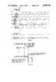
- FIGS. 6(A) through 6(F)are waveforms that generally illustrate the operation of the circuits of FIG. 5;
- FIGS. 7(A) through 7(H)are waveforms that show a specific example of the operation of the circuits of FIG. 5;
- FIGS. 8(A) and 8(B)are tables that further illustrate that example of the operation of the circuits of FIG. 5.
- the receiverhas provisions for connection to an appropriate antenna 11.
- the signals from the antenna 11are simultaneously applied to two portions of a radio frequency section, one portion 13 for reducing the frequency bands of the several L1 signals present, and a portion 15 for reducing the frequency bands of the several L2 signals present.
- An output 19 of the L2 radio frequency section 15is, in this specific example, a 1f 0 signal with practically all modulated information removed, so has a narrow bandwidth.
- Both of the portions 13 and 15 of the radio frequency sectionreceive local oscillator signals from a common timing circuit 21.
- Each of the L1 intermediate frequency signal in line 17 and the L2 intermediate frequency signal in line 19is applied to each of a plurality of individual digital processing channels 23, 25, and 27. It is necessary to simultaneously process signals from several satellites, and depending upon the particular information to be derived, usually needs to monitor signals from four or more satellites. It is preferable, however, that a number of digital processing channels be provided that is equal to the maximum number of satellites whose signals may be simultaneously monitored and processed by the receiver when applied to its intended use. Control and processing circuits 29 control the operation of the digital processing channels 23-27 and receive the measured phase, frequency, and code phase outputs of each channel for calculating the ultimate quantity of distance, velocity or the like depending upon the receiver's intended applications.
- the desired measurement and calculationsmay be made without the L2 portion 15 of the radio frequency section, thereby eliminating the reduced frequency L2 carrier signal in the line 19 from all of the digital processing channels 23-27.
- the primary purpose of using the L2 carrier signalis to provide a reference for eliminating from the L1 carrier signal measured quantities the effect of the ionosphere.
- a preferred type of antenna 11is in the form of an omni-directional one and is generally a microstrip patch. Signals received from the satellites are right circular polarized, so the optimal antenna efficiently reconstructs a signal of that polarization while rejecting the cross-polarization that results from reflected signals.
- the L1 radio frequency section portion 13includes two down-converters.
- a bandpass filter 31receives the signals from the antenna 11 and is centered to pass the L1 carrier frequency of 1540f 0 .
- the bandwidth of the filter 31is made to be greater than the 2f 0 MHz bandwidth of the C/A code in the L1 signal, typically a bandwidth of 35 MHz.
- the filter 31strongly suppresses the L2 and other signals outside its bandpass, including a band of image frequencies near the L2 band.
- the filter outputis applied to a radio frequency amplifier 33 that is selected to have high gain but yet low noise, one made of gallium arsenide components being found preferable.
- the output of that amplifieris applied to a first mixer 35 which also receives a local oscillator frequency of 1372f 0 in a line 37.
- the mixer 35is preferably a commercially available double-balanced mixer.
- the signal output of the mixer 35is then applied to another bandpass filter 39.
- the filter 39has a center of its bandpass at 168f 0 , the difference between the two frequencies applied to the mixer 35. The sum of those frequencies, which is also included in the output of the mixer 35, is rejected by the filter 39.
- the bandwidth of the filter 39is approximately 2.2 MHz, slightly greater than that of the spectrum of the C/A-code.
- the filter 39is preferably a surface acoustic wave (SAW) type.
- the band limited signal output of the filter 39is then amplified by a monolithic silicon amplifier 41. That amplifier's output is then applied to a second mixer 43 which receives a local oscillator signal having a frequency of 171.5f 0 from the timing circuits 21 in a line 45.
- the difference frequency of about 3.5f 0 output of the mixer 41is then amplified by a commercially available high gain amplifier 47 operating in a non-linear, saturated region.
- the amplifier 47limits the level of the signal to components to which its output is connected, in order to avoid overdriving them. Only the phase of the signal must be preserved by the components in the radio frequency section, so clipping of the signal's amplitude is of no concern.
- the output of the amplifier 47is applied to a comparator 49 which translates that amplifier output to digital logic levels in line 17 for use by the digital processing channels 23-27.
- the L2 radio frequency section portion 15connects the signal from the antenna 11 to a bandpass filter 51 having a center bandpass frequency of 1200f 0 , the L2 carrier frequency.
- An amplifier 53applies an amplified version of that band limited signal to a first mixer 55.
- the mixer 55receives the same local oscillator signal from line 37 that does the first mixer 35 of the L1 radio frequency section portion 13, thereby reducing the complexity of the circuit that would result if a different local oscillator frequencies were used.
- the frequency of that local oscillatornamely 1372f 0 , is chosen to be intermediate of the carrier frequencies of the L1 and L2 signals.
- An output of the first mixer 55is applied to a bandpass filter centered at 172f 0 , which passes the difference frequency output of the mixer 55.
- the filter signalis then amplified by amplifier 57 which passes the difference frequency output of the mixer 55, that frequency being 172f 0 .
- the output of the amplifier 57is applied to an autocorrelator, made up of coupler 59 and a mixer 61.
- the mixer 61receives as its radio frequency and local oscillator signals the same L2 signal from the output of the amplifier 57.
- the resultis an output signal, then applied to a bandpass filter 63, that has doubled in frequency, namely to 344f 0 , but which has its spread spectrum collapsed into a narrow bandwidth signal.
- the autocorrelationresults in all of the modulating information in the satellite being eliminated from the signal so that L2 carrier frequency and relative phase can be measured.
- the modulating informationis the P-code pseudo-random function and data that is to be militarily classified, and the autocorrelation simply eliminates the effect of this unknown modulating signal from the signal being examined by the receiver.
- An output of the bandpass filter 63is applied to a second down-converter mixer 65 that also receives a local oscillator signal in a line 67 that is 343f 0 . Therefore, an output of the mixer 65 is a difference signal of 1f 0 . This difference signal is applied to a bandpass filter 62 which has a center frequency of 1f 0 . The filtered signal is amplified by amplifier 64 and converted to a digital signal in a comparator 66 which translates the amplifier output to digital levels for use by the amplifier processing channels 23-27.
- the clock and timing circuits 21 of the receiver of FIG. 1are shown in more detail in FIG. 2. All of the local oscillator, clock signals and timing signals of the receiver are developed from the output of a very stable oscillator 71.
- the oscillator 71preferably includes an oven temperature controlled crystal so that the output frequency is very precise and stable. In the particular receiver example being described herein, that output is chosen to have a frequency of 20f 0 , which is connected directly to one of the timing circuit output lines 73 for utilization by the digital circuits.
- the output of the oscillator 71is passed through a dividing circuit 75 and then to a phase locked loop including a phase detector 77, a loop filter 78, a voltage controlled oscillator 79, and dividing circuits 81, 83 and 85, all in a series loop.
- the circuit 75divides the oscillator 71 output by 40 and the voltage controlled oscillator has a frequency output of 1372f 0 when zero voltage is applied to the loop filter 78.
- the 1372f 0 outputis that which is applied by line 37 to mixers 35 and 55 of the receiver of FIG. 1.
- That signalis then divided by 4 by the circuit 81, resulting in producing the local oscillator signal 343f 0 in line 67 that is applied to the mixer 65 of the receiver of FIG. 1.
- the circuit 83divides that frequency by 2, resulting in the local oscillator frequency 171.5f 0 in a line 45 that is applied to the mixer 43 of the receiver of FIG. 1.
- the circuit 85divides that signal by 343 before applying it to the phase detector 77.
- a divide-by-nine circuit 87produces a 19.05f 0 signal in a line 89
- a divide-by-five circuit 91produces a 34.3f 0 clock signal in a line 93, both of the circuits 87 and 91 receiving the 171.5f 0 signal from the line 45.
- a divide-by-ten circuit 95is connected to the 20f 0 clock signal in line 73 in order to generate in line 97 a 2f 0 clock.
- a divide-by-20 circuit 99produces a 1f 0 clock in a line 101. That clock is further divided by 1023 by a dividing circuit 103, thereby producing in a line 105 a clock signal having a period of 1 millisecond.
- each of the channel processors 23-27is given. This is the portion of each of those circuits that processes the reduced frequency L1 signal in the line 17 for only one of several satellites whose signals are simultaneously being received and processed.
- a primary purpose of these circuitsis to provide signals from which the ultimate quantities of distance, position, velocity, time, and the like may be calculated. This includes signals proportional to the relative phase of the L1 carrier and to the C/A code.
- the incoming signal in the line 17is applied to a pair of digital mixers 111 and 113.
- the L1 signalis demodulated by a locally generated estimate of the C/A-code in line 115 for the one satellite whose signals are being processed by the circuit of FIG. 3.
- An output of the digital mixer 111 in line 117is then the reduced frequency L1 signal modulated only with the navigation (NAV) data and noise.
- a demodulating signal applied to the digital mixer 113 in a line 119is a locally generated estimate of the reduced frequency L1 carrier component of the signal in line 17 for this particular satellite.
- An output of the mixer 113, in a line 121is the C/A-code modulated with NAV data of the one satellite, plus noise.
- a phase locked loop circuit 123has as a principal purpose to lock onto the L1 carrier for a single satellite that has been separated from all of the satellite L1 signals into line 117.
- Each satellite's L1 signalwill have a frequency that varies within a small range of frequencies about 1540f 0 , depending upon the velocity of the satellite relative to the receiver, in accordance with the Doppler effect. Since the C/A code is unique for each satellite, the circuit 123 locks upon the L1 frequency of the satellite whose C/A code is being generated by a receiver circuit 127.
- One output of the phase lock loop 123is a replica of that L1 carrier signal, in the line 119.
- a second principal portion of the circuit of FIG. 3is an early-late tracking loop 125 that has as a purpose the generation of an estimate of the C/A-code in a line 115 that has the same information content and is of the same phase as that in the L1 signal being received for the one satellite.
- the early-late tracking loop 125is of a type that is well-known in spread spectrum satellite communications technology.
- the known C/A-code for the one satelliteis generated by the circuit 127.
- the C/A-code generated in each of the digital processing channels 23-27will be different, and unique to each satellite being used.
- the known pseudo-random bit pattern, repeating every one millisecond,is known but its relative phase is not. Therefore, the purpose of the circuit 125 is to shift the phase of the locally generated C/A-code in order to produce in the line 115 a code that is in synchronism with the L1 signal that is modulated by that unique C/A-code.
- the early-late tracking loop 125also has a purpose of measuring that relative phase shift and producing, for use by the control and processing circuits 29, a signal in lines 129 that is proportional to that phase shift. This quantity is important information that is used by the processor in order to calculate the ultimate quantities of position, velocity, and the like.
- the loop 125includes a phase shifting circuit as part of circuit 127 that forms in a line 133 an advanced phase version of the C/A-code and forms in the line 135 a phase delayed version of that code.
- These signalsare applied, respectively, to digital mixers 137 and 139 for correllating with the signal in the line 121.
- the outputs of those mixersare applied to an up/down counter 141 which has as an output 143 a signal proportional to an error resulting when the advanced and delayed C/A-code in lines 133 and 135, respectively, are not equally displaced in phase on either side of the C/A-code in line 121 that is contained in the signal being processed.
- phase lock loop 123is well known in satellite communication systems for locking onto a carrier signal.
- This carrier signalis applied to a phase detector 147 which produces as an output in a line 149 any difference in the phase of the signal in line 117 and that in a line 119.
- An up/down counter 151receives the signal in line 149 and serves to integrate it over the period of the C/A code.
- a line 131carries a signal at the occurrence of a particular: state of the locally generated nominal C/A code. This will occur nominally at a one millisecond rate, modified by any phase shift caused by any Doppler effect and local oscillator offset.
- the integration of the signal in line 149 in synchronism with data transitionsassures that no data transition occurs during the integration period.
- An output of the counter 151is proportional to the phase of the L1 carrier, and that is applied through a loop filter and processor 153 to a numerically controlled oscillator ("NCO") 155.
- a signal in line 157is proportional to the phase error between the L1 carrier and the locally generated estimate of the carrier. It is available for use by the control and processing circuits 29.
- the NCO 155has an output in lines 159 from which the relative phase of the L1 carrier may be measured. That signal, and a shift pulse signal in a line 161 from the NCO 155, are applied to phase measuring circuits 163. Circuits 163 are responsive to various clocks and a control signal in lines 165. A resulting signal in lines 167 is proportional to the phase of the L1 carrier from the one satellite whose signals are being processed by the one processing channel, relative to the phase of L1 carriers from other satellites that are being processed in other of the digital processing channels 23-27.
- the frequency of the L1 carrier generated by each satelliteis very stable, the signal received will be affected by any relative movement between the satellite and the receiver, according to the Doppler effect.
- the frequency and relative phase of the L1 carrier from a particular satellitewill vary as that satellite moves across the portion of space that is visible to the receiver.
- the signal in line 117is applied to a mixer 171 that receives as a demodulating signal in a line 173 the estimate of the L1 carrier in line 119 after having been shifted ninety degrees in phase by a circuit 175.
- the resulting demodulated signalis applied to an up/down counter 177 whose output in circuits 179 is the desired navigational data of the one satellite.
- each of the digital processing channels 23-27may contain processing circuitry illustrated in FIG. 4.
- a phase locked loop 181is provided that is of the same basic design as the loop 123 of FIG. 3. It also has the same general function, except that it is operating with respect to the L2 carrier instead of the L1 carrier. Since the autocorrelated (squared) L2 carrier contains no navigational data, the circuit of FIG. 4 does not include provisions for dealing with navigational data. Similarly, squaring the L2 signal removes the pseudo-random signal. As a result, there is no local generation and relative phase shift of such a modulating signal in the circuit of FIG. 4 as there is with the C/A-code in the circuit of FIG. 3.
- the control and processing circuits 29calculate the Doppler frequency shift for that satellite from its L1 signal, scale that frequency shift for the different L2 frequency, multiply by two, add it to the nominal L2 frequency and then start the numerically controlled oscillator of the loop 181 at that calculated L2 frequency. Once locked on that frequency, the loop 181 will follow its frequency changes as the satellite moves across the sky.
- phase measuring circuits 163of FIG. 3. Details of the phase measuring circuits 163 are given in FIG. 5, as well as their interaction with the numerically controlled oscillator 155.
- the phase measuring circuits 163include a base phase measuring circuit 201 and an incremental phase measuring circuit 203.
- An output 238 of the circuit 203is divided by a programmed dividing circuit 210.
- the divided output 207is then combined with the base phase output 205 of the circuit 201 by an adder 209 in order to provide a single relative phase value in lines 167.
- the dividing and adding functions of elements 209 and 210can alternately be performed by software in the processing circuits 29.
- a principal component of the NCO 155is a counter 211 whose output is a plurality of bits in line 159. The most significant bit of the counter output is carried by the line 119. It is desired that the frequency of the signal in the line 119 be 3.5f 0 , the nominal intermediate frequency of the L1 carrier that is applied to the digital processing circuitry without any effect of a Doppler frequency shift.
- the counter 211since the L1 carrier frequency will change somewhat because of the Doppler effect, the counter 211 must be variable enough to be able to track and lock on such frequency variations.
- the counter 211 in this specific exampleis chosen to normally count to ten before automatically repeating, thereby normally producing a signal in the line 119 that is 1/10th of the frequency of the clock signal driving the counter 211.
- the line 161carries a control signal to the counter 211. When the counter receives a pulse in the line 161, its next cycle counts only to 9 instead of 10, while subsequent cycles count to ten until another pulse is received in the line 161.
- the counter shift pulses in the line 161are developed from a state machine 213 that includes an adder 215 and a plurality of paralleled flip-flops 217.
- the output of the flip-flops 217become one of the two inputs of the adder 215, the other input of the adder coming from a control register 219 that is loaded with a word that represents the desired frequency of the NCO 155 output.
- the most significant bit of the word stored in the flip-flops 217is passed by line 221 to an edge detecting circuit 223 that outputs a pulse in the line 161 each time the waveform in the line 221 transitions from a zero to a one.
- FIG. 6(A)shows a waveform in NCO line 221 having a nominal frequency of 0.7f 0 , a result of the circuit 213 being driven by a clock of 2f 0 . That results in a shift pulse in line 161 at each rising edge of that signal, as shown in FIG. 6(B).
- FIG. 6(D)illustrates that the output of the counter 211 in line 119 will normally have a period of ten cycles of its 34.3f 0 clock except immediately after receiving a shift pulse.
- 6(D)illustrates the difference in the shape of the waveform in line 119 when the counter 211 cycles in nine counts in response to a shift pulse, as shown in a solid line, as opposed to when it is allowed to go its full ten counts, as shown in a dashed line.
- the counter 211needs to divide its clock signal of 34.3f 0 by 9.8 in order to produce a 3.5f 0 signal in the line 119 that will keep the phase lock loop 123 of FIG. 3 locked onto the reduced frequency L1 signal, without any Doppler frequency shift. This is accomplished changing the modulo of the divide of the counter 211 to nine once every five cycles of the in-phase clock of line 119, thereby dividing the 34.3f 0 clock by an average of 9.8 over five cycles.
- a measure of the phase of the L1 carrier signal being processed by the circuit of FIG. 5 in a particular processing channel, relative to the phases of the signals being processed by the other channels,is obtained by latching the output 159 of the NCO counter 211 in each channel at the same time.
- a latch 227is provided for this purpose and is latched on the declining edge of the one millisecond clock.
- FIG. 6(C)shows an example of the one millisecond clock and its decreasing edge 229.
- FIG. 6(D)represents the output of the most significant bit of the counter 211 as a function of time, a reading of all bits at the time indicated at 229 giving a measure of the relative phase of the L1 signal being processed by this channel.
- FIG. 6(C)shows an example of the one millisecond clock and its decreasing edge 229.
- FIG. 6(D)represents the output of the most significant bit of the counter 211 as a function of time, a reading of all bits at the time indicated at 229 giving a measure of the relative phase of the L1
- FIG. 6(E)shows an example of the in-phase clock of another channel that is processing a L1 carrier frequency from a different satellite, its relative phase at the time indicated at 229 being something different, its NCO counter having a different output that is latched.
- FIG. 6(F)shows the in-phase clock of a third digital processing channel where its output indicates another relative phase.
- phase measuring circuits qf FIG. 5refine the relative phase stored in the latch 227 by use of circuits 203.
- the incremental phase measurement circuits 203monitor the phase of a number of cycles of the L1 signal carrier replica in the line 119 that occur in a fixed time after the instant 229 when a base phase is measured by storing the count of the counter 211 into the latch 227.
- This fine phase measurementis conveniently accomplished in the circuits 203 shown in FIG. 5, wherein an average number of shift pulses occurring in the line 161 is measured during a specified number "A" of 3.43f 0 clock cycles after the base phase latching instant 229.
- This average number of shift pulses over many such clock cyclesperhaps hundreds, provides a high resolution incremental phase measurement that, when arithmetically combined with the base phase measurement stored in the latch 227, gives in lines 167 a relative phase measurement for this channel that is extremely accurate and has a very high degree of resolution.
- the circuit 203 of FIG. 5will now be explained with respect to a specific example of its operation given by FIGS. 7 and 8.
- the 34.3f 0 clock in line 93is divided by 10 by a circuit 232.
- the resulting 3.43f 0 accumulator clock (FIG. 7(F)) in line 233drives timing logic circuits 236 which develop timing signals for a counter 231 and an accumulator 237. Operation of the circuit is keyed to the decreasing edge of the 1 msec. clock, such as the edge 229 of FIGS. 6 and 7.
- the base phaseis latched in the latch 227 at the same time as the shift accumulator 237 is enabled.
- a clear/reset signal(FIG.
- a line 235carries an enable signal (FIG. 7(H)) to the accumulator 237.
- the timing logic circuits 236cause the enable signal to begin at the time 229 and continue for "A" number of cycles of the accumulator clock in the line 233, this number being four in the example being described, for simplicity, but will typically be 100 or more in practice.
- the constant "A”is set by a hardware connection or software control through a line 165.
- the number of shift pulses in the line 161is counted by the counter 231 beginning after the counter is reset at time 229.
- the counter 231continues to count shift pulses until again reset at the beginning of another cycle.
- the accumulator 237is clocked by the accumulator clock (FIG. 7(F)) in the line 233.
- the accumulator 237begins at zero at time 229 when reset. At a leading edge of the first cycle of the accumulator clock occuring after time 229, it stores the count of the counter 231. At the next clock leading edge, the accumulator 237 adds the value of the counter at that instant to what is already in the accumulator.
- FIGS. 7 and 8A specific simplified example of the operation of the circuits of FIG. 5 is given in FIGS. 7 and 8 for two receiver channels 1 and 2. That is, the digital processing circuits of FIG. 5 are duplicated in each of the channels 1 and 2 (blocks 23 and 25 of FIG. 1, respectively).
- FIG. 7(B)shows the L1 signal carrier in line 119 of the channel 1 processing circuits
- FIG. 7(D)the same the channel 2 processing circuits, each channel being locked on a signal from a different satellite.
- FIG. 7(C)shows an example of two shift pulses being received in the line 161 of the channel 1 processing circuits during "A" number of accumulator clock cycles
- FIG. 7(E)shows a single shift pulse being received during that period by the channel 2 processing circuits.
- the Table of FIG. 8(A)illustrates what is being accumulated in each of the two example channels.
- the first sample period illustrated in FIG. 7(F)nothing is stored in the accumulator 237 for either channel since no shift pulse occurs during that period in either channel. Their respective counters 231 are thus not incremented during that period.
- a shift pulse(FIG. 7(C)) is received by the counter 231 in channel 1, and at the end of that period is added into the accumulator 237, as indicated by the Table of FIG. 8(A).
- sample period number 3a shift pulse is received by the circuits of channel 2, but none in channel 1, so the counter 231 state in each channel is 1 and this is added to their respective accumulators 237.
- a shift pulseoccurs in channel 1, thus incrementing its counter 231 to the value of 2, which number is added to the channel 1 accumulator 237 at the end of the fourth sample period. Since no shift pulse occurs during the fourth sample period in channel 2, its counter 231 retains the count of 1, which is added to its accumulator 237 during that sample period.
- the accumulator enable signal(FIG. 7(H)) goes low to disable any further operation of the accumulators 237 in all channels, the accumulator of channel 1 contains the number 4, and that of channel 2 the number 2.
- Those accumulated shift pulse numbersare then divided by the number of sample periods, in circuits 210 of each channel, to obtain an average. That average for channel 1 is 1.0, and for channel 2 is 0.5. As shown in the Table of FIG. 8(B), those averages are added, by circuits 209 in each channel, to the base phase measurements in those channels, the result being the desired high resolution relative phase measurement.
- the base phase measurement of this example for channel 1is the phase of the signal of FIG. 7(B) at time 229, shown to be 4.
- the base phase in channel 2is given in FIG. 7(D) at time 229, being 5.
- the phases shown on the signals of FIGS. 7(B) and 7(D)are in hexadecimal form.
- the accumulators 237can be very large. Therefore, it is usually preferred to select an up/down counter for the shift counter 231 in each channel.
- the shift pulsescause it to count up and some periodically occuring clock signal applied to the counters of each receiver channel cause the counter to count down. That limits the size of the numbers that need to be accumulated, but does so similarly in the processing circuits of each channel, so the relative phases being measured do not change.
- such a down counting clockcan be obtained by dividing the accumulator clock in line 233 by five.
- FIG. 5The circuits of FIG. 5 have been described in detail for the L1 signal processing. Similar circuits operating in a similar way are provided as part of FIG. 4 for processing the L2 signal, with an adjustment of clock frequencies and shift rates being made because of its different carrier frequency.
Landscapes
- Engineering & Computer Science (AREA)
- Radar, Positioning & Navigation (AREA)
- Remote Sensing (AREA)
- Computer Networks & Wireless Communication (AREA)
- Physics & Mathematics (AREA)
- General Physics & Mathematics (AREA)
- Signal Processing (AREA)
- Position Fixing By Use Of Radio Waves (AREA)
- Circuits Of Receivers In General (AREA)
Abstract
Description
Claims (15)
Priority Applications (7)
| Application Number | Priority Date | Filing Date | Title |
|---|---|---|---|
| US07/219,353US4928106A (en) | 1988-07-14 | 1988-07-14 | Global positioning system receiver with improved radio frequency and digital processing |
| JP1176992AJP2919490B2 (en) | 1988-07-14 | 1989-07-07 | Global positioning system with improved radio frequency and digital processing. |
| DE68923916TDE68923916D1 (en) | 1988-07-14 | 1989-07-10 | GPS locating receiver with radio frequency section and data processing section. |
| AT89306962TATE126895T1 (en) | 1988-07-14 | 1989-07-10 | GPS-TYPE LOCATION RECEIVER WITH RADIO FREQUENCY PART AND DATA PROCESSING PART. |
| EP89306962AEP0351156B1 (en) | 1988-07-14 | 1989-07-10 | Global positioning system receiver with radio frequency and digital processing sections |
| CA000605519ACA1334110C (en) | 1988-07-14 | 1989-07-13 | Global positioning system receiver with improved radio frequency and digital processing |
| AU38163/89AAU622688B2 (en) | 1988-07-14 | 1989-07-14 | Global positioning system receiver with improved radio frequency and digital processing |
Applications Claiming Priority (1)
| Application Number | Priority Date | Filing Date | Title |
|---|---|---|---|
| US07/219,353US4928106A (en) | 1988-07-14 | 1988-07-14 | Global positioning system receiver with improved radio frequency and digital processing |
Publications (1)
| Publication Number | Publication Date |
|---|---|
| US4928106Atrue US4928106A (en) | 1990-05-22 |
Family
ID=22818943
Family Applications (1)
| Application Number | Title | Priority Date | Filing Date |
|---|---|---|---|
| US07/219,353Expired - LifetimeUS4928106A (en) | 1988-07-14 | 1988-07-14 | Global positioning system receiver with improved radio frequency and digital processing |
Country Status (7)
| Country | Link |
|---|---|
| US (1) | US4928106A (en) |
| EP (1) | EP0351156B1 (en) |
| JP (1) | JP2919490B2 (en) |
| AT (1) | ATE126895T1 (en) |
| AU (1) | AU622688B2 (en) |
| CA (1) | CA1334110C (en) |
| DE (1) | DE68923916D1 (en) |
Cited By (90)
| Publication number | Priority date | Publication date | Assignee | Title |
|---|---|---|---|---|
| US5134407A (en)* | 1991-04-10 | 1992-07-28 | Ashtech Telesis, Inc. | Global positioning system receiver digital processing technique |
| US5202694A (en)* | 1991-09-10 | 1993-04-13 | Trimble Navigation | P-code generation |
| US5225842A (en)* | 1991-05-09 | 1993-07-06 | Navsys Corporation | Vehicle tracking system employing global positioning system (gps) satellites |
| US5245628A (en)* | 1991-03-29 | 1993-09-14 | Texas Instruments Incorporated | Enhanced l1/l2 code channel for global positioning system receivers |
| US5343209A (en)* | 1992-05-07 | 1994-08-30 | Sennott James W | Navigation receiver with coupled signal-tracking channels |
| US5347546A (en)* | 1992-04-28 | 1994-09-13 | Ashtech, Inc. | Method and apparatus for prefiltering a global positioning system receiver |
| US5379224A (en)* | 1991-11-29 | 1995-01-03 | Navsys Corporation | GPS tracking system |
| US5465289A (en)* | 1993-03-05 | 1995-11-07 | E-Systems, Inc. | Cellular based traffic sensor system |
| US5502641A (en)* | 1993-12-27 | 1996-03-26 | Sokkia Co., Ltd. | Relative GPS method and apparatus that is able to correct for momemtary signal interruption |
| US5510798A (en)* | 1993-04-02 | 1996-04-23 | Bauer; William D. | Multiple-accuracy GPS system |
| US5535237A (en)* | 1991-02-28 | 1996-07-09 | Texas Instruments Incorporated | Method and system for a multi channel and search global position system signal processor |
| US5541606A (en)* | 1995-02-02 | 1996-07-30 | Trimble Navigation Limited | W-code enhanced cross correlation satellite positioning system receiver |
| US5548293A (en)* | 1993-03-24 | 1996-08-20 | Leland Stanford Junior University | System and method for generating attitude determinations using GPS |
| US5576715A (en)* | 1994-03-07 | 1996-11-19 | Leica, Inc. | Method and apparatus for digital processing in a global positioning system receiver |
| US5579014A (en)* | 1995-01-20 | 1996-11-26 | General Electric Company | Parallel correlator for global positioning system receiver |
| US5583513A (en)* | 1993-03-24 | 1996-12-10 | Board Of Trustees Of The Leland Stanford Junior University | System and method for generating precise code based and carrier phase position determinations |
| US5621416A (en)* | 1995-02-02 | 1997-04-15 | Trimble Navigation Limited | Optimized processing of signals for enhanced cross-correlation in a satellite positioning system receiver |
| US5623414A (en)* | 1995-01-24 | 1997-04-22 | Massachusetts Inst Technology | Clock-aided satellite navigation receiver system for enhanced position estimation and integrity monitoring |
| US5684476A (en)* | 1993-12-30 | 1997-11-04 | Concord, Inc. | Field navigation system |
| US5686925A (en)* | 1994-06-30 | 1997-11-11 | Matsushita Electric Industrial Co., Ltd. | System for obtaining a velocity of a moving object from a speed sensor with an improved adjustment of a speed conversion coefficient |
| US5689271A (en)* | 1996-05-03 | 1997-11-18 | Trimble Navigation Limited | Method and apparatus for civilian receiver operation with P(Y) code in satellite positioning system receiver |
| US5703597A (en)* | 1995-12-22 | 1997-12-30 | Alliedsignal, Inc. | Adaptive carrier phase lock loop in a GPS receiver |
| US5717403A (en)* | 1995-09-06 | 1998-02-10 | Litton Consulting Group, Inc. | Method and appartus for accurate frequency synthesis using global positioning system timing information |
| US5736961A (en)* | 1995-10-06 | 1998-04-07 | Novatel, Inc. | Dual Frequency global positioning system |
| US5859878A (en)* | 1995-08-31 | 1999-01-12 | Northrop Grumman Corporation | Common receive module for a programmable digital radio |
| US5897605A (en)* | 1996-03-15 | 1999-04-27 | Sirf Technology, Inc. | Spread spectrum receiver with fast signal reacquisition |
| US5901171A (en)* | 1996-03-15 | 1999-05-04 | Sirf Technology, Inc. | Triple multiplexing spread spectrum receiver |
| US5931889A (en)* | 1995-01-24 | 1999-08-03 | Massachusetts Institute Of Technology | Clock-aided satellite navigation receiver system for monitoring the integrity of satellite signals |
| US5953367A (en)* | 1995-08-09 | 1999-09-14 | Magellan Corporation | Spread spectrum receiver using a pseudo-random noise code for ranging applications in a way that reduces errors when a multipath signal is present |
| US6018704A (en)* | 1996-04-25 | 2000-01-25 | Sirf Tech Inc | GPS receiver |
| US6031487A (en)* | 1998-03-25 | 2000-02-29 | Rockwell Collins, Inc. | GPS pseudolite and receiver system using high anti-jam pseudolite signal structure |
| US6041280A (en)* | 1996-03-15 | 2000-03-21 | Sirf Technology, Inc. | GPS car navigation system |
| US6047017A (en)* | 1996-04-25 | 2000-04-04 | Cahn; Charles R. | Spread spectrum receiver with multi-path cancellation |
| US6078283A (en)* | 1997-10-31 | 2000-06-20 | Input/Output, Inc. | Remote seismic data acquisition unit with common radio and GPS antenna |
| US6125135A (en)* | 1998-11-25 | 2000-09-26 | Navcom Technology, Inc. | System and method for demodulating global positioning system signals |
| US6125325A (en)* | 1996-04-25 | 2000-09-26 | Sirf Technology, Inc. | GPS receiver with cross-track hold |
| US6195328B1 (en) | 1998-04-15 | 2001-02-27 | The United States Of America As Represented By The Secretary Of The Air Force | Block adjustment of synchronizing signal for phase-coded signal tracking |
| US6198765B1 (en) | 1996-04-25 | 2001-03-06 | Sirf Technologies, Inc. | Spread spectrum receiver with multi-path correction |
| US20010002203A1 (en)* | 1996-04-25 | 2001-05-31 | Cahn Charles R. | Spread spectrum receiver with multi-path correction |
| US6249542B1 (en) | 1997-03-28 | 2001-06-19 | Sirf Technology, Inc. | Multipath processing for GPS receivers |
| US6282231B1 (en) | 1999-12-14 | 2001-08-28 | Sirf Technology, Inc. | Strong signal cancellation to enhance processing of weak spread spectrum signal |
| US6369752B1 (en)* | 1999-05-28 | 2002-04-09 | Rockwell Collins, Inc. | Direct acquistion of very large PN sequences in GPS systems |
| US6393046B1 (en) | 1996-04-25 | 2002-05-21 | Sirf Technology, Inc. | Spread spectrum receiver with multi-bit correlator |
| US6493378B1 (en) | 1998-01-06 | 2002-12-10 | Topcon Gps Llc | Methods and apparatuses for reducing multipath errors in the demodulation of pseudo-random coded signals |
| DE19742424C2 (en)* | 1996-09-27 | 2003-10-16 | Nec Compound Semiconductor | Doppelsuperheterodyn receiver circuit |
| US6768767B1 (en)* | 1997-11-13 | 2004-07-27 | Sokkia Company Limited | GPS receiver capable of receiving C/A and P codes on multiple channels |
| US20050162307A1 (en)* | 2004-01-22 | 2005-07-28 | Denso Corporation | Satellite-positioning signal receiving device |
| US20050242990A1 (en)* | 2004-04-29 | 2005-11-03 | Integrinautics Corporation | Signal path system and method for a ranging signal receiver |
| US20060028377A1 (en)* | 2004-08-05 | 2006-02-09 | Charles Abraham | Method and apparatus for adjusting a measurement cycle in a satellite positioning system signal receiver |
| USH2155H1 (en) | 2002-01-28 | 2006-05-02 | The United States Of America As Represented By The Secretary Of The Air Force | Downconvert and average identification of biphase coded signal carrier |
| US20060217885A1 (en)* | 2005-03-24 | 2006-09-28 | Mark Crady | User location driven identification of service vehicles |
| US20070008218A1 (en)* | 2004-02-10 | 2007-01-11 | Nicolas Vantalon | Tracker architecture for GPS systems |
| US20070257831A1 (en)* | 2006-04-28 | 2007-11-08 | Loctronix Corporation | System and method for positioning in configured environments |
| US7715461B2 (en) | 1996-05-28 | 2010-05-11 | Qualcomm, Incorporated | High data rate CDMA wireless communication system using variable sized channel codes |
| WO2011020399A1 (en)* | 2009-08-18 | 2011-02-24 | 上海华测导航技术有限公司 | Radio frequency circuit structure for realizing function of converting dual-frequency global positioning system (gps) satellite signal into baseband signal |
| CN102062863A (en)* | 2010-11-17 | 2011-05-18 | 东莞市泰斗微电子科技有限公司 | Satellite navigation RF (Radio-Frequency) module |
| US8369967B2 (en) | 1999-02-01 | 2013-02-05 | Hoffberg Steven M | Alarm system controller and a method for controlling an alarm system |
| US8750156B1 (en) | 2013-03-15 | 2014-06-10 | DGS Global Systems, Inc. | Systems, methods, and devices for electronic spectrum management for identifying open space |
| US8780968B1 (en) | 2013-03-15 | 2014-07-15 | DGS Global Systems, Inc. | Systems, methods, and devices for electronic spectrum management |
| US8787836B1 (en) | 2013-03-15 | 2014-07-22 | DGS Global Systems, Inc. | Systems, methods, and devices having databases and automated reports for electronic spectrum management |
| US8798548B1 (en) | 2013-03-15 | 2014-08-05 | DGS Global Systems, Inc. | Systems, methods, and devices having databases for electronic spectrum management |
| US8805292B1 (en) | 2013-03-15 | 2014-08-12 | DGS Global Systems, Inc. | Systems, methods, and devices for electronic spectrum management for identifying signal-emitting devices |
| US8892495B2 (en) | 1991-12-23 | 2014-11-18 | Blanding Hovenweep, Llc | Adaptive pattern recognition based controller apparatus and method and human-interface therefore |
| US9151633B2 (en) | 1998-01-27 | 2015-10-06 | Steven M. Hoffberg | Mobile communication device for delivering targeted advertisements |
| US20160245923A1 (en)* | 2008-12-11 | 2016-08-25 | Hemisphere Gnss Inc. | Global navigation satellite system superband processing device and method |
| US9455762B2 (en) | 2006-04-28 | 2016-09-27 | Telecommunication Systems, Inc. | System and method for positioning using hybrid spectral compression and cross correlation signal processing |
| US9906191B1 (en) | 2010-08-02 | 2018-02-27 | Hypres, Inc. | Superconducting multi-bit digital mixer |
| US10122479B2 (en) | 2017-01-23 | 2018-11-06 | DGS Global Systems, Inc. | Systems, methods, and devices for automatic signal detection with temporal feature extraction within a spectrum |
| US10219163B2 (en) | 2013-03-15 | 2019-02-26 | DGS Global Systems, Inc. | Systems, methods, and devices for electronic spectrum management |
| US10231206B2 (en) | 2013-03-15 | 2019-03-12 | DGS Global Systems, Inc. | Systems, methods, and devices for electronic spectrum management for identifying signal-emitting devices |
| US10237770B2 (en) | 2013-03-15 | 2019-03-19 | DGS Global Systems, Inc. | Systems, methods, and devices having databases and automated reports for electronic spectrum management |
| US10244504B2 (en) | 2013-03-15 | 2019-03-26 | DGS Global Systems, Inc. | Systems, methods, and devices for geolocation with deployable large scale arrays |
| US10257729B2 (en) | 2013-03-15 | 2019-04-09 | DGS Global Systems, Inc. | Systems, methods, and devices having databases for electronic spectrum management |
| US10257727B2 (en) | 2013-03-15 | 2019-04-09 | DGS Global Systems, Inc. | Systems methods, and devices having databases and automated reports for electronic spectrum management |
| US10257728B2 (en) | 2013-03-15 | 2019-04-09 | DGS Global Systems, Inc. | Systems, methods, and devices for electronic spectrum management |
| US10271233B2 (en) | 2013-03-15 | 2019-04-23 | DGS Global Systems, Inc. | Systems, methods, and devices for automatic signal detection with temporal feature extraction within a spectrum |
| US10299149B2 (en) | 2013-03-15 | 2019-05-21 | DGS Global Systems, Inc. | Systems, methods, and devices for electronic spectrum management |
| US10361802B1 (en) | 1999-02-01 | 2019-07-23 | Blanding Hovenweep, Llc | Adaptive pattern recognition based control system and method |
| US10459020B2 (en) | 2017-01-23 | 2019-10-29 | DGS Global Systems, Inc. | Systems, methods, and devices for automatic signal detection based on power distribution by frequency over time within a spectrum |
| US10498951B2 (en) | 2017-01-23 | 2019-12-03 | Digital Global Systems, Inc. | Systems, methods, and devices for unmanned vehicle detection |
| US10529241B2 (en) | 2017-01-23 | 2020-01-07 | Digital Global Systems, Inc. | Unmanned vehicle recognition and threat management |
| US10644815B2 (en) | 2017-01-23 | 2020-05-05 | Digital Global Systems, Inc. | Systems, methods, and devices for automatic signal detection based on power distribution by frequency over time within an electromagnetic spectrum |
| US10943461B2 (en) | 2018-08-24 | 2021-03-09 | Digital Global Systems, Inc. | Systems, methods, and devices for automatic signal detection based on power distribution by frequency over time |
| US10943273B2 (en) | 2003-02-05 | 2021-03-09 | The Hoffberg Family Trust 2004-1 | System and method for determining contingent relevance |
| CN112666582A (en)* | 2020-12-11 | 2021-04-16 | 南京大鱼半导体有限公司 | Satellite signal processing method and device, storage medium and electronic equipment |
| US11646918B2 (en) | 2013-03-15 | 2023-05-09 | Digital Global Systems, Inc. | Systems, methods, and devices for electronic spectrum management for identifying open space |
| US12183213B1 (en) | 2017-01-23 | 2024-12-31 | Digital Global Systems, Inc. | Unmanned vehicle recognition and threat management |
| US12205477B2 (en) | 2017-01-23 | 2025-01-21 | Digital Global Systems, Inc. | Unmanned vehicle recognition and threat management |
| US12256233B2 (en) | 2013-03-15 | 2025-03-18 | Digital Global Systems, Inc. | Systems and methods for automated financial settlements for dynamic spectrum sharing |
| US12356206B2 (en) | 2013-03-15 | 2025-07-08 | Digital Global Systems, Inc. | Systems and methods for automated financial settlements for dynamic spectrum sharing |
Families Citing this family (22)
| Publication number | Priority date | Publication date | Assignee | Title |
|---|---|---|---|---|
| US4970523A (en)* | 1989-03-27 | 1990-11-13 | Trimble Navigation, Ltd. | Differential doppler velocity GPS receiver |
| JPH03235079A (en)* | 1990-02-13 | 1991-10-21 | Pioneer Electron Corp | Gps receiver |
| AU643272B2 (en)* | 1990-06-04 | 1993-11-11 | Raytheon Company | Global positioning system receiver |
| US5101416A (en)* | 1990-11-28 | 1992-03-31 | Novatel Comunications Ltd. | Multi-channel digital receiver for global positioning system |
| US5390207A (en)* | 1990-11-28 | 1995-02-14 | Novatel Communications Ltd. | Pseudorandom noise ranging receiver which compensates for multipath distortion by dynamically adjusting the time delay spacing between early and late correlators |
| US5148452A (en)* | 1990-12-31 | 1992-09-15 | Motorola, Inc. | Global positioning system digital receiver |
| AU642571B2 (en)* | 1991-01-21 | 1993-10-21 | Sony Corporation | Spread spectrum signal receiving apparatus |
| GB9115350D0 (en)* | 1991-07-16 | 1991-08-28 | Navstar Ltd | A radio receiver |
| US5402450A (en)* | 1992-01-22 | 1995-03-28 | Trimble Navigation | Signal timing synchronizer |
| US5414729A (en)* | 1992-01-24 | 1995-05-09 | Novatel Communications Ltd. | Pseudorandom noise ranging receiver which compensates for multipath distortion by making use of multiple correlator time delay spacing |
| MY110677A (en)* | 1992-12-02 | 1999-01-30 | Voxson Pty Ltd | Improvements in positioning systems |
| EP0634666A3 (en)* | 1993-06-28 | 1997-08-20 | Victor Company Of Japan | Receiving device for receiving and demodulating spectral diffusion-modulated GPS wave. |
| GB9524754D0 (en)* | 1995-12-04 | 1996-04-24 | Symmetricom Inc | Mobile position determination |
| US5937341A (en) | 1996-09-13 | 1999-08-10 | University Of Washington | Simplified high frequency tuner and tuning method |
| FR2759220B1 (en)* | 1997-01-31 | 1999-04-23 | Sextant Avionique | ANALOG SIGNAL PROCESSING CIRCUIT FOR SATELLITE POSITIONING RECEIVER |
| DK0924532T3 (en) | 1997-11-19 | 2006-07-17 | Imec Vzw | Method and apparatus for receiving GPS / GLONASS signals |
| US7272375B2 (en) | 2004-06-30 | 2007-09-18 | Silicon Laboratories Inc. | Integrated low-IF terrestrial audio broadcast receiver and associated method |
| JP4651422B2 (en)* | 2005-03-15 | 2011-03-16 | 日本無線株式会社 | Satellite navigation system |
| US7664206B2 (en)* | 2005-07-29 | 2010-02-16 | Sirf Technology, Inc. | GPS front end having an interface with reduced data rate |
| JP4840323B2 (en)* | 2007-10-05 | 2011-12-21 | 株式会社デンソー | Satellite positioning receiver |
| KR100980673B1 (en) | 2008-04-17 | 2010-09-07 | 주식회사 파이칩스 | L1 / L2C Dual Band GPS Receiver |
| CN111578931B (en)* | 2020-05-21 | 2022-03-04 | 中国人民解放军海军航空大学 | Autonomous Attitude Estimation Method for Highly Dynamic Aircraft Based on Online Rolling Time Domain Estimation |
Citations (4)
| Publication number | Priority date | Publication date | Assignee | Title |
|---|---|---|---|---|
| US4426712A (en)* | 1981-05-22 | 1984-01-17 | Massachusetts Institute Of Technology | Correlation system for global position receiver |
| US4445118A (en)* | 1981-05-22 | 1984-04-24 | The United States Of America As Represented By The Administrator Of The National Aeronautics And Space Administration | Navigation system and method |
| EP0166911A2 (en)* | 1984-05-07 | 1986-01-08 | Trimble Navigation, Inc. | Global positioning system course acquisition code receiver |
| US4797677A (en)* | 1982-10-29 | 1989-01-10 | Istac, Incorporated | Method and apparatus for deriving pseudo range from earth-orbiting satellites |
Family Cites Families (7)
| Publication number | Priority date | Publication date | Assignee | Title |
|---|---|---|---|---|
| US4894662A (en)* | 1982-03-01 | 1990-01-16 | Western Atlas International, Inc. | Method and system for determining position on a moving platform, such as a ship, using signals from GPS satellites |
| US4667203A (en)* | 1982-03-01 | 1987-05-19 | Aero Service Div, Western Geophysical | Method and system for determining position using signals from satellites |
| JPH0656411B2 (en)* | 1984-12-27 | 1994-07-27 | ソニー株式会社 | Spread spectrum signal receiver |
| US4654586A (en)* | 1985-06-10 | 1987-03-31 | The United States Of America As Represented By The Secretary Of The Air Force | Digital phase meter apparatus |
| US4807256A (en)* | 1985-12-23 | 1989-02-21 | Texas Instruments Incorporated | Global position system receiver |
| US4754283A (en)* | 1986-06-17 | 1988-06-28 | Tracor Aerospace Austin, Inc. | Codeless GPS sonde |
| US4704574A (en)* | 1986-08-26 | 1987-11-03 | Rca Corporation | Phase difference measurement apparatus and method |
- 1988
- 1988-07-14USUS07/219,353patent/US4928106A/ennot_activeExpired - Lifetime
- 1989
- 1989-07-07JPJP1176992Apatent/JP2919490B2/ennot_activeExpired - Lifetime
- 1989-07-10DEDE68923916Tpatent/DE68923916D1/ennot_activeExpired - Lifetime
- 1989-07-10EPEP89306962Apatent/EP0351156B1/ennot_activeExpired - Lifetime
- 1989-07-10ATAT89306962Tpatent/ATE126895T1/ennot_activeIP Right Cessation
- 1989-07-13CACA000605519Apatent/CA1334110C/ennot_activeExpired - Fee Related
- 1989-07-14AUAU38163/89Apatent/AU622688B2/ennot_activeCeased
Patent Citations (4)
| Publication number | Priority date | Publication date | Assignee | Title |
|---|---|---|---|---|
| US4426712A (en)* | 1981-05-22 | 1984-01-17 | Massachusetts Institute Of Technology | Correlation system for global position receiver |
| US4445118A (en)* | 1981-05-22 | 1984-04-24 | The United States Of America As Represented By The Administrator Of The National Aeronautics And Space Administration | Navigation system and method |
| US4797677A (en)* | 1982-10-29 | 1989-01-10 | Istac, Incorporated | Method and apparatus for deriving pseudo range from earth-orbiting satellites |
| EP0166911A2 (en)* | 1984-05-07 | 1986-01-08 | Trimble Navigation, Inc. | Global positioning system course acquisition code receiver |
Non-Patent Citations (16)
| Title |
|---|
| E. D. Holm, "A GPS Fast Acquisition Receiver", IEEE National Tele--Systems Conference, Nov. 14-16, 1983, pp. 214-218. |
| E. D. Holm, A GPS Fast Acquisition Receiver , IEEE National Tele Systems Conference, Nov. 14 16, 1983, pp. 214 218.* |
| J. W. Murphy et al., "Collins Avionics NAVSTAR GPS Advanced Digital Receiver", Inst. of Navigation's 1983 National Aerospace Meeting, Mar. 22-25, 1983, pp. 107-116. |
| J. W. Murphy et al., Collins Avionics NAVSTAR GPS Advanced Digital Receiver , Inst. of Navigation s 1983 National Aerospace Meeting, Mar. 22 25, 1983, pp. 107 116.* |
| K. P. Yiu et al., "A Low-Cost GPS Receiver for Land Navigation", Navigation, Vol. 29, No. 3, Fall, 1982, pp. 204-220. |
| K. P. Yiu et al., "Land Navigation with a Low Cost GPS Receiver", IEEE National Telecommunication Conference, Nov. 30-Dec. 4, 1980. |
| K. P. Yiu et al., A Low Cost GPS Receiver for Land Navigation , Navigation, Vol. 29, No. 3, Fall, 1982, pp. 204 220.* |
| K. P. Yiu et al., Land Navigation with a Low Cost GPS Receiver , IEEE National Telecommunication Conference, Nov. 30 Dec. 4, 1980.* |
| P. K. Blair, "Receivers for the NAVSTAR Global Positioning System", IEEE Proc., vol. 127, Pt. F, No. 2, Apr., 1980, pp. 163-167. |
| P. K. Blair, Receivers for the NAVSTAR Global Positioning System , IEEE Proc., vol. 127, Pt. F, No. 2, Apr., 1980, pp. 163 167.* |
| P. Ward, "An Advanced NAVSTAR GPS Multiplex Receiver", IEEE Position Location and Navigation Symposium, Atlantic City, N.J., Dec. 9, 1980, pp. 51-58. |
| P. Ward, An Advanced NAVSTAR GPS Multiplex Receiver , IEEE Position Location and Navigation Symposium, Atlantic City, N.J., Dec. 9, 1980, pp. 51 58.* |
| R. McLean and Q. D. Hua, "An Advanced Microprocessor-Controlled GPS Time Transfer System", Inst. of Navigation's 1983 National Aerospace Meeting, Mar. 22-25, 1983, pp. 142-148. |
| R. McLean and Q. D. Hua, An Advanced Microprocessor Controlled GPS Time Transfer System , Inst. of Navigation s 1983 National Aerospace Meeting, Mar. 22 25, 1983, pp. 142 148.* |
| Rockwell International Corporation, "Interface Control Document--Navstar GPS Space Segment/Navigation User Interfaces", Sept. 26, 1984 (code identification No. 03953), as revised Dec. 19, 1986 (code identification No. 64355). |
| Rockwell International Corporation, Interface Control Document Navstar GPS Space Segment/Navigation User Interfaces , Sept. 26, 1984 (code identification No. 03953), as revised Dec. 19, 1986 (code identification No. 64355).* |
Cited By (268)
| Publication number | Priority date | Publication date | Assignee | Title |
|---|---|---|---|---|
| US5535237A (en)* | 1991-02-28 | 1996-07-09 | Texas Instruments Incorporated | Method and system for a multi channel and search global position system signal processor |
| US5245628A (en)* | 1991-03-29 | 1993-09-14 | Texas Instruments Incorporated | Enhanced l1/l2 code channel for global positioning system receivers |
| US5134407A (en)* | 1991-04-10 | 1992-07-28 | Ashtech Telesis, Inc. | Global positioning system receiver digital processing technique |
| EP0508621A1 (en)* | 1991-04-10 | 1992-10-14 | Ashtech Inc. | Global positioning system receiver digital processing technique |
| US5293170A (en)* | 1991-04-10 | 1994-03-08 | Ashtech Inc. | Global positioning system receiver digital processing technique |
| US5225842A (en)* | 1991-05-09 | 1993-07-06 | Navsys Corporation | Vehicle tracking system employing global positioning system (gps) satellites |
| US5202694A (en)* | 1991-09-10 | 1993-04-13 | Trimble Navigation | P-code generation |
| US5379224A (en)* | 1991-11-29 | 1995-01-03 | Navsys Corporation | GPS tracking system |
| US8892495B2 (en) | 1991-12-23 | 2014-11-18 | Blanding Hovenweep, Llc | Adaptive pattern recognition based controller apparatus and method and human-interface therefore |
| US5347546A (en)* | 1992-04-28 | 1994-09-13 | Ashtech, Inc. | Method and apparatus for prefiltering a global positioning system receiver |
| US5343209A (en)* | 1992-05-07 | 1994-08-30 | Sennott James W | Navigation receiver with coupled signal-tracking channels |
| US5465289A (en)* | 1993-03-05 | 1995-11-07 | E-Systems, Inc. | Cellular based traffic sensor system |
| US5572218A (en)* | 1993-03-24 | 1996-11-05 | Integrinautics | System and method for generating precise position determinations |
| US5548293A (en)* | 1993-03-24 | 1996-08-20 | Leland Stanford Junior University | System and method for generating attitude determinations using GPS |
| US5583513A (en)* | 1993-03-24 | 1996-12-10 | Board Of Trustees Of The Leland Stanford Junior University | System and method for generating precise code based and carrier phase position determinations |
| USRE37256E1 (en)* | 1993-03-24 | 2001-07-03 | Integrinautics, Inc. | System and method for generating precise position determinations |
| US5510798A (en)* | 1993-04-02 | 1996-04-23 | Bauer; William D. | Multiple-accuracy GPS system |
| US5502641A (en)* | 1993-12-27 | 1996-03-26 | Sokkia Co., Ltd. | Relative GPS method and apparatus that is able to correct for momemtary signal interruption |
| US5955973A (en)* | 1993-12-30 | 1999-09-21 | Concord, Inc. | Field navigation system |
| US5684476A (en)* | 1993-12-30 | 1997-11-04 | Concord, Inc. | Field navigation system |
| US5576715A (en)* | 1994-03-07 | 1996-11-19 | Leica, Inc. | Method and apparatus for digital processing in a global positioning system receiver |
| US5686925A (en)* | 1994-06-30 | 1997-11-11 | Matsushita Electric Industrial Co., Ltd. | System for obtaining a velocity of a moving object from a speed sensor with an improved adjustment of a speed conversion coefficient |
| US5579014A (en)* | 1995-01-20 | 1996-11-26 | General Electric Company | Parallel correlator for global positioning system receiver |
| US5623414A (en)* | 1995-01-24 | 1997-04-22 | Massachusetts Inst Technology | Clock-aided satellite navigation receiver system for enhanced position estimation and integrity monitoring |
| US5931889A (en)* | 1995-01-24 | 1999-08-03 | Massachusetts Institute Of Technology | Clock-aided satellite navigation receiver system for monitoring the integrity of satellite signals |
| US5541606A (en)* | 1995-02-02 | 1996-07-30 | Trimble Navigation Limited | W-code enhanced cross correlation satellite positioning system receiver |
| US5621416A (en)* | 1995-02-02 | 1997-04-15 | Trimble Navigation Limited | Optimized processing of signals for enhanced cross-correlation in a satellite positioning system receiver |
| US6463091B1 (en) | 1995-08-09 | 2002-10-08 | Magellan Corporation | Spread spectrum receiver using a pseudo-random noise code for ranging applications in a way that reduces errors when a multipath signal is present |
| US5953367A (en)* | 1995-08-09 | 1999-09-14 | Magellan Corporation | Spread spectrum receiver using a pseudo-random noise code for ranging applications in a way that reduces errors when a multipath signal is present |
| US5859878A (en)* | 1995-08-31 | 1999-01-12 | Northrop Grumman Corporation | Common receive module for a programmable digital radio |
| US5717403A (en)* | 1995-09-06 | 1998-02-10 | Litton Consulting Group, Inc. | Method and appartus for accurate frequency synthesis using global positioning system timing information |
| US5736961A (en)* | 1995-10-06 | 1998-04-07 | Novatel, Inc. | Dual Frequency global positioning system |
| US5703597A (en)* | 1995-12-22 | 1997-12-30 | Alliedsignal, Inc. | Adaptive carrier phase lock loop in a GPS receiver |
| US5897605A (en)* | 1996-03-15 | 1999-04-27 | Sirf Technology, Inc. | Spread spectrum receiver with fast signal reacquisition |
| US7295633B2 (en) | 1996-03-15 | 2007-11-13 | Sirf Technology, Inc. | Triple multiplexing spread spectrum receiver |
| US6041280A (en)* | 1996-03-15 | 2000-03-21 | Sirf Technology, Inc. | GPS car navigation system |
| US6788735B2 (en) | 1996-03-15 | 2004-09-07 | Sirf Technology, Inc. | Triple multiplexing spread spectrum receiver |
| US6522682B1 (en) | 1996-03-15 | 2003-02-18 | Sirf Technology, Inc. | Triple multiplexing spread spectrum receiver |
| US5901171A (en)* | 1996-03-15 | 1999-05-04 | Sirf Technology, Inc. | Triple multiplexing spread spectrum receiver |
| US6292749B2 (en) | 1996-03-15 | 2001-09-18 | Sirf Technology, Inc. | GPS receiver with cross-track hold |
| US6400753B1 (en) | 1996-04-25 | 2002-06-04 | Sirf Technology, Inc. | Pseudo-noise correlator for a GPS spread spectrum receiver |
| US6125325A (en)* | 1996-04-25 | 2000-09-26 | Sirf Technology, Inc. | GPS receiver with cross-track hold |
| US6236937B1 (en) | 1996-04-25 | 2001-05-22 | Sirf Technology, Inc. | GPS receiver with cross-track hold |
| US20010002203A1 (en)* | 1996-04-25 | 2001-05-31 | Cahn Charles R. | Spread spectrum receiver with multi-path correction |
| US6917644B2 (en) | 1996-04-25 | 2005-07-12 | Sirf Technology, Inc. | Spread spectrum receiver with multi-path correction |
| US6633814B2 (en) | 1996-04-25 | 2003-10-14 | Sirf Technology, Inc. | GPS system for navigating a vehicle |
| US6198765B1 (en) | 1996-04-25 | 2001-03-06 | Sirf Technologies, Inc. | Spread spectrum receiver with multi-path correction |
| US6574558B2 (en) | 1996-04-25 | 2003-06-03 | Sirf Technology, Inc. | GPS receiver with cross-track hold |
| US6047017A (en)* | 1996-04-25 | 2000-04-04 | Cahn; Charles R. | Spread spectrum receiver with multi-path cancellation |
| US6393046B1 (en) | 1996-04-25 | 2002-05-21 | Sirf Technology, Inc. | Spread spectrum receiver with multi-bit correlator |
| US6018704A (en)* | 1996-04-25 | 2000-01-25 | Sirf Tech Inc | GPS receiver |
| US6421609B2 (en) | 1996-04-25 | 2002-07-16 | Sirf Technology, Inc. | GPS receiver with cross-track hold |
| US5689271A (en)* | 1996-05-03 | 1997-11-18 | Trimble Navigation Limited | Method and apparatus for civilian receiver operation with P(Y) code in satellite positioning system receiver |
| US7715461B2 (en) | 1996-05-28 | 2010-05-11 | Qualcomm, Incorporated | High data rate CDMA wireless communication system using variable sized channel codes |
| US8588277B2 (en) | 1996-05-28 | 2013-11-19 | Qualcomm Incorporated | High data rate CDMA wireless communication system using variable sized channel codes |
| US8213485B2 (en) | 1996-05-28 | 2012-07-03 | Qualcomm Incorporated | High rate CDMA wireless communication system using variable sized channel codes |
| DE19742424C2 (en)* | 1996-09-27 | 2003-10-16 | Nec Compound Semiconductor | Doppelsuperheterodyn receiver circuit |
| US20030165186A1 (en)* | 1997-03-28 | 2003-09-04 | Sanjai Kohli | Multipath processing for GPS receivers |
| US6760364B2 (en)* | 1997-03-28 | 2004-07-06 | Sirf Technology, Inc. | Multipath processing for GPS receivers |
| US6466612B2 (en) | 1997-03-28 | 2002-10-15 | Sirf Technology, Inc. | Multipath processing for GPS receivers |
| US20040184516A1 (en)* | 1997-03-28 | 2004-09-23 | Sanjai Kohli | Multipath processing for GPS receivers |
| US7301992B2 (en) | 1997-03-28 | 2007-11-27 | Sirf Technology, Inc. | Multipath processing for GPS receivers |
| US6249542B1 (en) | 1997-03-28 | 2001-06-19 | Sirf Technology, Inc. | Multipath processing for GPS receivers |
| US6078283A (en)* | 1997-10-31 | 2000-06-20 | Input/Output, Inc. | Remote seismic data acquisition unit with common radio and GPS antenna |
| US6768767B1 (en)* | 1997-11-13 | 2004-07-27 | Sokkia Company Limited | GPS receiver capable of receiving C/A and P codes on multiple channels |
| US6493378B1 (en) | 1998-01-06 | 2002-12-10 | Topcon Gps Llc | Methods and apparatuses for reducing multipath errors in the demodulation of pseudo-random coded signals |
| US9151633B2 (en) | 1998-01-27 | 2015-10-06 | Steven M. Hoffberg | Mobile communication device for delivering targeted advertisements |
| US9551582B2 (en) | 1998-01-27 | 2017-01-24 | Blanding Hovenweep, Llc | Mobile communication device |
| US10127816B2 (en) | 1998-01-27 | 2018-11-13 | Blanding Hovenweep, Llc | Detection and alert of automobile braking event |
| US6031487A (en)* | 1998-03-25 | 2000-02-29 | Rockwell Collins, Inc. | GPS pseudolite and receiver system using high anti-jam pseudolite signal structure |
| US6195328B1 (en) | 1998-04-15 | 2001-02-27 | The United States Of America As Represented By The Secretary Of The Air Force | Block adjustment of synchronizing signal for phase-coded signal tracking |
| US6125135A (en)* | 1998-11-25 | 2000-09-26 | Navcom Technology, Inc. | System and method for demodulating global positioning system signals |
| US9535563B2 (en) | 1999-02-01 | 2017-01-03 | Blanding Hovenweep, Llc | Internet appliance system and method |
| US10361802B1 (en) | 1999-02-01 | 2019-07-23 | Blanding Hovenweep, Llc | Adaptive pattern recognition based control system and method |
| US8369967B2 (en) | 1999-02-01 | 2013-02-05 | Hoffberg Steven M | Alarm system controller and a method for controlling an alarm system |
| US6369752B1 (en)* | 1999-05-28 | 2002-04-09 | Rockwell Collins, Inc. | Direct acquistion of very large PN sequences in GPS systems |
| US20050032513A1 (en)* | 1999-12-14 | 2005-02-10 | Norman Charles P. | Strong signal cancellation to enhance processing of weak spread spectrum signal |
| US7116704B2 (en) | 1999-12-14 | 2006-10-03 | Sirf Technology, Inc. | Strong signal cancellation to enhance processing of weak spread spectrum signal |
| US6282231B1 (en) | 1999-12-14 | 2001-08-28 | Sirf Technology, Inc. | Strong signal cancellation to enhance processing of weak spread spectrum signal |
| USH2155H1 (en) | 2002-01-28 | 2006-05-02 | The United States Of America As Represented By The Secretary Of The Air Force | Downconvert and average identification of biphase coded signal carrier |
| US10943273B2 (en) | 2003-02-05 | 2021-03-09 | The Hoffberg Family Trust 2004-1 | System and method for determining contingent relevance |
| US11790413B2 (en) | 2003-02-05 | 2023-10-17 | Hoffberg Family Trust 2 | System and method for communication |
| US20050162307A1 (en)* | 2004-01-22 | 2005-07-28 | Denso Corporation | Satellite-positioning signal receiving device |
| US7248212B2 (en)* | 2004-01-22 | 2007-07-24 | Denso Corporation | Satellite-positioning signal receiving device |
| US20070008218A1 (en)* | 2004-02-10 | 2007-01-11 | Nicolas Vantalon | Tracker architecture for GPS systems |
| US7333053B2 (en)* | 2004-04-29 | 2008-02-19 | Novariant Inc. | Signal path system and method for a ranging signal receiver |
| US20050242990A1 (en)* | 2004-04-29 | 2005-11-03 | Integrinautics Corporation | Signal path system and method for a ranging signal receiver |
| US20060028377A1 (en)* | 2004-08-05 | 2006-02-09 | Charles Abraham | Method and apparatus for adjusting a measurement cycle in a satellite positioning system signal receiver |
| US7012564B2 (en)* | 2004-08-05 | 2006-03-14 | Global Locate, Inc. | Method and apparatus for adjusting a measurement cycle in a satellite positioning system signal receiver |
| US7973710B2 (en) | 2004-08-05 | 2011-07-05 | Broadcom Corporation | Method for adjusting a measurement cycle in a satellite positioning system signal receiver |
| US20070285311A1 (en)* | 2004-08-05 | 2007-12-13 | Global Locate, Inc. | Method for adjusting a measurement cycle in a satellite positioning system signal receiver |
| US8779975B2 (en) | 2004-08-05 | 2014-07-15 | Global Locate, Inc. | Method and system for adjusting a measurement cycle in a wireless receiver |
| US20060217885A1 (en)* | 2005-03-24 | 2006-09-28 | Mark Crady | User location driven identification of service vehicles |
| US8370054B2 (en) | 2005-03-24 | 2013-02-05 | Google Inc. | User location driven identification of service vehicles |
| US20070257831A1 (en)* | 2006-04-28 | 2007-11-08 | Loctronix Corporation | System and method for positioning in configured environments |
| US7511662B2 (en) | 2006-04-28 | 2009-03-31 | Loctronix Corporation | System and method for positioning in configured environments |
| US7916074B2 (en) | 2006-04-28 | 2011-03-29 | Loctronix Corporation | System and method for positioning in configured environments |
| US20090256750A1 (en)* | 2006-04-28 | 2009-10-15 | Loctronix Corporation | System and method for positioning in configured environments |
| US9455762B2 (en) | 2006-04-28 | 2016-09-27 | Telecommunication Systems, Inc. | System and method for positioning using hybrid spectral compression and cross correlation signal processing |
| US20160245923A1 (en)* | 2008-12-11 | 2016-08-25 | Hemisphere Gnss Inc. | Global navigation satellite system superband processing device and method |
| WO2011020399A1 (en)* | 2009-08-18 | 2011-02-24 | 上海华测导航技术有限公司 | Radio frequency circuit structure for realizing function of converting dual-frequency global positioning system (gps) satellite signal into baseband signal |
| US9906191B1 (en) | 2010-08-02 | 2018-02-27 | Hypres, Inc. | Superconducting multi-bit digital mixer |
| CN102062863A (en)* | 2010-11-17 | 2011-05-18 | 东莞市泰斗微电子科技有限公司 | Satellite navigation RF (Radio-Frequency) module |
| US10575274B2 (en) | 2013-03-15 | 2020-02-25 | Digital Global Systems, Inc. | Systems, methods, and devices for electronic spectrum management for identifying signal-emitting devices |
| US11082859B2 (en) | 2013-03-15 | 2021-08-03 | Digital Global Systems, Inc. | Systems, methods, and devices for electronic spectrum management |
| US9288683B2 (en) | 2013-03-15 | 2016-03-15 | DGS Global Systems, Inc. | Systems, methods, and devices for electronic spectrum management |
| US9078162B2 (en) | 2013-03-15 | 2015-07-07 | DGS Global Systems, Inc. | Systems, methods, and devices for electronic spectrum management |
| US8824536B1 (en) | 2013-03-15 | 2014-09-02 | DGS Global Systems, Inc. | Systems, methods, and devices for electronic spectrum management |
| US9622041B2 (en) | 2013-03-15 | 2017-04-11 | DGS Global Systems, Inc. | Systems, methods, and devices for electronic spectrum management |
| US8805292B1 (en) | 2013-03-15 | 2014-08-12 | DGS Global Systems, Inc. | Systems, methods, and devices for electronic spectrum management for identifying signal-emitting devices |
| US9985810B2 (en) | 2013-03-15 | 2018-05-29 | DGS Global Systems, Inc. | Systems, methods, and devices for electronic spectrum management for identifying open space |
| US9998243B2 (en) | 2013-03-15 | 2018-06-12 | DGS Global Systems, Inc. | Systems, methods, and devices for electronic spectrum management |
| US12401433B2 (en) | 2013-03-15 | 2025-08-26 | Digital Global Systems, Inc. | Systems and methods for spectrum analysis utilizing signal degradation data |
| US8805291B1 (en) | 2013-03-15 | 2014-08-12 | DGS Global Systems, Inc. | Systems, methods, and devices for electronic spectrum management |
| US10219163B2 (en) | 2013-03-15 | 2019-02-26 | DGS Global Systems, Inc. | Systems, methods, and devices for electronic spectrum management |
| US10231206B2 (en) | 2013-03-15 | 2019-03-12 | DGS Global Systems, Inc. | Systems, methods, and devices for electronic spectrum management for identifying signal-emitting devices |
| US10237099B2 (en) | 2013-03-15 | 2019-03-19 | DGS Global Systems, Inc. | Systems, methods, and devices for electronic spectrum management for identifying open space |
| US10237770B2 (en) | 2013-03-15 | 2019-03-19 | DGS Global Systems, Inc. | Systems, methods, and devices having databases and automated reports for electronic spectrum management |
| US10244504B2 (en) | 2013-03-15 | 2019-03-26 | DGS Global Systems, Inc. | Systems, methods, and devices for geolocation with deployable large scale arrays |
| US10257729B2 (en) | 2013-03-15 | 2019-04-09 | DGS Global Systems, Inc. | Systems, methods, and devices having databases for electronic spectrum management |
| US10257727B2 (en) | 2013-03-15 | 2019-04-09 | DGS Global Systems, Inc. | Systems methods, and devices having databases and automated reports for electronic spectrum management |
| US10257728B2 (en) | 2013-03-15 | 2019-04-09 | DGS Global Systems, Inc. | Systems, methods, and devices for electronic spectrum management |
| US10271233B2 (en) | 2013-03-15 | 2019-04-23 | DGS Global Systems, Inc. | Systems, methods, and devices for automatic signal detection with temporal feature extraction within a spectrum |
| US10284309B2 (en) | 2013-03-15 | 2019-05-07 | DGS Global Systems, Inc. | Systems, methods, and devices for electronic spectrum management |
| US10299149B2 (en) | 2013-03-15 | 2019-05-21 | DGS Global Systems, Inc. | Systems, methods, and devices for electronic spectrum management |
| US8798548B1 (en) | 2013-03-15 | 2014-08-05 | DGS Global Systems, Inc. | Systems, methods, and devices having databases for electronic spectrum management |
| US12395875B2 (en) | 2013-03-15 | 2025-08-19 | Digital Global Systems, Inc. | Systems, methods, and devices having databases for electronic spectrum management |
| US10492091B2 (en) | 2013-03-15 | 2019-11-26 | DGS Global Systems, Inc. | Systems, methods, and devices having databases and automated reports for electronic spectrum management |
| US12388690B2 (en) | 2013-03-15 | 2025-08-12 | Digital Global Systems, Inc. | Systems, methods, and devices for electronic spectrum management for identifying open space |
| US10517005B2 (en) | 2013-03-15 | 2019-12-24 | Digital Global Systems, Inc. | Systems, methods, and devices for electronic spectrum management |
| US10531323B2 (en) | 2013-03-15 | 2020-01-07 | Digital Global Systems, Inc. | Systems, methods, and devices having databases and automated reports for electronic spectrum management |
| US12382326B2 (en) | 2013-03-15 | 2025-08-05 | Digital Global Systems, Inc. | Systems, methods, and devices having databases and automated reports for electronic spectrum management |
| US10555180B2 (en) | 2013-03-15 | 2020-02-04 | Digital Global Systems, Inc. | Systems, methods, and devices for electronic spectrum management |
| US10554317B2 (en) | 2013-03-15 | 2020-02-04 | Digital Global Systems, Inc. | Systems, methods, and devices for electronic spectrum management |
| US8787836B1 (en) | 2013-03-15 | 2014-07-22 | DGS Global Systems, Inc. | Systems, methods, and devices having databases and automated reports for electronic spectrum management |
| US10582471B2 (en) | 2013-03-15 | 2020-03-03 | Digital Global Systems, Inc. | Systems, methods, and devices for geolocation with deployable large scale arrays |
| US10609586B2 (en) | 2013-03-15 | 2020-03-31 | Digital Global Systems, Inc. | Systems, methods, and devices having databases for electronic spectrum management |
| US10623976B2 (en) | 2013-03-15 | 2020-04-14 | Digital Global Systems, Inc. | Systems, methods, and devices for electronic spectrum management |
| US10644912B2 (en) | 2013-03-15 | 2020-05-05 | Digital Global Systems, Inc. | Systems, methods, and devices for electronic spectrum management for identifying open space |
| US12382424B2 (en) | 2013-03-15 | 2025-08-05 | Digital Global Systems, Inc. | Systems, methods, and devices for electronic spectrum management for identifying signal-emitting devices |
| US10645601B2 (en) | 2013-03-15 | 2020-05-05 | Digital Global Systems, Inc. | Systems, methods, and devices for automatic signal detection with temporal feature extraction within a spectrum |
| US10694413B2 (en) | 2013-03-15 | 2020-06-23 | Digital Global Systems, Inc. | Systems, methods, and devices having databases and automated reports for electronic spectrum management |
| US12375194B2 (en) | 2013-03-15 | 2025-07-29 | Digital Global Systems, Inc. | Systems, methods, and devices for electronic spectrum management |
| US10797917B2 (en) | 2013-03-15 | 2020-10-06 | Digital Global Systems, Inc. | Systems, methods, and devices for electronic spectrum management for identifying open space |
| US9414237B2 (en) | 2013-03-15 | 2016-08-09 | DGS Global Systems, Inc. | Systems, methods, and devices for electronic spectrum management |
| US12363552B2 (en) | 2013-03-15 | 2025-07-15 | Digital Global Systems, Inc. | Systems and methods for automated financial settlements for dynamic spectrum sharing |
| US10945146B2 (en) | 2013-03-15 | 2021-03-09 | Digital Global Systems, Inc. | Systems, methods, and devices having databases and automated reports for electronic spectrum management |
| US12356206B2 (en) | 2013-03-15 | 2025-07-08 | Digital Global Systems, Inc. | Systems and methods for automated financial settlements for dynamic spectrum sharing |
| US12348995B2 (en) | 2013-03-15 | 2025-07-01 | Digital Global Systems, Inc. | Systems, methods, and devices having databases for electronic spectrum management |
| US8780968B1 (en) | 2013-03-15 | 2014-07-15 | DGS Global Systems, Inc. | Systems, methods, and devices for electronic spectrum management |
| US10959204B2 (en) | 2013-03-15 | 2021-03-23 | Digital Global Systems, Inc. | Systems, methods, and devices for geolocation with deployable large scale arrays |
| US12302144B2 (en) | 2013-03-15 | 2025-05-13 | Digital Global Systems, Inc. | Systems, methods, and devices for electronic spectrum management |
| US10999752B2 (en) | 2013-03-15 | 2021-05-04 | Digital Global Systems, Inc. | Systems, methods, and devices for electronic spectrum management |
| US11076308B2 (en) | 2013-03-15 | 2021-07-27 | Digital Global Systems, Inc. | Systems, methods, and devices for electronic spectrum management |
| US11082870B2 (en) | 2013-03-15 | 2021-08-03 | Digital Global Systems, Inc. | Systems, methods, and devices for automatic signal detection with temporal feature extraction within a spectrum |
| US11082869B2 (en) | 2013-03-15 | 2021-08-03 | Digital Global Systems, Inc. | Systems, methods, and devices having databases for electronic spectrum management |
| US12028121B2 (en) | 2013-03-15 | 2024-07-02 | Digital Global Systems, Inc. | Systems, methods, and devices for electronic spectrum management |
| US12302146B2 (en) | 2013-03-15 | 2025-05-13 | Digital Global Systems, Inc. | Systems, methods, and devices having databases and automated reports for electronic spectrum management |
| US11140648B2 (en) | 2013-03-15 | 2021-10-05 | Digital Global Systems, Inc. | Systems, methods, and devices for electronic spectrum management for identifying signal-emitting devices |
| US12284539B2 (en) | 2013-03-15 | 2025-04-22 | Digital Global Systems, Inc. | Systems, methods, and devices for electronic spectrum management |
| US11223431B2 (en) | 2013-03-15 | 2022-01-11 | Digital Global Systems, Inc. | Systems, methods, and devices for electronic spectrum management |
| US12284538B2 (en) | 2013-03-15 | 2025-04-22 | Digital Global Systems, Inc. | Systems, methods, and devices having databases and automated reports for electronic spectrum management |
| US11234146B2 (en) | 2013-03-15 | 2022-01-25 | Digital Global Systems, Inc. | Systems, methods, and devices having databases and automated reports for electronic spectrum management |
| US11259197B2 (en) | 2013-03-15 | 2022-02-22 | Digital Global Systems, Inc. | Systems, methods, and devices having databases and automated reports for electronic spectrum management |
| US12279141B2 (en) | 2013-03-15 | 2025-04-15 | Digital Global Systems, Inc. | Systems, methods, and devices having databases for electronic spectrum management |
| US12278669B2 (en) | 2013-03-15 | 2025-04-15 | Digital Global Systems, Inc. | Systems and methods for spectrum analysis utilizing signal degradation data |
| US11463898B2 (en) | 2013-03-15 | 2022-10-04 | Digital Global Systems, Inc. | Systems, methods, and devices for electronic spectrum management |
| US11470572B2 (en) | 2013-03-15 | 2022-10-11 | Digital Global Systems, Inc. | Systems, methods, and devices for geolocation with deployable large scale arrays |
| US11509512B2 (en) | 2013-03-15 | 2022-11-22 | Digital Global Systems, Inc. | Systems, methods, and devices for electronic spectrum management for identifying open space |
| US12267714B2 (en) | 2013-03-15 | 2025-04-01 | Digital Global Systems, Inc. | Systems, methods, and devices having databases and automated reports for electronic spectrum management |
| US12267117B2 (en) | 2013-03-15 | 2025-04-01 | Digital Global Systems, Inc. | Systems, methods, and devices for electronic spectrum management |
| US11558764B2 (en) | 2013-03-15 | 2023-01-17 | Digital Global Systems, Inc. | Systems, methods, and devices having databases for electronic spectrum management |
| US11588562B2 (en) | 2013-03-15 | 2023-02-21 | Digital Global Systems, Inc. | Systems, methods, and devices for electronic spectrum management |
| US11601833B2 (en) | 2013-03-15 | 2023-03-07 | Digital Global Systems, Inc. | Systems, methods, and devices for automatic signal detection with temporal feature extraction within a spectrum |
| US11617089B2 (en) | 2013-03-15 | 2023-03-28 | Digital Global Systems, Inc. | Systems, methods, and devices for electronic spectrum management |
| US12256233B2 (en) | 2013-03-15 | 2025-03-18 | Digital Global Systems, Inc. | Systems and methods for automated financial settlements for dynamic spectrum sharing |
| US11637641B1 (en) | 2013-03-15 | 2023-04-25 | Digital Global Systems, Inc. | Systems, methods, and devices for electronic spectrum management |
| US11646918B2 (en) | 2013-03-15 | 2023-05-09 | Digital Global Systems, Inc. | Systems, methods, and devices for electronic spectrum management for identifying open space |
| US12224888B2 (en) | 2013-03-15 | 2025-02-11 | Digital Global Systems, Inc. | Systems, methods, and devices for electronic spectrum management for identifying open space |
| US11647409B2 (en) | 2013-03-15 | 2023-05-09 | Digital Global Systems, Inc. | Systems, methods, and devices having databases and automated reports for electronic spectrum management |
| US11653236B2 (en) | 2013-03-15 | 2023-05-16 | Digital Global Systems, Inc. | Systems, methods, and devices for electronic spectrum management |
| US11665664B2 (en) | 2013-03-15 | 2023-05-30 | Digital Global Systems, Inc. | Systems, methods, and devices for electronic spectrum management for identifying signal-emitting devices |
| US11665565B2 (en) | 2013-03-15 | 2023-05-30 | Digital Global Systems, Inc. | Systems, methods, and devices having databases for electronic spectrum management |
| US12207118B1 (en) | 2013-03-15 | 2025-01-21 | Digital Global Systems, Inc. | Systems, methods, and devices for automatic signal detection with temporal feature extraction within a spectrum |
| US12207119B1 (en) | 2013-03-15 | 2025-01-21 | Digital Global Systems, Inc. | Systems, methods, and devices for automatic signal detection with temporal feature extraction within a spectrum |
| US11706651B1 (en) | 2013-03-15 | 2023-07-18 | Digital Global Systems, Inc. | Systems, methods, and devices for automatic signal detection with temporal feature extraction within a spectrum |
| US11736952B2 (en) | 2013-03-15 | 2023-08-22 | Digital Global Systems, Inc. | Systems, methods, and devices for electronic spectrum management |
| US12191925B2 (en) | 2013-03-15 | 2025-01-07 | Digital Global Systems, Inc. | Systems and methods for spectrum analysis utilizing signal degradation data |
| US12185143B2 (en) | 2013-03-15 | 2024-12-31 | Digital Global Systems, Inc. | Systems, methods, and devices for electronic spectrum management |
| US12177701B2 (en) | 2013-03-15 | 2024-12-24 | Digital Global Systems, Inc. | Systems, methods, and devices having databases for electronic spectrum management |
| US11791913B2 (en) | 2013-03-15 | 2023-10-17 | Digital Global Systems, Inc. | Systems, methods, and devices for electronic spectrum management |
| US11792762B1 (en) | 2013-03-15 | 2023-10-17 | Digital Global Systems, Inc. | Systems, methods, and devices for electronic spectrum management for identifying signal-emitting devices |
| US8750156B1 (en) | 2013-03-15 | 2014-06-10 | DGS Global Systems, Inc. | Systems, methods, and devices for electronic spectrum management for identifying open space |
| US11838780B2 (en) | 2013-03-15 | 2023-12-05 | Digital Global Systems, Inc. | Systems, methods, and devices for automatic signal detection with temporal feature extraction within a spectrum |
| US11838154B2 (en) | 2013-03-15 | 2023-12-05 | Digital Global Systems, Inc. | Systems, methods, and devices for electronic spectrum management for identifying open space |
| US12160763B2 (en) | 2013-03-15 | 2024-12-03 | Digital Global Systems, Inc. | Systems, methods, and devices for automatic signal detection with temporal feature extraction within a spectrum |
| US12160762B2 (en) | 2013-03-15 | 2024-12-03 | Digital Global Systems, Inc. | Systems, methods, and devices for automatic signal detection with temporal feature extraction within a spectrum |
| US12127021B2 (en) | 2013-03-15 | 2024-10-22 | Digital Global Systems, Inc. | Systems, methods, and devices having databases and automated reports for electronic spectrum management |
| US12126392B2 (en) | 2013-03-15 | 2024-10-22 | Digital Global Systems, Inc. | Systems, methods, and devices for electronic spectrum management |
| US11901963B1 (en) | 2013-03-15 | 2024-02-13 | Digital Global Systems, Inc. | Systems and methods for analyzing signals of interest |
| US11930382B2 (en) | 2013-03-15 | 2024-03-12 | Digital Global Systems, Inc. | Systems, methods, and devices having databases and automated reports for electronic spectrum management |
| US11943737B2 (en) | 2013-03-15 | 2024-03-26 | Digital Global Systems, Inc. | Systems, methods, and devices for electronic spectrum management for identifying signal-emitting devices |
| US12119966B2 (en) | 2013-03-15 | 2024-10-15 | Digital Global Systems, Inc. | Systems, methods, and devices for electronic spectrum management for identifying open space |
| US12101655B2 (en) | 2013-03-15 | 2024-09-24 | Digital Global Systems, Inc. | Systems, methods, and devices having databases for electronic spectrum management |
| US12095518B2 (en) | 2013-03-15 | 2024-09-17 | Digital Global Systems, Inc. | Systems, methods, and devices for electronic spectrum management |
| US11974149B2 (en) | 2013-03-15 | 2024-04-30 | Digital Global Systems, Inc. | Systems, methods, and devices having databases and automated reports for electronic spectrum management |
| US11985013B2 (en) | 2013-03-15 | 2024-05-14 | Digital Global Systems, Inc. | Systems, methods, and devices for electronic spectrum management for identifying open space |
| US11991547B2 (en) | 2013-03-15 | 2024-05-21 | Digital Global Systems, Inc. | Systems, methods, and devices for automatic signal detection with temporal feature extraction within a spectrum |
| US12003990B2 (en) | 2013-03-15 | 2024-06-04 | Digital Global Systems, Inc. | Systems, methods, and devices for electronic spectrum management |
| US12028729B2 (en) | 2013-03-15 | 2024-07-02 | Digital Global Systems, Inc. | Systems, methods, and devices having databases for electronic spectrum management |
| US10798297B2 (en) | 2017-01-23 | 2020-10-06 | Digital Global Systems, Inc. | Systems, methods, and devices for unmanned vehicle detection |
| US12266272B1 (en) | 2017-01-23 | 2025-04-01 | Digital Global Systems, Inc. | Unmanned vehicle recognition and threat management |
| US11965922B2 (en) | 2017-01-23 | 2024-04-23 | Digital Global Systems, Inc. | Systems, methods, and devices for automatic signal detection based on power distribution by frequency over time within a spectrum |
| US12101132B2 (en) | 2017-01-23 | 2024-09-24 | Digital Global Systems, Inc. | Systems, methods, and devices for automatic signal detection based on power distribution by frequency over time within an electromagnetic spectrum |
| US11956025B2 (en) | 2017-01-23 | 2024-04-09 | Digital Global Systems, Inc. | Systems, methods, and devices for automatic signal detection based on power distribution by frequency over time within an electromagnetic spectrum |
| US12431992B2 (en) | 2017-01-23 | 2025-09-30 | Digital Global Systems, Inc. | Systems, methods, and devices for automatic signal detection based on power distribution by frequency over time within an electromagnetic spectrum |
| US11893893B1 (en) | 2017-01-23 | 2024-02-06 | Digital Global Systems, Inc. | Unmanned vehicle recognition and threat management |
| US12407914B1 (en) | 2017-01-23 | 2025-09-02 | Digital Global Systems, Inc. | Systems, methods, and devices for unmanned vehicle detection |
| US12143162B2 (en) | 2017-01-23 | 2024-11-12 | Digital Global Systems, Inc. | Systems, methods, and devices for automatic signal detection based on power distribution by frequency over time within an electromagnetic spectrum |
| US10122479B2 (en) | 2017-01-23 | 2018-11-06 | DGS Global Systems, Inc. | Systems, methods, and devices for automatic signal detection with temporal feature extraction within a spectrum |
| US11871103B2 (en) | 2017-01-23 | 2024-01-09 | Digital Global Systems, Inc. | Systems, methods, and devices for unmanned vehicle detection |
| US11860209B2 (en) | 2017-01-23 | 2024-01-02 | Digital Global Systems, Inc. | Systems, methods, and devices for automatic signal detection based on power distribution by frequency over time within a spectrum |
| US11783712B1 (en) | 2017-01-23 | 2023-10-10 | Digital Global Systems, Inc. | Unmanned vehicle recognition and threat management |
| US11764883B2 (en) | 2017-01-23 | 2023-09-19 | Digital Global Systems, Inc. | Systems, methods, and devices for automatic signal detection based on power distribution by frequency over time within an electromagnetic spectrum |
| US12183213B1 (en) | 2017-01-23 | 2024-12-31 | Digital Global Systems, Inc. | Unmanned vehicle recognition and threat management |
| US12184963B2 (en) | 2017-01-23 | 2024-12-31 | Digital Global Systems, Inc. | Systems, methods, and devices for unmanned vehicle detection |
| US11750911B2 (en) | 2017-01-23 | 2023-09-05 | Digital Global Systems, Inc. | Systems, methods, and devices for unmanned vehicle detection |
| US10459020B2 (en) | 2017-01-23 | 2019-10-29 | DGS Global Systems, Inc. | Systems, methods, and devices for automatic signal detection based on power distribution by frequency over time within a spectrum |
| US12205477B2 (en) | 2017-01-23 | 2025-01-21 | Digital Global Systems, Inc. | Unmanned vehicle recognition and threat management |
| US10498951B2 (en) | 2017-01-23 | 2019-12-03 | Digital Global Systems, Inc. | Systems, methods, and devices for unmanned vehicle detection |
| US11668739B2 (en) | 2017-01-23 | 2023-06-06 | Digital Global Systems, Inc. | Systems, methods, and devices for automatic signal detection based on power distribution by frequency over time within a spectrum |
| US11645921B2 (en) | 2017-01-23 | 2023-05-09 | Digital Global Systems, Inc. | Unmanned vehicle recognition and threat management |
| US12243431B2 (en) | 2017-01-23 | 2025-03-04 | Digital Global Systems, Inc. | Unmanned vehicle recognition and threat management |
| US12387608B1 (en) | 2017-01-23 | 2025-08-12 | Digital Global Systems, Inc. | Unmanned vehicle recognition and threat management |
| US12255694B1 (en) | 2017-01-23 | 2025-03-18 | Digital Global Systems, Inc. | Systems, methods, and devices for automatic signal detection based on power distribution by frequency over time within an electromagnetic spectrum |
| US11622170B2 (en) | 2017-01-23 | 2023-04-04 | Digital Global Systems, Inc. | Systems, methods, and devices for unmanned vehicle detection |
| US12261650B2 (en) | 2017-01-23 | 2025-03-25 | Digital Global Systems, Inc. | Systems, methods, and devices for automatic signal detection based on power distribution by frequency over time within an electromagnetic spectrum |
| US11549976B2 (en) | 2017-01-23 | 2023-01-10 | Digital Global Systems, Inc. | Systems, methods, and devices for automatic signal detection based on power distribution by frequency over time within a spectrum |
| US11521498B2 (en) | 2017-01-23 | 2022-12-06 | Digital Global Systems, Inc. | Unmanned vehicle recognition and threat management |
| US10529241B2 (en) | 2017-01-23 | 2020-01-07 | Digital Global Systems, Inc. | Unmanned vehicle recognition and threat management |
| US12272258B2 (en) | 2017-01-23 | 2025-04-08 | Digital Global Systems, Inc. | Unmanned vehicle recognition and threat management |
| US10644815B2 (en) | 2017-01-23 | 2020-05-05 | Digital Global Systems, Inc. | Systems, methods, and devices for automatic signal detection based on power distribution by frequency over time within an electromagnetic spectrum |
| US11328609B2 (en) | 2017-01-23 | 2022-05-10 | Digital Global Systems, Inc. | Unmanned vehicle recognition and threat management |
| US10700794B2 (en) | 2017-01-23 | 2020-06-30 | Digital Global Systems, Inc. | Systems, methods, and devices for automatic signal detection based on power distribution by frequency over time within an electromagnetic spectrum |
| US11221357B2 (en) | 2017-01-23 | 2022-01-11 | Digital Global Systems, Inc. | Systems, methods, and devices for automatic signal detection based on power distribution by frequency over time within a spectrum |
| US11159256B2 (en) | 2017-01-23 | 2021-10-26 | Digital Global Systems, Inc. | Systems, methods, and devices for automatic signal detection based on power distribution by frequency over time within an electromagnetic spectrum |
| US11115585B2 (en) | 2017-01-23 | 2021-09-07 | Digital Global Systems, Inc. | Systems, methods, and devices for unmanned vehicle detection |
| US12301976B2 (en) | 2017-01-23 | 2025-05-13 | Digital Global Systems, Inc. | Systems, methods, and devices for unmanned vehicle detection |
| US12372563B2 (en) | 2017-01-23 | 2025-07-29 | Digital Global Systems, Inc. | Systems, methods, and devices for automatic signal detection based on power distribution by frequency over time within a spectrum |
| US12298337B2 (en) | 2017-01-23 | 2025-05-13 | Digital Global Systems, Inc. | Systems, methods, and devices for automatic signal detection based on power distribution by frequency over time within a spectrum |
| US12307905B2 (en) | 2017-01-23 | 2025-05-20 | Digital Global Systems, Inc. | Unmanned vehicle recognition and threat management |
| US12309483B1 (en) | 2017-01-23 | 2025-05-20 | Digital Global Systems, Inc. | Systems, methods, and devices for unmanned vehicle detection |
| US12323196B1 (en) | 2017-01-23 | 2025-06-03 | Digital Global Systems, Inc. | Systems, methods, and devices for automatic signal detection based on power distribution by frequency over time within an electromagnetic spectrum |
| US10859619B2 (en) | 2017-01-23 | 2020-12-08 | Digital Global Systems, Inc. | Systems, methods, and devices for automatic signal detection based on power distribution by frequency over time within a spectrum |
| US10943493B2 (en) | 2017-01-23 | 2021-03-09 | Digital Global Systems, Inc. | Unmanned vehicle recognition and threat management |
| US12243406B2 (en) | 2018-08-24 | 2025-03-04 | Digital Global Systems, Inc. | Systems, methods, and devices for automatic signal detection based on power distribution by frequency over time |
| US11322011B2 (en) | 2018-08-24 | 2022-05-03 | Digital Global Systems, Inc. | Systems, methods, and devices for automatic signal detection based on power distribution by frequency over time |
| US12277849B2 (en) | 2018-08-24 | 2025-04-15 | Digital Global Systems, Inc. | Systems, methods, and devices for automatic signal detection based on power distribution by frequency over time |
| US12380793B1 (en) | 2018-08-24 | 2025-08-05 | Digital Global Systems, Inc. | Systems, methods, and devices for automatic signal detection based on power distribution by frequency over time |
| US12087147B2 (en) | 2018-08-24 | 2024-09-10 | Digital Global Systems, Inc. | Systems, methods, and devices for automatic signal detection based on power distribution by frequency over time |
| US10943461B2 (en) | 2018-08-24 | 2021-03-09 | Digital Global Systems, Inc. | Systems, methods, and devices for automatic signal detection based on power distribution by frequency over time |
| US11676472B2 (en) | 2018-08-24 | 2023-06-13 | Digital Global Systems, Inc. | Systems, methods, and devices for automatic signal detection based on power distribution by frequency over time |
| US12198527B2 (en) | 2018-08-24 | 2025-01-14 | Digital Global Systems, Inc. | Systems, methods, and devices for automatic signal detection based on power distribution by frequency over time |
| US12142127B1 (en) | 2018-08-24 | 2024-11-12 | Digital Global Systems, Inc. | Systems, methods, and devices for automatic signal detection based on power distribution by frequency over time |
| US11869330B2 (en) | 2018-08-24 | 2024-01-09 | Digital Global Systems, Inc. | Systems, methods, and devices for automatic signal detection based on power distribution by frequency over time |
| US11948446B1 (en) | 2018-08-24 | 2024-04-02 | Digital Global Systems, Inc. | Systems, methods, and devices for automatic signal detection based on power distribution by frequency over time |
| US12437628B2 (en) | 2018-08-24 | 2025-10-07 | Digital Global Systems, Inc. | Systems, methods, and devices for automatic signal detection based on power distribution by frequency over time |
| CN112666582A (en)* | 2020-12-11 | 2021-04-16 | 南京大鱼半导体有限公司 | Satellite signal processing method and device, storage medium and electronic equipment |
Also Published As
| Publication number | Publication date |
|---|---|
| CA1334110C (en) | 1995-01-24 |
| DE68923916D1 (en) | 1995-09-28 |
| AU622688B2 (en) | 1992-04-16 |
| EP0351156A1 (en) | 1990-01-17 |
| ATE126895T1 (en) | 1995-09-15 |
| EP0351156B1 (en) | 1995-08-23 |
| AU3816389A (en) | 1990-01-18 |
| JPH0273180A (en) | 1990-03-13 |
| JP2919490B2 (en) | 1999-07-12 |
Similar Documents
| Publication | Publication Date | Title |
|---|---|---|
| US4928106A (en) | Global positioning system receiver with improved radio frequency and digital processing | |
| EP0242115B1 (en) | Method and system for determining position on a moving platform, such as a ship, using signals from GPS satellites | |
| CA1199096A (en) | Global positioning system receiver | |
| CA2265720C (en) | Receiver with improved multipath signal rejection | |
| US5293170A (en) | Global positioning system receiver digital processing technique | |
| US6272189B1 (en) | Signal correlation technique for a receiver of a spread spectrum signal including a pseudo-random noise code that reduces errors when a multipath signal is present | |
| AU637747B2 (en) | P-code-aided global positioning system receiver | |
| US5414729A (en) | Pseudorandom noise ranging receiver which compensates for multipath distortion by making use of multiple correlator time delay spacing | |
| CA2012916C (en) | Differential doppler velocity gps receiver | |
| US5311194A (en) | GPS precision approach and landing system for aircraft | |
| US6061390A (en) | P-code enhanced method for processing encrypted GPS signals without knowledge of the encryption code | |
| US4646096A (en) | Enhanced global positioning system Delta-Range processing | |
| US4048563A (en) | Carrier-modulated coherency monitoring system | |
| US6532255B1 (en) | Method and arrangement for minimizing the autocorrelation error in the demodulation of a spread-spectrum signal subject to multipath propagation | |
| US6959057B1 (en) | Method of enhancing signal tracking in global positioning system receivers | |
| JPH04269682A (en) | Multichannel digital receiver for global position detecting system | |
| US4862178A (en) | Digital system for codeless phase measurement | |
| US5040240A (en) | Receiver architecture for use with a global positioning system | |
| EP0115152B1 (en) | Doppler shift measurement receiver | |
| US6184822B1 (en) | Split C/A code receiver | |
| JPH0242374A (en) | Determination of pseudo range from earth orbit satellite | |
| Maine | A Marine NAVSTAR GPS Receiver |
Legal Events
| Date | Code | Title | Description |
|---|---|---|---|
| AS | Assignment | Owner name:ASHTECH TELESIS, INC., 1156-C ASTER AVENUE, SUNNYV Free format text:ASSIGNMENT OF ASSIGNORS INTEREST.;ASSIGNORS:ASHJAEE, JAVAD;HELKEY, ROGER J.;LORENZ, ROBERT G.;AND OTHERS;REEL/FRAME:004998/0732;SIGNING DATES FROM 19880822 TO 19880906 Owner name:ASHTECH TELESIS, INC., CALIFORNIA Free format text:ASSIGNMENT OF ASSIGNORS INTEREST;ASSIGNORS:ASHJAEE, JAVAD;HELKEY, ROGER J.;LORENZ, ROBERT G.;AND OTHERS;SIGNING DATES FROM 19880822 TO 19880906;REEL/FRAME:004998/0732 | |
| STCF | Information on status: patent grant | Free format text:PATENTED CASE | |
| CC | Certificate of correction | ||
| FEPP | Fee payment procedure | Free format text:PAYOR NUMBER ASSIGNED (ORIGINAL EVENT CODE: ASPN); ENTITY STATUS OF PATENT OWNER: LARGE ENTITY | |
| AS | Assignment | Owner name:ASHTECH INC., CALIFORNIA Free format text:CHANGE OF NAME;ASSIGNOR:ASHTECH TELESIS INC.;REEL/FRAME:006399/0288 Effective date:19880502 | |
| FPAY | Fee payment | Year of fee payment:4 | |
| FPAY | Fee payment | Year of fee payment:8 | |
| AS | Assignment | Owner name:SILICON VALLEY BANK, CALIFORNIA Free format text:COLLATERAL ASSIGNMENT, PATENT MORTGAGE AND SECURITY AGREEMENT;ASSIGNOR:MAGELLAN CORPORATION;REEL/FRAME:009360/0048 Effective date:19980715 | |
| REMI | Maintenance fee reminder mailed | ||
| FPAY | Fee payment | Year of fee payment:12 | |
| SULP | Surcharge for late payment | Year of fee payment:11 | |
| AS | Assignment | Owner name:MAGELAN CORPORATION, CALIFORNIA Free format text:RELEASE;ASSIGNOR:SILICON VALLEY BANK;REEL/FRAME:018120/0195 Effective date:20060720 | |
| AS | Assignment | Owner name:MAGELLAN NAVIGATION, INC., CALIFORNIA Free format text:CHANGE OF NAME;ASSIGNOR:THALES NAVIGATION, INC.;REEL/FRAME:019781/0423 Effective date:20060830 Owner name:MAGELLAN CORPORATION, CALIFORNIA Free format text:MERGER;ASSIGNOR:ASHTECH INC.;REEL/FRAME:019781/0415 Effective date:19971230 Owner name:THALES NAVIGATION, INC., CALIFORNIA Free format text:CHANGE OF NAME;ASSIGNOR:MAGELLAN CORPORATION;REEL/FRAME:019781/0419 Effective date:20020405 | |
| AS | Assignment | Owner name:MAGELLAN INVESTORS, LLC, CALIFORNIA Free format text:SECURITY AGREEMENT;ASSIGNOR:MAGELLAN NAVIGATION, INC.;REEL/FRAME:022137/0652 Effective date:20090112 | |
| AS | Assignment | Owner name:MNI, INC., CALIFORNIA Free format text:CHANGE OF NAME;ASSIGNOR:MAGELLAN NAVIGATION, INC.;REEL/FRAME:022708/0652 Effective date:20090401 Owner name:MNI, INC.,CALIFORNIA Free format text:CHANGE OF NAME;ASSIGNOR:MAGELLAN NAVIGATION, INC.;REEL/FRAME:022708/0652 Effective date:20090401 | |
| AS | Assignment | Owner name:MAGELLAN NAVIGATION, INC., CALIFORNIA Free format text:RELEASE BY SECURED PARTY;ASSIGNOR:ASHTECH INVESTORS, LLC, F/K/A MAGELLAN INVESTORS, LLC;REEL/FRAME:025354/0298 Effective date:20101112 | |
| AS | Assignment | Owner name:MITAC INTERNATIONAL CORP., TAIWAN Free format text:ASSIGNMENT OF ASSIGNORS INTEREST;ASSIGNOR:MNI, INC.;REEL/FRAME:025696/0509 Effective date:20101112 |