US4927680A - Preform and method of forming container therefrom - Google Patents
Preform and method of forming container therefromDownload PDFInfo
- Publication number
- US4927680A US4927680AUS07/336,417US33641789AUS4927680AUS 4927680 AUS4927680 AUS 4927680AUS 33641789 AUS33641789 AUS 33641789AUS 4927680 AUS4927680 AUS 4927680A
- Authority
- US
- United States
- Prior art keywords
- preform
- neck
- body transition
- transition
- section
- Prior art date
- Legal status (The legal status is an assumption and is not a legal conclusion. Google has not performed a legal analysis and makes no representation as to the accuracy of the status listed.)
- Expired - Lifetime
Links
Images
Classifications
- B—PERFORMING OPERATIONS; TRANSPORTING
- B65—CONVEYING; PACKING; STORING; HANDLING THIN OR FILAMENTARY MATERIAL
- B65D—CONTAINERS FOR STORAGE OR TRANSPORT OF ARTICLES OR MATERIALS, e.g. BAGS, BARRELS, BOTTLES, BOXES, CANS, CARTONS, CRATES, DRUMS, JARS, TANKS, HOPPERS, FORWARDING CONTAINERS; ACCESSORIES, CLOSURES, OR FITTINGS THEREFOR; PACKAGING ELEMENTS; PACKAGES
- B65D1/00—Rigid or semi-rigid containers having bodies formed in one piece, e.g. by casting metallic material, by moulding plastics, by blowing vitreous material, by throwing ceramic material, by moulding pulped fibrous material or by deep-drawing operations performed on sheet material
- B65D1/02—Bottles or similar containers with necks or like restricted apertures, designed for pouring contents
- B65D1/0223—Bottles or similar containers with necks or like restricted apertures, designed for pouring contents characterised by shape
- B—PERFORMING OPERATIONS; TRANSPORTING
- B29—WORKING OF PLASTICS; WORKING OF SUBSTANCES IN A PLASTIC STATE IN GENERAL
- B29C—SHAPING OR JOINING OF PLASTICS; SHAPING OF MATERIAL IN A PLASTIC STATE, NOT OTHERWISE PROVIDED FOR; AFTER-TREATMENT OF THE SHAPED PRODUCTS, e.g. REPAIRING
- B29C49/00—Blow-moulding, i.e. blowing a preform or parison to a desired shape within a mould; Apparatus therefor
- B29C49/071—Preforms or parisons characterised by their configuration, e.g. geometry, dimensions or physical properties
- B—PERFORMING OPERATIONS; TRANSPORTING
- B29—WORKING OF PLASTICS; WORKING OF SUBSTANCES IN A PLASTIC STATE IN GENERAL
- B29C—SHAPING OR JOINING OF PLASTICS; SHAPING OF MATERIAL IN A PLASTIC STATE, NOT OTHERWISE PROVIDED FOR; AFTER-TREATMENT OF THE SHAPED PRODUCTS, e.g. REPAIRING
- B29C49/00—Blow-moulding, i.e. blowing a preform or parison to a desired shape within a mould; Apparatus therefor
- B29C49/08—Biaxial stretching during blow-moulding
- B29C49/10—Biaxial stretching during blow-moulding using mechanical means for prestretching
- B29C49/12—Stretching rods
- B—PERFORMING OPERATIONS; TRANSPORTING
- B29—WORKING OF PLASTICS; WORKING OF SUBSTANCES IN A PLASTIC STATE IN GENERAL
- B29C—SHAPING OR JOINING OF PLASTICS; SHAPING OF MATERIAL IN A PLASTIC STATE, NOT OTHERWISE PROVIDED FOR; AFTER-TREATMENT OF THE SHAPED PRODUCTS, e.g. REPAIRING
- B29C49/00—Blow-moulding, i.e. blowing a preform or parison to a desired shape within a mould; Apparatus therefor
- B29C49/42—Component parts, details or accessories; Auxiliary operations
- B29C49/64—Heating or cooling preforms, parisons or blown articles
- B29C49/6409—Thermal conditioning of preforms
- B—PERFORMING OPERATIONS; TRANSPORTING
- B29—WORKING OF PLASTICS; WORKING OF SUBSTANCES IN A PLASTIC STATE IN GENERAL
- B29C—SHAPING OR JOINING OF PLASTICS; SHAPING OF MATERIAL IN A PLASTIC STATE, NOT OTHERWISE PROVIDED FOR; AFTER-TREATMENT OF THE SHAPED PRODUCTS, e.g. REPAIRING
- B29C2949/00—Indexing scheme relating to blow-moulding
- B29C2949/07—Preforms or parisons characterised by their configuration
- B29C2949/0715—Preforms or parisons characterised by their configuration the preform having one end closed
- B—PERFORMING OPERATIONS; TRANSPORTING
- B29—WORKING OF PLASTICS; WORKING OF SUBSTANCES IN A PLASTIC STATE IN GENERAL
- B29C—SHAPING OR JOINING OF PLASTICS; SHAPING OF MATERIAL IN A PLASTIC STATE, NOT OTHERWISE PROVIDED FOR; AFTER-TREATMENT OF THE SHAPED PRODUCTS, e.g. REPAIRING
- B29C2949/00—Indexing scheme relating to blow-moulding
- B29C2949/07—Preforms or parisons characterised by their configuration
- B29C2949/072—Preforms or parisons characterised by their configuration having variable wall thickness
- B29C2949/0722—Preforms or parisons characterised by their configuration having variable wall thickness at neck portion
- B—PERFORMING OPERATIONS; TRANSPORTING
- B29—WORKING OF PLASTICS; WORKING OF SUBSTANCES IN A PLASTIC STATE IN GENERAL
- B29C—SHAPING OR JOINING OF PLASTICS; SHAPING OF MATERIAL IN A PLASTIC STATE, NOT OTHERWISE PROVIDED FOR; AFTER-TREATMENT OF THE SHAPED PRODUCTS, e.g. REPAIRING
- B29C2949/00—Indexing scheme relating to blow-moulding
- B29C2949/07—Preforms or parisons characterised by their configuration
- B29C2949/072—Preforms or parisons characterised by their configuration having variable wall thickness
- B29C2949/0724—Preforms or parisons characterised by their configuration having variable wall thickness at body portion
- B—PERFORMING OPERATIONS; TRANSPORTING
- B29—WORKING OF PLASTICS; WORKING OF SUBSTANCES IN A PLASTIC STATE IN GENERAL
- B29C—SHAPING OR JOINING OF PLASTICS; SHAPING OF MATERIAL IN A PLASTIC STATE, NOT OTHERWISE PROVIDED FOR; AFTER-TREATMENT OF THE SHAPED PRODUCTS, e.g. REPAIRING
- B29C2949/00—Indexing scheme relating to blow-moulding
- B29C2949/07—Preforms or parisons characterised by their configuration
- B29C2949/073—Preforms or parisons characterised by their configuration having variable diameter
- B29C2949/0731—Preforms or parisons characterised by their configuration having variable diameter at neck portion
- B—PERFORMING OPERATIONS; TRANSPORTING
- B29—WORKING OF PLASTICS; WORKING OF SUBSTANCES IN A PLASTIC STATE IN GENERAL
- B29C—SHAPING OR JOINING OF PLASTICS; SHAPING OF MATERIAL IN A PLASTIC STATE, NOT OTHERWISE PROVIDED FOR; AFTER-TREATMENT OF THE SHAPED PRODUCTS, e.g. REPAIRING
- B29C2949/00—Indexing scheme relating to blow-moulding
- B29C2949/07—Preforms or parisons characterised by their configuration
- B29C2949/073—Preforms or parisons characterised by their configuration having variable diameter
- B29C2949/0733—Preforms or parisons characterised by their configuration having variable diameter at body portion
- B—PERFORMING OPERATIONS; TRANSPORTING
- B29—WORKING OF PLASTICS; WORKING OF SUBSTANCES IN A PLASTIC STATE IN GENERAL
- B29C—SHAPING OR JOINING OF PLASTICS; SHAPING OF MATERIAL IN A PLASTIC STATE, NOT OTHERWISE PROVIDED FOR; AFTER-TREATMENT OF THE SHAPED PRODUCTS, e.g. REPAIRING
- B29C2949/00—Indexing scheme relating to blow-moulding
- B29C2949/07—Preforms or parisons characterised by their configuration
- B29C2949/076—Preforms or parisons characterised by their configuration characterised by the shape
- B29C2949/0768—Preforms or parisons characterised by their configuration characterised by the shape characterised by the shape of specific parts of preform
- B29C2949/077—Preforms or parisons characterised by their configuration characterised by the shape characterised by the shape of specific parts of preform characterised by the neck
- B29C2949/0772—Closure retaining means
- B29C2949/0773—Threads
- B—PERFORMING OPERATIONS; TRANSPORTING
- B29—WORKING OF PLASTICS; WORKING OF SUBSTANCES IN A PLASTIC STATE IN GENERAL
- B29C—SHAPING OR JOINING OF PLASTICS; SHAPING OF MATERIAL IN A PLASTIC STATE, NOT OTHERWISE PROVIDED FOR; AFTER-TREATMENT OF THE SHAPED PRODUCTS, e.g. REPAIRING
- B29C2949/00—Indexing scheme relating to blow-moulding
- B29C2949/07—Preforms or parisons characterised by their configuration
- B29C2949/076—Preforms or parisons characterised by their configuration characterised by the shape
- B29C2949/0768—Preforms or parisons characterised by their configuration characterised by the shape characterised by the shape of specific parts of preform
- B29C2949/077—Preforms or parisons characterised by their configuration characterised by the shape characterised by the shape of specific parts of preform characterised by the neck
- B29C2949/0777—Tamper-evident band retaining ring
- B—PERFORMING OPERATIONS; TRANSPORTING
- B29—WORKING OF PLASTICS; WORKING OF SUBSTANCES IN A PLASTIC STATE IN GENERAL
- B29C—SHAPING OR JOINING OF PLASTICS; SHAPING OF MATERIAL IN A PLASTIC STATE, NOT OTHERWISE PROVIDED FOR; AFTER-TREATMENT OF THE SHAPED PRODUCTS, e.g. REPAIRING
- B29C2949/00—Indexing scheme relating to blow-moulding
- B29C2949/07—Preforms or parisons characterised by their configuration
- B29C2949/076—Preforms or parisons characterised by their configuration characterised by the shape
- B29C2949/0768—Preforms or parisons characterised by their configuration characterised by the shape characterised by the shape of specific parts of preform
- B29C2949/078—Preforms or parisons characterised by their configuration characterised by the shape characterised by the shape of specific parts of preform characterised by the bottom
- B—PERFORMING OPERATIONS; TRANSPORTING
- B29—WORKING OF PLASTICS; WORKING OF SUBSTANCES IN A PLASTIC STATE IN GENERAL
- B29C—SHAPING OR JOINING OF PLASTICS; SHAPING OF MATERIAL IN A PLASTIC STATE, NOT OTHERWISE PROVIDED FOR; AFTER-TREATMENT OF THE SHAPED PRODUCTS, e.g. REPAIRING
- B29C2949/00—Indexing scheme relating to blow-moulding
- B29C2949/20—Preforms or parisons whereby a specific part is made of only one component, e.g. only one layer
- B29C2949/22—Preforms or parisons whereby a specific part is made of only one component, e.g. only one layer at neck portion
- B—PERFORMING OPERATIONS; TRANSPORTING
- B29—WORKING OF PLASTICS; WORKING OF SUBSTANCES IN A PLASTIC STATE IN GENERAL
- B29C—SHAPING OR JOINING OF PLASTICS; SHAPING OF MATERIAL IN A PLASTIC STATE, NOT OTHERWISE PROVIDED FOR; AFTER-TREATMENT OF THE SHAPED PRODUCTS, e.g. REPAIRING
- B29C2949/00—Indexing scheme relating to blow-moulding
- B29C2949/20—Preforms or parisons whereby a specific part is made of only one component, e.g. only one layer
- B29C2949/24—Preforms or parisons whereby a specific part is made of only one component, e.g. only one layer at flange portion
- B—PERFORMING OPERATIONS; TRANSPORTING
- B29—WORKING OF PLASTICS; WORKING OF SUBSTANCES IN A PLASTIC STATE IN GENERAL
- B29C—SHAPING OR JOINING OF PLASTICS; SHAPING OF MATERIAL IN A PLASTIC STATE, NOT OTHERWISE PROVIDED FOR; AFTER-TREATMENT OF THE SHAPED PRODUCTS, e.g. REPAIRING
- B29C2949/00—Indexing scheme relating to blow-moulding
- B29C2949/20—Preforms or parisons whereby a specific part is made of only one component, e.g. only one layer
- B29C2949/26—Preforms or parisons whereby a specific part is made of only one component, e.g. only one layer at body portion
- B—PERFORMING OPERATIONS; TRANSPORTING
- B29—WORKING OF PLASTICS; WORKING OF SUBSTANCES IN A PLASTIC STATE IN GENERAL
- B29C—SHAPING OR JOINING OF PLASTICS; SHAPING OF MATERIAL IN A PLASTIC STATE, NOT OTHERWISE PROVIDED FOR; AFTER-TREATMENT OF THE SHAPED PRODUCTS, e.g. REPAIRING
- B29C2949/00—Indexing scheme relating to blow-moulding
- B29C2949/20—Preforms or parisons whereby a specific part is made of only one component, e.g. only one layer
- B29C2949/28—Preforms or parisons whereby a specific part is made of only one component, e.g. only one layer at bottom portion
- B—PERFORMING OPERATIONS; TRANSPORTING
- B29—WORKING OF PLASTICS; WORKING OF SUBSTANCES IN A PLASTIC STATE IN GENERAL
- B29C—SHAPING OR JOINING OF PLASTICS; SHAPING OF MATERIAL IN A PLASTIC STATE, NOT OTHERWISE PROVIDED FOR; AFTER-TREATMENT OF THE SHAPED PRODUCTS, e.g. REPAIRING
- B29C49/00—Blow-moulding, i.e. blowing a preform or parison to a desired shape within a mould; Apparatus therefor
- B29C49/02—Combined blow-moulding and manufacture of the preform or the parison
- B29C49/06—Injection blow-moulding
- B—PERFORMING OPERATIONS; TRANSPORTING
- B29—WORKING OF PLASTICS; WORKING OF SUBSTANCES IN A PLASTIC STATE IN GENERAL
- B29C—SHAPING OR JOINING OF PLASTICS; SHAPING OF MATERIAL IN A PLASTIC STATE, NOT OTHERWISE PROVIDED FOR; AFTER-TREATMENT OF THE SHAPED PRODUCTS, e.g. REPAIRING
- B29C49/00—Blow-moulding, i.e. blowing a preform or parison to a desired shape within a mould; Apparatus therefor
- B29C49/42—Component parts, details or accessories; Auxiliary operations
- B29C49/4273—Auxiliary operations after the blow-moulding operation not otherwise provided for
- B29C49/4283—Deforming the finished article
- B29C49/42832—Moving or inverting sections, e.g. inverting bottom as vacuum panel
- B—PERFORMING OPERATIONS; TRANSPORTING
- B29—WORKING OF PLASTICS; WORKING OF SUBSTANCES IN A PLASTIC STATE IN GENERAL
- B29C—SHAPING OR JOINING OF PLASTICS; SHAPING OF MATERIAL IN A PLASTIC STATE, NOT OTHERWISE PROVIDED FOR; AFTER-TREATMENT OF THE SHAPED PRODUCTS, e.g. REPAIRING
- B29C49/00—Blow-moulding, i.e. blowing a preform or parison to a desired shape within a mould; Apparatus therefor
- B29C49/42—Component parts, details or accessories; Auxiliary operations
- B29C49/64—Heating or cooling preforms, parisons or blown articles
- B29C49/6604—Thermal conditioning of the blown article
- B29C49/6605—Heating the article, e.g. for hot fill
- B—PERFORMING OPERATIONS; TRANSPORTING
- B29—WORKING OF PLASTICS; WORKING OF SUBSTANCES IN A PLASTIC STATE IN GENERAL
- B29K—INDEXING SCHEME ASSOCIATED WITH SUBCLASSES B29B, B29C OR B29D, RELATING TO MOULDING MATERIALS OR TO MATERIALS FOR MOULDS, REINFORCEMENTS, FILLERS OR PREFORMED PARTS, e.g. INSERTS
- B29K2067/00—Use of polyesters or derivatives thereof, as moulding material
- B—PERFORMING OPERATIONS; TRANSPORTING
- B29—WORKING OF PLASTICS; WORKING OF SUBSTANCES IN A PLASTIC STATE IN GENERAL
- B29K—INDEXING SCHEME ASSOCIATED WITH SUBCLASSES B29B, B29C OR B29D, RELATING TO MOULDING MATERIALS OR TO MATERIALS FOR MOULDS, REINFORCEMENTS, FILLERS OR PREFORMED PARTS, e.g. INSERTS
- B29K2995/00—Properties of moulding materials, reinforcements, fillers, preformed parts or moulds
- B29K2995/0012—Properties of moulding materials, reinforcements, fillers, preformed parts or moulds having particular thermal properties
- B29K2995/0017—Heat stable
- Y—GENERAL TAGGING OF NEW TECHNOLOGICAL DEVELOPMENTS; GENERAL TAGGING OF CROSS-SECTIONAL TECHNOLOGIES SPANNING OVER SEVERAL SECTIONS OF THE IPC; TECHNICAL SUBJECTS COVERED BY FORMER USPC CROSS-REFERENCE ART COLLECTIONS [XRACs] AND DIGESTS
- Y10—TECHNICAL SUBJECTS COVERED BY FORMER USPC
- Y10S—TECHNICAL SUBJECTS COVERED BY FORMER USPC CROSS-REFERENCE ART COLLECTIONS [XRACs] AND DIGESTS
- Y10S264/00—Plastic and nonmetallic article shaping or treating: processes
- Y10S264/90—Direct application of fluid pressure differential to shape, reshape, i.e. distort, or sustain an article or preform and heat-setting, i.e. crystallizing of stretched or molecularly oriented portion thereof
- Y—GENERAL TAGGING OF NEW TECHNOLOGICAL DEVELOPMENTS; GENERAL TAGGING OF CROSS-SECTIONAL TECHNOLOGIES SPANNING OVER SEVERAL SECTIONS OF THE IPC; TECHNICAL SUBJECTS COVERED BY FORMER USPC CROSS-REFERENCE ART COLLECTIONS [XRACs] AND DIGESTS
- Y10—TECHNICAL SUBJECTS COVERED BY FORMER USPC
- Y10T—TECHNICAL SUBJECTS COVERED BY FORMER US CLASSIFICATION
- Y10T428/00—Stock material or miscellaneous articles
- Y10T428/13—Hollow or container type article [e.g., tube, vase, etc.]
- Y10T428/1352—Polymer or resin containing [i.e., natural or synthetic]
- Y10T428/1397—Single layer [continuous layer]
Definitions
- This inventionrelates in general to new and useful improvements in plastic containers, and more particularly to a container which is blow molded of a polyester resin and for the most part is highly biaxially oriented, but has a non-oriented neck finish for receiving a closure. Such a container must receive a hot fill product with a minimum of shrinkage and distortion.
- One of the problems of forming a container with an injection molded neck finishis that immediately adjacent to the neck finish is a neck to body transition which normally has low biaxial orientation. This region tends to distort to a high degree when exposed to temperatures above 160° F. In the past this distortion problem has been solved by increasing the temperature resistance of PET through thermal crystallization since the degree of orientation is not adequate to yield sufficient strain crystallization to increase the temperature resistance of PET in this region.
- One of the features of this inventionis to solve that problem.
- Another problem in the artis the tendency of the body of the container to shrink such that the overall shrinkage of the container is in excess of 1 percent which is the present desired maximum permissible shrinkage.
- the shrinkage of the containerwhen hot filled with a liquid, will be no greater than 1 percent.
- the paneled bodyis so configurated wherein a conventional label may be wrapped around the body and be sufficiently supported by the body notwithstanding the provision of the vacuum panels.
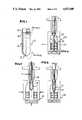
- FIG. 1is an elevational view with parts broken away of a preform formed in accordance with this invention.
- FIG. 2is a schematic sectional view showing the preform of FIG. 1 initially being placed in a blow mold.
- FIG. 3is another schematic vertical sectional view similar to FIG. 2 and shows a mechanical axial elongation of the preform.
- FIG. 4is yet another schematic vertical sectional view showing the previously axially elongated preform being blow molded to match the configuration of the blow mold.
- FIG. 5is an enlarged fragmentary sectional view of that portion of the preform identified in FIG. 1.
- FIG. 6is an enlarged fragmentary vertical sectional view of that form of the preform identified in FIG. 1.
- FIG. 7is an enlarged fragmentary sectional view of the upper portion of the preform as shown in FIG. 5 after the preform has been stretched in the manner shown in FIG. 3.
- FIG. 8is an enlarged fragmentary sectional view of the lower part of the preform shown in FIG. 6 after the axial elongation of the preform as shown in FIG. 3.
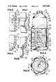
- FIG. 9is an elevational view with parts broken away and shown in section of a container formed in accordance with this invention in the blow mold as shown in FIG. 4 and having a label applied to the body thereof.
- FIG. 10is a horizontal sectional view taken generally along the line 10--10 of FIG. 9 and shows further the details of the container and the associated label.
- the preform 10is injection molded of a polyester resin with particular reference being made to PET (polyethylene terephthalate).
- PETpolyethylene terephthalate
- the various portions of the preform 10may be identified as including a base portion 12, a body portion 14, a neck finish portion 16 and a neck to body transition 18.
- the illustrated neck finish portion 16is in the form of a conventional neck finish which may include external threads 20 for receiving a closure, a locking bead 22 for engagement by a closure tamper indicating ring or band, and a lower flange 24.
- the neck to body transition 18Immediately below the flange 24 is the neck to body transition 18. It starts with an internal thickening to define a seat 26 for receiving, for example, a blow nozzle in seated engagement. Immediately below the seat, the transition may include a cylindrical part 28. Below the cylindrical part 28, the transition 18 downwardly tapers in thickness externally as at 30 terminating in a further cylindrical part 32 of minimal cross section. Below the cylindrical part 32, the transition 18 flares both internally and externally as at 34 to join the greater thickness body portion 14.
- the base portionbegins at the lower end of the body 14 with a radius part 36 which joins a frustoconical part 38 to the body portion 14.
- the frustoconical partin turn, carries a part spherical bottom 40 which tapers in thickness from the frustoconical part 38.
- the preform 10is formed by injection molding and when presented to the blow molding apparatus (not shown) is at room temperature.
- a preformin a normal blow molding operation, is heated by a series of quartz heaters which results in the heating of the outer surface of the preform to a higher temperature than the inner surface.
- radio frequency heatinghas been utilized with the result that the inner surface of the preform is heated to a higher temperature.
- Hybrid heatingutilizing a combination of quartz heaters and radio frequency heaters has been utilized in the past to obtain a uniform temperature throughout the wall of the preform. Such a heating process is disclosed in U.S. Pat. No. 4,407,651.
- the preform 10will be reheated first utilizing a quartz oven or like quartz heater with this first reheating treatment resulting in the outside surface temperature of the preform rising to on the order of 240° F. while the inside surface of the preform is only slightly heated to a temperature on the order of 120° F.
- the temperature of the center of the body wall of the preformis only slightly greater than the inside surface temperature and is on the order of 140° F.
- the initial reheating timeis on the order of 14.5 seconds.
- the reheatingis discontinued and the preform is permitted to equilibrate for a period of time on the order of 5 seconds.
- the temperature of the outside surface of the preform bodycontinues to increase to a temperature on the order of 250° F. and then begins to cool down to a temperature on the order of 230° F.
- the temperature of the center of the preform bodyremains generally constant while the temperature of the inside surface of the preform body increases gradually to a temperature on the order of 135° F., the temperature of the inside surface of the preform body approaching that of the center of the preform body.
- further reheating of the preformbe also by way of a quartz heater for a reheating period.
- the time of this further quartz reheatingis on the order of 12.5 seconds and during this second period of quartz reheating, the temperature of the exterior surface of the preform body continues to rise above the temperature of the center of the preform body and the inside surface of the preform body.
- the exterior surface temperaturerises to on the order of 350° F. while the inside surface temperature slowly gradually rises to a temperature on the order of 180° F. and the temperature at the center of the preform wall slowly rises at a slightly greater rate to a temperature on the order of 220° F.
- the temperature of the exterior surface of the preform bodyis much greater than that of the interior surface and the temperature at the center of the preform body has also gradually increased above that of the interior surface of the preform body.
- the preform bodyis immediately thereafter further reheated by way of radio frequency heating. While the temperature of the outside surface of the preform body rises only slightly during the radio frequency heating, the heating of the inside surface of the preform body very rapidly increases from the temperature generally on the order of 160° F. to a temperature slightly greater than 300° F.
- the time of radio frequency heatingis on the order of 2 seconds. During this time there is only a minor increase in the temperature of the preform body at the center of the cross section thereof to a temperature on the order of 240° F. Thus the temperature of the center of the preform body cross section is the lowest and the temperatures of the inside surface and outside surface are greater.
- blow molding stepsare initiated with there being a total lapse of time on the order of 6 seconds. During these 6 seconds, there is a second equilibration of the preform.
- the temperature of the outside surfaces of the preform bodywill rapidly decrease to a temperature on the order of, but below 280° F.
- the temperature on the inside surface of the preform bodywill continue to increase and then taper off to a temperature on the order of 350° F.
- the temperature of the preform at the center of the body cross sectionwill rise and then taper off at a temperature on the order of 260° F. It will thus be seen that the temperature at the center of the cross section of the preform body is still the lowest, but the temperature of the outside surface is only slightly greater.
- the desired high reheat temperaturemay be obtained in accordance with this reheating method without the undesired surface crystallization.
- the customary centering rod 44is directed down into the preform 10 and engages the bottom part 40.
- the rod 44is utilized to elongate the preform on the order of 25 percent, as is shown in FIG. 3.
- the results of this elongation of the preform 10are best shown in FIGS. 7 and 8. Since the reheating of the preform 10 stops on the order of 2 mm below the flange 24, and since the preform is supported against axial movement within the blow mold by the flange 24, there is no deformation or elongation of the neck finish portion 16. On the other hand, since the central part of the neck to body transition 18 is of minimum cross section, it will be seen that there will be considerable elongation of the neck to body transition 18.
- the preform 10having been elongated on the order of 25 percent, is now ready for the introduction of a blow gas so that the preform 10 may be inflated in the customary manner to match the configuration of the blow mold 42. If desired, during the inflation of the stretched preform 10, the stretch rod 44 may be permitted to follow the axial elongation of the preform during inflation so as to make certain that the base portion 12 of the preform remains centered relative to the blow mold.
- the inflation of the preform 10 within the blow mold 42results in the formation of a container in the form of a bottle generally identified by the numeral 54.
- the shape of the container or bottle 54is also critical in the hot fill shrinkage thereof.
- the bottle 54will have a neck finish which is identical with the original neck finish 16 of the preform 10 including the flange 24 and a portion of the preform immediately below the flange which was not heated, as previously described. This portion is generally in accordance with the previously described part 28 of the preform.
- the bottle 54also includes a downwardly and outwardly sloping shoulder portion 56 which is formed from the previously stretched neck to body transition portion 18.
- the shoulder portion 56in conventional container constructions is generally of a low orientation and is gradually formed during the inflation of the preform. However, inasmuch as the shoulder portion 56 is defined by that part of the preform which was very rapidly mechanically stretched followed by the inflation of the preform, the shoulder portion 56 has a high strain crystallization.
- the shoulder portion 56is connected by a radius 58 to an upper body portion 60 which flares slightly outwardly and downwardly.
- the upper body portion 60terminates in a radially inwardly directed rib 62 which, in turn, is connected to a generally cylindrical main body portion 64.
- the main body portion 64includes upper and lower cylindrical bands 66, 68 with the body portion 64 between the bands 66, 68 including a plurality of radially inwardly recessed vacuum pressure panels 70.
- Each pressure panel 70as is best shown in FIG. 9, is of a vertically elongated rectangular configuration with rounded corners and is generally chordal in configuration.
- Each pressure panel 70is reinforced against deformation by a plurality of transverse horizontally extending radially recessed ribs 72 which are also of an elongated rectangular outline, but the elongation being in the horizontal or circumferential direction.
- Adjacent pressure deformable vacuum panels 70are separated by a vertically elongated land area 74.
- Each land area 74extends between the bands 66, 68 and is reinforced by a vertically extending, radially inwardly directed rib 76.
- the bottle 54also includes a base 78 which includes a ribbed recessed bottom 80 which is joined to the body 64 by a rounded base portion 82.
- the ribbed bottomwhich is best shown in FIG. 10, may include five circumferentially spaced, radiating downwardly directed ribs 84 which are defined by the base configuration of the blow mold 42.
- the bands 66, 68are recessed radially inwardly a slight distance with respect to the lower part of the rib 62 and the rounded portion 82 of the base portion 78.
- the label 86bridges the recessed pressure deformable vacuum panel 70 so as to give the bottle 54 the appearance of one wherein the body portion 64 is cylindrical.
- the resultant bottle 54has in the body portions thereof a 28-30 percent sidewall crystallization which is a stress induced crystallization as opposed to being a temperature induced crystallization. Further, because of the specific cross sectional configuration of the body portion 64 as well as the specific stress induced crystallization of the shoulder portion 56, when the bottle 54 is hot filled with a liquid at a temperature on the order of 180°-185° F., the shrinkage of the bottle 54 by volume will be no greater than 1 percent, i.e.
- the volumetric shrinkageshould be between 0 and 1 percent.
- the bottle 54when hot filled with a heated liquid, will maintain this configuration.
- the neck finish 16is non-oriented, it will be subjected to heat deformation.
- the neck finish 16is injection molded and relatively thick, it will be able to withstand the momentary heating thereof to a relatively high temperature without deformation which will prevent the closing and sealing of the bottle 54 utilizing conventional closures, particularly screw threaded closures.
- the recessed bottom or base portion 80is of a relatively thick wall configuration and will resist deformation when the bottle 54 is filled with a heated liquid.
Landscapes
- Engineering & Computer Science (AREA)
- Mechanical Engineering (AREA)
- Manufacturing & Machinery (AREA)
- Physics & Mathematics (AREA)
- Geometry (AREA)
- Ceramic Engineering (AREA)
- Thermal Sciences (AREA)
- Blow-Moulding Or Thermoforming Of Plastics Or The Like (AREA)
Abstract
Description
Claims (14)
Priority Applications (1)
| Application Number | Priority Date | Filing Date | Title |
|---|---|---|---|
| US07/336,417US4927680A (en) | 1987-12-24 | 1989-04-11 | Preform and method of forming container therefrom |
Applications Claiming Priority (2)
| Application Number | Priority Date | Filing Date | Title |
|---|---|---|---|
| US07/137,565US4863046A (en) | 1987-12-24 | 1987-12-24 | Hot fill container |
| US07/336,417US4927680A (en) | 1987-12-24 | 1989-04-11 | Preform and method of forming container therefrom |
Related Parent Applications (1)
| Application Number | Title | Priority Date | Filing Date |
|---|---|---|---|
| US07/137,565DivisionUS4863046A (en) | 1987-12-24 | 1987-12-24 | Hot fill container |
Publications (1)
| Publication Number | Publication Date |
|---|---|
| US4927680Atrue US4927680A (en) | 1990-05-22 |
Family
ID=26835363
Family Applications (1)
| Application Number | Title | Priority Date | Filing Date |
|---|---|---|---|
| US07/336,417Expired - LifetimeUS4927680A (en) | 1987-12-24 | 1989-04-11 | Preform and method of forming container therefrom |
Country Status (1)
| Country | Link |
|---|---|
| US (1) | US4927680A (en) |
Cited By (38)
| Publication number | Priority date | Publication date | Assignee | Title |
|---|---|---|---|---|
| US5145632A (en)* | 1989-06-29 | 1992-09-08 | Sidel | Process for the manufacture of pet containers designed to be filled with a hot liquid |
| US5158817A (en)* | 1990-04-12 | 1992-10-27 | Continental Pet Technologies, Inc. | Method of forming the base section of oblong or oval containers and a preform for effecting same |
| WO1994006618A1 (en)* | 1992-09-22 | 1994-03-31 | Pepsico, Inc. | Blow molding preform, process and apparatus |
| US5304340A (en)* | 1991-09-06 | 1994-04-19 | C. R. Bard, Inc. | Method of increasing the tensile strength of a dilatation balloon |
| US5427258A (en)* | 1992-04-09 | 1995-06-27 | Continental Pet Technologies, Inc. | Freestanding container with improved combination of properties |
| US5472660A (en)* | 1989-03-08 | 1995-12-05 | Fortex, Inc. | Method for the manufacture of shaped products of biaxially oriented polymeric material |
| US5484072A (en)* | 1994-03-10 | 1996-01-16 | Hoover Universal, Inc. | Self-standing polyester containers for carbonated beverages |
| US5614148A (en)* | 1995-01-30 | 1997-03-25 | Dtl Technology Limited Partnership | One piece self-standing blow molded plastic containers made from a monobase preform |
| US5683648A (en)* | 1992-03-25 | 1997-11-04 | Design Technology, Inc. | Thermoforming and heat shrinking for forming containers |
| US6093364A (en)* | 1989-03-08 | 2000-07-25 | Fortex, Inc. | Method for producing a biaxially oriented open-ended container |
| US20030161980A1 (en)* | 2002-02-27 | 2003-08-28 | Nelson Brent S. | Plastic container |
| US20030194518A1 (en)* | 2002-04-12 | 2003-10-16 | Nahill Thomas E. | Graded crystallization of container finishes |
| USD488723S1 (en) | 2002-05-09 | 2004-04-20 | Stokely-Van Camp, Inc. | Bottle portion |
| USD488722S1 (en) | 2002-05-09 | 2004-04-20 | Stokely-Van Camp, Inc. | Bottle |
| US20040202745A1 (en)* | 2003-04-11 | 2004-10-14 | Wentworth Mold Inc. | Hot fill mold shell assembly with reduced heat transfer |
| US20040202746A1 (en)* | 2003-04-11 | 2004-10-14 | Wentworth Mold Inc. | Mold assembly with modular mold shells |
| USD504063S1 (en) | 2002-10-18 | 2005-04-19 | Stokely-Van Camp, Inc. | Bottle |
| USD504619S1 (en) | 2002-10-18 | 2005-05-03 | Stokely-Van Camp, Inc. | Bottle |
| US20050158495A1 (en)* | 2003-12-24 | 2005-07-21 | Nahill Thomas E. | Lightweight container and method of manufacture |
| US20060051541A1 (en)* | 2004-09-09 | 2006-03-09 | Steele Scott W | Polymeric preform for a blow molded plastic article |
| WO2007109910A1 (en)* | 2006-03-29 | 2007-10-04 | Fostag Holding Ag | Preform and pet bottle produced therefrom |
| US20080257855A1 (en)* | 2007-04-19 | 2008-10-23 | Graham Packaging Company, Lp | Preform Base and Method of Making a Delamination and Crack Resistant Multilayer Container Base |
| US20090155501A1 (en)* | 2007-12-14 | 2009-06-18 | Husky Injection Molding Systems Ltd. | Preform and a Mold Stack for Producing the Preform |
| US20100260886A1 (en)* | 2007-12-14 | 2010-10-14 | Husky Injection Molding Systems Ltd. | Preform and a mold stack for producing the preform |
| US8070470B2 (en) | 2009-02-06 | 2011-12-06 | Wentworth Mold Ltd. | Mold assembly |
| EP2463079A1 (en)* | 2010-12-10 | 2012-06-13 | Nestec S.A. | A process for single-step forming and filling of containers |
| USD664165S1 (en) | 2009-02-17 | 2012-07-24 | Husky Injection Molding Systems Ltd. | Gate portion of a preform |
| US20130244050A1 (en)* | 2010-12-09 | 2013-09-19 | Husky Injection Molding System Ltd. | Preform and a mold stack for producing the preform |
| WO2020028405A1 (en)* | 2018-07-30 | 2020-02-06 | Niagara Bottling, Llc | Container preform with threaded tamper evidence finish |
| US11214410B2 (en) | 2016-02-02 | 2022-01-04 | Niagara Bottling, Llc | Tamper evidence container closure |
| US11472093B2 (en) | 2019-02-26 | 2022-10-18 | Niagara Bottling, Llc | Nozzle for blow-molding stepped finish preform |
| US11591129B2 (en) | 2010-11-12 | 2023-02-28 | Niagara Bottling, Llc | Preform extended finish for processing light weight ecologically beneficial bottles |
| US11597556B2 (en) | 2018-07-30 | 2023-03-07 | Niagara Bottling, Llc | Container preform with tamper evidence finish portion |
| US11738902B2 (en) | 2019-08-08 | 2023-08-29 | Niagara Bottling, Llc | Container preform with stepped interior finish |
| US11807413B2 (en) | 2019-10-03 | 2023-11-07 | Niagara Bottling, Llc | Container finish portion with polished buffer zone |
| US11827410B2 (en) | 2010-11-12 | 2023-11-28 | Niagara Bottling, Llc | Preform extended finish for processing light weight ecologically beneficial bottles |
| US12139295B2 (en) | 2021-03-12 | 2024-11-12 | Niagara Bottling, Llc | Container preform |
| US12263994B2 (en) | 2012-11-01 | 2025-04-01 | Niagara Bottling, Llc | Extended thread tamper band evidence |
Citations (8)
| Publication number | Priority date | Publication date | Assignee | Title |
|---|---|---|---|---|
| US4330579A (en)* | 1979-01-16 | 1982-05-18 | Yoshino Kogyosho Co., Ltd. | Parison for bottle product |
| US4406854A (en)* | 1978-12-13 | 1983-09-27 | Yoshino Kogyosho Co. Ltd. | Method of molding a bottle-shaped container of synthetic resin |
| GB2124543A (en)* | 1982-07-29 | 1984-02-22 | Owens Illinois Inc | Parison for oriented plastic containers |
| US4469775A (en)* | 1981-07-22 | 1984-09-04 | Basf Aktiengesellschaft | Multi-layer elements with polyvinyl alcohol overcoat suitable for the production of relief printing plates |
| US4618515A (en)* | 1985-04-05 | 1986-10-21 | Continental Pet Technologies, Inc. | Polyester container with oriented, crystallized thread finish for hot fill applications and method of making same |
| US4649068A (en)* | 1985-04-22 | 1987-03-10 | Continental Pet Technologies, Inc. | Preform for use in blow molding a container subjected to hot filling and closed by a rotatable closure, and method of an apparatus for making the same |
| US4725464A (en)* | 1986-05-30 | 1988-02-16 | Continental Pet Technologies, Inc. | Refillable polyester beverage bottle and preform for forming same |
| US4755404A (en)* | 1986-05-30 | 1988-07-05 | Continental Pet Technologies, Inc. | Refillable polyester beverage bottle and preform for forming same |
- 1989
- 1989-04-11USUS07/336,417patent/US4927680A/ennot_activeExpired - Lifetime
Patent Citations (8)
| Publication number | Priority date | Publication date | Assignee | Title |
|---|---|---|---|---|
| US4406854A (en)* | 1978-12-13 | 1983-09-27 | Yoshino Kogyosho Co. Ltd. | Method of molding a bottle-shaped container of synthetic resin |
| US4330579A (en)* | 1979-01-16 | 1982-05-18 | Yoshino Kogyosho Co., Ltd. | Parison for bottle product |
| US4469775A (en)* | 1981-07-22 | 1984-09-04 | Basf Aktiengesellschaft | Multi-layer elements with polyvinyl alcohol overcoat suitable for the production of relief printing plates |
| GB2124543A (en)* | 1982-07-29 | 1984-02-22 | Owens Illinois Inc | Parison for oriented plastic containers |
| US4618515A (en)* | 1985-04-05 | 1986-10-21 | Continental Pet Technologies, Inc. | Polyester container with oriented, crystallized thread finish for hot fill applications and method of making same |
| US4649068A (en)* | 1985-04-22 | 1987-03-10 | Continental Pet Technologies, Inc. | Preform for use in blow molding a container subjected to hot filling and closed by a rotatable closure, and method of an apparatus for making the same |
| US4725464A (en)* | 1986-05-30 | 1988-02-16 | Continental Pet Technologies, Inc. | Refillable polyester beverage bottle and preform for forming same |
| US4755404A (en)* | 1986-05-30 | 1988-07-05 | Continental Pet Technologies, Inc. | Refillable polyester beverage bottle and preform for forming same |
Cited By (71)
| Publication number | Priority date | Publication date | Assignee | Title |
|---|---|---|---|---|
| US6555047B1 (en) | 1989-03-08 | 2003-04-29 | Fortex, Inc. | Method for producing a biaxially oriented open ended container |
| US5472660A (en)* | 1989-03-08 | 1995-12-05 | Fortex, Inc. | Method for the manufacture of shaped products of biaxially oriented polymeric material |
| US6093364A (en)* | 1989-03-08 | 2000-07-25 | Fortex, Inc. | Method for producing a biaxially oriented open-ended container |
| US5145632A (en)* | 1989-06-29 | 1992-09-08 | Sidel | Process for the manufacture of pet containers designed to be filled with a hot liquid |
| US5158817A (en)* | 1990-04-12 | 1992-10-27 | Continental Pet Technologies, Inc. | Method of forming the base section of oblong or oval containers and a preform for effecting same |
| US5304340A (en)* | 1991-09-06 | 1994-04-19 | C. R. Bard, Inc. | Method of increasing the tensile strength of a dilatation balloon |
| US5683648A (en)* | 1992-03-25 | 1997-11-04 | Design Technology, Inc. | Thermoforming and heat shrinking for forming containers |
| US5427258A (en)* | 1992-04-09 | 1995-06-27 | Continental Pet Technologies, Inc. | Freestanding container with improved combination of properties |
| US5560943A (en)* | 1992-09-22 | 1996-10-01 | Pepsico., Inc. | Apparatus for annealing and blowing a thermoplastic biaxially oriented container |
| US5660905A (en)* | 1992-09-22 | 1997-08-26 | Pepsico., Inc. | Preform and process and apparatus for annealing biaxially oriented hollow shaped thermoplastic articles |
| US5547631A (en)* | 1992-09-22 | 1996-08-20 | Pepsico., Inc. | Process for annealing biaxially oriented hollow shaped thermoplastic atricles |
| WO1994006618A1 (en)* | 1992-09-22 | 1994-03-31 | Pepsico, Inc. | Blow molding preform, process and apparatus |
| US5484072A (en)* | 1994-03-10 | 1996-01-16 | Hoover Universal, Inc. | Self-standing polyester containers for carbonated beverages |
| US5614148A (en)* | 1995-01-30 | 1997-03-25 | Dtl Technology Limited Partnership | One piece self-standing blow molded plastic containers made from a monobase preform |
| US20030161980A1 (en)* | 2002-02-27 | 2003-08-28 | Nelson Brent S. | Plastic container |
| US20100084359A1 (en)* | 2002-02-27 | 2010-04-08 | Tropicana Products, Inc. | Plastic Container |
| US7033656B2 (en) | 2002-04-12 | 2006-04-25 | Graham Packaging Pet Technologies, Inc. | Graded crystallization of container finishes |
| US20030194518A1 (en)* | 2002-04-12 | 2003-10-16 | Nahill Thomas E. | Graded crystallization of container finishes |
| US20060110558A1 (en)* | 2002-04-12 | 2006-05-25 | Graham Packaging Pet Technologies, Inc. | Graded crystallization of container finishes |
| USD488722S1 (en) | 2002-05-09 | 2004-04-20 | Stokely-Van Camp, Inc. | Bottle |
| USD488723S1 (en) | 2002-05-09 | 2004-04-20 | Stokely-Van Camp, Inc. | Bottle portion |
| USD507743S1 (en) | 2002-10-18 | 2005-07-26 | Stokely-Van Camp, Inc. | Bottle |
| USD512308S1 (en) | 2002-10-18 | 2005-12-06 | Stokely-Van Camp, Inc. | Bottle |
| USD504619S1 (en) | 2002-10-18 | 2005-05-03 | Stokely-Van Camp, Inc. | Bottle |
| USD507491S1 (en) | 2002-10-18 | 2005-07-19 | Stokely-Van Camp, Inc. | Bottle |
| USD510526S1 (en) | 2002-10-18 | 2005-10-11 | Stokely-Van Camp, Inc. | Bottle |
| USD504063S1 (en) | 2002-10-18 | 2005-04-19 | Stokely-Van Camp, Inc. | Bottle |
| USD514449S1 (en) | 2002-10-18 | 2006-02-07 | Stokely-Van Camp, Inc. | Bottle |
| USD510706S1 (en) | 2002-10-18 | 2005-10-18 | Stokely-Van Camp, Inc. | Bottle |
| USD506677S1 (en) | 2002-10-18 | 2005-06-28 | Stokely-Van Camp, Inc. | Bottle |
| US6948924B2 (en) | 2003-04-11 | 2005-09-27 | Wentworth Mold Inc. | Mold assembly with modular mold shells |
| US20040202746A1 (en)* | 2003-04-11 | 2004-10-14 | Wentworth Mold Inc. | Mold assembly with modular mold shells |
| US20040202745A1 (en)* | 2003-04-11 | 2004-10-14 | Wentworth Mold Inc. | Hot fill mold shell assembly with reduced heat transfer |
| US6913455B2 (en) | 2003-04-11 | 2005-07-05 | Wentworth Mold Inc. | Hot fill mold shell assembly with reduced heat transfer |
| US20050158495A1 (en)* | 2003-12-24 | 2005-07-21 | Nahill Thomas E. | Lightweight container and method of manufacture |
| US20060051541A1 (en)* | 2004-09-09 | 2006-03-09 | Steele Scott W | Polymeric preform for a blow molded plastic article |
| WO2007109910A1 (en)* | 2006-03-29 | 2007-10-04 | Fostag Holding Ag | Preform and pet bottle produced therefrom |
| US8020717B2 (en) | 2007-04-19 | 2011-09-20 | Graham Packaging Company, Lp | Preform base and method of making a delamination and crack resistant multilayer container base |
| US20080257855A1 (en)* | 2007-04-19 | 2008-10-23 | Graham Packaging Company, Lp | Preform Base and Method of Making a Delamination and Crack Resistant Multilayer Container Base |
| US20090155501A1 (en)* | 2007-12-14 | 2009-06-18 | Husky Injection Molding Systems Ltd. | Preform and a Mold Stack for Producing the Preform |
| US7897222B2 (en) | 2007-12-14 | 2011-03-01 | Husky Injection Molding Systems Ltd. | Preform and a mold stack for producing the preform |
| US20100260886A1 (en)* | 2007-12-14 | 2010-10-14 | Husky Injection Molding Systems Ltd. | Preform and a mold stack for producing the preform |
| US8241718B2 (en) | 2007-12-14 | 2012-08-14 | Husky Injection Molding Systems Ltd. | Preform and a mold stack for producing the preform |
| US8070470B2 (en) | 2009-02-06 | 2011-12-06 | Wentworth Mold Ltd. | Mold assembly |
| USD664165S1 (en) | 2009-02-17 | 2012-07-24 | Husky Injection Molding Systems Ltd. | Gate portion of a preform |
| USD702743S1 (en) | 2009-02-17 | 2014-04-15 | Husky Injection Molding Systems Ltd. | Gate portion of a preform |
| US12246877B2 (en) | 2010-11-12 | 2025-03-11 | Niagara Bottling, Llc | Preform extended finish for processing light weight ecologically beneficial bottles |
| US11827410B2 (en) | 2010-11-12 | 2023-11-28 | Niagara Bottling, Llc | Preform extended finish for processing light weight ecologically beneficial bottles |
| US11591129B2 (en) | 2010-11-12 | 2023-02-28 | Niagara Bottling, Llc | Preform extended finish for processing light weight ecologically beneficial bottles |
| US9358710B2 (en)* | 2010-12-09 | 2016-06-07 | Husky Injection Molding Systems Ltd. | Preform and a mold stack for producing the preform |
| US20130244050A1 (en)* | 2010-12-09 | 2013-09-19 | Husky Injection Molding System Ltd. | Preform and a mold stack for producing the preform |
| CN103260854A (en)* | 2010-12-10 | 2013-08-21 | 雀巢产品技术援助有限公司 | A process for single-step forming and filling of containers |
| EP2463079A1 (en)* | 2010-12-10 | 2012-06-13 | Nestec S.A. | A process for single-step forming and filling of containers |
| RU2602106C2 (en)* | 2010-12-10 | 2016-11-10 | Дискма Аг | Method for single-stap forming and filling of containers |
| US10189586B2 (en) | 2010-12-10 | 2019-01-29 | Discma Ag | Process for single-step forming and filling of containers |
| WO2012076576A3 (en)* | 2010-12-10 | 2012-08-16 | Nestec S.A. | A process for single-step forming and filling of containers |
| CN103260854B (en)* | 2010-12-10 | 2016-06-01 | 帝斯克玛股份有限公司 | Single-step forming and filling process for containers |
| US12263994B2 (en) | 2012-11-01 | 2025-04-01 | Niagara Bottling, Llc | Extended thread tamper band evidence |
| US11214410B2 (en) | 2016-02-02 | 2022-01-04 | Niagara Bottling, Llc | Tamper evidence container closure |
| US12234052B2 (en) | 2018-07-30 | 2025-02-25 | Niagara Bottling, Llc | Container preform with tamper evidence finish portion |
| US11597556B2 (en) | 2018-07-30 | 2023-03-07 | Niagara Bottling, Llc | Container preform with tamper evidence finish portion |
| US12246885B2 (en) | 2018-07-30 | 2025-03-11 | Niagara Bottling, Llc | Container preform with threaded tamper evidence finish |
| EP3829985A4 (en)* | 2018-07-30 | 2022-03-09 | Niagara Bottling, LLC | CONTAINER PREFORM WITH CONTAINER WITH THREADED TITCHING TREATMENT |
| WO2020028405A1 (en)* | 2018-07-30 | 2020-02-06 | Niagara Bottling, Llc | Container preform with threaded tamper evidence finish |
| US11806917B2 (en) | 2019-02-26 | 2023-11-07 | Niagara Bottling, Llc | Nozzle for blow-molding stepped finish preform |
| US11472093B2 (en) | 2019-02-26 | 2022-10-18 | Niagara Bottling, Llc | Nozzle for blow-molding stepped finish preform |
| US11738902B2 (en) | 2019-08-08 | 2023-08-29 | Niagara Bottling, Llc | Container preform with stepped interior finish |
| US12240650B2 (en) | 2019-08-08 | 2025-03-04 | Niagara Bottling, Llc | Container preform with stepped interior finish |
| US11807413B2 (en) | 2019-10-03 | 2023-11-07 | Niagara Bottling, Llc | Container finish portion with polished buffer zone |
| US12304688B2 (en) | 2019-10-03 | 2025-05-20 | Niagara Bottling, Llc | Container finish portion with polished buffer zone |
| US12139295B2 (en) | 2021-03-12 | 2024-11-12 | Niagara Bottling, Llc | Container preform |
Similar Documents
| Publication | Publication Date | Title |
|---|---|---|
| US4863046A (en) | Hot fill container | |
| US4927680A (en) | Preform and method of forming container therefrom | |
| JP3047732B2 (en) | Manufacturing method of biaxially stretched blow container | |
| US4665682A (en) | Method for producing a hot fillable, collapse resistant polyester container without the need to utilize set process techniques and/or non-conventional container geometries | |
| KR100225007B1 (en) | Self-standing container having excellent heat resistance and pressure resistance and method of producing the same | |
| US4379099A (en) | Method for producing polyester container | |
| US5884792A (en) | Preform for a hot fill pressure container | |
| US6062408A (en) | Wide mouth hot fill container | |
| US4785948A (en) | Blow molded plastic container having a reinforced wall structure and preform therefor | |
| JPH0688315B2 (en) | Primary blow-molded products for heat-resistant hollow containers | |
| US4880593A (en) | Method for preparing blow molded plastic container | |
| EP0365945B1 (en) | Container | |
| US4885197A (en) | Plastic preform for forming blow molded plastic bottles | |
| WO2016059135A1 (en) | Preform having a variable thickness around a main axis | |
| JPH085117B2 (en) | Pressure-resistant thin synthetic resin container and method of molding the same | |
| JPH10146880A (en) | Method for producing polyethylene terephthalate resin bottle | |
| CA1332155C (en) | Hot fill container | |
| NZ245610A (en) | Hot fill blow moulded container with vacuum deformable panels | |
| JPH08244745A (en) | Container with cap | |
| JP3178538B2 (en) | Biaxially stretch blow molded bottle and molding method | |
| JPH0365247B2 (en) | ||
| JP2002067129A (en) | Biaxially stretched polyester bottle and its manufacturing method | |
| JPH0622862B2 (en) | Heat-resistant pressure-resistant container and manufacturing method thereof | |
| JPH07304089A (en) | Manufacture of biaxially oriented blow vessel whose bottom is strengthened | |
| JPH0240499B2 (en) |
Legal Events
| Date | Code | Title | Description |
|---|---|---|---|
| FEPP | Fee payment procedure | Free format text:PAYOR NUMBER ASSIGNED (ORIGINAL EVENT CODE: ASPN); ENTITY STATUS OF PATENT OWNER: LARGE ENTITY | |
| STCF | Information on status: patent grant | Free format text:PATENTED CASE | |
| FEPP | Fee payment procedure | Free format text:PAYER NUMBER DE-ASSIGNED (ORIGINAL EVENT CODE: RMPN); ENTITY STATUS OF PATENT OWNER: LARGE ENTITY Free format text:PAYOR NUMBER ASSIGNED (ORIGINAL EVENT CODE: ASPN); ENTITY STATUS OF PATENT OWNER: LARGE ENTITY | |
| FPAY | Fee payment | Year of fee payment:4 | |
| FPAY | Fee payment | Year of fee payment:8 | |
| FEPP | Fee payment procedure | Free format text:PAYOR NUMBER ASSIGNED (ORIGINAL EVENT CODE: ASPN); ENTITY STATUS OF PATENT OWNER: LARGE ENTITY Free format text:PAYER NUMBER DE-ASSIGNED (ORIGINAL EVENT CODE: RMPN); ENTITY STATUS OF PATENT OWNER: LARGE ENTITY | |
| FEPP | Fee payment procedure | Free format text:PAYER NUMBER DE-ASSIGNED (ORIGINAL EVENT CODE: RMPN); ENTITY STATUS OF PATENT OWNER: LARGE ENTITY Free format text:PAYOR NUMBER ASSIGNED (ORIGINAL EVENT CODE: ASPN); ENTITY STATUS OF PATENT OWNER: LARGE ENTITY | |
| FPAY | Fee payment | Year of fee payment:12 | |
| AS | Assignment | Owner name:DEUTSCHE BANK AG CAYMAN ISLANDS BRANCH AS SECOND-L Free format text:GRANT OF SECURITY INTEREST;ASSIGNOR:GRAHAM PACKAGING COMPANY, L.P.;REEL/FRAME:015552/0299 Effective date:20041007 Owner name:DEUTSCHE BANK AG CAYMAN ISLANDS BRANCH, NEW JERSEY Free format text:GRANT OF SECURITY INTEREST;ASSIGNOR:GRAHAM PACKAGING COMPANY, L.P.;REEL/FRAME:015980/0213 Effective date:20041007 | |
| AS | Assignment | Owner name:GRAHAM PACKAGING PET TECHNOLOGIES INC., PENNSYLVAN Free format text:CHANGE OF NAME;ASSIGNOR:CONTINENTAL PET TECHNOLOGIES, INC.;REEL/FRAME:018047/0970 Effective date:20041012 | |
| AS | Assignment | Owner name:GRAHAM PACKAGING COMPANY, L.P., PENNSYLVANIA Free format text:PATENT RELEASE;ASSIGNOR:DEUTSCHE BANK AG, CAYMAN ISLANDS BRANCH, AS COLLATERAL AGENT;REEL/FRAME:019140/0509 Effective date:20070330 | |
| AS | Assignment | Owner name:GRAHAM PACKAGING COMPANY, L.P., PENNSYLVANIA Free format text:RELEASE OF SECURITY INTERESTS;ASSIGNOR:DEUTSCHE BANK AG, GAYMAN ISLANDS BRANCH, AS COLLATERAL AGENT;REEL/FRAME:027011/0572 Effective date:20110908 | |
| AS | Assignment | Owner name:GRAHAM PACKAGING COMPANY, L.P., PENNSYLVANIA Free format text:RELEASE OF SECURITY INTEREST IN CERTAIN PATENT COLLATERAL;ASSIGNOR:DEUTSCHE BANK AG CAYMAN ISLANDS BRANCH, AS COLLATERAL AGENT AND GRANTEE;REEL/FRAME:053414/0001 Effective date:20200805 |