US4927425A - Surgical rod pusher instrument - Google Patents
Surgical rod pusher instrumentDownload PDFInfo
- Publication number
- US4927425A US4927425AUS07/287,243US28724388AUS4927425AUS 4927425 AUS4927425 AUS 4927425AUS 28724388 AUS28724388 AUS 28724388AUS 4927425 AUS4927425 AUS 4927425A
- Authority
- US
- United States
- Prior art keywords
- rod
- recess
- instrument
- receiving opening
- cavity
- Prior art date
- Legal status (The legal status is an assumption and is not a legal conclusion. Google has not performed a legal analysis and makes no representation as to the accuracy of the status listed.)
- Expired - Lifetime
Links
Images
Classifications
- A—HUMAN NECESSITIES
- A61—MEDICAL OR VETERINARY SCIENCE; HYGIENE
- A61B—DIAGNOSIS; SURGERY; IDENTIFICATION
- A61B17/00—Surgical instruments, devices or methods
- A61B17/56—Surgical instruments or methods for treatment of bones or joints; Devices specially adapted therefor
- A61B17/58—Surgical instruments or methods for treatment of bones or joints; Devices specially adapted therefor for osteosynthesis, e.g. bone plates, screws or setting implements
- A61B17/68—Internal fixation devices, including fasteners and spinal fixators, even if a part thereof projects from the skin
- A61B17/70—Spinal positioners or stabilisers, e.g. stabilisers comprising fluid filler in an implant
- A61B17/7074—Tools specially adapted for spinal fixation operations other than for bone removal or filler handling
- A61B17/7083—Tools for guidance or insertion of tethers, rod-to-anchor connectors, rod-to-rod connectors, or longitudinal elements
Definitions
- the present inventionrelates to a surgical instrument having a plurality of rod locator recesses.
- the instrumentis used to aid in manually manipulating a rod by pushing or pulling or generally applying force to that rod.
- the instrumenthas the ability to be used to apply such force in multiple planes or multiple directions by selecting the desired rod locator recess, so that force can accordingly be applied in the desired direction.
- the instrumentis particularly suitable for use with spinal implants and instrumentation, although it is not limited thereto.
- a rod driver or pushersuch as the instrument 901 shown in FIG. 1 which includes distal tip 905 having a single rod locator recess 910.
- a forcecan be applied against the rod in only a direction which is generally axially aligned with the longitudinal axis of the handle and directed toward the tip end. If a lateral or sideways force is applied to the rod, there is a likelihood that the instrument will slip off the rod. This is not desirable when applying such force on a rod at a surgical site.
- a principal object of the inventionis to provide a surgical rod pusher instrument which is capable of applying force to a rod in multiple planes or directions, thus providing controlled manual manipulation of the rod via the rod pusher instrument.
- a further object of the inventionis to provide a surgical rod pusher instrument which includes a plurality of rod locator recesses to enable the user to apply force to the rod in multiple, selectable directions.
- a still further object of the inventionis to provide an instrument which can be used to selectively apply forces to a rod in downward as well as in lateral (or sideways) and upwards directions.
- An additional object of the inventionis to provide an instrument which can be used to selectively apply forces to a rod in all 360° about the rod, as desired.
- the present inventionprovides a surgical rod pusher instrument for application of force against a rod.
- the instrumentincludes a distal tip with a handle extending therefrom.
- the tipincludes a rod receiving opening leading into an enlarged cavity.
- the cavityincludes a plurality of rod locator recesses. Each recess has a different directional orientation.
- the userselects the desired recess and locates the rod in the chosen recess and -hen applies a force against the rod in the desired direction.
- the plurality of recessesare oriented such that the instrument has the ability to apply force against the rod in a downward direction, as well as in both sideways (or lateral) directions, depending upon which rod locator recess is selected by the user.
- this instrumentcan selectively apply force against a rod in all 360° about the rod.
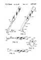
- FIG. 1is a perspective view of a prior art instrument
- FIG. 2is a perspective view of the surgical instrument according to the present invention.
- FIG. 3is a side view of the instrument of FIG. 2;
- FIG. 4is a top view of the instrument of FIG. 2;
- FIG. 5is a partial enlarged view of the distal tip of the instrument circled at "5" in FIG. 3;
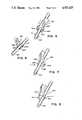
- FIGS. 6-9are perspective views illustrating the surgical instrument of FIG. 2 being utilized to apply force to a rod in various directions.
- FIGS. 2-5illustrate a particularly adVantageous embodiment of the surgical rod pusher instrument 601 of the present invention.
- FIGS. 6-9illustrate the use of this instrument 601 in conjunction with a rod 801, and illustrate the application of force to the rod 801 in various directions as represented by the arrows.
- this instrumentis particularly suitable for use as a spinal instrument, in particular for use with spinal implants which utilize a spinal rod (such as 801) for manipulating the rod during spinal surgery.
- the spinal rod 801may be utilized in conjunction with the spinal implant system described in co-pending patent application Ser. No. 07/287,245, filed Dec. 21, 1988 to Cozad et al. which is incorporated herein by reference.
- this surgical rod pusher instrumentmay be utilized with any suitable rod member, and is not limited to this particular spinal implant system, nor is it limited solely to spinal applications.
- this instrumentcould be utilized in conjunction with any suitable surgical rod or elongated member.
- the instrument 601includes a distal tip 605 or working end portion and an elongated handle 620 extending therefrom.
- the handlemay suitably include a gripping portion 622 which blends into a narrower portion 624 which attaches to the distal tip 605.
- the handlemay also include an enlarged proximal portion 623.
- the tip 605includes a rod receiving opening 610 leading into enlarged cavity 612.
- the cavityincludes a plurality of rod locator recesses 614, 615, and 616.
- the embodiment shownincludes three distinct rod locator recesses, first, second, and third recesses 614, 615, and 616, respectively.
- the enlarged cavity 612 and the rod receiving opening 610form a substantially cloverleaf-shaped opening, as shown in FIG. 5.
- the enlarged cavity 612could be substantially triangular in shape (not shown) with each angle of the triangle forming a respective rod locator recess and with the rod receiving opening 610 which leads into the cavity 612 being located along one leg of the triangle.
- embodiments utilizing two, four or more distinct recessescould also be utilized in keeping with the present invention.
- Each recess 614, 615, and 616has a different directional orientation.
- the rod locator recesses 614, 615, and 616each preferably have a shape which corresponds to the mating portion of the rod 801 which will be in contact or engagement with the selected recess.
- the rod 801is cylindrical and the corresponding rod locator recesses 614, 615, and 616 are each substantially semi-cylindrical and sized to accept the rod 801 as shown in FIGS. 6-9.
- the recessescould be formed as a suitable portion or segment of a curve as long as the recesses are adapted to receive the corresponding rod or elongated member 801
- a semi-circular recessis preferred over a smaller segment of a curve to help ensure secure location of the rod in the selected recess, and to lessen the likelihood of the rod slipping out of the recess when a force is applied to the instrument 601 against rod 801.
- Any suitable shapes for the recesses 614, 615, and 616 and for the corresponding mating rod 801could be utilized.
- the instrument 601could utilize recesses having different sizes (not shown) if it was desirable to utilize the instrument with varying sized rods 801.
- the width "w" of the rod receiving opening 610is suitably sized to allow the rod 801 having diameter "d” to pass through the opening 610 and into cavity 612.
- the first locator recess 614is located adjacent the second recess 615.
- Recess 615is also adjacent the third recess 616.
- An extended portion 630is formed in the instrument 601 between the first and second recesses 614, 615 and between the second and third recesses 615, 616, as shown in FIG. 5. These extended portions 630 extend from the instrument 601 in toward cavity 612, and assist in preventing the rod 801 from slipping from one recess to an adjacent recess.
- the first recess 614is adapted for application of a first generally sideways or lateral force to the rod 801 when the rod is located therein, as shown in FIG. 7. (The direction of force being applied is shown by arrow.)
- the second recess 615is adapted for application of a generally downward force on the rod 801 when the rod is located therein, as shown in FIG. 6. (The direction of force being applied is shown by arrow.)
- the third recess 616is adapted for application of a second generally sideways or lateral force to the rod 801 (as shown in FIG. 8) that is substantially opposite in direction to the first sideways force. It is noted that although the arrows in FIGS. 6, 7, and 8 indicate a force that is straight down vertically (FIG.
- instrument 601can selectively apply force against a rod in all 360° about the rod 801.
- the handle 620may angle in relation to the distal tip 605 at an angle of about 150°. This provides for better visualization of the surgical site by the user of the instrument 601.
- the tip 605may include a tip extension 608 interconnecting the tip 605 to the handle 620.
- the angle between the tip extension 608 and handle 620. as shown,is about 150°.
- the userpasses the rod 801 through the rod receiving opening 610 into the enlarged cavity 612. The user then selects one of the plurality of rod locator recesses 614, 615, and 616 and locates the rod 801 therein. Force is then applied against the rod in the appropriate desired direction.
- instrument 601.any suitable material may be utilized for instrument 601.
- One such materialis stainless steel.
- manufacturing methodsany suitable methods may be utilized.
Landscapes
- Health & Medical Sciences (AREA)
- Orthopedic Medicine & Surgery (AREA)
- Neurology (AREA)
- Life Sciences & Earth Sciences (AREA)
- Surgery (AREA)
- Heart & Thoracic Surgery (AREA)
- Engineering & Computer Science (AREA)
- Biomedical Technology (AREA)
- Nuclear Medicine, Radiotherapy & Molecular Imaging (AREA)
- Medical Informatics (AREA)
- Molecular Biology (AREA)
- Animal Behavior & Ethology (AREA)
- General Health & Medical Sciences (AREA)
- Public Health (AREA)
- Veterinary Medicine (AREA)
- Surgical Instruments (AREA)
- Prostheses (AREA)
Abstract
Description
The present invention relates to a surgical instrument having a plurality of rod locator recesses. The instrument is used to aid in manually manipulating a rod by pushing or pulling or generally applying force to that rod. The instrument has the ability to be used to apply such force in multiple planes or multiple directions by selecting the desired rod locator recess, so that force can accordingly be applied in the desired direction. The instrument is particularly suitable for use with spinal implants and instrumentation, although it is not limited thereto.
Heretofore, it is known to use a rod driver or pusher such as theinstrument 901 shown in FIG. 1 which includesdistal tip 905 having a single rod locator recess 910. By locating a rod in the recess, a force can be applied against the rod in only a direction which is generally axially aligned with the longitudinal axis of the handle and directed toward the tip end. If a lateral or sideways force is applied to the rod, there is a likelihood that the instrument will slip off the rod. This is not desirable when applying such force on a rod at a surgical site.
A principal object of the invention is to provide a surgical rod pusher instrument which is capable of applying force to a rod in multiple planes or directions, thus providing controlled manual manipulation of the rod via the rod pusher instrument.
A further object of the invention is to provide a surgical rod pusher instrument which includes a plurality of rod locator recesses to enable the user to apply force to the rod in multiple, selectable directions.
A still further object of the invention is to provide an instrument which can be used to selectively apply forces to a rod in downward as well as in lateral (or sideways) and upwards directions.
An additional object of the invention is to provide an instrument which can be used to selectively apply forces to a rod in all 360° about the rod, as desired.
The present invention provides a surgical rod pusher instrument for application of force against a rod. The instrument includes a distal tip with a handle extending therefrom. The tip includes a rod receiving opening leading into an enlarged cavity. The cavity includes a plurality of rod locator recesses. Each recess has a different directional orientation. The user selects the desired recess and locates the rod in the chosen recess and -hen applies a force against the rod in the desired direction. Preferably, the plurality of recesses are oriented such that the instrument has the ability to apply force against the rod in a downward direction, as well as in both sideways (or lateral) directions, depending upon which rod locator recess is selected by the user. Also, by proper manipulation of the instrument, it is possible to direct an upwards force on the rod, if desirable. With a small change in manual orientation of the handle, this instrument can selectively apply force against a rod in all 360° about the rod.
These features and objects of the invention, as well as others, will become apparent to those skilled in the art by referring to the accompanying drawings:
FIG. 1 is a perspective view of a prior art instrument;
FIG. 2 is a perspective view of the surgical instrument according to the present invention;
FIG. 3 is a side view of the instrument of FIG. 2;
FIG. 4 is a top view of the instrument of FIG. 2;
FIG. 5 is a partial enlarged view of the distal tip of the instrument circled at "5" in FIG. 3; and
FIGS. 6-9 are perspective views illustrating the surgical instrument of FIG. 2 being utilized to apply force to a rod in various directions.
FIGS. 2-5 illustrate a particularly adVantageous embodiment of the surgicalrod pusher instrument 601 of the present invention. FIGS. 6-9 illustrate the use of thisinstrument 601 in conjunction with arod 801, and illustrate the application of force to therod 801 in various directions as represented by the arrows. It is noted that this instrument is particularly suitable for use as a spinal instrument, in particular for use with spinal implants which utilize a spinal rod (such as 801) for manipulating the rod during spinal surgery. Thespinal rod 801 may be utilized in conjunction with the spinal implant system described in co-pending patent application Ser. No. 07/287,245, filed Dec. 21, 1988 to Cozad et al. which is incorporated herein by reference. However, it is noted that the features of this surgical rod pusher instrument may be utilized with any suitable rod member, and is not limited to this particular spinal implant system, nor is it limited solely to spinal applications. Thus, this instrument could be utilized in conjunction with any suitable surgical rod or elongated member.
Theinstrument 601 includes adistal tip 605 or working end portion and anelongated handle 620 extending therefrom. The handle, as shown, may suitably include agripping portion 622 which blends into anarrower portion 624 which attaches to thedistal tip 605. The handle may also include an enlargedproximal portion 623.
Thetip 605 includes a rod receiving opening 610 leading into enlargedcavity 612. The cavity includes a plurality ofrod locator recesses third recesses cavity 612 and the rod receiving opening 610 form a substantially cloverleaf-shaped opening, as shown in FIG. 5. Alternatively, the enlargedcavity 612 could be substantially triangular in shape (not shown) with each angle of the triangle forming a respective rod locator recess and with therod receiving opening 610 which leads into thecavity 612 being located along one leg of the triangle. In addition, it is noted that embodiments utilizing two, four or more distinct recesses (not shown) could also be utilized in keeping with the present invention. Eachrecess
The rod locator recesses 614, 615, and 616 each preferably have a shape which corresponds to the mating portion of therod 801 which will be in contact or engagement with the selected recess. In the embodiment shown, therod 801 is cylindrical and the correspondingrod locator recesses rod 801 as shown in FIGS. 6-9. The recesses could be formed as a suitable portion or segment of a curve as long as the recesses are adapted to receive the corresponding rod or elongated member 801 A semi-circular recess is preferred over a smaller segment of a curve to help ensure secure location of the rod in the selected recess, and to lessen the likelihood of the rod slipping out of the recess when a force is applied to theinstrument 601 againstrod 801. Any suitable shapes for therecesses corresponding mating rod 801 could be utilized. Also, theinstrument 601 could utilize recesses having different sizes (not shown) if it was desirable to utilize the instrument with varying sizedrods 801.
The width "w" of therod receiving opening 610 is suitably sized to allow therod 801 having diameter "d" to pass through theopening 610 and intocavity 612.
Thefirst locator recess 614 is located adjacent thesecond recess 615.Recess 615 is also adjacent thethird recess 616. Anextended portion 630 is formed in theinstrument 601 between the first andsecond recesses third recesses extended portions 630 extend from theinstrument 601 in towardcavity 612, and assist in preventing therod 801 from slipping from one recess to an adjacent recess.
Thefirst recess 614 is adapted for application of a first generally sideways or lateral force to therod 801 when the rod is located therein, as shown in FIG. 7. (The direction of force being applied is shown by arrow.) Thesecond recess 615 is adapted for application of a generally downward force on therod 801 when the rod is located therein, as shown in FIG. 6. (The direction of force being applied is shown by arrow.) Thethird recess 616 is adapted for application of a second generally sideways or lateral force to the rod 801 (as shown in FIG. 8) that is substantially opposite in direction to the first sideways force. It is noted that although the arrows in FIGS. 6, 7, and 8 indicate a force that is straight down vertically (FIG. 6) or directly horizontal or sideways (FIGS. 7 and 8), it is understood that the force could also be applied at any suitable angle, yet toward the general direction shown. The instrument can also be slightly tilted with respect to the horizontal plane, as shown in FIG. 9, which illustrates a slight upwards force being applied to therod 801. With a small change in manual orientation of thehandle 620,instrument 601 can selectively apply force against a rod in all 360° about therod 801.
As shown in FIG. 3, thehandle 620 may angle in relation to thedistal tip 605 at an angle of about 150°. This provides for better visualization of the surgical site by the user of theinstrument 601. Thetip 605 may include atip extension 608 interconnecting thetip 605 to thehandle 620. Thus, the angle between thetip extension 608 and handle 620. as shown, is about 150°.
In utilizing theinstrument 601, the user passes therod 801 through therod receiving opening 610 into theenlarged cavity 612. The user then selects one of the plurality of rod locator recesses 614, 615, and 616 and locates therod 801 therein. Force is then applied against the rod in the appropriate desired direction.
It is noted that any suitable materials may be utilized forinstrument 601. One such material is stainless steel. Regarding manufacturing methods, any suitable methods may be utilized.
While this invention has been described and exemplified in terms of a particularly advantageous embodiment, those skilled in the art can appreciate that modifications can be made without departing from the spirit and scope of this invention.
Claims (7)
1. A surgical rod pusher instrument for application of force against a rod, the instrument comprising a distal tip and an elongated handle extending therefrom, the tip including a rod receiving opening leading into an enlarged cavity, the cavity including a plurality of discrete rod locator recesses wherein each discrete recess is substantially semi-cylindrical and each discrete recess has a different directional orientation.
2. The instrument of claim 1 wherein the cavity includes at least a first, a second, and a third rod locator recess, with the first locator recess located adjacent the second recess and the second locator recess also located adjacent the third recess, wherein an extended portion is formed in the instrument between the first and second recesses and between the second and third recess, the extended portions extending from the instrument in toward the cavity, assisting in preventing the rod from slipping from one recess to an adjacent recess.
3. The instrument of claim 1 wherein the cavity includes at least a first, a second, and a third rod locator recess, each recess having a different directional orientation, with the first recess adapted for application of force in a first generally sideways direction, the second recess adapted for application of force in a generally downward direction, and the third recess adapted for application of force in a second generally sideways direction substantially opposite to the first sideways direction.
4. The instrument of claim 1 wherein the handle angles in relation to the distal tip at about a 150° angle.
5. A surgical rod pusher instrument comprising a distal tip and an elongated handle extending therefrom, the tip including a rod receiving opening leading into an enlarged cavity, and wherein the rod receiving opening has a width and the enlarged cavity has a widest portion and wherein the width of the rod receiving opening is narrower than the widest portion of the enlarged cavity, the enlarged cavity including a plurality of discrete curved rod locator recesses, each recess having a different center of curvature.
6. A method of utilizing a surgical rod pusher instrument which provides for application of force to a rod in multiple, selectable directions, in which the instrument comprises a distal tip and an elongated handle extending therefrom, the tip including a rod receiving opening leading into an enlarged cavity, and wherein the rod receiving opening has a width and the enlarged cavity has a widest portion and wherein the width of the rod receiving opening is narrower than the widest portion of the enlarged cavity, the cavity including a plurality of rod locator recesses, wherein the method includes the following steps:
(a) passing the rod through the narrower rod receiving opening into the enlarged cavity;
(b) selecting one of the plurality of rod locator recesses and locating the rod therein; and
(c) applying force against the rod in the desired direction.
7. A method of utilizing a surgical rod pusher instrument for application of force to a rod in multiple, selectable directions in which the instrument comprises a distal tip and an elongated handle extending therefrom, the tip including a rod receiving opening leading into an enlarged cavity, and wherein the rod receiving opening has a width and the enlarged cavity has a widest portion and wherein the width of the rod receiving opening is narrower than the widest portion of the enlarged cavity, the cavity including at least a first, a second, and a third rod locator recess, each recess having a different directional orientation, wherein the method includes the following steps:
(a) passing the rod through the narrower rod receiving opening into the enlarged cavity;
(b) selecting from one of the following rod locator recesses: the first recess for application of force against the rod in a first generally sideways direction, the second recess for application of force against the rod in a generally downward direction, and the third recess for application of force against the rod in a second generally sideways direction substantially opposite to the first sideways direction;
(c) locating the rod in the selected recess; and
(d) applying force to the rod in the desired direction.
Priority Applications (7)
| Application Number | Priority Date | Filing Date | Title |
|---|---|---|---|
| US07/287,243US4927425A (en) | 1988-12-21 | 1988-12-21 | Surgical rod pusher instrument |
| CA002004940ACA2004940A1 (en) | 1988-12-21 | 1989-12-08 | Surgical rod pusher instrument |
| DE3941522ADE3941522A1 (en) | 1988-12-21 | 1989-12-15 | SURGICAL STAINLESS STEEL INSTRUMENT |
| FR8916798AFR2640491A1 (en) | 1988-12-21 | 1989-12-19 | SURGICAL INSTRUMENT PUSH-ROD |
| GB8928800AGB2227670A (en) | 1988-12-21 | 1989-12-20 | A surgical rod pusher instrument. |
| JP1328593AJPH02213344A (en) | 1988-12-21 | 1989-12-20 | Surgical rod-pushing appliance |
| AU47163/89AAU621700B2 (en) | 1988-12-21 | 1989-12-21 | Surgical rod pusher instrument |
Applications Claiming Priority (1)
| Application Number | Priority Date | Filing Date | Title |
|---|---|---|---|
| US07/287,243US4927425A (en) | 1988-12-21 | 1988-12-21 | Surgical rod pusher instrument |
Publications (1)
| Publication Number | Publication Date |
|---|---|
| US4927425Atrue US4927425A (en) | 1990-05-22 |
Family
ID=23102052
Family Applications (1)
| Application Number | Title | Priority Date | Filing Date |
|---|---|---|---|
| US07/287,243Expired - LifetimeUS4927425A (en) | 1988-12-21 | 1988-12-21 | Surgical rod pusher instrument |
Country Status (7)
| Country | Link |
|---|---|
| US (1) | US4927425A (en) |
| JP (1) | JPH02213344A (en) |
| AU (1) | AU621700B2 (en) |
| CA (1) | CA2004940A1 (en) |
| DE (1) | DE3941522A1 (en) |
| FR (1) | FR2640491A1 (en) |
| GB (1) | GB2227670A (en) |
Cited By (36)
| Publication number | Priority date | Publication date | Assignee | Title |
|---|---|---|---|---|
| US5020519A (en)* | 1990-12-07 | 1991-06-04 | Zimmer, Inc. | Sagittal approximator |
| US5171240A (en)* | 1990-06-22 | 1992-12-15 | Yuthaphong Hanwong | Instrument for implantation of a prosthesis in a stapedectomy procedure |
| US5196018A (en)* | 1991-06-26 | 1993-03-23 | Sulzer Medizinaltechnik Ag | Knock-out instrument for the shanks of hipjoint prostheses |
| WO1998035622A1 (en)* | 1997-02-12 | 1998-08-20 | Sdgi Holdings, Inc. | Rod introducer forceps |
| US6428544B1 (en)* | 2001-07-16 | 2002-08-06 | Third Millennium Engineering, Llc | Insertion tool for use with trial intervertebral distraction spacers |
| US20020147453A1 (en)* | 2001-04-04 | 2002-10-10 | Jordan Medical Llc | Implantable bone fracture reduction apparatus having a polymeric applicator |
| US6478801B1 (en)* | 2001-07-16 | 2002-11-12 | Third Millennium Engineering, Llc | Insertion tool for use with tapered trial intervertebral distraction spacers |
| US6562047B2 (en)* | 2001-07-16 | 2003-05-13 | Spine Core, Inc. | Vertebral bone distraction instruments |
| US20040024407A1 (en)* | 2001-07-16 | 2004-02-05 | Ralph James D. | Vertebral bone distraction instruments |
| US20040093089A1 (en)* | 2001-07-16 | 2004-05-13 | Ralph James D. | Porous intervertebral distraction spacers |
| US20060089651A1 (en)* | 2004-10-26 | 2006-04-27 | Trudeau Jeffrey L | Apparatus and method for anchoring a surgical rod |
| US20060264959A1 (en)* | 2005-05-23 | 2006-11-23 | Custom Spine, Inc. | Rod pusher |
| US20080015601A1 (en)* | 2006-06-14 | 2008-01-17 | Michael Castro | Reduction device and method of use |
| US20080039859A1 (en)* | 1997-01-02 | 2008-02-14 | Zucherman James F | Spine distraction implant and method |
| US20080077136A1 (en)* | 2006-09-25 | 2008-03-27 | Stryker Spine | Rod inserter and rod with reduced diameter end |
| US20080097454A1 (en)* | 2006-09-19 | 2008-04-24 | Warsaw Orthopedic Inc. | Instruments and methods for spinal implant revision |
| US20080154277A1 (en)* | 2004-10-26 | 2008-06-26 | Scott Machalk | Tool apparatus for locking a spinal rod in an anchoring device therefor |
| US20080195155A1 (en)* | 2007-02-12 | 2008-08-14 | Jeffrey Hoffman | Locking instrument for implantable fixation device |
| US20080221626A1 (en)* | 2006-09-25 | 2008-09-11 | Stryker Spine | Force limiting persuader-reducer |
| US20080228233A1 (en)* | 2007-02-12 | 2008-09-18 | Jeffrey Hoffman | Instrument for manipulating spinal implant system |
| US20090157125A1 (en)* | 2007-02-14 | 2009-06-18 | Jeffrey Hoffman | Spinal Rod Reducer and Cap Insertion Apparatus |
| US20090228054A1 (en)* | 2008-01-29 | 2009-09-10 | Jeffrey Hoffman | Rod Locking Instrument |
| US20110093014A1 (en)* | 2009-10-19 | 2011-04-21 | Zimmer Spine, Inc. | Rod with Removable End and Inserter Therefor |
| US20110106259A1 (en)* | 2009-11-05 | 2011-05-05 | Synthes Usa, L.L.C. | Self-Pivoting Spinal Implant and Associated Instrumentation |
| US7967826B2 (en) | 2003-10-21 | 2011-06-28 | Theken Spine, Llc | Connector transfer tool for internal structure stabilization systems |
| US20110202096A1 (en)* | 2010-02-12 | 2011-08-18 | John White | Spinal Rod and Screw Securing Apparatus and Method |
| US20140277205A1 (en)* | 2013-03-14 | 2014-09-18 | Stryker Spine | Rod inserter and insertion tube |
| US8840617B2 (en) | 2010-02-26 | 2014-09-23 | Warsaw Orthopedic, Inc. | Interspinous process spacer diagnostic parallel balloon catheter and methods of use |
| US20150190183A1 (en)* | 2012-07-19 | 2015-07-09 | Safe Orthopaedics | Device for Guiding a Surgical Instrument Into Position On a Bone-Anchor Element Including A Means For Realigning a Link Rod With the Anchor Element, and Related System of Surgical Instruments |
| US9439692B1 (en) | 2015-10-09 | 2016-09-13 | Spine Wave, Inc. | Minimally invasive spinal fixation system and method therefor |
| US9486256B1 (en) | 2013-03-15 | 2016-11-08 | Nuvasive, Inc. | Rod reduction assemblies and related methods |
| US10022245B2 (en) | 2012-12-17 | 2018-07-17 | DePuy Synthes Products, Inc. | Polyaxial articulating instrument |
| US10136927B1 (en) | 2013-03-15 | 2018-11-27 | Nuvasive, Inc. | Rod reduction assemblies and related methods |
| US10966843B2 (en) | 2017-07-18 | 2021-04-06 | DePuy Synthes Products, Inc. | Implant inserters and related methods |
| US11045331B2 (en) | 2017-08-14 | 2021-06-29 | DePuy Synthes Products, Inc. | Intervertebral implant inserters and related methods |
| US11051861B2 (en) | 2018-06-13 | 2021-07-06 | Nuvasive, Inc. | Rod reduction assemblies and related methods |
Citations (11)
| Publication number | Priority date | Publication date | Assignee | Title |
|---|---|---|---|---|
| US1085461A (en)* | 1913-05-22 | 1914-01-27 | Nuernberger Metall & Lackierwarenfabrik Vorm Gebrueder Bing A G | Pliers. |
| US2187852A (en)* | 1936-08-18 | 1940-01-23 | William D Friddle | Fracture nail and fracture nail driver |
| DE735333C (en)* | 1938-02-20 | 1943-05-12 | Hans Wilhelm Seidel | Nail puller for bone nails with internal thread in the nail head |
| US2789558A (en)* | 1953-09-17 | 1957-04-23 | Leslie V Rush | Medullary in driver and extractor |
| US4409968A (en)* | 1980-02-04 | 1983-10-18 | Drummond Denis S | Method and apparatus for engaging a hook assembly to a spinal column |
| US4411259A (en)* | 1980-02-04 | 1983-10-25 | Drummond Denis S | Apparatus for engaging a hook assembly to a spinal column |
| US4561432A (en)* | 1983-09-15 | 1985-12-31 | Floyd A. Coard, M.D. | Fractured femur fixation system |
| US4580563A (en)* | 1983-10-24 | 1986-04-08 | Gross R Michael | Arthroscopic surgical instrument and method |
| US4641636A (en)* | 1983-05-04 | 1987-02-10 | Cotrel Yves P C A | Device for supporting the rachis |
| USD291729S (en) | 1985-05-08 | 1987-09-01 | Zimmer, Inc. | Spinal hook distractor or the like |
| US4723540A (en)* | 1986-07-15 | 1988-02-09 | Gilmer Jr Raymond E | Apparatus and method for exerting and maintaining a force between two bone members |
Family Cites Families (3)
| Publication number | Priority date | Publication date | Assignee | Title |
|---|---|---|---|---|
| FR2289164A1 (en)* | 1974-11-04 | 1976-05-28 | Tornier Rene | Device for treatment of scoliosis - has rod with hook movable along it away from fixed hook |
| US4567884A (en)* | 1982-12-01 | 1986-02-04 | Edwards Charles C | Spinal hook |
| RO89820B1 (en)* | 1985-11-05 | 2002-06-28 | îNTREPRINDEREA INDUSTRIA TEHNICO MEDICALA | Elastic implants for a stable elastic osteorrhaphy of femoral and tibial fractures, respectively, as well as corresponding instrumentation |
- 1988
- 1988-12-21USUS07/287,243patent/US4927425A/ennot_activeExpired - Lifetime
- 1989
- 1989-12-08CACA002004940Apatent/CA2004940A1/ennot_activeAbandoned
- 1989-12-15DEDE3941522Apatent/DE3941522A1/ennot_activeWithdrawn
- 1989-12-19FRFR8916798Apatent/FR2640491A1/ennot_activeWithdrawn
- 1989-12-20JPJP1328593Apatent/JPH02213344A/enactivePending
- 1989-12-20GBGB8928800Apatent/GB2227670A/ennot_activeWithdrawn
- 1989-12-21AUAU47163/89Apatent/AU621700B2/ennot_activeCeased
Patent Citations (11)
| Publication number | Priority date | Publication date | Assignee | Title |
|---|---|---|---|---|
| US1085461A (en)* | 1913-05-22 | 1914-01-27 | Nuernberger Metall & Lackierwarenfabrik Vorm Gebrueder Bing A G | Pliers. |
| US2187852A (en)* | 1936-08-18 | 1940-01-23 | William D Friddle | Fracture nail and fracture nail driver |
| DE735333C (en)* | 1938-02-20 | 1943-05-12 | Hans Wilhelm Seidel | Nail puller for bone nails with internal thread in the nail head |
| US2789558A (en)* | 1953-09-17 | 1957-04-23 | Leslie V Rush | Medullary in driver and extractor |
| US4409968A (en)* | 1980-02-04 | 1983-10-18 | Drummond Denis S | Method and apparatus for engaging a hook assembly to a spinal column |
| US4411259A (en)* | 1980-02-04 | 1983-10-25 | Drummond Denis S | Apparatus for engaging a hook assembly to a spinal column |
| US4641636A (en)* | 1983-05-04 | 1987-02-10 | Cotrel Yves P C A | Device for supporting the rachis |
| US4561432A (en)* | 1983-09-15 | 1985-12-31 | Floyd A. Coard, M.D. | Fractured femur fixation system |
| US4580563A (en)* | 1983-10-24 | 1986-04-08 | Gross R Michael | Arthroscopic surgical instrument and method |
| USD291729S (en) | 1985-05-08 | 1987-09-01 | Zimmer, Inc. | Spinal hook distractor or the like |
| US4723540A (en)* | 1986-07-15 | 1988-02-09 | Gilmer Jr Raymond E | Apparatus and method for exerting and maintaining a force between two bone members |
Non-Patent Citations (18)
| Title |
|---|
| Sofamor Company publication Universal Instrumentation (CD) Dr. Cotrel/Dr. Dubousset no date available.* |
| Sofamor Company publication-"Universal Instrumentation (CD)"-Dr. Cotrel/Dr. Dubousset-no date available. |
| Stuart, Inc. publication Universal Instrumentation (CD) for Spinal Surgery Dr. Cotrel/Dr. Dubousset 1985.* |
| Stuart, Inc. publication-"Universal Instrumentation (CD) for Spinal Surgery"-Dr. Cotrel/Dr. Dubousset-1985. |
| Zimmer, Inc. 1987 Catalog p. D20 note the 99 5051 T Pusher as well as other spinal instruments.* |
| Zimmer, Inc. 1987 Catalog p. D20-note the 99-5051 T-Pusher as well as other spinal instruments. |
| Zimmer, Inc. publication "Gaines Spinal Hook Distractor"-1986 (Lit. No.97-1260-05). |
| Zimmer, Inc. publication "Scoliosis & Spinal Instrumentation Systems, Standard Line and Specialty Products"-(1980 Spinal Catalog)-(Lit. No. B-2255-4)-pp. 27,29,49,56-59. |
| Zimmer, Inc. publication Bobechko Spinal Hook System, Surgical Technique 1984 (Lit. No. 84 008 8504 0300).* |
| Zimmer, Inc. publication Edwards Spinal Fixation System 1984 (Lit. No. 84 008 8504 0281).* |
| Zimmer, Inc. publication Gaines Spinal Hook Distractor 1986 (Lit. No.97 1260 05).* |
| Zimmer, Inc. publication Harrington Spinal System Six Ratchet Distraction Rods, Gaines Hook Distractor 1987 (Lit. No. 97 2250 01).* |
| Zimmer, Inc. publication Scoliosis & Spinal Instrumentation Systems, Standard Line and Specialty Products (1980 Spinal Catalog) (Lit. No. B 2255 4) pp. 27,29,49,56 59.* |
| Zimmer, Inc. publication Wisconsin Compression System 1980 (Lit. No. B 2260).* |
| Zimmer, Inc. publication-"Bobechko Spinal Hook System, Surgical Technique"-1984 (Lit. No. 84-008-8504-0300). |
| Zimmer, Inc. publication-"Edwards Spinal Fixation System"-1984 (Lit. No. 84-008-8504-0281). |
| Zimmer, Inc. publication-"Harrington Spinal System-Six-Ratchet Distraction Rods, Gaines Hook Distractor"-1987 (Lit. No. 97-2250-01). |
| Zimmer, Inc. publication-"Wisconsin Compression System"-1980 (Lit. No. B 2260). |
Cited By (71)
| Publication number | Priority date | Publication date | Assignee | Title |
|---|---|---|---|---|
| US5171240A (en)* | 1990-06-22 | 1992-12-15 | Yuthaphong Hanwong | Instrument for implantation of a prosthesis in a stapedectomy procedure |
| US5020519A (en)* | 1990-12-07 | 1991-06-04 | Zimmer, Inc. | Sagittal approximator |
| US5196018A (en)* | 1991-06-26 | 1993-03-23 | Sulzer Medizinaltechnik Ag | Knock-out instrument for the shanks of hipjoint prostheses |
| US20080215058A1 (en)* | 1997-01-02 | 2008-09-04 | Zucherman James F | Spine distraction implant and method |
| US20080039859A1 (en)* | 1997-01-02 | 2008-02-14 | Zucherman James F | Spine distraction implant and method |
| WO1998035622A1 (en)* | 1997-02-12 | 1998-08-20 | Sdgi Holdings, Inc. | Rod introducer forceps |
| US6036692A (en)* | 1997-02-12 | 2000-03-14 | Sdgi Holdings, Inc. | Rod introducer forceps |
| US6929646B2 (en)* | 2001-04-04 | 2005-08-16 | Integra Signature Technologies, Inc. | Implantable bone fracture reduction apparatus having a polymeric applicator |
| US20020147453A1 (en)* | 2001-04-04 | 2002-10-10 | Jordan Medical Llc | Implantable bone fracture reduction apparatus having a polymeric applicator |
| US6478801B1 (en)* | 2001-07-16 | 2002-11-12 | Third Millennium Engineering, Llc | Insertion tool for use with tapered trial intervertebral distraction spacers |
| US7507255B2 (en) | 2001-07-16 | 2009-03-24 | Spinecore, Inc. | Insertion tool for use with trial intervertebral distraction spacers |
| US20040024407A1 (en)* | 2001-07-16 | 2004-02-05 | Ralph James D. | Vertebral bone distraction instruments |
| US20040093089A1 (en)* | 2001-07-16 | 2004-05-13 | Ralph James D. | Porous intervertebral distraction spacers |
| US6855151B2 (en)* | 2001-07-16 | 2005-02-15 | Spinscora, Inc. | Insertion tool for use with trial intervertebral distraction spacers |
| US20050071011A1 (en)* | 2001-07-16 | 2005-03-31 | Ralph James D. | Insertion tool for use with trial intervertebral distraction spacers |
| US20030023245A1 (en)* | 2001-07-16 | 2003-01-30 | Ralph James D. | Insertion tool for use with tapered trial intervertebral distraction spacers |
| US6976988B2 (en)* | 2001-07-16 | 2005-12-20 | Spinecore, Inc. | Insertion tool for use with tapered trial intervertebral distraction spacers |
| US8361153B2 (en) | 2001-07-16 | 2013-01-29 | Spinecore, Inc. | Porous intervertebral distraction spacers |
| US6428544B1 (en)* | 2001-07-16 | 2002-08-06 | Third Millennium Engineering, Llc | Insertion tool for use with trial intervertebral distraction spacers |
| US7153310B2 (en)* | 2001-07-16 | 2006-12-26 | Spinecore, Inc. | Vertebral bone distraction instruments |
| US6562047B2 (en)* | 2001-07-16 | 2003-05-13 | Spine Core, Inc. | Vertebral bone distraction instruments |
| US20030014057A1 (en)* | 2001-07-16 | 2003-01-16 | Ralph James D. | Insertion tool for use with trial intervertebral distraction spacers |
| US7967826B2 (en) | 2003-10-21 | 2011-06-28 | Theken Spine, Llc | Connector transfer tool for internal structure stabilization systems |
| US20080154277A1 (en)* | 2004-10-26 | 2008-06-26 | Scott Machalk | Tool apparatus for locking a spinal rod in an anchoring device therefor |
| US20060089651A1 (en)* | 2004-10-26 | 2006-04-27 | Trudeau Jeffrey L | Apparatus and method for anchoring a surgical rod |
| US20060264959A1 (en)* | 2005-05-23 | 2006-11-23 | Custom Spine, Inc. | Rod pusher |
| US20080015601A1 (en)* | 2006-06-14 | 2008-01-17 | Michael Castro | Reduction device and method of use |
| US8454621B2 (en)* | 2006-09-19 | 2013-06-04 | Warsaw Orthopedic, Inc. | Instruments and methods for spinal implant revision |
| US20080097454A1 (en)* | 2006-09-19 | 2008-04-24 | Warsaw Orthopedic Inc. | Instruments and methods for spinal implant revision |
| US20130282018A1 (en)* | 2006-09-19 | 2013-10-24 | Warsaw Orthopedic Inc. | Instruments and methods for spinal implant revision |
| US20080077136A1 (en)* | 2006-09-25 | 2008-03-27 | Stryker Spine | Rod inserter and rod with reduced diameter end |
| US20080221626A1 (en)* | 2006-09-25 | 2008-09-11 | Stryker Spine | Force limiting persuader-reducer |
| US7686809B2 (en) | 2006-09-25 | 2010-03-30 | Stryker Spine | Rod inserter and rod with reduced diameter end |
| US20100145389A1 (en)* | 2006-09-25 | 2010-06-10 | Stryker Spine | Rod inserter and rod with reduced diameter end |
| US10194948B2 (en) | 2006-09-25 | 2019-02-05 | Stryker European Holdings I, Llc | Rod inserter and rod with reduced diameter end |
| US12185981B2 (en) | 2006-09-25 | 2025-01-07 | Stryker European Operations Holdings Llc | Rod inserter and rod with reduced diameter end |
| US8771318B2 (en) | 2006-09-25 | 2014-07-08 | Stryker Spine | Rod inserter and rod with reduced diameter end |
| US11134990B2 (en) | 2006-09-25 | 2021-10-05 | Stryker European Operations Holdings Llc | Rod inserter and rod with reduced diameter end |
| US8979848B2 (en) | 2006-09-25 | 2015-03-17 | Stryker Spine | Force limiting persuader-reducer |
| US20080195155A1 (en)* | 2007-02-12 | 2008-08-14 | Jeffrey Hoffman | Locking instrument for implantable fixation device |
| US20080228233A1 (en)* | 2007-02-12 | 2008-09-18 | Jeffrey Hoffman | Instrument for manipulating spinal implant system |
| US8308774B2 (en) | 2007-02-14 | 2012-11-13 | Pioneer Surgical Technology, Inc. | Spinal rod reducer and cap insertion apparatus |
| US20090157125A1 (en)* | 2007-02-14 | 2009-06-18 | Jeffrey Hoffman | Spinal Rod Reducer and Cap Insertion Apparatus |
| US20090228054A1 (en)* | 2008-01-29 | 2009-09-10 | Jeffrey Hoffman | Rod Locking Instrument |
| US8235997B2 (en) | 2008-01-29 | 2012-08-07 | Pioneer Surgical Technology, Inc. | Rod locking instrument |
| US20110093014A1 (en)* | 2009-10-19 | 2011-04-21 | Zimmer Spine, Inc. | Rod with Removable End and Inserter Therefor |
| US11712349B2 (en) | 2009-11-05 | 2023-08-01 | DePuy Synthes Products, Inc. | Self-pivoting spinal implant and associated instrumentation |
| US9028553B2 (en) | 2009-11-05 | 2015-05-12 | DePuy Synthes Products, Inc. | Self-pivoting spinal implant and associated instrumentation |
| US9358133B2 (en) | 2009-11-05 | 2016-06-07 | DePuy Synthes Products, Inc. | Self-pivoting spinal implant and associated instrumentation |
| US20110106259A1 (en)* | 2009-11-05 | 2011-05-05 | Synthes Usa, L.L.C. | Self-Pivoting Spinal Implant and Associated Instrumentation |
| US10792166B2 (en) | 2009-11-05 | 2020-10-06 | DePuy Synthes Products, Inc. | Self-pivoting spinal implant and associated instrumentation |
| US9931224B2 (en) | 2009-11-05 | 2018-04-03 | DePuy Synthes Products, Inc. | Self-pivoting spinal implant and associated instrumentation |
| US10195049B2 (en) | 2009-11-05 | 2019-02-05 | DePuy Synthes Products, Inc. | Self-pivoting spinal implant and associated instrumentation |
| US20110202096A1 (en)* | 2010-02-12 | 2011-08-18 | John White | Spinal Rod and Screw Securing Apparatus and Method |
| US8900240B2 (en) | 2010-02-12 | 2014-12-02 | Pioneer Surgical Technology, Inc. | Spinal rod and screw securing apparatus and method |
| US8840617B2 (en) | 2010-02-26 | 2014-09-23 | Warsaw Orthopedic, Inc. | Interspinous process spacer diagnostic parallel balloon catheter and methods of use |
| US20150190183A1 (en)* | 2012-07-19 | 2015-07-09 | Safe Orthopaedics | Device for Guiding a Surgical Instrument Into Position On a Bone-Anchor Element Including A Means For Realigning a Link Rod With the Anchor Element, and Related System of Surgical Instruments |
| US9888948B2 (en)* | 2012-07-19 | 2018-02-13 | Safe Orthopaedics | Device for guiding a surgical instrument into position on a bone-anchor element including a means for realigning a link rod with the anchor element, and related system of surgical instruments |
| US10022245B2 (en) | 2012-12-17 | 2018-07-17 | DePuy Synthes Products, Inc. | Polyaxial articulating instrument |
| US20140277205A1 (en)* | 2013-03-14 | 2014-09-18 | Stryker Spine | Rod inserter and insertion tube |
| US10206723B2 (en)* | 2013-03-14 | 2019-02-19 | Stryker European Holdings I, Llc | Rod inserter and insertion tube |
| US9486256B1 (en) | 2013-03-15 | 2016-11-08 | Nuvasive, Inc. | Rod reduction assemblies and related methods |
| US10898241B2 (en) | 2013-03-15 | 2021-01-26 | Nuvasive, Inc. | Rod reduction assemblies and related methods |
| US11660128B2 (en) | 2013-03-15 | 2023-05-30 | Nuvasive, Inc. | Rod reduction assemblies and related methods |
| US10136927B1 (en) | 2013-03-15 | 2018-11-27 | Nuvasive, Inc. | Rod reduction assemblies and related methods |
| US9439692B1 (en) | 2015-10-09 | 2016-09-13 | Spine Wave, Inc. | Minimally invasive spinal fixation system and method therefor |
| US10966843B2 (en) | 2017-07-18 | 2021-04-06 | DePuy Synthes Products, Inc. | Implant inserters and related methods |
| US11045331B2 (en) | 2017-08-14 | 2021-06-29 | DePuy Synthes Products, Inc. | Intervertebral implant inserters and related methods |
| US11690734B2 (en) | 2017-08-14 | 2023-07-04 | DePuy Synthes Products, Inc. | Intervertebral implant inserters and related methods |
| US11051861B2 (en) | 2018-06-13 | 2021-07-06 | Nuvasive, Inc. | Rod reduction assemblies and related methods |
| US12369954B2 (en) | 2018-06-13 | 2025-07-29 | Nuvasive, Inc. | Rod reduction assemblies and related methods |
Also Published As
| Publication number | Publication date |
|---|---|
| GB8928800D0 (en) | 1990-02-28 |
| FR2640491A1 (en) | 1990-06-22 |
| DE3941522A1 (en) | 1990-06-28 |
| AU621700B2 (en) | 1992-03-19 |
| GB2227670A (en) | 1990-08-08 |
| CA2004940A1 (en) | 1990-06-21 |
| AU4716389A (en) | 1990-06-28 |
| JPH02213344A (en) | 1990-08-24 |
Similar Documents
| Publication | Publication Date | Title |
|---|---|---|
| US4927425A (en) | Surgical rod pusher instrument | |
| US5389099A (en) | Keyhole rod bender | |
| US5609596A (en) | Guide rod holder for manipulating surgical wires and pins | |
| US8864764B2 (en) | Osteosynthesis clip and insertion tool for use with bone tissue fragments | |
| US10709483B2 (en) | Laminoplasty plates and methods of expanding the spinal canal | |
| US5391181A (en) | Orthopaedic holding forceps | |
| US5910141A (en) | Rod introduction apparatus | |
| US5112332A (en) | Method of performing spinal surgery | |
| US5735857A (en) | Prosthetic gripping instrument | |
| US5147359A (en) | Spinal hook body | |
| US5476466A (en) | Orthopaedic positioning instrument | |
| US5116334A (en) | Posterior spinal system and method | |
| US5074864A (en) | Clamp assembly for use in a spinal system | |
| US5385565A (en) | Tool and method for derotating scoliotic spine | |
| US5154718A (en) | Spinal coupler assembly | |
| US5201734A (en) | Spinal locking sleeve assembly | |
| US5133719A (en) | Disk plow and methods therefor | |
| US6648891B2 (en) | System and method for fusing spinal vertebrae | |
| US5746742A (en) | Bone plate template | |
| US5423825A (en) | Spinal fusion instruments and methods | |
| US5431658A (en) | Facilitator for vertebrae grafts and prostheses | |
| US4889487A (en) | Endodontic files | |
| JP2001501110A (en) | Multi-axis bone screw assembly | |
| US20060111730A1 (en) | Deformity reduction instrument and method | |
| EP0597223A1 (en) | Surgical apparatus for removing fasteners |
Legal Events
| Date | Code | Title | Description |
|---|---|---|---|
| AS | Assignment | Owner name:ZIMMER, INC., A DE. CORP., INDIANA Free format text:ASSIGNMENT OF ASSIGNORS INTEREST.;ASSIGNOR:LOZIER, ANTONY J.;REEL/FRAME:005013/0010 Effective date:19881214 | |
| STCF | Information on status: patent grant | Free format text:PATENTED CASE | |
| FPAY | Fee payment | Year of fee payment:4 | |
| FPAY | Fee payment | Year of fee payment:8 | |
| FPAY | Fee payment | Year of fee payment:12 | |
| AS | Assignment | Owner name:ZIMMER, INC., INDIANA Free format text:ASSIGNMENT OF ASSIGNORS INTEREST;ASSIGNOR:BRISTOL-MYERS SQUIBB COMPANY;REEL/FRAME:012729/0494 Effective date:20020114 | |
| AS | Assignment | Owner name:ZIMMER TECHNOLOGY, INC., ILLINOIS Free format text:ASSIGNMENT OF ASSIGNORS INTEREST;ASSIGNOR:ZIMMER, INC.;REEL/FRAME:013862/0766 Effective date:20020628 |