US4926875A - Implantable and extractable biological sensor probe - Google Patents
Implantable and extractable biological sensor probeDownload PDFInfo
- Publication number
- US4926875A US4926875AUS07/199,163US19916388AUS4926875AUS 4926875 AUS4926875 AUS 4926875AUS 19916388 AUS19916388 AUS 19916388AUS 4926875 AUS4926875 AUS 4926875A
- Authority
- US
- United States
- Prior art keywords
- probe
- suture
- flexible band
- band
- implantable
- Prior art date
- Legal status (The legal status is an assumption and is not a legal conclusion. Google has not performed a legal analysis and makes no representation as to the accuracy of the status listed.)
- Expired - Fee Related
Links
- 239000000523sampleSubstances0.000titleclaimsabstractdescription149
- 239000000463materialSubstances0.000claimsabstractdescription9
- 239000013078crystalSubstances0.000claimsdescription30
- 229910000831SteelInorganic materials0.000claimsdescription19
- 239000010959steelSubstances0.000claimsdescription19
- 229920001971elastomerPolymers0.000claimsdescription14
- 239000004744fabricSubstances0.000claimsdescription6
- 230000002787reinforcementEffects0.000claimsdescription5
- 229920002379silicone rubberPolymers0.000claimsdescription5
- 210000004204blood vesselAnatomy0.000claims3
- 239000000560biocompatible materialSubstances0.000claims2
- 210000000056organAnatomy0.000abstractdescription4
- 238000001356surgical procedureMethods0.000abstractdescription4
- 238000000034methodMethods0.000description10
- 230000017531blood circulationEffects0.000description9
- 238000012544monitoring processMethods0.000description6
- 230000008569processEffects0.000description6
- 210000001519tissueAnatomy0.000description6
- 210000002808connective tissueAnatomy0.000description3
- 238000005259measurementMethods0.000description3
- 230000002980postoperative effectEffects0.000description3
- 210000000709aortaAnatomy0.000description2
- 230000000747cardiac effectEffects0.000description2
- 230000008859changeEffects0.000description2
- 239000011248coating agentSubstances0.000description2
- 238000000576coating methodMethods0.000description2
- 238000011156evaluationMethods0.000description2
- 239000012530fluidSubstances0.000description2
- 238000002513implantationMethods0.000description2
- 230000000472traumatic effectEffects0.000description2
- 230000002792vascularEffects0.000description2
- 239000004593EpoxySubstances0.000description1
- 239000012814acoustic materialSubstances0.000description1
- QVGXLLKOCUKJST-UHFFFAOYSA-Natomic oxygenChemical compound[O]QVGXLLKOCUKJST-UHFFFAOYSA-N0.000description1
- 230000008901benefitEffects0.000description1
- 239000008280bloodSubstances0.000description1
- 210000004369bloodAnatomy0.000description1
- 239000007799corkSubstances0.000description1
- 238000011161developmentMethods0.000description1
- 239000003814drugSubstances0.000description1
- 229940079593drugDrugs0.000description1
- 230000009977dual effectEffects0.000description1
- 238000002592echocardiographyMethods0.000description1
- 238000000605extractionMethods0.000description1
- 238000009434installationMethods0.000description1
- WABPQHHGFIMREM-UHFFFAOYSA-Nlead(0)Chemical compound[Pb]WABPQHHGFIMREM-UHFFFAOYSA-N0.000description1
- 230000007257malfunctionEffects0.000description1
- 230000007246mechanismEffects0.000description1
- 239000002184metalSubstances0.000description1
- 229910052760oxygenInorganic materials0.000description1
- 239000001301oxygenSubstances0.000description1
- 230000035515penetrationEffects0.000description1
- 239000012779reinforcing materialSubstances0.000description1
- 230000004044responseEffects0.000description1
- 230000004043responsivenessEffects0.000description1
- 238000005070samplingMethods0.000description1
- 229910001220stainless steelInorganic materials0.000description1
- 239000000126substanceSubstances0.000description1
- 238000007631vascular surgeryMethods0.000description1
- 239000002759woven fabricSubstances0.000description1
Images


Classifications
- A—HUMAN NECESSITIES
- A61—MEDICAL OR VETERINARY SCIENCE; HYGIENE
- A61B—DIAGNOSIS; SURGERY; IDENTIFICATION
- A61B5/00—Measuring for diagnostic purposes; Identification of persons
- A61B5/68—Arrangements of detecting, measuring or recording means, e.g. sensors, in relation to patient
- A61B5/6846—Arrangements of detecting, measuring or recording means, e.g. sensors, in relation to patient specially adapted to be brought in contact with an internal body part, i.e. invasive
- A61B5/6867—Arrangements of detecting, measuring or recording means, e.g. sensors, in relation to patient specially adapted to be brought in contact with an internal body part, i.e. invasive specially adapted to be attached or implanted in a specific body part
- A61B5/6876—Blood vessel
- A—HUMAN NECESSITIES
- A61—MEDICAL OR VETERINARY SCIENCE; HYGIENE
- A61B—DIAGNOSIS; SURGERY; IDENTIFICATION
- A61B17/00—Surgical instruments, devices or methods
- A61B17/04—Surgical instruments, devices or methods for suturing wounds; Holders or packages for needles or suture materials
- A61B17/0482—Needle or suture guides
- A—HUMAN NECESSITIES
- A61—MEDICAL OR VETERINARY SCIENCE; HYGIENE
- A61B—DIAGNOSIS; SURGERY; IDENTIFICATION
- A61B5/00—Measuring for diagnostic purposes; Identification of persons
- A61B5/68—Arrangements of detecting, measuring or recording means, e.g. sensors, in relation to patient
- A61B5/6846—Arrangements of detecting, measuring or recording means, e.g. sensors, in relation to patient specially adapted to be brought in contact with an internal body part, i.e. invasive
- A61B5/6879—Means for maintaining contact with the body
- A61B5/6884—Clamps or clips
- A—HUMAN NECESSITIES
- A61—MEDICAL OR VETERINARY SCIENCE; HYGIENE
- A61B—DIAGNOSIS; SURGERY; IDENTIFICATION
- A61B8/00—Diagnosis using ultrasonic, sonic or infrasonic waves
- A61B8/06—Measuring blood flow
- A—HUMAN NECESSITIES
- A61—MEDICAL OR VETERINARY SCIENCE; HYGIENE
- A61B—DIAGNOSIS; SURGERY; IDENTIFICATION
- A61B8/00—Diagnosis using ultrasonic, sonic or infrasonic waves
- A61B8/12—Diagnosis using ultrasonic, sonic or infrasonic waves in body cavities or body tracts, e.g. by using catheters
Definitions
- Various blood flow velocity (and diameter) sensorshave been developed including electromagnetic type flow meters and pulsed ultrasonic Doppler transducers consisting of a single piezoelectric crystal acting as an ultrasonic transmitter and receiver.
- the flow velocity sensors, particularly the Doppler flow probe,are very small and can be used inside a patient.
- the small flow probescan be used to monitor continuously blood flow in a patient for a period of time, postoperative or otherwise.
- the sensor or probemust be secured to the vessel to assure proper flow velocity measurements. There is a great advantage of being able to remove the probe after implantation during surgery without resorting to additional surgical procedure.
- probeshave been sutured to be adventitia, the layer of tissue on the outside of a vessel, and removed by pulling on the suture and probe.
- Payen, D. et al"Comparison of Preoperative and Postoperative Phasic Blood Flow in Aortocoronary Venous Bypass Grafts by Means of Pulsed Doppler Echocardiography with Implantable Microprobes," Circ; Vol. 74. (Suppl. III), pp. 61-67 (1986); Svenning, J. L. et al, "Continuous Monitoring of Cardiac Output Postoperatively Using an Implantable Doppler Probe," Scand. J. Thor. Cardiovasc. Surg., Vol. 20, pp. 145-149 (1986).
- the extractable, implantable probes of prior inventionsmust be attached loosely so that removal can be achieved.
- a loose attachmentcauses the potential for positional instability.
- the alignment of the probemust be stable in order to properly measure the flow through the vessel.
- suturing and puncturing techniques used with probe attachmentare potentially traumatic to the vessel. Suturing is potentially traumatic especially to a small vessel.
- This inventionis an implantable, extractable probe which has stable attachment to different sizes of vessels and is safely and easily removed from the patient.
- the probecan be used to monitor blood flow in connection with vascular surgery and in evaluation of vascular patency, blood flow and variations, cardiac output and drug responsiveness.
- the probe bodyis adaptable to accommodate small sensor devices and can accommodate more than one sensor.
- the body of the probeis made preferably of a biocompatible flexible rubber sheeting such as silicon rubber or other material which is not reactive to body tissue and fluids.
- the probeis generally a rectangular band sized large enough to encircle the vessel.
- a reinforcement fabric layercan be used. The combination of the rubber sheeting and fabric reinforcement provides a probe with some stretch when wrapped around the vessel to allow for vessel expansion.
- the blood flow sensorcan be a single or multiple piezoelectric crystals which are connected through lead wires from the probe to an instrument measuring blood velocity and vessel diameter. Each crystal is set preferably at about a 30° to about 60° angle within the probe with 45° sideways as the optimum for measuring the flow.
- a flexible tubeis attached to and communicates through one end to the body of the probe.
- the lead wires attached to either side of the crystalextend through the flexible tube and terminate at connections for the monitoring display instrument.
- a tractable release cable, wire or other tractable memberalso extends through the flexible tube and terminates inside the body of the probe.
- a sutureis held in place by the tractable member extending outside the probe body.
- the trailing ends of the sutureextend through an opening outside the probe body.
- On the body opposite the flexible tubing suture guides or eyeletsmay be placed.
- the vessel to be monitoredis encircled with body of the probe.
- the sutureis tied through the end of the probe and tightened so that the probe is firmly held around the vessel. During the attachment process no tissue penetration occurs.
- the flexible tubingextends outside the patient's body through the skin.
- the tractable member outside the patient's bodyis pulled with gentle traction to partially withdraw it from inside the probe body.
- the movement of the portion of the member holding the suture inside the body of the probecauses the suture to be released.
- the probeunwinds from around the vessel. With further gentle traction the probe is extracted from the body.
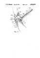
- FIG. 1is a perspective view in partial transparency of the installed probe around a vessel.
- FIG. 1ais a detail of FIG. 1 showing a single suture thread embodiment.
- FIG. 1bis a detail of the same area as FIG. 1a showing an alternative double suture embodiment.
- FIG. 2is a top view of the probe body.
- FIG. 3is a length-wise section of the probe body at lines 3--3 of FIG. 2.
- FIG. 4is a cross-section of the probe body at lines 4--4 of FIG. 2.
- FIGS. 5, 6, 7, 8 and 9show the attachment of the probe body to a vessel.
- FIG. 10shows two sizes of probes used in a patient.
- FIGS. 11a, 11b and 11cshow the probe release process.
- FIG. 12shows the extraction of the probe from the body.
- FIG. 13shows an alternative embodiment with multiple sensors in the probe.
- FIG. 1is a view of the installed probe in partial transparency.
- the probe body 10encircles the vessel 44 without overlap.
- Crystal 14is aligned to read through the entire diameter of the vessel.
- suture guides 16a, 16b, 16c, and 16dare generally parallel pairs of perforations through the probe body.
- An embodimentcan have a plurality of suture guides spaced in pairs along one end of the probe body 10. Depending on the length of probe desired to wrap around the vessel, the probe can be cut leaving suture guides at the end of the probe body to be used in the attachment process.
- a blood flow sensor Doppler transducer crystal 14is used.
- lead wires 20 and 22are shown attached to crystal 14 and extending across the top of the probe body 10 into opening 24 going inside the probe body.
- FIG. 3is a section lengthwise through the probe.
- the probe body 10is a generally rectangular body of flexible rubber sheeting which can be wrapped around a vessel.
- the rubber sheeting materialis biocompatible such as silicon rubber which is not reactive to body tissue and fluids.
- the length of the probe body 10is sized to encircle or partially encircle the vessel to be monitored. In an alternative embodiment the probe body is lengthened and cut to the appropriate size to surround the vessel to be monitored.
- the probe bodycan be reinforced with a layer of fabric 12.
- the rubber probe body 10 and the fabric reinforcement 12stretch to accompany vessel enlargement as needed.
- Other reinforcing materials similar to woven fabriccan be used.
- a generally flat piezoelectric crystal 14is embedded at the angle of about 30° to 60° sideways to the surface of the probe body that faces the vessel after attachment as further described.
- the crystal 14is typically 10 MHz or 20 MHz but any frequency can be used.
- the face of the crystal 14 which faces the vesselshas a thin coating 15 of epoxy for protection.
- On the other face of the crystal 14is a layer 13 of acoustic material such as cork for sound absorbency.
- FIG. 4shows the orientation of crystal 14 in the probe body at an angle.
- tube 18of flexible material such as silicon rubber.
- the crystal 14is embedded between the tube 18 and the suture guides 16a, 16b, 16c and 16d as shown in FIGS. 2 and 3.
- Lead wires 20 and 22are soldered one to each face of crystal 14. Other lead wire configurations may be used depending on the sensor used.
- the lead wires 20 and 22extend from crystal 14 and further extend into tube 18 through a small opening 24 near the connection of tube 18 with probe body 10.
- the lead wires 20 and 22extend through the length of tube 18 and ultimately terminate at connections for a monitoring display instrument which reads the signals from the biological sensor.
- a release cable 26extends through the tube 18.
- the release cable shownis a steel wire 28 at least partially surrounded by a wire coil 30.
- the release cable 26is flexible.
- the steel wire 28extends into the probe body 10 in a cavity 32 situated between the tube attachment to the probe body and the crystal 14.
- the steel wire 28 which extends into the cavity 32is not wrapped with the wire coil 30.
- the cavityis adjacent the tube entrance so that the steel wire 28 easily extends into the cavity. In a longer probe embodiment the crystal would be further spaced from the cavity.
- FIG. 1aThe suture used to hold the probe in place is shown in two embodiments in enlargements FIG. 1a and FIG. 1b.
- a suture 34is looped around the part of steel wire 28 which extends into the cavity 32.
- the free ends of suture 34extend outside the probe body through an opening 36 in the bottom of the probe body 10 which communicates with the cavity 32.
- An opening 31is made through the top of the probe body into the cavity near the suture 34.
- FIG. 1btwo separate sutures 33 and 35 are individually looped at one end and the loops 37 and 39 respectively are slipped over the steel wire 28 inside cavity 32.
- the free end of both suture 33 and 35extend outside the probe body in the similar manner as suture 34.
- FIG. 1ais used for the rest of the drawings although either suture embodiment may be used.
- the release cable 26is fixed at about the point of joinder of flexible tube 18 and probe body 10 near the cavity 32 by an inner layer 38 of rubber surrounding the release cable 26 and filling the internal diameter of tube 18.
- the release cable 26is positioned inside the tube 18 so that the portion of steel wire 28 with the looped suture 34 is held in place in the cavity 32.
- a seal 27 of rubber or other materialis placed between the outer wire coil 30 and the stainless steel wire 28 to prevent entrance of foreign material inside the coil.
- the cavity 32may be filled with a substance that will allow the traction of steel wire 28.
- An outer coating 41 of silicon rubbercovers the top of the probe body 10 enclosing and protecting the lead wires 20 and 22 which extend from crystal 14 into the tubing 18.
- FIGS. 5, 6, 7, 8 and 9illustrate the attachment of the probe to a vessel.
- some parts of the probeare shown in more relative transparency so that the operation can be easily viewed.
- FIG. 5the vessel to be monitored has been located and the section of the vessel 44 for probe attachment has been isolated and if necessary dissected.
- the surgeoninserts the probe body 10 under and around the vessel.
- the free ends of the suture 34terminate in curved needles 40 and 42.
- the loop of suture on steel wire 28 inside the probe body 10is shown and the free ends of the suture extend through opening 36.
- Tube 18is long enough to extend outside the patient's body through an opening in the skin.
- the two free ends of the suture 34are looped under the vessel.
- the suture needle 42is inserted through suture guides 16b and 16a and needle 40 is inserted through suture guides 16d and 16c to thread the two ends of suture 34 to the end of probe body 10.
- Suture guidesare not necessary as the suture needles can generally penetrate the flexible sheeting material of the probe body 10.
- the suturing processcan be done away from the vessel 44 enabling the surgeon to easily manipulate the probe without damage to the vessel or necessitating close work near the vessel. The installation of the probe is simplified in this manner.
- FIG. 8shows the drawing up of the sutures after threading through the suture guides.
- the suturedoes not go underneath the probe body 10 so that release will be achieved as shown in FIGS. 11a, 11b and 11c.
- the dual suture arrangement of FIG. 1bwill allow for the suture to go underneath the probe and release according to this invention.
- the probe body 10wraps around the vessel.
- the crystal 14is positioned at the vessel wall so that a sound beam travels across the lumen of the vessel approximately through the center line.
- FIG. 9shows the probe body 10 encircling the vessel after the suture has been tightened, tied and in the process of having the free ends cut.
- FIG. 1is a transparency showing the crystal 14 positioned snugly next to the vessel with the probe body suture in place around the vessel.
- the suture opening 36is spaced on the end of the probe body opposite the suture guides as shown so that when the probe is tightened, it encircles the vessel without overlap. It is possible to use a probe which partially encircles the vessel as long as the crystal is positioned properly.
- FIG. 1shows the probe as it would remain in the patient's body for a period of time.
- FIG. 10is illustrative of the use of probes in a patient and shows two sizes.
- Probe 50is a longer version monitoring the aorta.
- Probe 52is a shorter version monitoring a grafted vessel.
- the flexible tubes 54 and 56extend from the probe bodies 50 and 52 respectively and terminate in connections 58 and 60 which plug into display monitors.
- the release cablesalso extend through the terminal ends of tubes 54 and 56.
- FIGS. 11a, 11b and 11cillustrate the nonsurgical removal procedure of the probe.
- the release cable 26extends through the tube 18 as well as the lead wires 20 and 22.
- the lead wiresare fitted to a connection 62 for the display monitor (not shown).
- the end of the release cable 26is covered by a cap 64 for protection to assure that the release mechanism is not accidently actuated.
- the cap 64is removed, as shown in FIG. 11b, when the probe is to be removed from the body.
- a portion of the steel wire 28 of the release cable 26extends outside of the wire coil 30.
- the steel wire 28is tractable independently of the coil 30.
- a needle holdergrasps the end of steel wire 28 with gentle traction.
- the traction on the steel wire 28causes it to move from its position in cavity 32 securing the looped suture 34.
- With the movement of steel wire 28 from inside cavity 32the suture is released from the probe body.
- the probecan unwind from around the vessel.
- the releaseis shown in FIG. 11c. Generally when the probe is released the output from the biological sensor will cease or change due to a change in position of the probe.
- the probeis then extracted.
- the tube 18can be pulled gently and the device removed without surgery through the opening in the skin through which the tube extended.
- the probecan be extracted at any time with the release device of this invention.
- FIG. 13is an alternative embodiment showing multiple crystals embedded in a probe body.
- probe body 102is shown encircling vessel 104.
- Biological sensors 106, 108 and 110are shown in transparency in probe body 102 spaced between the terminal end of the probe body and flexible tubing 118 extending from the probe body 102. With the exception of the multiple sensors the probe body 102 and suturing and tractable release members are as described above for FIGS. 1-12.
- the sensors 106, 108, and 110are shown with associated pairs of lead wires 112 and 112a, 114 and 114a, and 116 and 116a, respectively.
- the lead wiresextend from the sensors through flexible tube 118.
- the probeis shown in the sutured state with suture 120 wrapped around steel wire 122.
- Cable 124encloses the steel wire 122 past the suture and extends through the flexible tubing 118.
- the implantation and release methodsare the same as described above.
- the multiple sensor embodimentcan be utilized in a variety of circumstances. More than one type of biological sensor can be placed in the probe. In the case of Doppler transducers, more than one crystal in the probe can provide increased assurance of correct orientation by one or more of the crystals for accurate flow measurements. Multiple crystals also are protection in case of malfunction of one crystal. Multiple crystals give more than one sampling of data for comparison purposes.
- a multiple crystal probeis preferable to give a profile of nonsymmetric flow.
- the sensorscan be run in sequence or simultaneously as desired. Other uses of the single and multiple sensor probe are evident from this disclosure.
- the claimed inventionis intended to include all uses.
Landscapes
- Health & Medical Sciences (AREA)
- Life Sciences & Earth Sciences (AREA)
- Surgery (AREA)
- Veterinary Medicine (AREA)
- Animal Behavior & Ethology (AREA)
- Public Health (AREA)
- Engineering & Computer Science (AREA)
- Biomedical Technology (AREA)
- Heart & Thoracic Surgery (AREA)
- Medical Informatics (AREA)
- Molecular Biology (AREA)
- General Health & Medical Sciences (AREA)
- Biophysics (AREA)
- Physics & Mathematics (AREA)
- Pathology (AREA)
- Nuclear Medicine, Radiotherapy & Molecular Imaging (AREA)
- Radiology & Medical Imaging (AREA)
- Vascular Medicine (AREA)
- Hematology (AREA)
- Ultra Sonic Daignosis Equipment (AREA)
Abstract
Description
Claims (13)
Priority Applications (2)
| Application Number | Priority Date | Filing Date | Title |
|---|---|---|---|
| US07/199,163US4926875A (en) | 1988-01-25 | 1988-05-26 | Implantable and extractable biological sensor probe |
| AU29432/89AAU617755B2 (en) | 1988-01-25 | 1989-01-18 | Implantable and extractable biological sensor probe |
Applications Claiming Priority (2)
| Application Number | Priority Date | Filing Date | Title |
|---|---|---|---|
| US14736888A | 1988-01-25 | 1988-01-25 | |
| US07/199,163US4926875A (en) | 1988-01-25 | 1988-05-26 | Implantable and extractable biological sensor probe |
Related Parent Applications (1)
| Application Number | Title | Priority Date | Filing Date |
|---|---|---|---|
| US14736888AContinuation-In-Part | 1988-01-25 | 1988-01-25 |
Publications (1)
| Publication Number | Publication Date |
|---|---|
| US4926875Atrue US4926875A (en) | 1990-05-22 |
Family
ID=26844861
Family Applications (1)
| Application Number | Title | Priority Date | Filing Date |
|---|---|---|---|
| US07/199,163Expired - Fee RelatedUS4926875A (en) | 1988-01-25 | 1988-05-26 | Implantable and extractable biological sensor probe |
Country Status (1)
| Country | Link |
|---|---|
| US (1) | US4926875A (en) |
Cited By (64)
| Publication number | Priority date | Publication date | Assignee | Title |
|---|---|---|---|---|
| US5152293A (en)* | 1991-07-01 | 1992-10-06 | Northwestern University | Finger-mounted intraoperative imaging device |
| WO1992021284A1 (en)* | 1991-06-03 | 1992-12-10 | Applied Biometrics, Inc. | Removable implanted device |
| US5247938A (en)* | 1990-01-11 | 1993-09-28 | University Of Washington | Method and apparatus for determining the motility of a region in the human body |
| US5289821A (en)* | 1993-06-30 | 1994-03-01 | Swartz William M | Method of ultrasonic Doppler monitoring of blood flow in a blood vessel |
| US5390679A (en)* | 1993-06-03 | 1995-02-21 | Eli Lilly And Company | Continuous cardiac output derived from the arterial pressure waveform using pattern recognition |
| US5487756A (en)* | 1994-12-23 | 1996-01-30 | Simon Fraser University | Implantable cuff having improved closure |
| US5588436A (en)* | 1995-10-11 | 1996-12-31 | Cook Pacemaker Corporation | Pulsed doppler probe |
| US5807258A (en)* | 1997-10-14 | 1998-09-15 | Cimochowski; George E. | Ultrasonic sensors for monitoring the condition of a vascular graft |
| US5916171A (en)* | 1994-05-31 | 1999-06-29 | Mayevsky; Avraham | Tissue monitor |
| JP3207235B2 (en) | 1992-03-09 | 2001-09-10 | アロカ株式会社 | Ultrasound probe for blood flow measurement |
| WO2001078588A1 (en)* | 2000-04-14 | 2001-10-25 | Diametrics Medical Limited | Insertion of sensors into soft tissue |
| WO2001065537A3 (en)* | 2000-03-02 | 2002-05-16 | Mayo Foundation | Apparatus and method of holding and manipulating small ultrasound transducers |
| US6398734B1 (en)* | 1997-10-14 | 2002-06-04 | Vascusense, Inc. | Ultrasonic sensors for monitoring the condition of flow through a cardiac valve |
| WO2002048656A3 (en)* | 2000-12-12 | 2002-09-06 | Data Sciences Int Inc | Adjustable flow probe |
| US6697667B1 (en) | 2001-05-31 | 2004-02-24 | Advanced Cardiovascular Systems, Inc. | Apparatus and method for locating coronary sinus |
| US20040059396A1 (en)* | 2002-09-25 | 2004-03-25 | Reinke James D. | Implantable medical device communication system |
| US6716178B1 (en) | 2001-05-31 | 2004-04-06 | Advanced Cardiovascular Systems, Inc. | Apparatus and method for performing thermal and laser doppler velocimetry measurements |
| US20040122490A1 (en)* | 2002-09-25 | 2004-06-24 | Medtronic, Inc. | Implantable medical device communication system with pulsed power biasing |
| EP1077644A4 (en)* | 1998-03-23 | 2004-07-07 | Tobo Llc | Device for insertion of a sensor |
| US20050159801A1 (en)* | 2004-01-16 | 2005-07-21 | Medtronic, Inc. | Novel implantable lead including sensor |
| US20060241446A1 (en)* | 2005-03-04 | 2006-10-26 | White Chris A | Method for synchronization of breathing signal with the capture of ultrasound data |
| DE102005035022A1 (en)* | 2005-05-19 | 2006-11-23 | Universitätsklinikum Freiburg | Implantable blood pressure sensor |
| US20070021790A1 (en)* | 2000-09-27 | 2007-01-25 | Cvrx, Inc. | Automatic baroreflex modulation responsive to adverse event |
| US20070038259A1 (en)* | 2000-09-27 | 2007-02-15 | Cvrx, Inc. | Method and apparatus for stimulation of baroreceptors in pulmonary artery |
| US7286884B2 (en) | 2004-01-16 | 2007-10-23 | Medtronic, Inc. | Implantable lead including sensor |
| US20070282209A1 (en)* | 2006-06-02 | 2007-12-06 | Cook Vascular Incorporated | Adjustable tension cuff assembly |
| US20080021325A1 (en)* | 2006-06-12 | 2008-01-24 | Drost Cornelis J | System and method of perivascular pressure and flow measurement |
| US7329223B1 (en) | 2001-05-31 | 2008-02-12 | Abbott Cardiovascular Systems Inc. | Catheter with optical fiber sensor |
| US20080172116A1 (en)* | 2007-01-16 | 2008-07-17 | Ndi Medical, Inc. | Devices, systems, and methods employing a molded nerve cuff electrode |
| US20080177364A1 (en)* | 2000-09-27 | 2008-07-24 | Cvrx, Inc. | Self-locking electrode assembly usable with an implantable medical device |
| US20080200938A1 (en)* | 2007-02-15 | 2008-08-21 | Cook Vascular Incorporated | Probe coupler assembly |
| US20080208065A1 (en)* | 2007-02-20 | 2008-08-28 | University Of Louisville Research Foundation | Perivascular pressure sensor and sensing system |
| US20090069738A1 (en)* | 2005-12-29 | 2009-03-12 | Cvrx, Inc. | Electrode Structures Having Anti-Inflammatory Properties And Methods Of Use |
| US7532920B1 (en) | 2001-05-31 | 2009-05-12 | Advanced Cardiovascular Systems, Inc. | Guidewire with optical fiber |
| EP1565104A4 (en)* | 2002-10-24 | 2010-05-05 | Synovis Life Technologies Inc | Device and method for vascular monitoring |
| US7761167B2 (en) | 2004-06-10 | 2010-07-20 | Medtronic Urinary Solutions, Inc. | Systems and methods for clinician control of stimulation systems |
| US20100222851A1 (en)* | 2002-04-08 | 2010-09-02 | Ardian, Inc. | Methods for monitoring renal neuromodulation |
| US7797058B2 (en) | 2004-08-04 | 2010-09-14 | Ndi Medical, Llc | Devices, systems, and methods employing a molded nerve cuff electrode |
| US7813809B2 (en) | 2004-06-10 | 2010-10-12 | Medtronic, Inc. | Implantable pulse generator for providing functional and/or therapeutic stimulation of muscles and/or nerves and/or central nervous system tissue |
| DE102009017797A1 (en)* | 2009-04-20 | 2010-10-21 | Albert-Ludwig-Universität Freiburg | Implantable device i.e. reflective photoplethysmograph sensor, for extravascular detection of blood pressure of patient, has light absorbing optical barrier provided between solid body light source and solid body photodetector |
| US7949400B2 (en) | 2000-09-27 | 2011-05-24 | Cvrx, Inc. | Devices and methods for cardiovascular reflex control via coupled electrodes |
| US20110190850A1 (en)* | 2010-01-29 | 2011-08-04 | Medtronic, Inc. | Clock synchronization in an implantable medical device system |
| US8165692B2 (en) | 2004-06-10 | 2012-04-24 | Medtronic Urinary Solutions, Inc. | Implantable pulse generator power management |
| US8195304B2 (en) | 2004-06-10 | 2012-06-05 | Medtronic Urinary Solutions, Inc. | Implantable systems and methods for acquisition and processing of electrical signals |
| US8264129B2 (en) | 2010-07-21 | 2012-09-11 | General Electric Company | Device and system for measuring material thickness |
| US8467875B2 (en) | 2004-02-12 | 2013-06-18 | Medtronic, Inc. | Stimulation of dorsal genital nerves to treat urologic dysfunctions |
| US8606359B2 (en) | 2000-09-27 | 2013-12-10 | Cvrx, Inc. | System and method for sustained baroreflex stimulation |
| US8680745B2 (en) | 2010-07-21 | 2014-03-25 | General Electric Company | Device for measuring material thickness |
| US8801623B2 (en) | 2010-01-14 | 2014-08-12 | Koninklijke Philips N.V. | Sensor determining a physical or physiological parameter |
| US8857261B2 (en) | 2012-04-12 | 2014-10-14 | General Electric Company | Sensing device and method of attaching the same |
| US9205255B2 (en) | 2004-06-10 | 2015-12-08 | Medtronic Urinary Solutions, Inc. | Implantable pulse generator systems and methods for providing functional and/or therapeutic stimulation of muscles and/or nerves and/or central nervous system tissue |
| US9308382B2 (en) | 2004-06-10 | 2016-04-12 | Medtronic Urinary Solutions, Inc. | Implantable pulse generator systems and methods for providing functional and/or therapeutic stimulation of muscles and/or nerves and/or central nervous system tissue |
| US9480846B2 (en) | 2006-05-17 | 2016-11-01 | Medtronic Urinary Solutions, Inc. | Systems and methods for patient control of stimulation systems |
| WO2018220143A1 (en)* | 2017-05-31 | 2018-12-06 | Foundry Innovation And Research 1, Ltd | Implantable ultrasonic vascular sensor |
| EP3581094A1 (en)* | 2018-06-14 | 2019-12-18 | Ceské vysoké ucení technické v Praze | A system for attaching a measuring probe to provide monitoring of transplanted organs |
| EP3581097A1 (en) | 2018-06-14 | 2019-12-18 | Ceské vysoké ucení technické v Praze | A mechanical system for attaching a measuring probe to provide monitoring of transplanted organs |
| US10806428B2 (en) | 2015-02-12 | 2020-10-20 | Foundry Innovation & Research 1, Ltd. | Implantable devices and related methods for heart failure monitoring |
| US10806352B2 (en) | 2016-11-29 | 2020-10-20 | Foundry Innovation & Research 1, Ltd. | Wireless vascular monitoring implants |
| US11039813B2 (en) | 2015-08-03 | 2021-06-22 | Foundry Innovation & Research 1, Ltd. | Devices and methods for measurement of Vena Cava dimensions, pressure and oxygen saturation |
| US11206992B2 (en) | 2016-08-11 | 2021-12-28 | Foundry Innovation & Research 1, Ltd. | Wireless resonant circuit and variable inductance vascular monitoring implants and anchoring structures therefore |
| US11564596B2 (en) | 2016-08-11 | 2023-01-31 | Foundry Innovation & Research 1, Ltd. | Systems and methods for patient fluid management |
| US11701018B2 (en) | 2016-08-11 | 2023-07-18 | Foundry Innovation & Research 1, Ltd. | Wireless resonant circuit and variable inductance vascular monitoring implants and anchoring structures therefore |
| US11779238B2 (en) | 2017-05-31 | 2023-10-10 | Foundry Innovation & Research 1, Ltd. | Implantable sensors for vascular monitoring |
| US12376818B2 (en)* | 2022-06-23 | 2025-08-05 | Coopersurgical, Inc. | Doppler probes, blood flow monitoring systems, and methods of monitoring blood flow |
Citations (12)
| Publication number | Priority date | Publication date | Assignee | Title |
|---|---|---|---|---|
| US3124132A (en)* | 1964-03-10 | Dynamic fluid pressure transducer | ||
| US3605726A (en)* | 1969-04-14 | 1971-09-20 | Bryn T Williams | Flexible,extra vascular electromagnetic blood flow probe |
| US3661146A (en)* | 1968-12-31 | 1972-05-09 | Comp Generale Electricite | Transducer arrangement for measuring blood flow |
| US3921622A (en)* | 1973-02-27 | 1975-11-25 | Edward Michael Cole | Method and apparatus for ultrasonic detection of inclusions in a flowing fluid |
| US3955560A (en)* | 1974-06-10 | 1976-05-11 | Stein Richard B | Implantable neural electrode |
| US3977247A (en)* | 1974-12-23 | 1976-08-31 | Siemens Aktiengesellschaft | Arrangement for the measurement of the flow volume of flowing media |
| US4313443A (en)* | 1980-09-11 | 1982-02-02 | Nasa | Pocket ECG electrode |
| US4355643A (en)* | 1980-03-05 | 1982-10-26 | University Of Iowa Research Foundation | Vacuum cup doppler flow transducer and method for using same |
| US4419999A (en)* | 1981-04-17 | 1983-12-13 | May Jr James W | Method and apparatus for monitoring vascular flow |
| US4442844A (en)* | 1981-08-28 | 1984-04-17 | Navach Joseph H | Method and apparatus for making physiological measurements |
| US4541433A (en)* | 1984-06-01 | 1985-09-17 | Medtronic, Inc. | Cardiac output monitor |
| US4602624A (en)* | 1984-10-11 | 1986-07-29 | Case Western Reserve University | Implantable cuff, method of manufacture, and method of installation |
- 1988
- 1988-05-26USUS07/199,163patent/US4926875A/ennot_activeExpired - Fee Related
Patent Citations (12)
| Publication number | Priority date | Publication date | Assignee | Title |
|---|---|---|---|---|
| US3124132A (en)* | 1964-03-10 | Dynamic fluid pressure transducer | ||
| US3661146A (en)* | 1968-12-31 | 1972-05-09 | Comp Generale Electricite | Transducer arrangement for measuring blood flow |
| US3605726A (en)* | 1969-04-14 | 1971-09-20 | Bryn T Williams | Flexible,extra vascular electromagnetic blood flow probe |
| US3921622A (en)* | 1973-02-27 | 1975-11-25 | Edward Michael Cole | Method and apparatus for ultrasonic detection of inclusions in a flowing fluid |
| US3955560A (en)* | 1974-06-10 | 1976-05-11 | Stein Richard B | Implantable neural electrode |
| US3977247A (en)* | 1974-12-23 | 1976-08-31 | Siemens Aktiengesellschaft | Arrangement for the measurement of the flow volume of flowing media |
| US4355643A (en)* | 1980-03-05 | 1982-10-26 | University Of Iowa Research Foundation | Vacuum cup doppler flow transducer and method for using same |
| US4313443A (en)* | 1980-09-11 | 1982-02-02 | Nasa | Pocket ECG electrode |
| US4419999A (en)* | 1981-04-17 | 1983-12-13 | May Jr James W | Method and apparatus for monitoring vascular flow |
| US4442844A (en)* | 1981-08-28 | 1984-04-17 | Navach Joseph H | Method and apparatus for making physiological measurements |
| US4541433A (en)* | 1984-06-01 | 1985-09-17 | Medtronic, Inc. | Cardiac output monitor |
| US4602624A (en)* | 1984-10-11 | 1986-07-29 | Case Western Reserve University | Implantable cuff, method of manufacture, and method of installation |
Non-Patent Citations (12)
| Title |
|---|
| Derwent s Abst. No. 80 A1750 D/02, SU 733643.* |
| Derwent s Abst. No. 81 G8361 E/23, SU 856437.* |
| Derwent's Abst. No. 80-A1750 D/02, SU 733643. |
| Derwent's Abst. No. 81-G8361 E/23, SU 856437. |
| Keagy et al., "Constant Postoperative Monitoring of Cardiac Output after Correction of Congenital Heart Defects", J. Thorac. Cardiovasc. Surg., 1987;93;658-64. |
| Keagy et al., Constant Postoperative Monitoring of Cardiac Output after Correction of Congenital Heart Defects , J. Thorac. Cardiovasc. Surg., 1987;93;658 64.* |
| Matre et al., "Continuous Measurement of Aortic Blood Velocity, after Cardiac Surgery, by Means of an Extractable Doppler Ultrasound Probe", J. Biomec. Eng., vol. 4, 1985, pp. 84-88. |
| Matre et al., Continuous Measurement of Aortic Blood Velocity, after Cardiac Surgery, by Means of an Extractable Doppler Ultrasound Probe , J. Biomec. Eng., vol. 4, 1985, pp. 84 88.* |
| Payen et al., "Comparison of Perioperative and Postoperative Phasic Blood Flow in Aortocoronary Bypass Grafts by Means of Pulsed Doppler Echocardiography with Implantable Microprobes", Coronary Artery Surgery, vol. 74, (Suppl. III), Nov. 1986, 111-61-111-67. |
| Payen et al., Comparison of Perioperative and Postoperative Phasic Blood Flow in Aortocoronary Bypass Grafts by Means of Pulsed Doppler Echocardiography with Implantable Microprobes , Coronary Artery Surgery, vol. 74, (Suppl. III), Nov. 1986, 111 61 111 67.* |
| Svennevig et al., "Continuous Monitoring of Cardiac Output Postoperatively Using an Implantable Doppler Probe", Scand. J. Cardiovasc. Surg., 20:145-149, 1986. |
| Svennevig et al., Continuous Monitoring of Cardiac Output Postoperatively Using an Implantable Doppler Probe , Scand. J. Cardiovasc. Surg., 20:145 149, 1986.* |
Cited By (116)
| Publication number | Priority date | Publication date | Assignee | Title |
|---|---|---|---|---|
| US5247938A (en)* | 1990-01-11 | 1993-09-28 | University Of Washington | Method and apparatus for determining the motility of a region in the human body |
| WO1992021284A1 (en)* | 1991-06-03 | 1992-12-10 | Applied Biometrics, Inc. | Removable implanted device |
| US5205292A (en)* | 1991-06-03 | 1993-04-27 | Applied Biometric, Inc. | Removable implanted device |
| WO1993000858A1 (en)* | 1991-07-01 | 1993-01-21 | Northwestern University | Finger-mounted intraoperative imaging device |
| US5152293A (en)* | 1991-07-01 | 1992-10-06 | Northwestern University | Finger-mounted intraoperative imaging device |
| JP3207235B2 (en) | 1992-03-09 | 2001-09-10 | アロカ株式会社 | Ultrasound probe for blood flow measurement |
| US5390679A (en)* | 1993-06-03 | 1995-02-21 | Eli Lilly And Company | Continuous cardiac output derived from the arterial pressure waveform using pattern recognition |
| US5797395A (en)* | 1993-06-03 | 1998-08-25 | Eli Lilly And Company | Continuous cardiac output derived from arterial pressure waveform using pattern recognition |
| US5289821A (en)* | 1993-06-30 | 1994-03-01 | Swartz William M | Method of ultrasonic Doppler monitoring of blood flow in a blood vessel |
| US5916171A (en)* | 1994-05-31 | 1999-06-29 | Mayevsky; Avraham | Tissue monitor |
| US5487756A (en)* | 1994-12-23 | 1996-01-30 | Simon Fraser University | Implantable cuff having improved closure |
| US5588436A (en)* | 1995-10-11 | 1996-12-31 | Cook Pacemaker Corporation | Pulsed doppler probe |
| US5807258A (en)* | 1997-10-14 | 1998-09-15 | Cimochowski; George E. | Ultrasonic sensors for monitoring the condition of a vascular graft |
| US5967989A (en)* | 1997-10-14 | 1999-10-19 | Vascusense, Inc. | Ultrasonic sensors for monitoring the condition of a vascular graft |
| EP1026984A4 (en)* | 1997-10-14 | 2002-03-27 | Vascusense Inc | Ultrasonic sensors for monitoring the condition of a vascular graft |
| US6398734B1 (en)* | 1997-10-14 | 2002-06-04 | Vascusense, Inc. | Ultrasonic sensors for monitoring the condition of flow through a cardiac valve |
| EP1077644A4 (en)* | 1998-03-23 | 2004-07-07 | Tobo Llc | Device for insertion of a sensor |
| EP1210012A4 (en)* | 1999-08-12 | 2008-11-26 | Cardiometrix Inc | Ultrasonic monitoring of cardiac valvular flow condition |
| WO2001065537A3 (en)* | 2000-03-02 | 2002-05-16 | Mayo Foundation | Apparatus and method of holding and manipulating small ultrasound transducers |
| US6485425B2 (en) | 2000-03-02 | 2002-11-26 | Mayo Foundation For Medical Education And Research | Apparatus and method of holding and manipulating small ultrasound transducers |
| WO2001078588A1 (en)* | 2000-04-14 | 2001-10-25 | Diametrics Medical Limited | Insertion of sensors into soft tissue |
| US8583236B2 (en) | 2000-09-27 | 2013-11-12 | Cvrx, Inc. | Devices and methods for cardiovascular reflex control |
| US20070038259A1 (en)* | 2000-09-27 | 2007-02-15 | Cvrx, Inc. | Method and apparatus for stimulation of baroreceptors in pulmonary artery |
| US8086314B1 (en) | 2000-09-27 | 2011-12-27 | Cvrx, Inc. | Devices and methods for cardiovascular reflex control |
| US20100222831A1 (en)* | 2000-09-27 | 2010-09-02 | Bolea Stephen L | Electrode structures and methods for their use in cardiovascular reflex control |
| US9044609B2 (en) | 2000-09-27 | 2015-06-02 | Cvrx, Inc. | Electrode structures and methods for their use in cardiovascular reflex control |
| US20080177364A1 (en)* | 2000-09-27 | 2008-07-24 | Cvrx, Inc. | Self-locking electrode assembly usable with an implantable medical device |
| US8880190B2 (en) | 2000-09-27 | 2014-11-04 | Cvrx, Inc. | Electrode structures and methods for their use in cardiovascular reflex control |
| US8838246B2 (en) | 2000-09-27 | 2014-09-16 | Cvrx, Inc. | Devices and methods for cardiovascular reflex treatments |
| US8060206B2 (en) | 2000-09-27 | 2011-11-15 | Cvrx, Inc. | Baroreflex modulation to gradually decrease blood pressure |
| US7949400B2 (en) | 2000-09-27 | 2011-05-24 | Cvrx, Inc. | Devices and methods for cardiovascular reflex control via coupled electrodes |
| US8718789B2 (en) | 2000-09-27 | 2014-05-06 | Cvrx, Inc. | Electrode structures and methods for their use in cardiovascular reflex control |
| US8712531B2 (en) | 2000-09-27 | 2014-04-29 | Cvrx, Inc. | Automatic baroreflex modulation responsive to adverse event |
| US20070021790A1 (en)* | 2000-09-27 | 2007-01-25 | Cvrx, Inc. | Automatic baroreflex modulation responsive to adverse event |
| US20080177350A1 (en)* | 2000-09-27 | 2008-07-24 | Cvrx, Inc. | Expandable Stimulation Electrode with Integrated Pressure Sensor and Methods Related Thereto |
| US8606359B2 (en) | 2000-09-27 | 2013-12-10 | Cvrx, Inc. | System and method for sustained baroreflex stimulation |
| US9427583B2 (en) | 2000-09-27 | 2016-08-30 | Cvrx, Inc. | Electrode structures and methods for their use in cardiovascular reflex control |
| US8290595B2 (en) | 2000-09-27 | 2012-10-16 | Cvrx, Inc. | Method and apparatus for stimulation of baroreceptors in pulmonary artery |
| WO2002048656A3 (en)* | 2000-12-12 | 2002-09-06 | Data Sciences Int Inc | Adjustable flow probe |
| US6709430B2 (en) | 2000-12-12 | 2004-03-23 | Transoma Medical, Inc. | Adjustable flow probe |
| US20040064049A1 (en)* | 2000-12-12 | 2004-04-01 | Transoma Medical, Inc. | Adjustable flow probe |
| US7783338B2 (en) | 2001-05-31 | 2010-08-24 | Advanced Cardiovascular Systems, Inc. | Catheter with optical fiber sensor |
| US20080139897A1 (en)* | 2001-05-31 | 2008-06-12 | Ainsworth Robert D | Catheter with optical fiber sensor |
| US7329223B1 (en) | 2001-05-31 | 2008-02-12 | Abbott Cardiovascular Systems Inc. | Catheter with optical fiber sensor |
| US6697667B1 (en) | 2001-05-31 | 2004-02-24 | Advanced Cardiovascular Systems, Inc. | Apparatus and method for locating coronary sinus |
| US6716178B1 (en) | 2001-05-31 | 2004-04-06 | Advanced Cardiovascular Systems, Inc. | Apparatus and method for performing thermal and laser doppler velocimetry measurements |
| US7532920B1 (en) | 2001-05-31 | 2009-05-12 | Advanced Cardiovascular Systems, Inc. | Guidewire with optical fiber |
| US20090228065A1 (en)* | 2001-09-26 | 2009-09-10 | Cvrx, Inc. | Implantable vascular structures and methods for their use |
| US8768470B2 (en)* | 2002-04-08 | 2014-07-01 | Medtronic Ardian Luxembourg S.A.R.L. | Methods for monitoring renal neuromodulation |
| US20100222851A1 (en)* | 2002-04-08 | 2010-09-02 | Ardian, Inc. | Methods for monitoring renal neuromodulation |
| US7139613B2 (en) | 2002-09-25 | 2006-11-21 | Medtronic, Inc. | Implantable medical device communication system with pulsed power biasing |
| US20040059396A1 (en)* | 2002-09-25 | 2004-03-25 | Reinke James D. | Implantable medical device communication system |
| US20040122490A1 (en)* | 2002-09-25 | 2004-06-24 | Medtronic, Inc. | Implantable medical device communication system with pulsed power biasing |
| US7013178B2 (en) | 2002-09-25 | 2006-03-14 | Medtronic, Inc. | Implantable medical device communication system |
| EP1565104A4 (en)* | 2002-10-24 | 2010-05-05 | Synovis Life Technologies Inc | Device and method for vascular monitoring |
| US8103357B2 (en) | 2004-01-16 | 2012-01-24 | Medtronic, Inc. | Implantable lead including sensor |
| US20050159801A1 (en)* | 2004-01-16 | 2005-07-21 | Medtronic, Inc. | Novel implantable lead including sensor |
| US7286884B2 (en) | 2004-01-16 | 2007-10-23 | Medtronic, Inc. | Implantable lead including sensor |
| US8467875B2 (en) | 2004-02-12 | 2013-06-18 | Medtronic, Inc. | Stimulation of dorsal genital nerves to treat urologic dysfunctions |
| US10434320B2 (en) | 2004-06-10 | 2019-10-08 | Medtronic Urinary Solutions, Inc. | Implantable pulse generator systems and methods for providing functional and/or therapeutic stimulation of muscles and/or nerves and/or central nervous system tissue |
| US9724526B2 (en) | 2004-06-10 | 2017-08-08 | Medtronic Urinary Solutions, Inc. | Implantable pulse generator systems and methods for operating the same |
| US9205255B2 (en) | 2004-06-10 | 2015-12-08 | Medtronic Urinary Solutions, Inc. | Implantable pulse generator systems and methods for providing functional and/or therapeutic stimulation of muscles and/or nerves and/or central nervous system tissue |
| US7761167B2 (en) | 2004-06-10 | 2010-07-20 | Medtronic Urinary Solutions, Inc. | Systems and methods for clinician control of stimulation systems |
| US9308382B2 (en) | 2004-06-10 | 2016-04-12 | Medtronic Urinary Solutions, Inc. | Implantable pulse generator systems and methods for providing functional and/or therapeutic stimulation of muscles and/or nerves and/or central nervous system tissue |
| US8706252B2 (en) | 2004-06-10 | 2014-04-22 | Medtronic, Inc. | Systems and methods for clinician control of stimulation system |
| US7813809B2 (en) | 2004-06-10 | 2010-10-12 | Medtronic, Inc. | Implantable pulse generator for providing functional and/or therapeutic stimulation of muscles and/or nerves and/or central nervous system tissue |
| US9216294B2 (en) | 2004-06-10 | 2015-12-22 | Medtronic Urinary Solutions, Inc. | Systems and methods for clinician control of stimulation systems |
| US8165692B2 (en) | 2004-06-10 | 2012-04-24 | Medtronic Urinary Solutions, Inc. | Implantable pulse generator power management |
| US8195304B2 (en) | 2004-06-10 | 2012-06-05 | Medtronic Urinary Solutions, Inc. | Implantable systems and methods for acquisition and processing of electrical signals |
| US10293168B2 (en) | 2004-06-10 | 2019-05-21 | Medtronic Urinary Solutions, Inc. | Systems and methods for clinician control of stimulation systems |
| US7797058B2 (en) | 2004-08-04 | 2010-09-14 | Ndi Medical, Llc | Devices, systems, and methods employing a molded nerve cuff electrode |
| US20100298920A1 (en)* | 2004-08-04 | 2010-11-25 | Ndi Medical, Llc | Devices, Systems, and methods employing a molded nerve cuff electrode |
| US7798963B2 (en) | 2005-03-04 | 2010-09-21 | Visualsonics Inc. | Method for synchronization of breathing signal with the capture of ultrasound data |
| US20060241446A1 (en)* | 2005-03-04 | 2006-10-26 | White Chris A | Method for synchronization of breathing signal with the capture of ultrasound data |
| US20110054321A1 (en)* | 2005-03-04 | 2011-03-03 | Visualsonics Inc. | Method for synchronization of breathing signal with the capture of ultrasound data |
| WO2006122750A1 (en)* | 2005-05-19 | 2006-11-23 | Universitätsklinikum Freiburg | Implantable blood pressure sensor |
| DE102005035022A1 (en)* | 2005-05-19 | 2006-11-23 | Universitätsklinikum Freiburg | Implantable blood pressure sensor |
| US20090069738A1 (en)* | 2005-12-29 | 2009-03-12 | Cvrx, Inc. | Electrode Structures Having Anti-Inflammatory Properties And Methods Of Use |
| US9480846B2 (en) | 2006-05-17 | 2016-11-01 | Medtronic Urinary Solutions, Inc. | Systems and methods for patient control of stimulation systems |
| US10322287B2 (en) | 2006-05-17 | 2019-06-18 | Medtronic Urinary Solutions, Inc. | Systems and methods for patient control of stimulation systems |
| US7468039B2 (en)* | 2006-06-02 | 2008-12-23 | Cook Vascular Incorporated | Adjustable tension cuff assembly |
| US20070282209A1 (en)* | 2006-06-02 | 2007-12-06 | Cook Vascular Incorporated | Adjustable tension cuff assembly |
| US20080021325A1 (en)* | 2006-06-12 | 2008-01-24 | Drost Cornelis J | System and method of perivascular pressure and flow measurement |
| US8968204B2 (en)* | 2006-06-12 | 2015-03-03 | Transonic Systems, Inc. | System and method of perivascular pressure and flow measurement |
| US7996092B2 (en) | 2007-01-16 | 2011-08-09 | Ndi Medical, Inc. | Devices, systems, and methods employing a molded nerve cuff electrode |
| US20080172116A1 (en)* | 2007-01-16 | 2008-07-17 | Ndi Medical, Inc. | Devices, systems, and methods employing a molded nerve cuff electrode |
| US20120253368A1 (en)* | 2007-02-15 | 2012-10-04 | Cook Medical Technologies Llc | Probe coupler assembly |
| US8202284B2 (en)* | 2007-02-15 | 2012-06-19 | Cook Medical Technologies Llc | Probe coupler assembly |
| US20080200938A1 (en)* | 2007-02-15 | 2008-08-21 | Cook Vascular Incorporated | Probe coupler assembly |
| US8617191B2 (en)* | 2007-02-15 | 2013-12-31 | Cook Medical Technologies Llc | Probe coupler assembly |
| US8231538B2 (en) | 2007-02-20 | 2012-07-31 | University Of Louisville Research Foundation, Inc. | Perivascular pressure sensor and sensing system |
| US20080208065A1 (en)* | 2007-02-20 | 2008-08-28 | University Of Louisville Research Foundation | Perivascular pressure sensor and sensing system |
| DE102009017797A1 (en)* | 2009-04-20 | 2010-10-21 | Albert-Ludwig-Universität Freiburg | Implantable device i.e. reflective photoplethysmograph sensor, for extravascular detection of blood pressure of patient, has light absorbing optical barrier provided between solid body light source and solid body photodetector |
| US8801623B2 (en) | 2010-01-14 | 2014-08-12 | Koninklijke Philips N.V. | Sensor determining a physical or physiological parameter |
| US20110190850A1 (en)* | 2010-01-29 | 2011-08-04 | Medtronic, Inc. | Clock synchronization in an implantable medical device system |
| US8504165B2 (en) | 2010-01-29 | 2013-08-06 | Medtronic, Inc. | Clock synchronization in an implantable medical device system |
| US8396563B2 (en) | 2010-01-29 | 2013-03-12 | Medtronic, Inc. | Clock synchronization in an implantable medical device system |
| US8680745B2 (en) | 2010-07-21 | 2014-03-25 | General Electric Company | Device for measuring material thickness |
| US8264129B2 (en) | 2010-07-21 | 2012-09-11 | General Electric Company | Device and system for measuring material thickness |
| US8857261B2 (en) | 2012-04-12 | 2014-10-14 | General Electric Company | Sensing device and method of attaching the same |
| US10806428B2 (en) | 2015-02-12 | 2020-10-20 | Foundry Innovation & Research 1, Ltd. | Implantable devices and related methods for heart failure monitoring |
| US10905393B2 (en) | 2015-02-12 | 2021-02-02 | Foundry Innovation & Research 1, Ltd. | Implantable devices and related methods for heart failure monitoring |
| US11039813B2 (en) | 2015-08-03 | 2021-06-22 | Foundry Innovation & Research 1, Ltd. | Devices and methods for measurement of Vena Cava dimensions, pressure and oxygen saturation |
| US11701018B2 (en) | 2016-08-11 | 2023-07-18 | Foundry Innovation & Research 1, Ltd. | Wireless resonant circuit and variable inductance vascular monitoring implants and anchoring structures therefore |
| US11206992B2 (en) | 2016-08-11 | 2021-12-28 | Foundry Innovation & Research 1, Ltd. | Wireless resonant circuit and variable inductance vascular monitoring implants and anchoring structures therefore |
| US11419513B2 (en) | 2016-08-11 | 2022-08-23 | Foundry Innovation & Research 1, Ltd. | Wireless resonant circuit and variable inductance vascular monitoring implants and anchoring structures therefore |
| US11564596B2 (en) | 2016-08-11 | 2023-01-31 | Foundry Innovation & Research 1, Ltd. | Systems and methods for patient fluid management |
| US12268493B2 (en) | 2016-08-11 | 2025-04-08 | Foundry Innovation & Research 1, Ltd. | Systems and methods for self-directed patient fluid management |
| US12310707B2 (en) | 2016-08-11 | 2025-05-27 | Foundry Innovation & Research 1, Ltd. | Wireless resonant circuit and variable inductance vascular monitoring implants and anchoring structures therefore |
| US10806352B2 (en) | 2016-11-29 | 2020-10-20 | Foundry Innovation & Research 1, Ltd. | Wireless vascular monitoring implants |
| WO2018220143A1 (en)* | 2017-05-31 | 2018-12-06 | Foundry Innovation And Research 1, Ltd | Implantable ultrasonic vascular sensor |
| US11779238B2 (en) | 2017-05-31 | 2023-10-10 | Foundry Innovation & Research 1, Ltd. | Implantable sensors for vascular monitoring |
| US11944495B2 (en) | 2017-05-31 | 2024-04-02 | Foundry Innovation & Research 1, Ltd. | Implantable ultrasonic vascular sensor |
| EP3581097A1 (en) | 2018-06-14 | 2019-12-18 | Ceské vysoké ucení technické v Praze | A mechanical system for attaching a measuring probe to provide monitoring of transplanted organs |
| EP3581094A1 (en)* | 2018-06-14 | 2019-12-18 | Ceské vysoké ucení technické v Praze | A system for attaching a measuring probe to provide monitoring of transplanted organs |
| US12376818B2 (en)* | 2022-06-23 | 2025-08-05 | Coopersurgical, Inc. | Doppler probes, blood flow monitoring systems, and methods of monitoring blood flow |
Similar Documents
| Publication | Publication Date | Title |
|---|---|---|
| US4926875A (en) | Implantable and extractable biological sensor probe | |
| WO1989006513A1 (en) | Implantable and extractable biological sensor probe | |
| US5507295A (en) | Medical devices | |
| US4947854A (en) | Epicardial multifunctional probe | |
| EP0602048B1 (en) | Removable implanted device | |
| US7468039B2 (en) | Adjustable tension cuff assembly | |
| US7524302B2 (en) | Prenatal balloon catheter | |
| US8882656B2 (en) | Diagnostic catheter using a vacuum for tissue positioning | |
| US6077279A (en) | Device and method employing adhesive for sealing blood vessels and the like | |
| US5855585A (en) | Device and method for suturing blood vessels and the like | |
| US20050038370A1 (en) | Tissue anchor for endorobots | |
| US5226429A (en) | Laparoscopic gastric band and method | |
| US4423740A (en) | Slit catheter method for measuring interstitial pressure | |
| US5291896A (en) | Cardiac output probe assembly | |
| JPH10244009A (en) | Transfer device for transplanting implement | |
| US20110004104A1 (en) | Device and method for micro-elastography | |
| JPH05161655A (en) | Means for fixing abdominal wall of organ | |
| WO1993003668A9 (en) | Cardiac output probe assembly | |
| US4773431A (en) | Intra-amniotic loop catheter | |
| AU617755B2 (en) | Implantable and extractable biological sensor probe | |
| CN209404860U (en) | A kind of pancreas Surgical healing component | |
| US6346080B1 (en) | Encasement and transducer shuttle assembly for removable implanted device | |
| GB2361188A (en) | Insertion of sensors into soft tissue | |
| EP0310710A1 (en) | Puncture needle | |
| WO2007126380A1 (en) | Microdialysis catheter with fixating means |
Legal Events
| Date | Code | Title | Description |
|---|---|---|---|
| AS | Assignment | Owner name:BAYLOR COLLEGE OF MEDICINE, ONE BAYLOR PLAZA, HOUS Free format text:ASSIGNMENT OF ASSIGNORS INTEREST.;ASSIGNORS:RABINOVITZ, RAPHAEL S.;HARTLEY, CRAIG J.;REEL/FRAME:004892/0504 Effective date:19880526 Owner name:BAYLOR COLLEGE OF MEDICINE, TEXAS Free format text:ASSIGNMENT OF ASSIGNORS INTEREST;ASSIGNORS:RABINOVITZ, RAPHAEL S.;HARTLEY, CRAIG J.;REEL/FRAME:004892/0504 Effective date:19880526 | |
| FEPP | Fee payment procedure | Free format text:PAYOR NUMBER ASSIGNED (ORIGINAL EVENT CODE: ASPN); ENTITY STATUS OF PATENT OWNER: SMALL ENTITY | |
| FPAY | Fee payment | Year of fee payment:4 | |
| FEPP | Fee payment procedure | Free format text:PAYOR NUMBER ASSIGNED (ORIGINAL EVENT CODE: ASPN); ENTITY STATUS OF PATENT OWNER: SMALL ENTITY Free format text:PAYER NUMBER DE-ASSIGNED (ORIGINAL EVENT CODE: RMPN); ENTITY STATUS OF PATENT OWNER: SMALL ENTITY | |
| FPAY | Fee payment | Year of fee payment:8 | |
| SULP | Surcharge for late payment | ||
| REMI | Maintenance fee reminder mailed | ||
| LAPS | Lapse for failure to pay maintenance fees | ||
| STCH | Information on status: patent discontinuation | Free format text:PATENT EXPIRED DUE TO NONPAYMENT OF MAINTENANCE FEES UNDER 37 CFR 1.362 | |
| FP | Lapsed due to failure to pay maintenance fee | Effective date:20020522 | |
| AS | Assignment | Owner name:NATIONAL INSTITUTES OF HEALTH (NIH), U.S. DEPT. OF Free format text:CONFIRMATORY LICENSE;ASSIGNOR:BAYLOR COLLEGE OF MEDICINE;REEL/FRAME:020870/0990 Effective date:19900307 |