US4926461A - Telephone answering machine having call transfer capabilities - Google Patents
Telephone answering machine having call transfer capabilitiesDownload PDFInfo
- Publication number
- US4926461A US4926461AUS07/162,482US16248288AUS4926461AUS 4926461 AUS4926461 AUS 4926461AUS 16248288 AUS16248288 AUS 16248288AUS 4926461 AUS4926461 AUS 4926461A
- Authority
- US
- United States
- Prior art keywords
- telephone
- signal
- caller
- station line
- telephone station
- Prior art date
- Legal status (The legal status is an assumption and is not a legal conclusion. Google has not performed a legal analysis and makes no representation as to the accuracy of the status listed.)
- Expired - Lifetime
Links
Images

Classifications
- H—ELECTRICITY
- H04—ELECTRIC COMMUNICATION TECHNIQUE
- H04M—TELEPHONIC COMMUNICATION
- H04M1/00—Substation equipment, e.g. for use by subscribers
- H04M1/64—Automatic arrangements for answering calls; Automatic arrangements for recording messages for absent subscribers; Arrangements for recording conversations
- H04M1/65—Recording arrangements for recording a message from the calling party
- H04M1/658—Means for redirecting recorded messages to other extensions or equipment
- H—ELECTRICITY
- H04—ELECTRIC COMMUNICATION TECHNIQUE
- H04M—TELEPHONIC COMMUNICATION
- H04M3/00—Automatic or semi-automatic exchanges
- H04M3/42—Systems providing special services or facilities to subscribers
- H04M3/58—Arrangements for transferring received calls from one subscriber to another; Arrangements affording interim conversations between either the calling or the called party and a third party
- H—ELECTRICITY
- H04—ELECTRIC COMMUNICATION TECHNIQUE
- H04M—TELEPHONIC COMMUNICATION
- H04M1/00—Substation equipment, e.g. for use by subscribers
- H04M1/26—Devices for calling a subscriber
- H04M1/27—Devices whereby a plurality of signals may be stored simultaneously
- H—ELECTRICITY
- H04—ELECTRIC COMMUNICATION TECHNIQUE
- H04M—TELEPHONIC COMMUNICATION
- H04M2201/00—Electronic components, circuits, software, systems or apparatus used in telephone systems
- H04M2201/34—Microprocessors
- H—ELECTRICITY
- H04—ELECTRIC COMMUNICATION TECHNIQUE
- H04Q—SELECTING
- H04Q1/00—Details of selecting apparatus or arrangements
- H04Q1/18—Electrical details
- H04Q1/30—Signalling arrangements; Manipulation of signalling currents
- H04Q1/44—Signalling arrangements; Manipulation of signalling currents using alternate current
- H04Q1/444—Signalling arrangements; Manipulation of signalling currents using alternate current with voice-band signalling frequencies
- H04Q1/45—Signalling arrangements; Manipulation of signalling currents using alternate current with voice-band signalling frequencies using multi-frequency signalling
- H—ELECTRICITY
- H04—ELECTRIC COMMUNICATION TECHNIQUE
- H04Q—SELECTING
- H04Q3/00—Selecting arrangements
- H04Q3/58—Arrangements providing connection between main exchange and sub-exchange or satellite
- H04Q3/62—Arrangements providing connection between main exchange and sub-exchange or satellite for connecting to private branch exchanges
- H04Q3/625—Arrangements in the private branch exchange
Definitions
- the present inventionrelates to telephone systems and more specifically to telephone answering machines and to telephone systems having "call conferencing" features.
- Telephone systems providing localized exchange functionssuch as private branch exchange and Centrex systems frequently provide call conferencing features.
- users of telephones within the systemsmay, among other things, execute station-to-station call transfers whereby incoming telephone calls can be transferred to other telephones.
- station-to-station call transferswhereby incoming telephone calls can be transferred to other telephones.
- no mechanismhas heretofore existed for taking advantage of the call conferencing station-to-station call transfer capability provided by the system. Consequently, in such cases, the calling party has not been able to initiate a transfer to another telephone. The calling party must hang up and redial in order to reach another telephone even though this other telephone may be within the same local system as the telephone originally dialed.
- an object of the present inventionto provide a telephone answering machine which additionally allows a calling party to take advantage of the station-to-station call transfer capability provided by many telephone systems.
- the present inventioncomprises a telephone answering machine for use in conjunction with a telephone system which has a station-to-station call transfer capability.
- the telephone answering machineincludes a tape deck and various other components adapted for recording and playing back announcements and messages in the conventional fashion.
- the telephone answering machinealso includes a dual tone multifrequency ("DTMF") receiver and a DTMF generator the functioning of which are regulated by a microprocessor in accordance with microcode routines.
- DTMFdual tone multifrequency
- the DTMF receivermay receive digit tone signals during message recording by the answering machine.
- the DTMF receiversupplies data to the microprocessor corresponding to any digit tone signals it receives.
- the microprocessorUpon receipt of appropriate data representing a prompt signal, the microprocessor reads and stores data corresponding to further digit tones supplied by the calling party. This data represents the digits for a telephone number, extension number or operator number to which a calling party wishes to be transferred. After the data is fully received, the microprocessor executes a hook flash and thereby initiates a call transfer sequence by the telephone system.
- the microprocessorthen regulates the DTMF generator to generate digit tone signals corresponding to the stored data and the number provided by the calling party.
- the digit tone signalsare routed by direction of the microprocessor onto the telephone line to which the answering machine is coupled.
- the number of the telephone desired to be reached by the calling partyis thereby automatically dialed by the answering machine.
- the microprocessordirects the answering machine to disengage from the telephone line and thereby disconnecting the answering machine from the associated telephone line.
- the calling partyis placed in contact with a party at another telephone in accordance with the number which the calling party provided.
- FIG. 1is an overall block diagram of a private branch exchange (PBX) telephone system for serving a large number of telephones in conjunction with which the present invention can be utilized.
- PBXprivate branch exchange
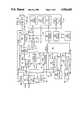
- FIG. 2is a schematic block diagram of a telephone answering machine in accordance with the present invention which could be used at one of the telephone stations shown in FIG. 1.
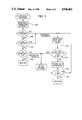
- FIG. 3is a flowchart of the DV interrupt routine in accordance with the present invention which is executed by the microprocessor shown in FIG. 2.
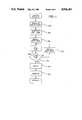
- FIG. 4is a flowchart of the dialing routine in accordance with the present invention which is executed by the microprocessor shown in FIG. 2 upon being entered from the DV interrupt routine shown in FIG. 3.
- the present inventionconstitutes a telephone answering machine which is adapted for use in conjunction with a conventional private branch exchange ("PBX") system such as the system 12 or any other telephone system having "call conferencing" features such as a Centrex system.
- PBXprivate branch exchange
- the PBX system 12is connected on N number of outside telephone lines 16 to the public telephone network whereby calls can be placed to locations remote from the PBX system 12.
- the PBX system 12is also connected on M number of lines 18 to M number of telephone stations 14 such as the individual telephone stations 14a-14j. Each of the telephone stations 14a-14j would ordinarily include a conventional telephone set. It should be noted that the number M of lines 18 (and stations 14) would generally be substantially greater than the number N of outside lines 16. Use of the PBX system reduces the number of outside lines necessary to adequately serve the stations 14.
- the PBX system 12provides for call conferencing by the users of the telephone stations 14.
- call conferencingallows incoming calls to be transferred from one telephone station to another telephone station by direction of a station user (at the initiative of called party).
- the PBX system 12automatically connects the outside line carrying the call to this station (by way of the particular one of the lines 18 connected to the station 14a) in accordance with the number dialed by the calling party.
- the called party using station 14awishes to transfer the call he then simply executes a "hook flash" on his telephone set.
- a hook flashconstitutes a momentary depression of the switch hook of a telephone set.
- the signal produced by the hook flashis interpreted by the PBX system as a call conferencing (or call transfer) request.
- the PBX system 12thereupon disconnects the line carrying the incoming call from telephone station 14a and places the incoming call on hold.
- the called partymay then dial a number corresponding to another telephone such as, for example, telephone station 14d. If this call is answered by a user at telephone station 14d, the party originally called at station 14a may execute another hook flash in response to which the PBX system 12 will couple both of the telephone stations 14a and 14d to the line carrying the original incoming call.
- the called party at telephone station 14amay hang up leaving the outside line carrying the original incoming call connected to the telephone station 14d (by way of the particular one of the lines 18 connected to the station 14d) and leaving the calling party in communication with a user of the station 14d.
- the telephone answering machineincludes a tape deck 30 having two tape assemblies and various other components for processing audio signals and performing other necessary functions associated with recording and playing back announcements and messages under control of the microprocessor 20 in the conventional manner.
- the answering machinealso includes a dual tone multifrequency ("DTMF") receiver 40 and a DTMF generator 50 for processing digit tone signals.
- DTMFdual tone multifrequency
- the microprocessor 20controls the DTMF receiver 40 and the DTMF generator 50 and the other components of the answering machine in accordance with special microcode routines for making call transfers as will be later described in detail.
- the line interface 24is connected to the tip and ring leads of an external telephone line circuit for receiving the input to and providing the output from the answering machine.
- the line interface 24includes a line siezure ("LS") relay 26 which functions to complete the connection between the external telephone circuit and the internal circuitry of the answering machine and thereby take the answering machine off and on hook in response to appropriate control signals from the microprocessor 20.
- the line interface 24employs an optical coupler to generate a signal indicative of a ring signal in the external telephone circuit which is provided to the ring detector 28 on the line 32.
- the ring detector 28processes this signal and supplies a corresponding signal to the microprocessor 20 which the microprocessor 20 can use to determine if an actual ring signal is being received.
- the microprocessor 20determines that a ring signal has been received it supplies an appropriate control signal to the LS relay 26 by way of the driver 34 and the lines 36 and 38 to engage the telephone line and thereby answer the telephone.
- the analog multiplexor 42is connected for separately receiving input signals from the line interface 24, the microphone 44 (which is used for local recording of announcements), the switching module 46, and the DTMF generator 50 on the lines 52, 54, 56 and 58, respectively.
- the analog multiplexor 42functions to select one of these input signals for supply to the audio amplifier 62 on line 64 in response to control signals provided on the line 66 (which contains three leads) from the microprocessor 20.
- the input signal which is selected by the analog multiplexor 42 to be provided to the audio amplifier 62 for amplificationdepends on the mode in which the answering machine is operating.
- the primary function of the audio amplifier 62is to furnish appropriately amplified signals to the switching module 46 on the line 68. However, the audio amplifier also supplies a signal on the line 72 to the voice control component 74. The voice control component 74 processes this signal and provides a corresponding signal to the microprocessor 20 which the microprocessor 20 can use to determine when, among other things, speech related signals are not being provided on the external telephone circuit.
- the audio amplifier 62can also receive an input signal from the automatic gain control component 76 on the line 78. This gain control signal is used to regulate the output of the audio amplifier 62 during recording operations so that the output of the audio amplifier 62 can be maintained at a consistent level.
- the switching module 46receives an input signal on the line 68 and provides output signals on the lines 56, 82, 84 and 86.
- the line 88connects the switching module 46 to the tape head component 92 and can serve both as an output line from the module 46 during recording and as an input line to the module 46 during playback.
- the switching module 46functions to select when the analog multiplexor 42, the line interface 24, the speaker amplifier 100 (and the speaker 102 which is used for local playback of messages), the tape heads 92 and/or the automatic gain control component 76 will receive input signals on the lines 56, 82, 84, 88 and 86, respectively.
- the switching module 46provides its selection function in response to control signals supplied by the microprocessor 20 on the line 94 and by the solenoid driver 96 on line 98.
- the operations of the analog multiplexor 42 and the switching module 46are coordinated by the microprocessor 20 in order to provide the proper routing of audio signals within the answering machine depending on the mode in which the answering machine is operating. For example, when an announcement is being played to a calling party, an audio signal is picked up by the announcement head in the tape head component 92 and proceeds on line 88 to the switching module 46, from the module 46 on line 56 to analog multiplexer 42, from the multiplexor 42 on line 64 to audio amplifier 62 and from the amplifier 62 on line 68 again to module 46 from where it is directed on line 82 to line interface 24.
- an audio signalproceeds from the line interface 24 on line 52 to the analog multiplexer 42, from the multiplexer 42 on line 64 to the audio amplifier 62, from the amplifier 62 on line 68 to the switching module 46 and finally from the module 46 on lines 86 and 88 to the gain control component 76 and the message head in the tape head component 92.
- the tape head component 92is included in a conventional tape deck 30 which also comprises two hall devices 114, three solenoids 116 and a motor unit 118.
- the tape deck 30is adapted for using two tape assemblies for separately recording and playing back announcements for calling parties and messages from calling parties.
- the hall devices 114function magnetically for providing signals to the microprocessor 20 indicative of when the tape assemblies are being properly driven by the motor unit 118.
- the solenoids 116are controlled by the microprocessor 20 by means of the solenoid driver 96 to engage the motor 118 for driving the tape assemblies as required for recording, playback and fast forward operations.
- the motor 118provides the mechanical action necessary for driving the tape assemblies in accordance with electrical power supplied by the motor driver 122 which is also controlled by the microprocessor 20.
- the power supply 124provides a stable source of 5 V and 12 V DC power as required for the functioning the active components of the answering machine.
- the display 126provides a visual indication of various information relating to the operations of the answering machine including, for example, the number of messages recorded from calling parties.
- the display 126consists of two decimal digits which are controlled in accordance with signals supplied by the microprocessor 20 on the line 128 and over the bus 132 which contains four two way data transmission leads.
- the input panel 134includes a number of input keys whereby the user can provide different types of input signals to the microprocessor 20 on the line 136 and over bus 132 for controlling the functioning of the answering machine.
- the dual tone multifrequency (“DTMF") receiver 40also receives the audio input signals (digit tones) provided by the line interface 24 on line 144 which is connected to the output line 52 from the line interface 24.
- the DTMF receiver 40signals the microprocessor 20 on line 146 when it receives a valid digit tone signal. If such a signal is received during message recording, the microprocessor 20, thereafter interrupts its operations and runs the DV interrupt routine shown in FIG. 3.
- the line 148is used to transmit the required enable signals to the DTMF receiver 40 for its proper operation.
- step 200the microprocessor 20 reads data representing the digit tone received by the DTMF receiver 40 from the DTMF receiver 40 over the bus 132 and proceeds to step 202.
- step 202the microprocessor 20 compares this data from the DTMF receiver 40 to data corresponding to a # digit (symbol). If the data corresponds to a # digit the microprocessor 20 proceeds to step 204. If the data does not correspond to the # digit, the microprocessor 20 proceeds to the step 206.
- step 206the microprocessor 20 compares the data from the DTMF receiver 40 to data corresponding to a * digit (symbol).
- step 208the microprocessor compares the data to data corresponding to a .0. digit. If the data corresponds to the .0. digit, the microprocessor 20 proceeds to the dialing routine shown in FIG. 4 (eventually leading to call transfer to an operator). If the data does not correspond to a .0. digit the microprocessor 20 returns to the primary message recording routine.
- step 204the microprocessor reads the data for the next digit tone received by the DTMF receiver 40 over the bus 132. Thereafter, the microprocessor 20 executes step 210 in which it compares the data read in step 204 to data for a # digit and data for a * digit. If the data corresponds to either a # or a * digit, the microprocessor 20 proceeds to the dialing routine shown in FIG. 4 (eventually leading to call transfer). If the data does not correspond to either a # or a * digit, the microprocessor 20 executes step 212 in which it stores the data for the digit compared in step 210 in memory and proceeds to step 214.
- step 214the microprocessor 20 checks to see if 15 digits worth of data have been previously stored in memory. If data for 15 digits have not been stored in memory, the microprocessor 20 jumps back to again execute step 204 (and read data for another digit). If data for 15 digits have been stored in memory, the microprocessor 20 returns to the primary message recording routine. Steps 204,210,212 and 214 constitute a loop for storing a set of data corresponding to the digits of a telephone number, extension number or operator number to which the calling party desires to be transferred.
- the DTMF generator 50generates digit tone signals which are provided over the line 58 to the analog multiplexer 42.
- the DTMF generator 50operates in accordance with data signals supplied over the bus 132 by the microprocessor 20.
- the line 154is used by the microprocessor 20 to transmit the required enable signals to the DTMF generator 50 for its proper operation.
- the digit tone signals from the DTMF generator 50are routed from the analog multiplexor 42 to the audio amplifier 62 on line 64, from the amplifier 62 to the switching module 46 on line 68 and from the module 46 to the line interface 24 on line 82 in response to control signals from the microprocessor 20.
- step 220the microprocessor executes a hook flash operation by utilizing the LS relay 26.
- the microprocessor 20then proceeds to step 222 in which it delays further operations long enough to allow the PBX system 12 to provide a dial tone signal on the external telephone circuit.
- step 224the microprocessor 20 proceeds to step 224 in which it recalls from memory the data corresponding to the first digit received.
- step 226it regulates the operation of the DTMF generator 50 to generate a digit tone signal in accordance with data signals supplied over the bus 132 corresponding to the digit recalled.
- the microprocessor 20also controls the analog multiplexer 42 and switching module 46 to route the dial tone signal to the line interface 24 (and the external telephone line circuit). Individual digits may be thereby effectively "dialed" by the answering machine.
- step 228it checks to see if the last digit in memory has been dialed (i.e. used for generating a digit tone). If the last digit has not been dialed, the microprocessor executes step 230 and recalls the next digit in the order in which the data for the digits was received. Thereafter, the microprocessor jumps back to again execute step 226. Steps 226, 228 and 230 constitute a loop which is operative for dialing all of the digits in memory in the order received. When the last digit has been dialed the microprocessor 20 proceeds to step 232 in which it delays further operations for long enough to allow the PBX system 12 to make the necessary line connections to the telephone station dialed.
- step 234it breaks the circuit connection to the answering machine by means of the LS relay 26 and effectively hangs up thereby taking the answering machine on hook.
- the line carrying the original incoming call from the calling partyremains coupled to the telephone station dialed by the answering machine.
- the original calling partyis placed in communication with the party on the telephone at the number dialed by the answering machine in accordance with the number corresponding to the digit tones provided by the calling party.
- the microprocessor 20returns to the main program governing the operation of the answering machine.
- the DV interrupt and dialing routinesare subject to time limitations for completion so that, for instance, should required signals fail to be received the microprocessor 20 will eventually return to its main program.
Landscapes
- Engineering & Computer Science (AREA)
- Signal Processing (AREA)
- Telephonic Communication Services (AREA)
Abstract
Description
Claims (8)
Priority Applications (1)
| Application Number | Priority Date | Filing Date | Title |
|---|---|---|---|
| US07/162,482US4926461A (en) | 1987-01-12 | 1988-03-01 | Telephone answering machine having call transfer capabilities |
Applications Claiming Priority (2)
| Application Number | Priority Date | Filing Date | Title |
|---|---|---|---|
| US222287A | 1987-01-12 | 1987-01-12 | |
| US07/162,482US4926461A (en) | 1987-01-12 | 1988-03-01 | Telephone answering machine having call transfer capabilities |
Related Parent Applications (1)
| Application Number | Title | Priority Date | Filing Date |
|---|---|---|---|
| US222287AContinuation-In-Part | 1987-01-12 | 1987-01-12 |
Publications (1)
| Publication Number | Publication Date |
|---|---|
| US4926461Atrue US4926461A (en) | 1990-05-15 |
Family
ID=26670099
Family Applications (1)
| Application Number | Title | Priority Date | Filing Date |
|---|---|---|---|
| US07/162,482Expired - LifetimeUS4926461A (en) | 1987-01-12 | 1988-03-01 | Telephone answering machine having call transfer capabilities |
Country Status (1)
| Country | Link |
|---|---|
| US (1) | US4926461A (en) |
Cited By (24)
| Publication number | Priority date | Publication date | Assignee | Title |
|---|---|---|---|---|
| US5062133A (en)* | 1989-07-07 | 1991-10-29 | Logotronix Incorporated | Multi-function telephone call management system |
| DE4040212A1 (en)* | 1990-12-15 | 1992-06-17 | Christoph Massoth | Telephone answering machine accessory for urgent calls - responds to urgent call identification code to switch through call to telephone |
| US5168517A (en)* | 1989-03-13 | 1992-12-01 | Herbert Waldman | Apparatus and methods for selectively forwarding telephone calls |
| US5206900A (en)* | 1991-05-31 | 1993-04-27 | David Callele | Automated attendant |
| WO1994009603A1 (en)* | 1992-10-08 | 1994-04-28 | Newton Communications, Inc. | Private branch exchange system and methods for operating same |
| US5392339A (en)* | 1990-10-18 | 1995-02-21 | Fuji Xerox Co., Ltd. | Telephone transfer apparatus using a special signal for transfer in facsimile communication |
| US5392332A (en)* | 1992-05-27 | 1995-02-21 | Phonemate, Inc. | Shared line telephone answering system with a telephone line-powered disconnect module |
| US5392335A (en)* | 1994-01-13 | 1995-02-21 | At&T Corp. | Arrangement for preventing perpetration of toll fraud through an adjunct processor |
| WO1995018501A1 (en)* | 1993-12-30 | 1995-07-06 | Gte Laboratories Incorporated | Method and apparatus for message delivery using local visual/audible indication |
| US5432844A (en)* | 1992-06-26 | 1995-07-11 | Phonemate, Inc. | Shared line answering system with enhanced extension device features |
| US5524139A (en)* | 1994-07-15 | 1996-06-04 | Boston Technology, Inc. | System for automatic access to automated telephonic information services |
| WO1998000985A1 (en)* | 1996-06-28 | 1998-01-08 | Mci Communications Corporation | Personal communication device voice mail notification apparatus and method |
| US5734710A (en)* | 1994-07-19 | 1998-03-31 | U.S. Philips Corporation | Communication system having a service feature which can be activated and/or deactivated |
| US5764731A (en)* | 1994-10-13 | 1998-06-09 | Yablon; Jay R. | Enhanced system for transferring, storing and using signaling information in a switched telephone network |
| US5784437A (en)* | 1991-03-28 | 1998-07-21 | Nynex Science & Technology, Inc. | Electronic switch connected to intelligent peripheral while permitting call processing of dialed digits |
| US5870463A (en)* | 1995-05-25 | 1999-02-09 | Samsung Electronics Co., Ltd. | Answering telephone using three-party call service |
| US6229880B1 (en) | 1998-05-21 | 2001-05-08 | Bell Atlantic Network Services, Inc. | Methods and apparatus for efficiently providing a communication system with speech recognition capabilities |
| US6233315B1 (en) | 1998-05-21 | 2001-05-15 | Bell Atlantic Network Services, Inc. | Methods and apparatus for increasing the utility and interoperability of peripheral devices in communications systems |
| US20020039412A1 (en)* | 2000-09-26 | 2002-04-04 | Ceglia Michael J. | Hook-flash simulation in parallel with off-hook devices |
| EP1381209A1 (en)* | 2002-07-11 | 2004-01-14 | Fujitsu Limited | Terminal providing call forwarding notification of calling party |
| US20050153729A1 (en)* | 2001-06-01 | 2005-07-14 | Logan James D. | Communication and control system using a network of location aware devices for message storage and transmission operating under rule-based control |
| US7184536B2 (en)* | 2001-09-28 | 2007-02-27 | Intel Corporation | Intelligent forwarded telephone call handling with a call answering system |
| CN102413244A (en)* | 2011-11-21 | 2012-04-11 | 康佳集团股份有限公司 | Method and system for automatically answering and recording mobile phone |
| US8938256B2 (en) | 2000-08-29 | 2015-01-20 | Intel Corporation | Communication and control system using location aware devices for producing notification messages operating under rule-based control |
Citations (11)
| Publication number | Priority date | Publication date | Assignee | Title |
|---|---|---|---|---|
| US3867582A (en)* | 1973-06-12 | 1975-02-18 | United Business Communications | Remote control for private automatic branch telephone exchange |
| US3989901A (en)* | 1975-04-30 | 1976-11-02 | Message Center Systems, Inc. | Optional telephone answering system |
| US4086438A (en)* | 1977-03-07 | 1978-04-25 | Teletech Corporation | Automatic interconnection system |
| US4376875A (en)* | 1980-05-16 | 1983-03-15 | Mitel Corporation | Keyless and indicatorless local telephone switching system |
| US4476349A (en)* | 1982-03-30 | 1984-10-09 | At&T Bell Laboratories | Call message service |
| US4484031A (en)* | 1982-06-21 | 1984-11-20 | Zale Corporation | Interface circuit for a telephone system |
| US4591664A (en)* | 1982-11-23 | 1986-05-27 | Michael Freeman | Multichannel interactive telephone answering apparatus |
| US4625081A (en)* | 1982-11-30 | 1986-11-25 | Lotito Lawrence A | Automated telephone voice service system |
| US4645879A (en)* | 1985-02-08 | 1987-02-24 | Telelogic, Inc. | Call-routing device |
| US4737982A (en)* | 1984-04-19 | 1988-04-12 | Boratgis James P | Reprogrammable call forwarding device |
| US4747124A (en)* | 1982-09-28 | 1988-05-24 | Opcom | PBX telephone call control system |
- 1988
- 1988-03-01USUS07/162,482patent/US4926461A/ennot_activeExpired - Lifetime
Patent Citations (11)
| Publication number | Priority date | Publication date | Assignee | Title |
|---|---|---|---|---|
| US3867582A (en)* | 1973-06-12 | 1975-02-18 | United Business Communications | Remote control for private automatic branch telephone exchange |
| US3989901A (en)* | 1975-04-30 | 1976-11-02 | Message Center Systems, Inc. | Optional telephone answering system |
| US4086438A (en)* | 1977-03-07 | 1978-04-25 | Teletech Corporation | Automatic interconnection system |
| US4376875A (en)* | 1980-05-16 | 1983-03-15 | Mitel Corporation | Keyless and indicatorless local telephone switching system |
| US4476349A (en)* | 1982-03-30 | 1984-10-09 | At&T Bell Laboratories | Call message service |
| US4484031A (en)* | 1982-06-21 | 1984-11-20 | Zale Corporation | Interface circuit for a telephone system |
| US4747124A (en)* | 1982-09-28 | 1988-05-24 | Opcom | PBX telephone call control system |
| US4591664A (en)* | 1982-11-23 | 1986-05-27 | Michael Freeman | Multichannel interactive telephone answering apparatus |
| US4625081A (en)* | 1982-11-30 | 1986-11-25 | Lotito Lawrence A | Automated telephone voice service system |
| US4737982A (en)* | 1984-04-19 | 1988-04-12 | Boratgis James P | Reprogrammable call forwarding device |
| US4645879A (en)* | 1985-02-08 | 1987-02-24 | Telelogic, Inc. | Call-routing device |
Non-Patent Citations (2)
| Title |
|---|
| Telesensory Speech Systems, Manual, T/VIS Application Note AN Ol, Receiving DTMF While Talking , pp. 1 4, 1983.* |
| Telesensory Speech Systems, Manual, T/VIS Application Note AN-Ol, "Receiving DTMF While Talking", pp. 1-4, ©1983. |
Cited By (31)
| Publication number | Priority date | Publication date | Assignee | Title |
|---|---|---|---|---|
| US5168517A (en)* | 1989-03-13 | 1992-12-01 | Herbert Waldman | Apparatus and methods for selectively forwarding telephone calls |
| US5062133A (en)* | 1989-07-07 | 1991-10-29 | Logotronix Incorporated | Multi-function telephone call management system |
| US5392339A (en)* | 1990-10-18 | 1995-02-21 | Fuji Xerox Co., Ltd. | Telephone transfer apparatus using a special signal for transfer in facsimile communication |
| DE4040212A1 (en)* | 1990-12-15 | 1992-06-17 | Christoph Massoth | Telephone answering machine accessory for urgent calls - responds to urgent call identification code to switch through call to telephone |
| US5784437A (en)* | 1991-03-28 | 1998-07-21 | Nynex Science & Technology, Inc. | Electronic switch connected to intelligent peripheral while permitting call processing of dialed digits |
| US5206900A (en)* | 1991-05-31 | 1993-04-27 | David Callele | Automated attendant |
| US5392332A (en)* | 1992-05-27 | 1995-02-21 | Phonemate, Inc. | Shared line telephone answering system with a telephone line-powered disconnect module |
| US5432844A (en)* | 1992-06-26 | 1995-07-11 | Phonemate, Inc. | Shared line answering system with enhanced extension device features |
| US5592473A (en)* | 1992-10-08 | 1997-01-07 | Newton Communications, Inc. | Private branch exchange system and methods for operating same |
| WO1994009603A1 (en)* | 1992-10-08 | 1994-04-28 | Newton Communications, Inc. | Private branch exchange system and methods for operating same |
| WO1995018501A1 (en)* | 1993-12-30 | 1995-07-06 | Gte Laboratories Incorporated | Method and apparatus for message delivery using local visual/audible indication |
| US5392335A (en)* | 1994-01-13 | 1995-02-21 | At&T Corp. | Arrangement for preventing perpetration of toll fraud through an adjunct processor |
| US5524139A (en)* | 1994-07-15 | 1996-06-04 | Boston Technology, Inc. | System for automatic access to automated telephonic information services |
| US5734710A (en)* | 1994-07-19 | 1998-03-31 | U.S. Philips Corporation | Communication system having a service feature which can be activated and/or deactivated |
| US5764731A (en)* | 1994-10-13 | 1998-06-09 | Yablon; Jay R. | Enhanced system for transferring, storing and using signaling information in a switched telephone network |
| US5870463A (en)* | 1995-05-25 | 1999-02-09 | Samsung Electronics Co., Ltd. | Answering telephone using three-party call service |
| DE19618785B4 (en)* | 1995-05-25 | 2005-06-09 | Samsung Electronics Co., Ltd., Suwon | A method for automatically connecting an incoming call to a foreign office in an automatic answering telephone in which the service "Toggle" is allowed |
| WO1998000985A1 (en)* | 1996-06-28 | 1998-01-08 | Mci Communications Corporation | Personal communication device voice mail notification apparatus and method |
| US5802466A (en)* | 1996-06-28 | 1998-09-01 | Mci Communications Corporation | Personal communication device voice mail notification apparatus and method |
| US6741677B2 (en) | 1998-05-21 | 2004-05-25 | Verizon Services Corp. | Methods and apparatus for providing speech recognition services to communication system users |
| US6233315B1 (en) | 1998-05-21 | 2001-05-15 | Bell Atlantic Network Services, Inc. | Methods and apparatus for increasing the utility and interoperability of peripheral devices in communications systems |
| US6229880B1 (en) | 1998-05-21 | 2001-05-08 | Bell Atlantic Network Services, Inc. | Methods and apparatus for efficiently providing a communication system with speech recognition capabilities |
| US8938256B2 (en) | 2000-08-29 | 2015-01-20 | Intel Corporation | Communication and control system using location aware devices for producing notification messages operating under rule-based control |
| US20020039412A1 (en)* | 2000-09-26 | 2002-04-04 | Ceglia Michael J. | Hook-flash simulation in parallel with off-hook devices |
| US6947546B2 (en) | 2000-09-26 | 2005-09-20 | Ceglia Michael J | Hook-flash simulation in parallel with off-hook devices |
| US20050153729A1 (en)* | 2001-06-01 | 2005-07-14 | Logan James D. | Communication and control system using a network of location aware devices for message storage and transmission operating under rule-based control |
| US7769364B2 (en)* | 2001-06-01 | 2010-08-03 | Logan James D | On demand voice mail recording system |
| US7184536B2 (en)* | 2001-09-28 | 2007-02-27 | Intel Corporation | Intelligent forwarded telephone call handling with a call answering system |
| EP1381209A1 (en)* | 2002-07-11 | 2004-01-14 | Fujitsu Limited | Terminal providing call forwarding notification of calling party |
| US20040008833A1 (en)* | 2002-07-11 | 2004-01-15 | Fujitsu Limited | Communication terminal |
| CN102413244A (en)* | 2011-11-21 | 2012-04-11 | 康佳集团股份有限公司 | Method and system for automatically answering and recording mobile phone |
Similar Documents
| Publication | Publication Date | Title |
|---|---|---|
| US4926461A (en) | Telephone answering machine having call transfer capabilities | |
| USRE34536E (en) | Call management system with protocol converter and port controller | |
| US4850012A (en) | Automated access facilities for use with key telephone systems | |
| US4922526A (en) | Automated access facilities for use with key telephone systems | |
| US5422937A (en) | Remotely controlled telephone operator simulator | |
| JP2777250B2 (en) | Private branch exchange system | |
| JPS5986357A (en) | Automatic exchange telephone set | |
| JPH0697773B2 (en) | Telephone | |
| US5226072A (en) | Facsimile machine having recording/reproducing apparatus | |
| JP2985134B2 (en) | Message transfer method | |
| JP2560696B2 (en) | Private branch automatic exchange system | |
| JP3134397B2 (en) | Telephone exchange | |
| JPH10271204A (en) | Answering machine and telephone with answering machine function | |
| JPH09135299A (en) | Method and equipment for call processing control and subscriber's terminal equipment | |
| JPS62225053A (en) | Line switching method | |
| JP2500418B2 (en) | Subscriber line voice information transmission device | |
| KR100339529B1 (en) | Method for controlling automatic response about did call in simple switch | |
| JP2811965B2 (en) | Private branch exchange | |
| JPH01180170A (en) | Automatic private branch exchange | |
| JPS6315556A (en) | Controlling system for sending dial tone | |
| JP3295459B2 (en) | Phone | |
| JP2577816B2 (en) | Telephone system | |
| JPH0483458A (en) | Method for sending ring-back tone including guidance | |
| JPH0955808A (en) | Telephone exchange system | |
| JPS6310847A (en) | Transfer telephone system |
Legal Events
| Date | Code | Title | Description |
|---|---|---|---|
| AS | Assignment | Owner name:CODE-A-PHONE CORPORATION, 16261 SE 130TH, CLACKAMU Free format text:ASSIGNMENT OF ASSIGNORS INTEREST.;ASSIGNOR:KUOK, HENRY;REEL/FRAME:004911/0193 Effective date:19880524 Owner name:CODE-A-PHONE CORPORATION,OREGON Free format text:ASSIGNMENT OF ASSIGNORS INTEREST;ASSIGNOR:KUOK, HENRY;REEL/FRAME:004911/0193 Effective date:19880524 | |
| STCF | Information on status: patent grant | Free format text:PATENTED CASE | |
| AS | Assignment | Owner name:CODE-A-PHONE CORPORATION, A CORP OF DE Free format text:MERGER;ASSIGNOR:CODE-A-PHONE CORPORATION, A CORP OF DE. (MERGED INTO) NOLF CORPORATION A CORP OF DE (CHANGE TO;REEL/FRAME:005559/0182 Effective date:19890929 Owner name:MERRILL LYNCH INTERFUNDING INC., NORTH TOWER, 18TH Free format text:SECURITY INTEREST;ASSIGNOR:CODE-A-PHONE CORPORATION, A CORP. OF DE.;REEL/FRAME:005548/0718 Effective date:19901030 | |
| FPAY | Fee payment | Year of fee payment:4 | |
| AS | Assignment | Owner name:BADGER COMMUNICATIONS CORPORATION, WISCONSIN Free format text:ASSIGNMENT OF ASSIGNORS INTEREST;ASSIGNOR:CAP, INC., FORMERLY DOING BUSINESS AS CODE-A-PHONE;REEL/FRAME:007417/0271 Effective date:19950209 | |
| FEPP | Fee payment procedure | Free format text:PAYOR NUMBER ASSIGNED (ORIGINAL EVENT CODE: ASPN); ENTITY STATUS OF PATENT OWNER: SMALL ENTITY | |
| FEPP | Fee payment procedure | Free format text:PAT HOLDER CLAIMS SMALL ENTITY STATUS - SMALL BUSINESS (ORIGINAL EVENT CODE: SM02); ENTITY STATUS OF PATENT OWNER: SMALL ENTITY | |
| REMI | Maintenance fee reminder mailed | ||
| FPAY | Fee payment | Year of fee payment:8 | |
| SULP | Surcharge for late payment | ||
| FEPP | Fee payment procedure | Free format text:PAYER NUMBER DE-ASSIGNED (ORIGINAL EVENT CODE: RMPN); ENTITY STATUS OF PATENT OWNER: SMALL ENTITY Free format text:PAYOR NUMBER ASSIGNED (ORIGINAL EVENT CODE: ASPN); ENTITY STATUS OF PATENT OWNER: SMALL ENTITY | |
| FPAY | Fee payment | Year of fee payment:12 |