US4925444A - Closed multi-fluid delivery system and method - Google Patents
Closed multi-fluid delivery system and methodDownload PDFInfo
- Publication number
- US4925444A US4925444AUS07/083,843US8384387AUS4925444AUS 4925444 AUS4925444 AUS 4925444AUS 8384387 AUS8384387 AUS 8384387AUS 4925444 AUS4925444 AUS 4925444A
- Authority
- US
- United States
- Prior art keywords
- fluid
- flow
- fluid flow
- delivery
- fluids
- Prior art date
- Legal status (The legal status is an assumption and is not a legal conclusion. Google has not performed a legal analysis and makes no representation as to the accuracy of the status listed.)
- Expired - Lifetime
Links
- 239000012530fluidSubstances0.000titleclaimsabstractdescription486
- 238000000034methodMethods0.000titledescription37
- 230000008878couplingEffects0.000claimsabstractdescription14
- 238000010168coupling processMethods0.000claimsabstractdescription14
- 238000005859coupling reactionMethods0.000claimsabstractdescription14
- 230000004044responseEffects0.000claimsdescription14
- 238000012360testing methodMethods0.000claimsdescription9
- 230000000903blocking effectEffects0.000claimsdescription8
- 238000005086pumpingMethods0.000claimsdescription8
- 238000004891communicationMethods0.000claimsdescription6
- 239000000203mixtureSubstances0.000claimsdescription5
- 230000003213activating effectEffects0.000claimsdescription3
- 230000000007visual effectEffects0.000claimsdescription3
- 238000001514detection methodMethods0.000claimsdescription2
- 230000002093peripheral effectEffects0.000claimsdescription2
- 230000001105regulatory effectEffects0.000claimsdescription2
- 238000007789sealingMethods0.000claims1
- 238000001990intravenous administrationMethods0.000abstractdescription6
- 230000003993interactionEffects0.000abstractdescription4
- 229940079593drugDrugs0.000description108
- 239000003814drugSubstances0.000description108
- 239000000243solutionSubstances0.000description41
- 230000006870functionEffects0.000description31
- 238000001802infusionMethods0.000description20
- WCUXLLCKKVVCTQ-UHFFFAOYSA-MPotassium chlorideChemical compound[Cl-].[K+]WCUXLLCKKVVCTQ-UHFFFAOYSA-M0.000description14
- 238000010586diagramMethods0.000description14
- 230000008569processEffects0.000description13
- 230000002829reductive effectEffects0.000description10
- 230000008859changeEffects0.000description9
- 239000007788liquidSubstances0.000description8
- 239000007789gasSubstances0.000description7
- 230000001965increasing effectEffects0.000description7
- 239000001103potassium chlorideSubstances0.000description7
- 235000011164potassium chlorideNutrition0.000description7
- 230000009471actionEffects0.000description6
- 239000002131composite materialSubstances0.000description5
- WQZGKKKJIJFFOK-GASJEMHNSA-NGlucoseNatural productsOC[C@H]1OC(O)[C@H](O)[C@@H](O)[C@@H]1OWQZGKKKJIJFFOK-GASJEMHNSA-N0.000description4
- 239000008280bloodSubstances0.000description4
- 210000004369bloodAnatomy0.000description4
- VYFYYTLLBUKUHU-UHFFFAOYSA-NdopamineChemical compoundNCCC1=CC=C(O)C(O)=C1VYFYYTLLBUKUHU-UHFFFAOYSA-N0.000description4
- 238000002347injectionMethods0.000description4
- 239000007924injectionSubstances0.000description4
- 238000003780insertionMethods0.000description4
- 230000037431insertionEffects0.000description4
- 238000007726management methodMethods0.000description4
- 238000012546transferMethods0.000description4
- 238000004140cleaningMethods0.000description3
- 230000001276controlling effectEffects0.000description3
- 239000008121dextroseSubstances0.000description3
- 238000012377drug deliveryMethods0.000description3
- 229940063190flagylDrugs0.000description3
- 238000011010flushing procedureMethods0.000description3
- 230000000977initiatory effectEffects0.000description3
- 238000002483medicationMethods0.000description3
- FPTPAIQTXYFGJC-UHFFFAOYSA-Nmetronidazole hydrochlorideChemical groupCl.CC1=NC=C([N+]([O-])=O)N1CCOFPTPAIQTXYFGJC-UHFFFAOYSA-N0.000description3
- 230000002572peristaltic effectEffects0.000description3
- 230000002441reversible effectEffects0.000description3
- 230000008093supporting effectEffects0.000description3
- 229960000707tobramycinDrugs0.000description3
- NLVFBUXFDBBNBW-PBSUHMDJSA-NtobramycinChemical compoundN[C@@H]1C[C@H](O)[C@@H](CN)O[C@@H]1O[C@H]1[C@H](O)[C@@H](O[C@@H]2[C@@H]([C@@H](N)[C@H](O)[C@@H](CO)O2)O)[C@H](N)C[C@@H]1NNLVFBUXFDBBNBW-PBSUHMDJSA-N0.000description3
- 230000007704transitionEffects0.000description3
- 210000003462veinAnatomy0.000description3
- FAPWRFPIFSIZLT-UHFFFAOYSA-MSodium chlorideChemical compound[Na+].[Cl-]FAPWRFPIFSIZLT-UHFFFAOYSA-M0.000description2
- 230000036772blood pressureEffects0.000description2
- 210000001185bone marrowAnatomy0.000description2
- 230000006835compressionEffects0.000description2
- 238000007906compressionMethods0.000description2
- 230000003247decreasing effectEffects0.000description2
- 230000000881depressing effectEffects0.000description2
- 201000010099diseaseDiseases0.000description2
- 208000037265diseases, disorders, signs and symptomsDiseases0.000description2
- 229960003638dopamineDrugs0.000description2
- 230000000694effectsEffects0.000description2
- 230000005484gravityEffects0.000description2
- 230000036541healthEffects0.000description2
- 239000012678infectious agentSubstances0.000description2
- 239000003978infusion fluidSubstances0.000description2
- 238000009434installationMethods0.000description2
- NOESYZHRGYRDHS-UHFFFAOYSA-NinsulinChemical compoundN1C(=O)C(NC(=O)C(CCC(N)=O)NC(=O)C(CCC(O)=O)NC(=O)C(C(C)C)NC(=O)C(NC(=O)CN)C(C)CC)CSSCC(C(NC(CO)C(=O)NC(CC(C)C)C(=O)NC(CC=2C=CC(O)=CC=2)C(=O)NC(CCC(N)=O)C(=O)NC(CC(C)C)C(=O)NC(CCC(O)=O)C(=O)NC(CC(N)=O)C(=O)NC(CC=2C=CC(O)=CC=2)C(=O)NC(CSSCC(NC(=O)C(C(C)C)NC(=O)C(CC(C)C)NC(=O)C(CC=2C=CC(O)=CC=2)NC(=O)C(CC(C)C)NC(=O)C(C)NC(=O)C(CCC(O)=O)NC(=O)C(C(C)C)NC(=O)C(CC(C)C)NC(=O)C(CC=2NC=NC=2)NC(=O)C(CO)NC(=O)CNC2=O)C(=O)NCC(=O)NC(CCC(O)=O)C(=O)NC(CCCNC(N)=N)C(=O)NCC(=O)NC(CC=3C=CC=CC=3)C(=O)NC(CC=3C=CC=CC=3)C(=O)NC(CC=3C=CC(O)=CC=3)C(=O)NC(C(C)O)C(=O)N3C(CCC3)C(=O)NC(CCCCN)C(=O)NC(C)C(O)=O)C(=O)NC(CC(N)=O)C(O)=O)=O)NC(=O)C(C(C)CC)NC(=O)C(CO)NC(=O)C(C(C)O)NC(=O)C1CSSCC2NC(=O)C(CC(C)C)NC(=O)C(NC(=O)C(CCC(N)=O)NC(=O)C(CC(N)=O)NC(=O)C(NC(=O)C(N)CC=1C=CC=CC=1)C(C)C)CC1=CN=CN1NOESYZHRGYRDHS-UHFFFAOYSA-N0.000description2
- 238000012986modificationMethods0.000description2
- 230000004048modificationEffects0.000description2
- BQJCRHHNABKAKU-KBQPJGBKSA-NmorphineChemical compoundO([C@H]1[C@H](C=C[C@H]23)O)C4=C5[C@@]12CCN(C)[C@@H]3CC5=CC=C4OBQJCRHHNABKAKU-KBQPJGBKSA-N0.000description2
- 230000000474nursing effectEffects0.000description2
- 239000011780sodium chlorideSubstances0.000description2
- 238000002560therapeutic procedureMethods0.000description2
- 208000030507AIDSDiseases0.000description1
- 208000010444AcidosisDiseases0.000description1
- 241000282326Felis catusSpecies0.000description1
- HTTJABKRGRZYRN-UHFFFAOYSA-NHeparinChemical compoundOC1C(NC(=O)C)C(O)OC(COS(O)(=O)=O)C1OC1C(OS(O)(=O)=O)C(O)C(OC2C(C(OS(O)(=O)=O)C(OC3C(C(O)C(O)C(O3)C(O)=O)OS(O)(=O)=O)C(CO)O2)NS(O)(=O)=O)C(C(O)=O)O1HTTJABKRGRZYRN-UHFFFAOYSA-N0.000description1
- 101001022148Homo sapiens FurinProteins0.000description1
- 101000701936Homo sapiens Signal peptidase complex subunit 1Proteins0.000description1
- 206010020751HypersensitivityDiseases0.000description1
- 102000004877InsulinHuman genes0.000description1
- 108090001061InsulinProteins0.000description1
- 101800000989OxytocinProteins0.000description1
- 101100386054Saccharomyces cerevisiae (strain ATCC 204508 / S288c) CYS3 geneProteins0.000description1
- 206010040047SepsisDiseases0.000description1
- 102100030313Signal peptidase complex subunit 1Human genes0.000description1
- 230000007950acidosisEffects0.000description1
- 208000026545acidosis diseaseDiseases0.000description1
- 230000001154acute effectEffects0.000description1
- 230000007815allergyEffects0.000description1
- FQPFAHBPWDRTLU-UHFFFAOYSA-NaminophyllineChemical compoundNCCN.O=C1N(C)C(=O)N(C)C2=C1NC=N2.O=C1N(C)C(=O)N(C)C2=C1NC=N2FQPFAHBPWDRTLU-UHFFFAOYSA-N0.000description1
- 229960003556aminophyllineDrugs0.000description1
- 230000036592analgesiaEffects0.000description1
- 238000004458analytical methodMethods0.000description1
- QVGXLLKOCUKJST-UHFFFAOYSA-Natomic oxygenChemical compound[O]QVGXLLKOCUKJST-UHFFFAOYSA-N0.000description1
- 230000004888barrier functionEffects0.000description1
- 230000008901benefitEffects0.000description1
- WQZGKKKJIJFFOK-VFUOTHLCSA-Nbeta-D-glucoseChemical compoundOC[C@H]1O[C@@H](O)[C@H](O)[C@@H](O)[C@@H]1OWQZGKKKJIJFFOK-VFUOTHLCSA-N0.000description1
- 230000003115biocidal effectEffects0.000description1
- 230000004397blinkingEffects0.000description1
- 239000003795chemical substances by applicationSubstances0.000description1
- 238000002512chemotherapyMethods0.000description1
- 239000000470constituentSubstances0.000description1
- 238000011109contaminationMethods0.000description1
- 230000008602contractionEffects0.000description1
- 230000001419dependent effectEffects0.000description1
- 230000000994depressogenic effectEffects0.000description1
- 239000000645desinfectantSubstances0.000description1
- 239000003085diluting agentSubstances0.000description1
- 238000004090dissolutionMethods0.000description1
- 239000003937drug carrierSubstances0.000description1
- 238000002651drug therapyMethods0.000description1
- 239000003792electrolyteSubstances0.000description1
- 238000005516engineering processMethods0.000description1
- 230000001605fetal effectEffects0.000description1
- 210000002458fetal heartAnatomy0.000description1
- 235000013305foodNutrition0.000description1
- 239000008103glucoseSubstances0.000description1
- 238000010438heat treatmentMethods0.000description1
- 229960002897heparinDrugs0.000description1
- 229920000669heparinPolymers0.000description1
- 210000000987immune systemAnatomy0.000description1
- 230000001976improved effectEffects0.000description1
- 230000001939inductive effectEffects0.000description1
- 208000015181infectious diseaseDiseases0.000description1
- 208000014674injuryDiseases0.000description1
- 229940125396insulinDrugs0.000description1
- 238000011835investigationMethods0.000description1
- 230000000670limiting effectEffects0.000description1
- 230000007774longtermEffects0.000description1
- 239000000463materialSubstances0.000description1
- 239000011159matrix materialSubstances0.000description1
- 238000005259measurementMethods0.000description1
- 230000007246mechanismEffects0.000description1
- 229910052751metalInorganic materials0.000description1
- 239000002184metalSubstances0.000description1
- 238000012544monitoring processMethods0.000description1
- 229960005181morphineDrugs0.000description1
- 230000005405multipoleEffects0.000description1
- 239000004081narcotic agentSubstances0.000description1
- 239000001301oxygenSubstances0.000description1
- 229910052760oxygenInorganic materials0.000description1
- XNOPRXBHLZRZKH-DSZYJQQASA-NoxytocinChemical compoundC([C@H]1C(=O)N[C@H](C(N[C@@H](CCC(N)=O)C(=O)N[C@@H](CC(N)=O)C(=O)N[C@@H](CSSC[C@H](N)C(=O)N1)C(=O)N1[C@@H](CCC1)C(=O)N[C@@H](CC(C)C)C(=O)NCC(N)=O)=O)[C@@H](C)CC)C1=CC=C(O)C=C1XNOPRXBHLZRZKH-DSZYJQQASA-N0.000description1
- 230000036407painEffects0.000description1
- 229940030215pitocinDrugs0.000description1
- 239000004033plasticSubstances0.000description1
- 239000000843powderSubstances0.000description1
- 238000002360preparation methodMethods0.000description1
- 238000007639printingMethods0.000description1
- 230000001681protective effectEffects0.000description1
- 230000009467reductionEffects0.000description1
- 230000029058respiratory gaseous exchangeEffects0.000description1
- 238000012552reviewMethods0.000description1
- 238000009666routine testMethods0.000description1
- 239000004065semiconductorSubstances0.000description1
- 238000012163sequencing techniqueMethods0.000description1
- 239000012086standard solutionSubstances0.000description1
- 101150035983str1 geneProteins0.000description1
- 239000000126substanceSubstances0.000description1
- 230000001052transient effectEffects0.000description1
- 230000008733traumaEffects0.000description1
- 210000002700urineAnatomy0.000description1
- 230000002227vasoactive effectEffects0.000description1
Images


Classifications
- A—HUMAN NECESSITIES
- A61—MEDICAL OR VETERINARY SCIENCE; HYGIENE
- A61M—DEVICES FOR INTRODUCING MEDIA INTO, OR ONTO, THE BODY; DEVICES FOR TRANSDUCING BODY MEDIA OR FOR TAKING MEDIA FROM THE BODY; DEVICES FOR PRODUCING OR ENDING SLEEP OR STUPOR
- A61M39/00—Tubes, tube connectors, tube couplings, valves, access sites or the like, specially adapted for medical use
- A61M39/02—Access sites
- A61M39/04—Access sites having pierceable self-sealing members
- A—HUMAN NECESSITIES
- A61—MEDICAL OR VETERINARY SCIENCE; HYGIENE
- A61M—DEVICES FOR INTRODUCING MEDIA INTO, OR ONTO, THE BODY; DEVICES FOR TRANSDUCING BODY MEDIA OR FOR TAKING MEDIA FROM THE BODY; DEVICES FOR PRODUCING OR ENDING SLEEP OR STUPOR
- A61M5/00—Devices for bringing media into the body in a subcutaneous, intra-vascular or intramuscular way; Accessories therefor, e.g. filling or cleaning devices, arm-rests
- A61M5/14—Infusion devices, e.g. infusing by gravity; Blood infusion; Accessories therefor
- A61M5/168—Means for controlling media flow to the body or for metering media to the body, e.g. drip meters, counters ; Monitoring media flow to the body
- A61M5/16804—Flow controllers
- A61M5/16827—Flow controllers controlling delivery of multiple fluids, e.g. sequencing, mixing or via separate flow-paths
- Y—GENERAL TAGGING OF NEW TECHNOLOGICAL DEVELOPMENTS; GENERAL TAGGING OF CROSS-SECTIONAL TECHNOLOGIES SPANNING OVER SEVERAL SECTIONS OF THE IPC; TECHNICAL SUBJECTS COVERED BY FORMER USPC CROSS-REFERENCE ART COLLECTIONS [XRACs] AND DIGESTS
- Y10—TECHNICAL SUBJECTS COVERED BY FORMER USPC
- Y10S—TECHNICAL SUBJECTS COVERED BY FORMER USPC CROSS-REFERENCE ART COLLECTIONS [XRACs] AND DIGESTS
- Y10S123/00—Internal-combustion engines
- Y10S123/13—Gas
Definitions
- the inventionpertains to the field of drug delivery systems and methods. More particularly, the invention pertains to apparatus and methods for controllably providing a plurality of different fluids to a single fluid-flow conduit for delivery in predetermined proportions at predetermined rates.
- these fluidsare delivered to the patient by means of a surgically inserted, main-line catheter or at a peripheral site, such as the patient's arm or leg. Because of the condition of many of these patients, it is especially critical that the correct drug doses be administered at the correct rates during the designated periods of time. Further, many such patients become highly vulnerable to infections or may have depressed or damaged immune systems. Therefore, it is important to minimize, to the greatest extent possible, the potential entrance of infectious agents into the flow of fluids being administered.
- a fluid-flow junctionsometimes referred to as a "Y" site, or a "Y” junction is provided. This junction is located in the initial fluid-flow delivery tube.
- the second container of solutionis coupled into an unused input of the "Y" junction.
- the rate of flow of the two solutionscan be readjusted by means of manually operable clamps and drip chambers associated with each of the solution containers and by adjusting the relative heights of the containers.
- a second "Y" junctionit provided located in the administration line associated with the second fluid container is utilized.
- the third fluid-flow containeris coupled into the second "Y" junction and the rates of flow are again, manually adjusted as before.
- U.S. Pat. No. 4,559,036also to Wunsch, a computer controlled set of valves is illustrated.
- the system of this latter Wunsch patentincludes either motor activated or solenoid controlled valves which are connected to the control unit. Further, this system provides for a timing cycle, during which various valves are independently and successively opened for predetermined time intervals to permit the flow of various fluids to a patient.
- sterile, limited use, disposable, fluid-flow transfer setscan be cost-effective. Such sets can also be very effective in minimizing the possibility that infectious agents might inadvertently be delivered to the patient.
- sterile limited-use, transfer setsdo not in themselves solve the problem of controlling the infusion of a variety of different fluids to produce a desired composite fluid flow.
- One known alternateis to use a multiplicity of infusion pumps, each coupled to one or more sets of solution containers.
- two or more lines, each associated with a respective infusion pumpare brought to the patient and are coupled in an aseptic fashion to the patient.
- Such systemstend to be very flexible and are assembled at the patient's bed side. Nevertheless, they result in a cluttered, confusing system and represent substantial control problems from the point of view of the delivered fluid flow.
- Such a systempreferably would provide the ability to prepare planned medications and fluid-flow delivery sequences which would extend over substantial periods of time, such as 24 hours. Further, such systems would preferably utilize main-line catheters for the purpose of reducing the number of or eliminating various vein punctures usually necessary for the delivery process.
- such a systemshould provide for the relatively long-term scheduling of delivered medications, such as over a 24 hour period. Further, such a system should provide assistance to the nursing staff of an institution in a variety of ways. The multiplicity of different infusion pumps should be reduced to the greatest extent possible.
- the systemshould also be relatively user friendly and easy for the provider of care to work with. Further, such a system should assist in recordkeeping such as by generating hard-copy while at the same time being relatively silent in operation to avoid disturbing the patient and unobtrusive in function.
- a closed, multiple-fluid delivery systemcan deliver a plurality of preselected fluids in a preselected sequence via a closed fluid-flow delivery system to an output port.
- the systemincludes a plurality of deformable fluid-flow tubing or conduit members.
- the tubing memberscan have a spike connector at one end for insertion into an access port of an intravenous fluid container.
- Each other end of the tubing memberscarries a selected connector such as a luer twist-lock connector or a hollow piercing needle.
- the systemincludes a fluid-flow junction member into which the second end of each of the conduits is coupled.
- a plurality of electrically controlled occludersone associated with each conduit member, provides for controllably turning the fluid flow from a respective container on and off.
- the fluidenters into the junction member and flows into an output conduit.
- Pumping meansare provided to effect the fluid flow and deliver the combined fluid flow at a controllable rate.
- the electrically actuated occluders, as well as the pumping meansfunction in conjunction with a programmable control unit.
- the programmable control unitincludes means for storing and executing one or more fluid delivery schedules which can extend over a substantial period of time, such as 24 hours and for controlling the on/off sequencing of the occluders as required by the programmed schedules.
- control unitincludes information relating to inter-fluid and drug compatability important in intravenous drug delivery. The compatability between various specified fluids and the drugs compounded into them can be examined prior to activating the scheduled delivery sequences.
- the control unitalso provides control circuitry to actuate pumps to provide the required combination of flow rate and volume delivered at the specified times at the output port.
- Each occludercontrols the on/off flow of fluid from its assigned fluid container.
- the systemintermittently actuates selected occluders for selected periods of time, so as to provide at the output of the junction a plurality of sequentially delivered fluid quanta from a sequence of fluid containers. This is termed fluid multiplexing. These quanta then intermix while flowing through an output fluid-flow conduit to the fluid port, effectively providing essentially simultaneous delivery of multiple fluids.
- the systemis capable of delivering the fluids in a scheduled, nonmultiplexing, intermittent or continuous mode.
- control unitregulates the actuation or timing of the electrically controlled occluders such that as the fluid administration is subjected to scheduled changes over the course of a predetermined time, the scheduled output flow rate is maintained with respect to the various fluids being provided and any fluid-flow transients due to the schedule changes can be minimized. Transients are minimized by inserting compensation phases into the predetermined delivery schedule.
- the electrically energized occluderscan be implemented as solenoid actuated clamps. Each clamp has a biasing mechanical return/fluid shut off spring.
- the clampin response to a first level of applied electrical energy, can move from a first fluid-flow blocking position to a second, fluid flow enabling position.
- the clampcan be held in the second position at a lower level of electrical energy than was required to get there permitting a flow of fluid through the respective fluid delivery conduit with a low expenditure of electrical energy.
- the biasing memberis available to immediately return the clamp to its first, fluid-flow blocking position, in response to the removal of the second level of electrical energy.
- Resilient meansare provided to resiliently slow and stop the movement of the clamp in response to the applied first level of electrical energy. This provides for quiet operation of the clamp as it moves from a closed position to an open position. On closure, the tubing member cushions the moving portion of the clamp.
- a fluid junctionis provided.
- This fluid junction regionincludes a plurality of fluid input ports.
- the fluid input portscan be sealed with a luer type connector or a pierceable septum.
- the pierceable septumhas a thickness on the order 0.25 7 mm to provide for supporting at least two inserted fluid delivery needles simultaneously as well as for reclosing upon removal of an inserted fluid delivery needle.
- the fluid junction of the present inventionprovides a completely sealed fluid flow delivery system.
- this systemcan provide a single combined flow of sterile intravenous fluids from a variety of fluid-flow sources to the patient.
- the fluid junctioncan also include an output port to which is coupled the fluid-flow output conduit.
- a free-end of the fluid flow output conduitin turn can be coupled to the patient.
- An additional portcan be provided to make possible the coupling of two or more of the fluid junction members together to increase the number of fluid sources that can be used as input sources to the output fluid-flow conduit.
- the fluid-flow delivery systemincludes a plurality of flexible fluid-flow delivery conduits, each with a connector at a first end suitable for coupling to a fluid-flow source, such as flexible container of sterile intravenous fluid either compounded or not with drugs.
- a fluid-flow sourcesuch as flexible container of sterile intravenous fluid either compounded or not with drugs.
- each of the conduitscarries a second coupling member for coupling into a fluid junction member.
- the sources of fluid, the conduits and the fluid junction memberWhen coupled together, the sources of fluid, the conduits and the fluid junction member provide a completely closed system in which various sources may be utilized to provide known quantities of selected fluids. These fluids are permitted to pass through the junction member into an output port of the junction member.
- the output conduitcan be of a type which at a free end has a connector couplable to a catheter of a patient.
- the entire fluid flow delivery systemcan be formed as a sterile disposable, single-patient delivery system. After a predetermined period of time the system would be replaced with another similar, sterile disposable delivery system.
- the output fluid flow conduitcan be formed with a smaller diameter region, on the order of 0.065", than other tubing members which can have a diameter on the order of a 0.100 inches. This reduced diameter region provides for more precise control of the volumes of delivered fluids.
- a methodwhich combines a plurality of fluids from different sources into a continuous, predetermined, composite fluid flow at an output port.
- the methodincludes the steps of providing a sequence of known quantities of different fluids, in a predetermined order, at a first end of a fluid-flow output member.
- the methodfurther provides for mixing the various discrete quantities of different fluids in the output member so as to provide at a second end of that member, a continuous fluid-flow having predetermined proportions and at a predetermined rate such that a predetermined volume of each selected fluid is provided at the output port during a selected time interval.
- the methodprovides for checking the compatability of a selected predetermined set of fluids to be provided and any drugs which may be compounded into them to determine that such fluids can be delivered simultaneously without undesired interaction with one another.
- the combined fluid-flow outputcan be delivered to the output port at a controlled rate by a pump. Alternately, the combined fluid-flow output can be delivered by means of the force of gravity.
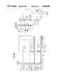
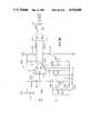
- FIG. 1Ais a schematic view of a prior art, manually stacked multi-fluid delivery system
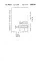
- FIG. 1Bis a set of graphs of fluid flow vs. time for the delivery system of FIG. 1A;
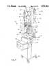
- FIG. 2is a perspective view of a multi-fluid delivery system in accordance with the present invention.
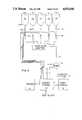
- FIG. 3is an over-all block diagram of the fluid flow system of FIG. 2;
- FIG. 4is a schematic diagram of a disposable set usable with the system of FIG. 2;
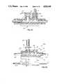
- FIGS. 5A-5Eillustrate alternate forms of the fluid junction member of the system of FIG. 2;
- FIG. 5Fis a fragmentary, enlarged sectional view taken along plane 5F--5F of FIG. 5B;
- FIG. 6is an electronic block diagram of the system of FIG. 2;
- FIG. 7is a detailed block diagram of an occluder electronic interface in the system of FIG. 2;
- FIG. 8is an electro-mechanical diagram of an electrically operated occluder partly in section
- FIG. 9Ais a schematic diagram of an electronic drive circuit for use with the occluder of FIG. 8;
- FIG. 9Bis a graph of voltage applied to an occluder by the drive circuit of FIG. 9A;
- FIGS. 10A-10C taken togetherare a flow diagram illustrating the specification of a plurality of drugs or solutions to be infused by the system of FIG. 2;
- FIG. 11Ais a schematic diagram of the System of FIG. 2 used to provide a three component fluid flow to a patient;
- FIG. 11Bis a set of graphs of fluid flow vs. time for the system of FIG. 2;
- FIG. 11Cis a graph of fluid flow quanta vs time illustrating fluid multiplexing in accordance with the present invention.
- FIG. 12is a view in section of a portion of an output tubing member illustrating spatially spaced-apart quanta of several fluids being delivered by the system of FIG. 2;
- FIGS. 13A and Btogether form a flow diagram of the method of multiplexing in accordance with the present invention
- FIG. 14Aillustrates a prior art apparatus for introducing a second fluid into a flow of a first fluid
- FIG. 14Bis a pair of graphs illustrating the change in concentration in fluids A and B in the tubing member 388 of FIG. 14A as fluid B flows through;
- FIG. 15Aillustrates a system for mixing fluids which employs computer controlled occluders
- FIG. 15Bis a pair of graphs illustrating the change in concentration of fluids A and B in the tubing member 90 of FIG. 15A;
- FIG. 16illustrates the calculated mixing volumes for the systems of FIGS. 14A and 15A during the time intervals when fluids A and B are mixed in tubing members 388 and 90 respectively;
- FIG. 17illustrates an alternate occluder head usable with the computer controlled occluders in accordance with the present invention.
- FIG. 1Aa prior art three-bag infusion System 10 is illustrated in FIG. 1A.
- the desired schedule of fluids to be delivered to a patient Pis 20 ml/hr of fluid 1, 20 ml/hr of fluid 2 and 50 ml of fluid 3 to be delivered at 100 ml/hr.
- the System 10includes three containers, 12, 14 and 16, each of which contains a predetermined quantity of fluids 1, 2 and 3 respectively.
- the containersare coupled by flexible fluid-flow conduits, 20, 22 and 24 along with two "Y" connectors, 26 and 28 and an intermediate tubing section 30 to an output fluid-flow conduit 32.
- Conduit 32is coupled by a catheter C to the patient P.
- Each of the lines 20, 22 and 24includes an infusion pump 21, 23 and 25 respectively.
- Each of the pumps 21, 23 and 25may be adjusted independently.
- containers 12 and 14which are sources for fluids 1 and 2 are adjusted and operating so as to supply 20 ml per hour of fluid in each of lines 20, 22 with the result that in line 32, 40 ml per hour of fluid is being provided to the patient.
- the fluid flow in the line 32 being delivered to the patient Pcontains equal quantities of each fluid as illustrated in the bottom graph of FIG. 1B at all times less than 30 minutes.
- the volume of the line 30is about 1.5 ml.
- the volume of the line 32is about 3.0 ml including the catheter to the patient.
- tubular member 24is opened and adjusted to a desired steady state flow rate of 100 ml per hour for a period of 30 minutes.
- the upper graph of FIG. 1Billustrates the flow of fluid 3 in the tubular member 24.
- an investigation of the fluid flow in the tubular member 30 which represents the composite of fluids 2 and 3, as illustrated in the middle graph of FIG. 1B,demonstrates a very unexpected and undesirable change.
- the rate of flow of fluid 2 in the tubing member 30, which is full of fluid 2jumps to 120 ml per hour. This rate is six times the desired flow rate of fluid 2. This substantially greater flow rate of fluid 2 continues in the line 30 for approximately 0.75 minute. At that time, the spike of fluid 2 drops and the flow rate of fluid 2 returns to its prior predetermined value of 20 ml per hour.
- the fact that fluid 2 has jumped from a desired flow-rate of 20 ml per hour to a flow rate of 120 ml per hour in the line 30might lead to very undesirable results in the patient's therapy.
- the bottom graph of FIG. 1Billustrates the transient fluid flow of the output line 32 to the patient P.
- a spikeappears in the flow rate of fluid 2 being delivered to the patient P.
- the flow rate of fluid 2jumps from the prescribed rate of 20 ml per hour to the patient to approximately 70 ml per hour for about 1.3 minute. It then jumps to 120 ml per hour for about 0.64 minute.
- fluid 1jumps from a prescribed flow rate of 20 ml per hour to a flow rate of approximately 70 ml per hour and then drops to a flow rate of approximately 20 ml per hour.
- the pump 25has stopped pumping fluid 3 from the container 16. However, a quantity of fluid 3 is still in the process of draining through the tubing members 24, 30 and 32. Immediately after the pump 25 has stopped, the overall flow rate in the line 32 drops to 40 ml per hour.
- the 40 ml per hour for about a 9 minute time period illustrated in the lower graph of FIG. 1B at region 34is composed primarily of continuing flow of fluid 3 from lines 30 and 32 with very little flow of fluids 1 and 2.
- the continuing flow rate of fluid 3 in this time intervalis on the order of 28.6 ml per hour.
- the flow rate of fluid 3drops to about 16.7 ml per hour and continues at 16.7 ml per hour for another 4.5 minutes. It's only after this additional period of time that the fluids 1 and 2 return to the prescribed steady state value.
- the system 10 described abovehas failed in several significant ways to deliver the desired fluids at the prescribed flow rates. It is believed that the heretofore unsensed and uncompensated for variations in flow rates due to fluid flow transients may be the source of various artifacts and unexplained test results experienced from time to time in the past. For example, if a test were to be conducted, during the time period indicated by the arrow 34, of the effects of fluid 3 on the patient on the assumption that fluid 3 has already been fully been provided to the patient P, the test results could be erroneous. This erroneous reading could be due to the fact that fluid 3 is still flowing to the patient during this time interval. In fact, fluid 3 continues flowing to the patient for about 7 to 8 minutes longer than nominally expected.
- FIG. 2is a perspective view of a sealed multiple fluid flow delivery system 40 in accordance with the present invention.
- the system 40is supported by framework 42 and contained within housing 44.
- Housing 44is mounted on a plurality of casters 46 to provide easy movability of the system 40.
- a curved supporting member 50At an upper end 48 of the framework 42 is a curved supporting member 50.
- the member 50supports a first set of hangers 52 and a second set of hangers 54.
- the set of hangers 52 and the set of hangers 54are used for the purpose of hanging flexible solution containers such as the illustrated first plurality of solution containers 56 and the illustrated second plurality of solution containers 58.
- the solution container 56ais one member of the plurality of containers 56 which is to be replaced by the second plurality of containers 58 at the end of a predetermined period of time, such as a 24 hour interval. Usually one of the pluralities of containers 56 or 58 at a time is coupled into the system 40.
- the double set of hangers 52, 54facilitates hanging the second, replacement, plurality of containers while the first set continues to provide fluid to the patient.
- Beneath the containers 56 and 58is a generally horizontally extending framework 62.
- the framework 62supports, in spaced-apart relationship, a plurality of electrically actuated clamps or tubing occluders 64.
- Each of the members of the plurality of occluders 64is independently actuatable as is discussed subsequently.
- Associated with the plurality of clamps 64is a plurality of manually operable, lightable actuators 66.
- One actuator from the plurality 66is associated with a corresponding member of the plurality of occluders 64.
- first and second fluid junction members 70 and 72Located beneath the member 62 and slidably affixed thereto are first and second fluid junction members 70 and 72.
- the members 70, 72can be, but need not be identical.
- Linking the solution containers 56 or 58 to the fluid junction members 70 or 72are a plurality of fluid-flow conduit members 74 and 76.
- Each of the members of the plurality 74 and the plurality 76can be formed of flexible medical grade plastic, preferably transparent.
- Each of the members of the pluralities 74 and 76has a first connector, such as a spike connector which can be used to place the conduit in fluid flow communication with a respective fluid-flow container such as 56a, and a second connector at a second end which can be used to place the conduit into fluid-flow communication with the fluid-flow junction 70 or 72.
- a first connectorsuch as a spike connector which can be used to place the conduit in fluid flow communication with a respective fluid-flow container such as 56a
- a second connectorat a second end which can be used to place the conduit into fluid-flow communication with the fluid-flow junction 70 or 72.
- a sealed fluid-flow systemis formed between the plurality of containers 56, the plurality of conduit members 74 and the junction members 70 or 72.
- a sealed systemis formed with the alternate plurality of fluid-flow containers 58, corresponding plurality of fluid-flow conduits 76 and the junction members 70 and 72.
- Each junction member 70 or 72is coupled by an output fluid-flow member 80, 82 respectively to a peristaltic pump 84 and 86.
- the pumps 84 and 86are illustrated in FIG. 2 with manually operable control panels 84A and 86A respectively. Such control panels are a convenience but do not form a part of the present invention.
- the pumps 84, 86are precise linear peristaltic pumps with a dead band at the end of each pumping cycle. The type of pump used is not a limitation of the present invention.
- the output conduits 90 and 92terminate in a luer connector or a piercing cannula and are intended to be coupled directly to a patient's catheter. Such coupling would be in accordance with standard aseptic technique.
- a sealed fluid-flow systemis formed between the fluid flow sources 56 or 58 and the patient P.
- the system 40also includes a video display 96 for the purpose of displaying status and command information to a system operator or attendant. Information can be input to the system 40 via the display 96 using the light pen of a combined light pen and bar code reader 98 electrically coupled to the system 40.
- the hard copy printer 100is especially useful for generating hard copy records of regimes of fluids delivered to the patient P for inclusion in the patient's chart or for purposes of auditing the fluid delivery to the patient.
- the hard copy printer 400can be a spooling printer which contains a non-volatile random access memory.
- the system 40can spool selected information to the memory of the printer 100. In normal operation, that information need not be printed.
- FIG. 3is an overall block diagram of the sealed fluid-flow circuitry of the system 40.
- Each of the containers, such as the container 56ais coupled via a corresponding flexible conduit, such as the conduit 74a through a corresponding occluder, such as the occluder 64a to the fluid-flow junction 70.
- the output line 80 from the fluid-flow junction 70passes through the pump 84. Output from the pump 84 via the output fluid-flow conduit 90 is then coupled to the patient.
- a control system 102is electrically coupled to each of the members of the plurality of electrically actuated occluders 64, the pump 84, the video display 96 and the printer 100.
- the control system 102includes a Data In/Out port.
- FIG. 4illustrates in greater detail the fluid-flow circuitry of the system 40.
- container 56ais coupled to the tubing member 74a.
- the tubing member 74aterminates at a first end in a spike connector 75a.
- a drip chamber 77ais carried by the tubing member 74a.
- the spike connectorcan be used to puncture the access port of the container 56a and as is well-known can also be a sterile connector.
- a second fluid junction member 70acan be coupled to the junction member 70.
- This couplingcan be accomplished by means of a tubing member 70b of a selected length or by means of a double-ended cannula 70c.
- the double-ended cannula 70ccan pierceably engage both the junction member 70 and the junction member 70a.
- member 70has its non-tubing end as a pierceable septum and 70a have a cannula as one end. They can then be joined together by piercing the end of 70 with the cannula of 70a.
- a third wayis to put two needles into a single septum. They are designed to accept two needles without leaking. When so coupled together, the containers 56a-56g all drain into a single tubular output conduit 80.
- Tubular conduit 80has a region 80a which is designed to be inserted into the pump 84 for the purpose of forcing fluid there through at a predetermined rate.
- Tubing section 90includes a first "Y" junction is 90a which is useable for withdrawing air or any other fluid from the composite output fluid.
- the output conduit 90also includes a second "Y" junction 90b for the purpose of injecting additional fluids or medication into the conduit 90 at a site very close to the patient P.
- the tubular member 90has a connection 90c, which can removeably engage a mainline catheter C.
- This type and location of siting on a patientis not a limitation of the present invention.
- Catheter Chas previously been surgically inserted into the patient P. Since the "Y" connector 90b is located relatively close to the catheter C, additional fluids or medications which are injected via the connector 90b will in a very short period of time be infused into the patient P.
- the tubing member 80has a nominal diameter on the order of 0.100 inches.
- the tubing member 90has a nominal diameter on the order of 0.065 inches. The smaller diameter of the member 90 minimizes the volume of fluid residing in the set between the pump, such as the pump 84 or 86, and the patient P. When flushing the line 90, the smaller diameter means that less flush will be needed.
- FIG. 5Ais a perspective view of the fluid-flow junction member 70.
- Junction member 70includes a housing portion 100 which is formed with spaced apart elongated sides 100a. Sides 100a terminate in a planar shield member 100b. As will become more apparent subsequently, when the elongated side members 100a are being gripped manually, the shield member 100b provides protection to the manually gripping fingers of the attendant.
- the elongated side members 100aalso terminate at an end surface 100c. Affixed to the surface 100c are mounting members 102. Mounting members 102 slidably engage slots or openings at the base of the panel 62 for the purpose of removably mounting the fluid junction member 70 on the system 40.
- Each of the fluid input portssuch as a typical port 106 is formed with a cylindrical housing 108.
- the housing 108extends at an angle from a housing 109 in the plurality 104b.
- a pierceable septum 110is surrounded by the housing 108.
- the septum 110is formed of pierceable rubber of a type which is known to reseal itself upon removal of a piercing cannula.
- the septum 110provides a continuous sealed region through which sterile fluids may be injected into the junction member 70.
- the members of the plurality of access ports 104aare each oriented about an axis of rotation which is at a 45 degree angle to the axis of rotation of members of the plurality of input ports 104b.
- the members of the plurality 104aare staggered and spaced between the members of the plurality 104b.
- Each of the ports in the pluralities 104a and 104bcan be covered by a removable cap 111.
- the cap 111can protect the septum and keep it sterile. Covering the ports provides a continuously sterile septum, such as the septum 110 which need not be wiped with a disinfectant prior to use.
- the offset and angular orientation of the ports 104a and 104bis for the purpose of ease of attachment of the conduit members 74 illustrated schematically in FIG. 4.
- the housing 100shown in section defines an internal flow path 112 which has a generally circular cross section.
- a cannula 114which is affixed to the connector 75b can be inserted through a sterile septum, such as a septum 110 and into the region 112. Fluid can then flow from the container 56a through the tubing member 74a and into the central region 112 of the junction member.
- Fluidcan then flow from the junction member 70 through the tubing member 80 to the patient.
- the use of the pierceable septum, such as the septum 110provides for a continuously sealed system for fluid flow between the source, such as the container 56a and the patient P. Removal of the cannula 114 from the septum 110 closes the junction member 70 as the rubber seals the access port created by the cannula 114.
- the fluid junction member 70is always open for receipt of and flow of fluid therethrough.
- the junction member 70does not function as a mixing chamber. Rather, the junction 70 provides only a junction such that a plurality of different fluids from a plurality of solution container such as 56a-56d can sequentially flow into the output tubing member 80.
- each septumsuch as the septum 110 is on the order of 0.25 inches.
- the thick septumprovides a wiping action on insertion of the piercing cannula 114 to further block entrance of any contaminating agent into the closed system.
- the thickness of the septum 110will support 2 or 3 inserted cannuli without tearing or leaking.
- the added thicknessprovides that the septum 110 may be pierced more than once in a 24 hour period, and still continue to properly reseal on removal of the piercing cannula.
- the shield 100bis especially useful in connection with inserting the cannula 114 into the septum 110 in that the person inserting the cannula can manually grip the housing sides 100a without fear of jabbing himself/herself with the cannula 114 since a reasonable amount of force is required to insert the cannula through the thick septum 110.
- septum 110aAffixed to an end of the housing 100 is a septum 110a.
- the septum 110acan be used for the purpose of joining together two junction members such as 70 and 70a illustrated in FIG. 4.
- the dimensions of the channel 112are made as small as possible consistent with fluid flow from the inserted cannuli into the output tubing member 80.
- the junction member 70 at any one timecontains a very small volume of fluid. This minimizes inter-fluid mixing in the junction member 70.
- the channel 112could be formed with other than a circular cross section.
- the exact shape of the channel 112is not a limitation of the present invention.
- the pluralities of injection sites 104a and 104bhave each been illustrated in FIG. 5A with an axes of rotation offset from the other to facilitate independent accessability to each site, the exact orientation of the injection sites with respect to one another is also not a limitation of the present invention.
- FIG. 5Cillustrates an alternate embodiment 120 of the junction member.
- the junction member 120in contradistinction to the junction member 70, is formed with luer twistlock connectors 122.
- Each of the input fluid-flow conduits, such as the conduit 124carries a matching luer connector member 124a which can engage the member 122 permanently affixed to the junction member 120. It will be understood that prior to coupling the tubing member 124 to the junction member 120, the luer connector 122 would be sealed with a removable luer lock cap.
- a luer connector 126 with a septumcould be used.
- a tubing membersuch as the tubing member 74a with the piercing cannula 114 could be used.
- the connector 126could also be sealed with a removable cap 127.
- FIG. 5Dillustrates yet another variation of the junction 70.
- a tubing member 128is coupled to the flow path 112.
- a free end of the tubing member 128carries a spike connector 128a.
- the connector 128acan be used to couple a container of a flush solution to the junction 70.
- FIG. 5Eis a view of yet another junction member 130.
- the junction 130has an elongated housing 132 with a flow path 132a therethrough.
- a plurality of ports 134, with members offset from one another,is also provided.
- a shield 136protects the fingers of an operator inserting a cannula into one of the ports 134 and can also be used as a spring like plate to facilitate the mounting of the junction to a hold bracket.
- the foot member 102ais a continuous member.
- the input ports 108can each be formed having a circular cross section 110b.
- a plurality of capillary spline grooves 110ccan be spaced about the periphery of the circular cross section 110b.
- the groves 110cprovide a means for inflowing fluid to displace the entrapped air in the input ports 108, or prime, when a liquid is initially introduced into the system.
- FIG. 6is a block diagram of a control system 142 usable with the fluid delivery system 40.
- the control system 142includes a main processor system board 144.
- the board 144includes 80C88 and 80C87 programmable processors.
- the system board 144also includes 640 kilobytes of random access memory, 64 kilobytes of read only memory, a graphics controller 148 to drive the monitor 96 and various input-output circuitry. Coupled to the main processor system board 144 is a pump and occluder interface 999.
- the interface 999includes as a secondary processor an 80C88 programmable processor 999a.
- the interface 999also includes an occluder or clamp interface 999b along with EPROM and DRAM memory 999c and a timer counter 999d.
- the pump and occluder interface 999also includes four microcontrollers 999e which communicate with and control the function of pump 84, pump 86 and two optional remote pumps 997 and 998.
- the occluder interface 999bis electrically coupled to occluder drive circuitry 152 which is located adjacent the supporting frame 62.
- the circuitry 152includes a plurality of drive circuits, such as the drive circuit 152a. Each drive circuit is associated with a particular occluder such as the occluder 64a.
- Each occluderhas associated therewith a multielement position sensor 67 which provides feedback via the occluder interface 999b to the processor 999a.
- the sensors 67can be switches, photo-optical or other non-contact position sensors such as capacitive or inductive sensors.
- a general purpose interface 146is coupled to the system board 144 through the bus interface 146b and provides input/output capability. Included are a barcode micro-controller 146a and its associated light pen/bar code reader wand 98; a tone generator 146e and associated audio speaker 150; a power and temperature monitor 146f; a remote nurse call and warning light circuitry 146g; modem interface circuitry 156; a real time clock 146d; 4 Kb RAM battery backup memory 146h; and a watchdog timer to sense timing error 146i. To provide additional input-output communication facilities, the general purpose interface 146 includes a multi-channel RS232 interface 154.
- Power to the system 40is supplied via a power supply 160 which operates off of standard AC power lines and in turn charges a 24 volt battery 162 to permit the unit 40 to continue operating when being moved from one location to another.
- a typical batterycould be an Eagle Picher CFM24V25AH. Battery voltages available to the system 40 include ⁇ 5 V, +6.5 V ⁇ 12 V, +24 V, +27.5 V.
- FIG. 7is a block diagram schematic of the interface circuitry 152 associated with each of the occluders 64.
- the interface circuitry 152includes, for each occluder, a command or output register 166, a feedback buffer 168 and control circuits 170. Data and control signals are transmitted between the occluder interface 999b and the interface circuitry 152 via a communication bus 152b.
- the occluder driver 152ais actuated by setting a bit in the command register 166.
- the set bit on a line 152cprovides an input signal to the driver 152a.
- Output from the driver 152apowers a solenoid coil 172 to open the corresponding occluder.
- Another bit in the output register 166can be set to turn the occluder indicator 67a on and off.
- the set bit on a line 152d and an associated bufferdrive power the indicator 67a.
- the indicator 67acan be continuously on or can blink if desired.
- Feedback inputs to the interface circuitry 152include the manual solenoid override switch 67b and a three position, multi-pole sensing switch 67c. Depression of the switch 67b can cause the occluder 64a to be energized for removal or insertion of a section of tubing.
- the three position sensing switch 67cprovides feedback to the interface as to the status of the occluder.
- Pole S1is normally closed when the occluder is in its closed or unenergized position.
- Pole S2is normally open and closes in an intermediate condition of the occluder.
- Pole S3is normally closed indicates on opening that the occluder is fully energized and open permitting fluid flow.
- the solenoid driver 152aapplies a suitably high voltage and current so as to magnetize the airgap present when the occluder plunger is in its first or closed position.
- the voltage and current to the coil 172is reduced. This second level of electrical energy is sufficient to maintain the occluder in its second or fluid flow permitting position, but yet minimizes heating of the coil 172 and minimizes drain from the battery 162.
- a coil springpushes the occluder 64a to the closed position with a force of the order of 4 pounds.
- the initial voltage applied by the driver 152ais on the order of 16 volts.
- FIG. 8illustrates the structure of the electrically actuated occluder 64a.
- the other occludershave an identical structure.
- Occluder 64aincludes the electrically energizable solenoid coil 172 which surrounds a movable plunger 174.
- the plunger 174is movable in a direction 176 under the influence of the magnetic field generated by the coil 172 from a first, fluid flow blocking position to a second fluid flow enabling position illustrated in FIG. 8.
- a tubing clamping member 174ais carried by the plunger 174. When the occluder is not energized, the clamping member 174a blocks fluid flow through the inserted tubing member 74a.
- An actuating rod 176a also carried by the plunger 174opens and closes switch contacts S1, S2 and S3 as the plunger moves.
- a biasing spring 178forces the plunger 174 to return to its first position upon removal of electrical energy from the coil 172.
- a manually depressable knob 177is provided to manually move the plunger 174 away from the tubing 74a.
- the position sensor 67cis carried by a bracket 179a which is supported by the housing 179b of the solenoid 64a.
- the position sensor 67cis implemented as a three contact mechanical switch assembly.
- the three contacts S1, S2 and S3provide position information to the circuitry 152 for various possible positions of the clamping member or plunger 174.
- the first positioncorresponds to the occluder 64a being deenergized without any tubing having been inserted. In this condition S1 and S3 are closed and S2 is open.
- the second positioncorresponds to the position illustrated in FIG. 8 with the plunger 174 moved to its fully open position permitting fluid to flow through the tubing member 74a. In this condition S1 and S3 are open and S2 is closed.
- the third positionis a test position which is intermediate between the first two positions indicating that the plunger 174 is stuck part of the way between its first or fully closed position and its second open position, as illustrated in FIG. 8. This indicates that the plunger 176 is not in the desired open or closed position.
- S1is open and S2 and S3 are closed.
- the presence of tubing 74a in the occluderis indicated if S1 and S2 are open but S3 is closed.
- the occluder 64aalso includes a plurality of fluid resistant seals.
- Diaphram seal 180a, 180b, an annular seal and band compression and 0 ring seals 180cblock incident fluids from entering the occluder and its associated electrical and electronic components housed in the framework 62.
- the solenoid drive circuit 152aincludes an integrated drive circuit 184 which could be implemented as a L295 integrated circuit manufactured by SGS-Semiconductor Corporation. Outputs from the drive circuit 184 via lines 172a and 172b are coupled to the solenoid coil 172.
- the drive circuit 152ais typical of those in the system 40. Each drive circuit is associated with a different occluder.
- Input to the drive circuit 184 on the line 152cis a five volt or ground signal.
- the drive circuit 152aenergizes the solenoid coil 172 when input signal on the line 152c is on the order of five volts.
- Voltage divider resistors 186a, 186b and 186care connected at a node 186d to form a reference voltage input at pin five of the circuit 184.
- the normally closed contact S3provides a return path to plus five volts except when the plunger 174 has moved to its fully open position.
- a parallel resistor combination including resistors 188a and 188bforms a 0.5 ohm current sensing resistor which is in series with the load.
- the drive current to the solenoid coil 172is set by the value of the voltage at the node 186d of the drive circuit 184. With the parallel resistor values 188a and 188b set to provide 0.5 ohm to ground, the circuit 184 is calibrated to provide 2 amps of current to the coil 172 for each one volt of input at the node 186d.
- the indicated values of the resistors 186a, 186b and 186care chosen to provide 0.6 volts at the node 186d.
- the drive circuit 184supplies 1.2 amps of pull-in current to the solenoid coil 172 until the plunger 174 reaches its fully open position and opens the switch contact S3.
- S3opens, the voltage at the node 186d is set by the combination of 186a, 186b and 186c and is reduced to 0.2 volts.
- the driver circuit 184then supplies 0.4 amps of holding current to minimize power consumption.
- FIG. 9Ba graph of voltage across the solenoid 172 versus time is plotted for a 13.5 ohm solenoid coil. In this case only 16.2 V of the available 24 V supply is applied by the drive circuit 184.
- the pull-in and holding currentscan be adjusted by changing the values of the resistors 186a, 186b, 186c as well as the sensing resistors 188a and 188b.
- the indicated time tocorresponds to the time when the switch contact S3 opens. At that time power to the solenoid coil 172 is reduced from a pull-in value to a holding value.
- FIGS. 10A-10Ctogether form a flow diagram illustrating representative operator initiatable functions or actions which can be undertaken in connection with the system 40.
- a Main Menucan be displayed on the display unit 96.
- a menuPrior to displaying the Main Menu, if desired, a menu could be displayed for the purpose of calibrating the light pen 98.
- Operator displayable screensare included herein in an attached Addendum.
- the Main Menuis illustrated on Screen 1.
- line membersare printed along the left side of the screen.
- a patient's name and identification numberpreviously entered
- date and timecan be displayed.
- previously selected pump A or pump Bcorresponding to pump 84 or pump 86 can be displayed in combination with a previously selected occluder as well as a fluid delivery rate.
- the operatorcan invoke the procedures for IV order entry or call for the list of discontinued orders.
- the operatorcan implement a PAUSE function, a selection of drug specification through the DRUG MASTER screen sequence, or can request a HELP screen. Specification of an action or a function is carried out by the operator using the light pen 98.
- screens illustrated hereinare in a form suitable for printing as textual information that the invention is not limited to such screen formats.
- various selectable actions or functionscan be displayed in reverse video should that be deemed to facilitate operator interaction.
- a selected function or indicia of actioncould be caused to blink, before or after selection, to provide visual feedback to the operator of what has been selected.
- FIG. 10Billustrates a sequence of steps associated with this function.
- Line 2 of Screen 2again displays the patient's name and identification number.
- Lines 22 and 24display the same set of functions as were previously displayed on those lines on Screen 1.
- On line 4 of Screen 2the same pump, occluder and rate information is again displayed as was displayed on line 4 of Screen 1.
- Line 7 of Screen 2indicates specification of a drug/dose.
- the drug potassium chloride with a dose of 20 MEQhas previously been entered.
- the "DRUG/DOSE" identifiercan be displayed in blinking form to indicate the first entry.
- the operatorcan carry out a drug/dose entry by first selecting a displayable keyboard. This is accomplished by selecting the keyboard function on line 22 in a step 202. When so selected, a keyboard screen, Screen 3 appears on the display 96.
- Drug namescan be entered using the alphabetical portion of the keyboard on Screen 3 in lines 10-14.
- the light penis used for selection of each character in a step 204.
- the operatorselects a sequence of alphabetical characters, each of which appears on line 8 of Screen 3 after it has been selected.
- a numeric drug dosecan be selected from the keypad at the right side of the keyboard screen in units assigned from the units indicated on lines 18 and 20 of Screen 3.
- the operator in a step 206selects the ENTER function on line 17 of Screen 3 using the light pen 98. Upon sensing a selection of the RETURN function, the system 40 then returns to Screen 2 with the entered drug and dosage information displayed on lines 7-9.
- the operator in a step 208can then select one of a group of standard solutions from line 10 of Screen 2.
- the "SOLUTION” designatorcan also blink.
- the "RATE” designatorcan be caused to blink by the System 40.
- step 210The operator can then in a step 210 specify the KEYPAD function from line 20 of Screen 2.
- a keypad overlay, illustrated in Screen 4is then displayed on the right hand side of display 96.
- Numeric rate of delivery information on line 10 of Screen 2 and dosage volume information on line 13 of Screen 2can be entered in a step 212.
- the operatorcan enter, with respect to line 13 of Screen 2, the total number of doses to be administered.
- the operatorcan then select in a step 214 one of a group of standard container or bag volumes from line 12 and can specify type of usage from line 14.
- Types of usagecan include intermittent, INTER; continuous, CONT; flushing, FLUSH; keep vein open, KVO; or a combined flush/keep vein open function, FLUSH/KVO.
- the operator in a step 216can then enter scheduling information on line 16 to specify how often the drug or solution is to be provided. Completion of the order is indicated by the operator selecting the ENTER ORDER function in a step 218 on line 20.
- FIG. 10Cillustrates the steps associated with using this Screen 5.
- Each of the drugshas been assigned as illustrated on Screen 5 to the same pump A which can be either pump 84 or pump 86. Each of the drugs has been assigned to a different occluder.
- Assignment of pumps and occluders to previously entered drugscan be carried out by the operator.
- the operatorrequests in a step 230 a PUMP/OCCLUDER function located on the right end of line 7.
- a PUMP/OCCLUDER functionlocated on the right end of line 7.
- Screen 6a keypad for pump and occluder selection is displayed overlaying the right side of Screen 5.
- the first drug, on line 7 of Screen 5can be highlighted for example in reverse video.
- a pumpcan be assigned to that drug along with an occluder in a step 232.
- SCROLL functionline 20 on Screen 5
- each of the drugs on lines 8, 9can be selected in turn.
- each of the drugs displayed on lines 8 and 9can then be assigned to a pump and an occluder.
- the system in a step 234will automatically suppress the pump and occluder key pad overlay Screen after selections are complete.
- the operator in a step 236can then select the INSERT TUBING function on line 9 of Screen 5.
- one of the occluder indicatorssuch as the indicator 67a, which corresponds to occluder 64a will start to flash. This alerts the operator to insert the tubing for the selected drug or solution into that occluder. This can be accomplished by the operator depressing the OCCLUDER OPEN/CLOSE switch, such as the switch 67d. The system 40 will then energize the corresponding occluder, such as the occluder 64a, which will permit insertion of the tubing associated with the selected solution container into the occluder.
- OCCLUDER OPEN/CLOSE switchsuch as the switch 67d
- a second timenotifies the system 40 that the tubing has been positioned in the occluder and the occluder can then deenergized.
- Each of the remaining occluderscan be activated and loaded with a corresponding tubing member in a similar fashion. At this time infusion of the scheduled drugs can be initiated.
- the system 40will then display a Compatibility Summary, with respect to the three drugs previously listed on Screen 5, as illustrated by Screen 7.
- the three previously entered drugsare listed on lines 7, 8 and 9.
- each of the drugsis compared to each of the other two drugs.
- potassium chloridedrug 1 when compared with Tobramycin, drug 2, results in an indicia "C” being displayed.
- the indicia "C”indicates that those two drugs are compatible.
- a comparison of potassium chloride, drug 1 with Flagyl, drug 3indicates an incompatibility.
- the potassium chloridecan be assigned to one of the two pumps and the Flagyl can be assigned to the other of the two pumps.
- This multipump assignmentis illustrated near the right side of Screen 7 in a column with a heading "P".
- a pump occluder keypadis displayed along the right side of Screen 7.
- a FLUSH functionis provided on line 20.
- a flushcan be provided both before and after delivery of any selected drug or fluid.
- Screen 8can be displayed.
- Screen 8provides an identification of scheduled drugs, for example on lines 7, 8 and 9. Additionally, Screen 8 identifies the assigned pumps and occluders along with an indication of scheduled frequency of delivery of the drug or solution.
- a representation of time intervals of delivered drugs during a twenty-four hour periodis displayed with quarter hour increments.
- the SCROLL functionscan be used to move the display through the complete 24 hour time period.
- an operatorcan select a PRINT SUMMARY function which causes the system 40 to then create a hard copy of the summary.
- the system 40provides a Drug Status Display, Screen 9.
- the system 40can also assist a health care provider in fluid management.
- Screen 11provides for forecasting of expected intake volumes of fluids.
- Line 7 of Screen 11provides for entry of a maximum fluid volume over a 24 hour period.
- a displayis provided of currently committed fluid quantities, based on 8 hour time periods. Additionally, a display is provided of currently available quantities of fluids which can be added to those quantities already committed during each 8 hour time period. Hence, Screen 11 provides 8 hour projections as well as daily totals with respect to both volumes of committed fluids and currently available volumes of fluids.
- the system 40could be operated in a mode wherein one solution at a time was to be infused into the patient P.
- potassium chloridewas to be infused continuously.
- Tobramycinwas to be infused intermittently. During the time that tobramycin was being infused, via occluder 2 the potassium chloride would be blocked from flowing via occluder 1.
- two or more fluids and drugscould be simultaneously infused into the patient P.
- simultaneous infusion of multiple drugsutilized systems of the type illustrated in FIG. 1A with results of the type illustrated in FIG. 1B.
- FIG. 11Aillustrates schematically the system 40 coupled to a patient P where 3 containers 56a, 56b and 56c have been coupled to the fluid-flow junction member 70.
- the corresponding electrically actuated occluders 64a, 64b and 64care sequentially opened and closed to permit fluid flow of pulses or quanta of corresponding fluids from the containers 56a, 56b and 56c through the conduit members 74a, 74b and 74c in a predetermined sequence.
- a fluid flow composed of a sequence of discrete pulses or quanta of fluids from the containers 56a, 56b and 56cis formed in the output tubing member 90.
- the same order of fluidsis to be delivered by the system of FIG. 11A as was previously to be delivered with the system 10 of FIG. 1A. That is, 20 ml/hour of fluid 1, 20 ml/hour of fluid 2 and 50 ml of fluid 3 at 100 ml/hour.
- fluid 3 from the container 56cwhich is to be provided at a 100 ml rate to the patient for a 30 minute period, as illustrated at the top most graph of FIG. 11B is initially started at the 15 minute point with a flow rate of about 30 ml per hour. Simultaneously, the flow rates for fluids from containers 56a and 56b have been substantially reduced from 20 ml per hour each to about 10 ml per hour. During the 15-30 minute time interval as illustrated in the bottom graph of FIG. 11B, fluid flow to the patient P continues unchanged at 20 ml per hour of each fluid.
- the flow rate for fluid 3 from the container 56cis increased by the system 40 to 100 ml per hour. This flow rate is maintained until the 55 minute point has been reached. Note that the order, as was the case with the order of FIGS. 1A and 1B calls for 100 ml of fluid 3 to be delivered to the patient P for 30 minutes.
- output to the patient P from the line 90corresponds to 100 ml of fluid 3 for 30 minutes. Notwithstanding the fact that fluid 3 flow from the container 56c has terminated at the 55 minute point, flow to the patient P of fluid 3 continues to the 60 minute point at the prescribed flow rate. Also, during the time period 55-60 minutes, the rate of flow of fluids 1 and 2 has been substantially increased to 70 ml per hour for each fluid as illustrated in the middle graph of FIG. 11B. However, output to the patient P of fluids 1 and 2 as a result of the multiplexing of the present system continues at a 20 ml per hour rate.
- the system 40has delivered exactly the prescribed fluid combination, fluid 1 at 20 ml per hour, fluid 2 at 20 ml per hour and fluid 3 at 100 ml per hour for 30 minutes.
- the prior art stacking system of FIG. 1Adelivered a substantially different fluid flow to the patient.
- the system 40has the capability of automatically multiplexing drugs assigned to a pump if one or more of the drugs which has been assigned is to be infused continuously and one or more of the drugs is to be infused intermittently. In addition, a flush may be assigned to the pump that will be carrying out the multiplexing.
- the operatorcan display Screen 12.
- the drug dopamine in the solution dextroseare being infused through occluder at a 30 ml per hour rate.
- the drug aminophylline in dextroseis being infused through occluder 5 at a 15 ml per hour rate.
- the system 40has indicated that the fluid Heparin is being infused to the patient through occluder 6 at a 25 ml per hour rate.
- the system 40will automatically predict when the infusion of fluid 3 should be initiated or terminated such that the output to the patient corresponds to the ordered fluid flow sequence.
- the 30 minute time periodis a point at which the fluid 3 should be reaching the patient at a 100 ml per hour rate, prior to that time period the system 40 will determine an intermediate time period wherein the fluid 3 should be permitted to flow into the output tubing 90 which is coupled to the patient.
- FIG. 11Cis a graph illustrating the fluid aspects of the multiplexing of the system 40.
- the graph of FIG 11Ccorresponds to the multiplexing operation with respect to the order to be delivered to the patient in the lower graph of 11B.
- fluids 1 and 2are initially each alternately permitted to flow into the fluid flow junction 70 by respective occluders for approximately 11 and 1/2 seconds.
- this initial phasewhich corresponds to a time period of 0 to about 15 minutes there is a steady state condition established wherein an 11 and 1/2 second long pulse or bolus of fluid 1 is permitted to flow into junction 70.
- an 11 and 1/2 second long bolus or pulse of fluid 2is permitted to flow into the fluid flow junction 70.
- the system 40Prior to the 15 minute point, the system 40 has determined that it will be necessary to initiate flow of fluid 3 so as to minimize fluid transients to the patient and so as to deliver the ordered fluids at the required flow rates.
- this compensation phase or interim phasewhich extends from about the 15 minute point to the 30 minute point at which the fluid 3 should be delivered to the patient at a rate of 100 ml per hour, the system 40 is sequentially actuating each of the occluders associated with containers 56a, 56b and 56c.
- the result of this actuationis to continue to provide fluids 1 and 2 in 11.5 second quanta but after fluid 2 to inject a 57.5 second quantum of fluid 3, via occluder 54c, into the fluid flow junction 70.
- This three fluid multiplexing operationis continuously repeated from the 15 minute time point the 30 minute point. This results in a sequence of spatially spaced apart quanta of fluids 1, 2 and 3 moving into the conduit 90 at the input port 90a.
- the sequence of quanta of fluid 1, sequence of quanta of fluid 2 and the sequence of quanta of fluid 3arrive at the output port 90b they will be mixed and provide a composite fluid flow output rate at a 140 ml per hour rate with fluid 1 being provided at a 20 ml per hour rate, fluid 2 being provided at a 20 ml per hour rate and fluid 3 being provided at a 100 ml per hour rate.
- the system 40will again switch.
- the fluid flow ratejumps to 140 ml per hour.
- fluid 1is permitted to flow at approximately for a 3.3 second interval
- fluid 2is permitted to flow for a 3.3 second interval
- fluid 3is permitted to flow for a 16.4 second interval. This sequence is repeated for 25.6 minutes which corresponds to a time of 55.6 minutes.
- the system 40Prior to the 55.6 minute point, the system 40 will have predicted that it will be necessary to terminate flow of fluid 3 from the container 56c. A second compensation phase will be needed. Hence, at that time occluder 64c will be de-energized and flow of fluid 3 from the container 56c ceases. However, flow of fluid from the containers 56a and 56b continues during the time interval between 55.6 minutes and 60 minutes at a rate of 140 ml/hour.
- fluid 1is permitted by occluder 64a to flow for 3.3 second time intervals.
- fluid 2is permitted by occluder 64b to flow for 3.3 second time intervals.
- alternating pulses of fluid 1 and fluid 2are permitted to enter the fluid flow junction 70 and exit to the input port 90a of the conduit 90.
- the spatially spaced apart quanta of fluid 1which are interspersed between the spatially spaced apart quanta of fluid 2 move through the conduit 90 they are mixed and arrive as a stream of 50% fluid 2 at the output port 90b.
- the fluid flow ratedrops to 40 ml per hour and fluids 1 and 2 continue to be sequentially injected into the fluid flow junction 70 for 11.5 second long time intervals. This then results in an output fluid flow to the catheter C at a rate of 20 ml per hour for each fluid.
- FIG. 12is a schematic diagram of a plurality of spaced apart quanta of fluid one, each bearing an identification numeral of F1. Interspersed between the quanta of fluid one is a spaced apart sequence of quanta of fluid two each bearing an identification numeral F2.
- the spaced-apart sequence of quanta of fluid one and the interspersed spaced apart sequence of quanta of fluid twoenter the tubing member 90 at the input port 90a.
- the quantaare mixed while in the tubing member 90 and at the output port 90b is a fluid flow at a designated rate which includes fluids one and two in equal proportions.
- the process of predicting when the system 42 should switch from a first predetermined flow sequence to an intermediate or compensating flow sequence and then to a second predetermined flow sequenceis dependent on the volume of the tubing member 90.
- the tubing member 90shall be assumed to be equal to 10 ml.
- the present multiplexing systemcompensates for effective flow rate errors which occur when a solution's flow rate is changed.
- the system 40can simultaneously deliver a plurality of drugs and solutions with one infusion pump.
- the effective flow rate of each drug at a given timeis equal to the fraction of the drug in the tubing times the initial total (or pump) flow rate. For example, if the tubing 90 is filled with a mixture of 1/4 drug A and 3/4 drug B and the pump rate is 100 ml/hr, then the effective rate of drug A is 25 ml/hr and the effective rate of drug B is 75 ml/hr.
- the effective flow rate of each drugis the same as the desired rate.
- the rate errorsoccur when the pump rate is changed to a new rate, but the drugs in the tubing are mixed in proportion to the previous rates. This causes the effective flow rate of each drug to be in error until the tubing is flushed by the drugs running in the new proportion.
- the system 40automatically determines and inserts an intermediate or compensation phase between the Initial and the Final flow rates when carrying out the multiplexing function.
- This compensation phaseis used to adjust the individual drug rates, in order to properly proportion the drugs in the tubing in preparation for the new flow rates.
- the compensation phaseis initiated ahead of the next scheduled flow rate change by the amount of time required to flush the tubing volume.
- the individual drug proportionsare adjusted to provide the desired mixture of drugs in the tubing at the start of the next scheduled flow rate change, with a total flow rate equal to the Initial flow rate. The result is that the output to the patient P is exactly as prescribed.
- the system 40can adjust the amount of time during which any given occluder is energized. By keeping the original fluid flow rate but adjusting the proportions of the constituent fluids the tubing member 90 can be flushed by the time that the prescribed fluid flow order requires a change to take place in the fluid flow to the patient.
- the multiplexing processis a two step procedure.
- the system 40carries out a continual volume generating process which keeps track of the amount of fluid to be delivered over a period of time in accordance with the rate previously entered by means of Screen 2.
- relative rates for each of the fluids to be deliveredare established.
- accumulatorsare established for each of the fluids. The accumulators keep track of the quantity of fluid that should be delivered in accordance with the previously entered delivery schedule.
- a step 304a base time increment is determined.
- the system 40waits for the duration of the based time increment.
- the contents of each of the accumulatorsis updated. The updated value of each accumulated corresponds to the amount of fluid that should have flowed for the base time increment at the relative rate.
- the system 40then returns to the step 306 and waits for the next time increment.
- the volume generating processcontinues updating accumulator values until new relative rates are provided.
- the process of controlling the occluders assigned to the respective fluids to be deliveredutilizes the continuously updated values in each of the accumulators.
- a pump constant corresponding to volume per revolution, or volume per linear movement in the case of a linear pumpis retrieved.
- one of the accumulatorsis selected.
- the contents of the selected accumulatoris divided by the pump constant. This results in the number of pump revolutions needed to provide the quantity of fluid indicated by the contents of the accumulator.
- the system 40takes the integer part of the number of pump revolutions.
- the systemchecks to see whether or not integer parts have been formed for all accumulators. If more are needed, the system returns to the step 322.
- step 328selects one of the integer parts.
- the system 40opens a corresponding occluder.
- the system 40runs the pump, such as the pump 84 for as many revolutions as corresponds to the selected integer value.
- the open occluderis then closed.
- the value in the corresponding accumulatoris reduced by the amount of fluid just delivered in the step 334.
- the system 40checks to see whether or not all accumulators have been reduced. If not, it returns to the step 330 and selects another integer part associated with another accumulator. If so, the system 40 returns to the step 322 to select an accumulator repeat the process.
- a sequence of pulses or quanta of each of the predetermined fluidsis permitted to flow into the input in 90a of the output conduit 90 and is then pumped to the patient P by the pump 84.
- the above methodproduces the sequences of fluid quanta such as illustrated and previously discussed in FIG. 11C.
- the occludercan preferably be opened and closed during the pump dead band interval. By so limiting the times when occluders can be opened or closed, only fluid quanta corresponding to integer numbers of pump "revolutions" will be delivered.
- drugs or solutionsmay be specified to the system 40 in a variety of ways without departing from the spirit and scope of the present invention.
- a drug or solution programcould be specified through the bar code reader portion of the light pen 98.
- the desired regime of drugs and/or solutionscould be supplied to the system 40 via telecommunications through one of the RS232 ports or the modem 156.
- the system 40could contain in its memory a data base of drug names and doses. The drug names and doses could be displayed on the display unit 96 in response to appropriate input by the operator via the light pen.
- patient informationcan be input to the system 40 via the display unit 96.
- Screen 13illustrates a patient information input screen.
- an operatorcan enter information such as the patient's name on line 7 as well as physical information such as sex and age on line 9, height and weight on lines 12 and 14 and allergies on line 16.
- the printer 100can provide a variety of hard copy reports which are in the nature of historical summaries of patient condition and delivered fluids over various periods of time.
- Report 1attached hereto in the Addendum as Report 1 is a Physician Summary Report which can be generated by the system 40 upon request.
- the reportcan include information concerning vital signs, drugs which have been administered as well as comparisons of drugs to various vital signs.
- system 40can be used for a variety of different purposes. This includes, patient monitoring using invasive and noninvasive sensors. Vital signs, temperature, respiration rate, pressures, and urine output could be monitored. Collected information can be used to turn drug pumps on or off.
- the system 40could be part of a closed loop feedback system that could couple drug dosing algorithms with sensors to create a servo mechanism and maintain prestated physical requirements.
- drug dosing algorithmsinclude vasoactive drugs for blood pressure control and antibiotic pharmacokinetic measurements for disease control.
- the catheters that currently feed drugs into the patient's venal systemcould be scheduled also to draw blood on command into an automatic blood testing system at the bedside for routine tests such as insulin, blood gasses, or electrolytes.
- the system 40could detect fetal stress and automatically alarm and signal reduction in pitocin or other contraction type drugs which are known to create acidosis.
- the system 40can quickly report other drugs given, other supplies given, other foods given, nursing time at the bedside, and all other routine bedside record keeping support tasks necessary for reduced administrative and medical cost containment.
- the system 40could automatically maintain a consistent level of drug dose to the patient.
- Current technologytries to find a drug carrier matrix that dissolves evenly; this would not be necessary with matching of the dissolution curve with the drugs involved.
- physician trending and relationship graphswill provide insight to patient drug response and will assist in patient management.
- This datais available both locally in a patient's room and remotely at the physician's home or office for more responsive drug management.
- the system 40has characteristics which tend to reduce patient sepsis and to reduce patient blood contact to one central IV line, patients who have immunosuppressed conditions can more favorably be treated. These patients include patients receiving chemotherapy, those with AIDS, bone marrow transplant patients, and others.
- the system 40could also be used to assist in patient pain management. With the addition of a small pushbutton on a cord to the patient, analgesia type drugs can be dispensed in predesignated quantity by patient demand. When the patient is alert enough, this is a proven method to reduce total morphine levels while better serving patient needs. Current systems are expensive and bulky. They use special standalone pumps with high cost narcotic drug containers. The system 40 could greatly simplify this technique while significantly reducing cost.
- the improved operational characteristics of the system 40are readily apparent when compared to a known apparatus 380, FIG. 14A, for the purpose of introducing a second fluid, fluid B, into a flow of a first fluid, fluid A.
- the system 380includes a solution container 382 which serves as a source of the fluid A.
- Flow of the fluid A from the container 382is carried by a conventional tubing member 384 which can include a drip chamber 384A.
- the tubing member 384can be clamped shut by a manually operable clamp 384b.
- the tubing member 384terminates at a Y-junction 386. Outflow from the Y-junction 386, via a tubing member 388, passes through a conventional infusion pump 390 and is then delivered to the patient at a rate determined by the setting of pump 390.
- Fluid Bin a container 392 flows therefrom member 394, through a drip chamber 394a and is regulated by a manually operable clamp or occluder 394b. Outflow from the tubing member 394 is coupled through the Y-junction 386 and can then flow into the tubing member 388.
- the two fluid system of FIG. 14Ahas been commonly used in situations were fluid A is being delivered to a patient and it is desirable to interrupt the delivery of fluid A for the purpose of delivering fluid B.
- the volume of the fluid B in the container 392is less than the volume of the fluid A in the container 382.
- the container 382is conventionally lowered by means of a short metal hanger 398.
- the fluid Bwill drain through the tubing member 388 and in the process will interrupt the flow of the fluid A through the tubing member 388.
- FIG. 14Bis a pair of graphs illustrating the change in concentration of fluids A and B in the tubing member 388 as fluid B drains therethrough.
- initially fluid Acorresponds to 100% of the fluid in the tubing member 388.
- the concentration of fluid Adrops and the concentration of fluid B increases toward 100%.
- the concentration of fluid B in the line 388begins to decrease toward zero and the concentration of fluid A in the line 388 returns to 100%.
- percent concentrationsas fluid A is displaced by fluid B and fluid B is displaced by fluid A, are plotted against fraction numbers of fluid in the line 388.
- the fluid delivery rate in the line 388is 120 ml/hour.
- the fluid Acould be for example, glucose and the fluid B could be saline.
- FIG. 16illustrates the calculated mixing volume for the system of FIG. 14A during the time intervals when fluids A and B are mixed in the line 388.
- the concentration of Fluid Bis increasing.
- the concentration of Fluid Ais increasing.
- Total calculated mixing volumecorresponds to 20.2 ml.
- Fluid initial mixing volumewas calculated starting from when fluid B first appeared and ending when fluid A fell below 5% of its initial concentration. Fluid final mixing volume was calculated similarly.
- the volume of the mixed fluids A and B during the transition intervals when fluid A is decreasing in the line 90 and fluid B is increasing as well as the reverse when fluid B is decreasing and fluid A is increasinghas been calculated to be on the order of 11.9 ml.
- This latter valueis about one-half the earlier noted value of mixing volume for the system 380.
- the volume of mixed fluids A and Bis substantially less with the system 40.
- the possibility of interaction between the two fluidshas been reduced.
- better controlhas been achieved over the delivery of the fluids to the patient.
- FIG. 17illustrates an alternate occluder head 400 usable with the computer controlled occluders 64.
- the occluder head 400includes a cylindrical solenoid body portion 402 defining an interior region 404 which is in part occupied by a solenoid coil 406.
- An extension 402ais crimped onto body portion 402.
- a solenoid armature 408Centrally located and axially moveable within the housing 402 is a solenoid armature 408.
- the armature 408is moveable in a direction 410 in response to electrical energy having been applied to the solenoid coil 406.
- a compression spring, comparable to the spring 178can be used to move the armature 408 opposite the direction 410 when the solenoid coil 406 is denergized.
- the armature 408carries a cylindrical spacing member 412 which terminates in a disk-shaped head 414.
- the head 414when the solenoid coil 406 is de-energized will pinch closed the tubing member 74a.
- the occluder head 400also carries a fixedly located clamping member 420.
- the member 420terminates adjacent the tubing member 74a in a curved extension 422.
- the solenoid armature 408moves opposite the direction 410, the disk-shaped clamping member 414 forces a region 424 of the tubing member 74a against the curved member 422 which clamps the tubing member 74A shut.
- the coil 406is energized, the armature 408 and the disk-shaped member 414 move in the direction 410 away from the region 424 thus permitting a flow of fluid through the tubing member 74A.
- annular seal 430located between a groove 402b in the housing extension 402a groove 414a in the disk-shaped member 414 seals the occluder head from incident spilled fluids as well as from cleaning fluids which might be used for the purpose of cleaning the exterior surfaces of the system 40.
- the annular seal of 430could be formed of any flexible material which will be resistant to fluids and cleaning solutions of a type normally found in a healthcare environment.
- preprinted data in a bar code formatcan be conveniently and quickly entered into the system 40.
- labels on the solution containers 56can also be printed with bar code format encoded information identifying the related solutions, drugs, delivery rates and volumes. Such information can all be entered into the system 40 by means of the bar code reading portion of the member 98.
- sensorscan be coupled to the system 40 for the purpose of sensing and recording other patient related data.
- sensorscould include but are not limited to blood pressure sensors, temperature sensors or the like.
- a flush fluidsuch as saline
- salinecan be used to separate two otherwise incompatible fluids. Imposing a requirement that there be a quantum of flush fluid between spaced apart quanta of incompatible fluids can be carried out through the display monitor 96.
- a gassuch as air, or oxygen could be used as a flush.
- the gaseous flush quantum which is located between two spaced apart quanta of incompatible fluidsis withdrawn from the patient delivery tubing member 90 immediately prior to coupling to the catheter C at the end 90c.
- a gasis used as a flush fluid to space apart incompatible quanta of liquids, it is also possible to precisely measure the length of each liquid quantum and accumulate the number of quanta which are delivered to the patient to provide very precise volume and rate information.
- air pressurecan be used as an alternate to the pump 84 to drive the delivery of fluid in the line 90 to the patient.
- the driving gasis injected into the tubing member 90, perhaps also functioning as a flush fluid, and forcing the fluid therein to the patient.
- system 40could be used in a gravity flow mode without a pump. This results in a low pressure injection of fluid into the patient.
- tubing member 90which can have a nominal diameter on the order of 0.065 inches is a disposable which is regularly replaced.
- the replacement tubingmay have an actual diameter which varies somewhat from the nominal value of the diameter.
Landscapes
- Health & Medical Sciences (AREA)
- Heart & Thoracic Surgery (AREA)
- Animal Behavior & Ethology (AREA)
- General Health & Medical Sciences (AREA)
- Anesthesiology (AREA)
- Biomedical Technology (AREA)
- Hematology (AREA)
- Life Sciences & Earth Sciences (AREA)
- Veterinary Medicine (AREA)
- Engineering & Computer Science (AREA)
- Public Health (AREA)
- Pulmonology (AREA)
- Vascular Medicine (AREA)
- Infusion, Injection, And Reservoir Apparatuses (AREA)
- Feeding, Discharge, Calcimining, Fusing, And Gas-Generation Devices (AREA)
- Structure Of Belt Conveyors (AREA)
- Catching Or Destruction (AREA)
- Pipeline Systems (AREA)
Abstract
Description
__________________________________________________________________________Effective flow rates (ml/hr): A B Total __________________________________________________________________________Initial 20 60 80Transition 25 75 100 Final 40 60 100 __________________________________________________________________________Transition calculations: A B __________________________________________________________________________Tubing mix 20/80 = 0.25 60/80 = 0.75 Effective rate 0.25*100 = 25 ml/hr 0.75*100 = 75 ml/hr Rate error ##STR1## ##STR2## __________________________________________________________________________
Claims (59)
Priority Applications (14)
| Application Number | Priority Date | Filing Date | Title |
|---|---|---|---|
| US07/083,843US4925444A (en) | 1987-08-07 | 1987-08-07 | Closed multi-fluid delivery system and method |
| CA000573511ACA1317007C (en) | 1987-08-07 | 1988-07-29 | Closed multi-fluid delivery system and method |
| AU20394/88AAU621829B2 (en) | 1987-08-07 | 1988-08-04 | Closed multi-fluid delivery system and method |
| AT91202714TATE107178T1 (en) | 1987-08-07 | 1988-08-05 | CLOSED DELIVERY SYSTEM FOR MULTIPLE LIQUIDS. |
| DE3850267TDE3850267T2 (en) | 1987-08-07 | 1988-08-05 | Closed conveyor system for several liquids. |
| EP88307268AEP0302752B1 (en) | 1987-08-07 | 1988-08-05 | Closed multi-fluid delivery system and method |
| AT88307268TATE77563T1 (en) | 1987-08-07 | 1988-08-05 | CLOSED DELIVERY SYSTEM FOR MULTIPLE LIQUIDS AND PROCESSES. |
| DE8888307268TDE3872326T2 (en) | 1987-08-07 | 1988-08-05 | CLOSED CONVEYING SYSTEM FOR SEVERAL LIQUIDS AND METHOD. |
| EP91202714AEP0473240B1 (en) | 1987-08-07 | 1988-08-05 | Closed multi-fluid delivery system |
| JP63197808AJP2711861B2 (en) | 1987-08-07 | 1988-08-08 | Closed multiple fluid discharge system and method |
| US07/345,064US5207642A (en) | 1987-08-07 | 1989-04-28 | Closed multi-fluid delivery system and method |
| CA000616185ACA1322743C (en) | 1987-08-07 | 1991-09-26 | Closed multi-fluid delivery system and method |
| CA000616180ACA1327499C (en) | 1987-08-07 | 1991-09-26 | Closed multi-fluid delivery system and method |
| CA000616181ACA1319512C (en) | 1987-08-07 | 1991-09-26 | Closed multi-fluid delivery system and method |
Applications Claiming Priority (1)
| Application Number | Priority Date | Filing Date | Title |
|---|---|---|---|
| US07/083,843US4925444A (en) | 1987-08-07 | 1987-08-07 | Closed multi-fluid delivery system and method |
Related Child Applications (1)
| Application Number | Title | Priority Date | Filing Date |
|---|---|---|---|
| US07/345,064Continuation-In-PartUS5207642A (en) | 1987-08-07 | 1989-04-28 | Closed multi-fluid delivery system and method |
Publications (1)
| Publication Number | Publication Date |
|---|---|
| US4925444Atrue US4925444A (en) | 1990-05-15 |
Family
ID=22181051
Family Applications (1)
| Application Number | Title | Priority Date | Filing Date |
|---|---|---|---|
| US07/083,843Expired - LifetimeUS4925444A (en) | 1987-08-07 | 1987-08-07 | Closed multi-fluid delivery system and method |
Country Status (7)
| Country | Link |
|---|---|
| US (1) | US4925444A (en) |
| EP (2) | EP0302752B1 (en) |
| JP (1) | JP2711861B2 (en) |
| AT (2) | ATE107178T1 (en) |
| AU (1) | AU621829B2 (en) |
| CA (2) | CA1317007C (en) |
| DE (2) | DE3850267T2 (en) |
Cited By (355)
| Publication number | Priority date | Publication date | Assignee | Title |
|---|---|---|---|---|
| US5078683A (en)* | 1990-05-04 | 1992-01-07 | Block Medical, Inc. | Programmable infusion system |
| US5153827A (en)* | 1989-01-30 | 1992-10-06 | Omni-Flow, Inc. | An infusion management and pumping system having an alarm handling system |
| WO1993001859A1 (en)* | 1991-07-24 | 1993-02-04 | Abbott Laboratories | Multi-valve manifold for drug infusion systems |
| US5246347A (en)* | 1988-05-17 | 1993-09-21 | Patients Solutions, Inc. | Infusion device with disposable elements |
| WO1993020731A1 (en)* | 1992-04-15 | 1993-10-28 | Hill-Rom Company, Inc. | Iv rack |
| US5257627A (en)* | 1991-11-14 | 1993-11-02 | Telmed, Inc. | Portable non-invasive testing apparatus |
| US5265613A (en)* | 1992-04-03 | 1993-11-30 | Telmed, Inc. | Portable non-invasive testing apparatus with logarithmic amplification |
| USD348101S (en) | 1992-11-04 | 1994-06-21 | Abbott Laboratories | Automated drug infusion pump enclosure |
| US5368570A (en)* | 1991-11-12 | 1994-11-29 | Imed Corporation | Apparatus for infusing medical solutions |
| US5423749A (en)* | 1993-11-18 | 1995-06-13 | Minnesota Mining And Manufacturing Company | Cardioplegia administration system and method |
| US5429485A (en)* | 1992-12-18 | 1995-07-04 | Minnesota Mining And Manufacturing Company | Plural inlet pumping cassette with integral manifold |
| US5431185A (en)* | 1992-08-21 | 1995-07-11 | Pacific Device Inc. | Manifold for infusing medical fluids |
| US5448499A (en)* | 1992-08-24 | 1995-09-05 | Olin Corporation | Mispour-misfill prevention apparatus and process |
| US5474552A (en)* | 1994-06-27 | 1995-12-12 | Cb-Carmel Biotechnology Ltd. | Implantable drug delivery pump |
| US5569181A (en)* | 1993-10-28 | 1996-10-29 | Medrad, Inc. | Sterility assurance for contrast delivery system |
| US5609575A (en)* | 1994-04-11 | 1997-03-11 | Graseby Medical Limited | Infusion pump and method with dose-rate calculation |
| US5620312A (en)* | 1995-03-06 | 1997-04-15 | Sabratek Corporation | Infusion pump with dual-latching mechanism |
| US5628619A (en)* | 1995-03-06 | 1997-05-13 | Sabratek Corporation | Infusion pump having power-saving modes |
| US5637093A (en)* | 1995-03-06 | 1997-06-10 | Sabratek Corporation | Infusion pump with selective backlight |
| US5681285A (en)* | 1992-10-15 | 1997-10-28 | Baxter International Inc. | Infusion pump with an electronically loadable drug library and a user interface for loading the library |
| US5697407A (en)* | 1995-11-30 | 1997-12-16 | The Metrix Company | Compounding system for multiple chamber receptacles |
| US5739508A (en)* | 1994-07-12 | 1998-04-14 | Medrad, Inc. | Closed loop information path for medical fluid delivery systems |
| US5738662A (en)* | 1996-02-21 | 1998-04-14 | Pacific Device/Avail Medical Products, Inc. | Retrograde flow checked manifold for infusing medical fluids |
| US5781442A (en)* | 1995-05-15 | 1998-07-14 | Alaris Medical Systems, Inc. | System and method for collecting data and managing patient care |
| US5795327A (en)* | 1995-03-06 | 1998-08-18 | Sabratek Corporation | Infusion pump with historical data recording |
| US5803712A (en) | 1988-05-17 | 1998-09-08 | Patient Solutions, Inc. | Method of measuring an occlusion in an infusion device with disposable elements |
| US5806519A (en)* | 1993-10-28 | 1998-09-15 | Medrad, Inc. | Total system for contrast delivery |
| US5807336A (en)* | 1996-08-02 | 1998-09-15 | Sabratek Corporation | Apparatus for monitoring and/or controlling a medical device |
| US5840026A (en)* | 1994-09-21 | 1998-11-24 | Medrad, Inc. | Patient specific dosing contrast delivery systems and methods |
| US5843037A (en)* | 1993-10-28 | 1998-12-01 | Medrad Inc. | Multipatient fluid dispensing |
| US5885245A (en)* | 1996-08-02 | 1999-03-23 | Sabratek Corporation | Medical apparatus with remote virtual input device |
| US5895371A (en)* | 1996-08-27 | 1999-04-20 | Sabratek Corporation | Medical treatment apparatus and method |
| US5898961A (en)* | 1995-06-07 | 1999-05-04 | Hill-Rom, Inc. | Mobile support unit and attachment mechanism for patient transport device |
| US5904668A (en)* | 1995-03-06 | 1999-05-18 | Sabratek Corporation | Cassette for an infusion pump |
| US5927349A (en)* | 1996-12-09 | 1999-07-27 | Baxter International Inc. | Compounding assembly for nutritional fluids |
| US6024539A (en)* | 1992-09-09 | 2000-02-15 | Sims Deltec, Inc. | Systems and methods for communicating with ambulatory medical devices such as drug delivery devices |
| US6048369A (en)* | 1998-06-03 | 2000-04-11 | North Carolina State University | Method of dyeing hydrophobic textile fibers with colorant materials in supercritical fluid carbon dioxide |
| US6056158A (en)* | 1996-03-27 | 2000-05-02 | Corob S.P.A. | System for the preservation, transportation and dispensing of dyes, as well as a dispensing machine particularly suitable for use in the system |
| US6063052A (en)* | 1993-10-28 | 2000-05-16 | Medrad, Inc. | Injection system and pumping system for use therein |
| US6070761A (en)* | 1997-08-22 | 2000-06-06 | Deka Products Limited Partnership | Vial loading method and apparatus for intelligent admixture and delivery of intravenous drugs |
| US6199603B1 (en) | 1998-08-14 | 2001-03-13 | Baxter International Inc. | Compounding assembly for nutritional fluids |
| US6210361B1 (en) | 1997-08-22 | 2001-04-03 | Deka Products Limited Partnership | System for delivering intravenous drugs |
| US6231560B1 (en) | 1999-02-10 | 2001-05-15 | Baxter International Inc | Method and apparatus for automatically controlling the level of medication |
| US6241704B1 (en) | 1901-11-22 | 2001-06-05 | Sims Deltec, Inc. | Drug pump systems and methods |
| US6261326B1 (en) | 2000-01-13 | 2001-07-17 | North Carolina State University | Method for introducing dyes and other chemicals into a textile treatment system |
| US20010044731A1 (en)* | 2000-05-18 | 2001-11-22 | Coffman Damon J. | Distributed remote asset and medication management drug delivery system |
| US20020038392A1 (en)* | 1999-10-22 | 2002-03-28 | Carlos De La Huerga | Method and apparatus for controlling an infusion pump or the like |
| US6398727B1 (en) | 1998-12-23 | 2002-06-04 | Baxter International Inc. | Method and apparatus for providing patient care |
| US6423050B1 (en)* | 2000-06-16 | 2002-07-23 | Zbylut J. Twardowski | Method and apparatus for locking of central-vein catheters |
| US6468242B1 (en) | 1998-03-06 | 2002-10-22 | Baxter International Inc. | Medical apparatus with patient data recording |
| US6519569B1 (en) | 1999-12-01 | 2003-02-11 | B. Braun Medical, Inc. | Security infusion pump with bar code reader |
| US6542902B2 (en) | 2000-03-24 | 2003-04-01 | Bridge Medical, Inc. | Method and apparatus for displaying medication information |
| US20030135388A1 (en)* | 2002-01-11 | 2003-07-17 | James Martucci | Medication delivery system |
| US20030141981A1 (en)* | 2002-01-29 | 2003-07-31 | Tuan Bui | System and method for operating medical devices |
| US20030169234A1 (en)* | 2002-03-05 | 2003-09-11 | Kempisty Mark S. | Remote control system including an on-screen display (OSD) |
| US6671563B1 (en) | 1995-05-15 | 2003-12-30 | Alaris Medical Systems, Inc. | System and method for collecting data and managing patient care |
| US6676710B2 (en) | 2000-10-18 | 2004-01-13 | North Carolina State University | Process for treating textile substrates |
| US6685668B1 (en)* | 2000-07-31 | 2004-02-03 | Abbott Laboratories | Closed-loop IV fluid flow control |
| US6689091B2 (en)* | 1996-08-02 | 2004-02-10 | Tuan Bui | Medical apparatus with remote control |
| US6704956B2 (en) | 2001-08-23 | 2004-03-16 | Hill-Rom Services, Inc. | Hospital bed equipment support apparatus |
| US20040054318A1 (en)* | 2000-12-22 | 2004-03-18 | Langley Christopher Nigel | Pen-type injector having an electronic control unit |
| US20040103897A1 (en)* | 2002-09-16 | 2004-06-03 | Hickle Randall S. | Drug delivery system and method |
| US20040172283A1 (en)* | 2003-02-09 | 2004-09-02 | Vanderveen Timothy W. | Medication management and event logger and analysis system |
| US20040176984A1 (en)* | 1999-12-01 | 2004-09-09 | B-Braun Medical, Inc. | Patient medication IV delivery pump with wireless communication to a hospital information management system |
| US6790198B1 (en) | 1999-12-01 | 2004-09-14 | B-Braun Medical, Inc. | Patient medication IV delivery pump with wireless communication to a hospital information management system |
| US20040193325A1 (en)* | 2003-03-25 | 2004-09-30 | David Bonderud | Method and apparatus to prevent medication error in a networked infusion system |
| US6813964B1 (en) | 2003-05-21 | 2004-11-09 | Hospira, Inc. | Fluid flow measurement device |
| US6834840B1 (en) | 2000-08-01 | 2004-12-28 | Hill-Rom Services, Inc. | Medical device support assembly |
| US20050000019A1 (en)* | 2003-03-18 | 2005-01-06 | Newkirk David C. | Patient care equipment management system |
| US20050010435A1 (en)* | 2002-04-09 | 2005-01-13 | Makoto Kato | Health management system and health management method |
| US20050010269A1 (en)* | 2000-01-21 | 2005-01-13 | Medical Research Group, Inc. | Microprocessor controlled ambulatory medical apparatus with hand held communication device |
| US20050095152A1 (en)* | 2003-10-30 | 2005-05-05 | Deka Products Limited Partnership | Door locking mechanism |
| US20050096583A1 (en)* | 2003-10-30 | 2005-05-05 | Deka Products Limited Partnership | Pump cassette with spiking assembly |
| US20050095576A1 (en)* | 2003-10-30 | 2005-05-05 | Deka Products Limited Partnership | System, device, and method for mixing a substance with a liquid |
| US20050135306A1 (en)* | 2003-12-05 | 2005-06-23 | Mcallen Christopher M. | Discovery and connection management with mobile systems manager |
| US20050137653A1 (en)* | 2003-12-05 | 2005-06-23 | Friedman Gregory S. | System and method for network monitoring of multiple medical devices |
| US20050154357A1 (en)* | 2004-01-13 | 2005-07-14 | Pinel Lloyd J. | Controlled gastric bolus feeding device |
| US20050209546A1 (en)* | 1999-12-22 | 2005-09-22 | Gambro Lundia Ab | Remote control for extracorporeal blood processing machines |
| US6973374B2 (en) | 2000-12-19 | 2005-12-06 | University Of Rochester | Method and device for administering medication and/or placebo |
| US20050273056A1 (en)* | 2004-04-08 | 2005-12-08 | Haury John A | Control device for a fluid delivery system |
| US7001358B2 (en) | 1996-10-24 | 2006-02-21 | Medtronic Vascular, Inc. | Reinforced monorail balloon catheter |
| US20060043244A1 (en)* | 2004-04-15 | 2006-03-02 | Graham Mark A | Transferable patient care equipment support |
| US20060100746A1 (en)* | 2004-09-07 | 2006-05-11 | Thomas Leibner-Druska | Medication data transfer system and method for patient infusions |
| US20060178632A1 (en)* | 2000-10-18 | 2006-08-10 | Trombley Frederick W Iii | Injector system with a manual control device |
| US20060184122A1 (en)* | 2003-07-18 | 2006-08-17 | Shigeru Nemoto | Medicine infuser for displaying image of entered infusion condition |
| US20060224140A1 (en)* | 2002-03-27 | 2006-10-05 | Medtronic, Inc. | Method for delivery of therapeutic substances |
| US20060242763A1 (en)* | 2003-10-13 | 2006-11-02 | Graham Mark A | Transferable patient care equipment support |
| US20070018058A1 (en)* | 2003-10-13 | 2007-01-25 | Graham Mark A | Equipment support having rotatable bumpers and hooks |
| US20070044820A1 (en)* | 2005-08-30 | 2007-03-01 | Johnsondiversey, Inc. | Automatically configurable chemical dispensing system for cleaning equipment |
| US20070044819A1 (en)* | 2005-08-30 | 2007-03-01 | Johnsondiversey, Inc. | Automatically configurable chemical dosing apparatus for cleaning equipment |
| US20070073233A1 (en)* | 2005-09-28 | 2007-03-29 | Possis Medical, Inc. | Thrombectomy catheter deployment system |
| FR2891151A1 (en)* | 2005-09-23 | 2007-03-30 | Draeger Medical Ag | DEVICE AND METHOD FOR DETERMINING SOLUTIONS |
| US20070078401A1 (en)* | 2005-08-10 | 2007-04-05 | Servoss Susan J | Intravenous tubing protector and support system |
| WO2007002154A3 (en)* | 2005-06-21 | 2007-04-05 | Medrad Inc | Medical fluid injection and inflation system |
| US20070129679A1 (en)* | 2005-12-05 | 2007-06-07 | Possis Medical, Inc. | Pneumatic drive unit |
| US20070207063A1 (en)* | 2006-03-01 | 2007-09-06 | Instrument Technology Research Center National Applied Research Laboratories | Device for controlling fluid sequence |
| US20070255135A1 (en)* | 2004-11-16 | 2007-11-01 | Medrad, Inc. | Systems and methods of modeling pharmaceutical propagation in a patient |
| US20070289560A1 (en)* | 2006-06-17 | 2007-12-20 | Aleksandr Smushkovich | Hydrogen-oxygen plasma engines and dosing methods therefor |
| WO2007137286A3 (en)* | 2006-05-23 | 2008-08-14 | Intellidx | Control of a blood parameter testing system |
| US20080217910A1 (en)* | 2007-03-09 | 2008-09-11 | Hill-Rom Services, Inc. | Trasferable patient care equipment support |
| US20080236054A1 (en)* | 2001-05-25 | 2008-10-02 | Gallant Dennis J | Architectural system having transferrable life support cart |
| US20090050756A1 (en)* | 2007-08-21 | 2009-02-26 | Hill-Rom Services, Inc. | Transferable patient care equipment support |
| US20090063195A1 (en)* | 2007-09-05 | 2009-03-05 | Olympus Medical Systems Corp. | Medical service support system, medical service support server, and medical service support terminal for supporting medical service |
| US20090065668A1 (en)* | 2007-09-07 | 2009-03-12 | Walke James L | Transferable patient care equipment support |
| US7530968B2 (en) | 2003-04-23 | 2009-05-12 | Valeritas, Inc. | Hydraulically actuated pump for long duration medicament administration |
| US20090137956A1 (en)* | 2007-11-28 | 2009-05-28 | Souter Steve R | Emergency medication pump injection system |
| WO2009089494A2 (en) | 2008-01-09 | 2009-07-16 | Charleston Laboratories, Inc. | Pharmaceutical compositions |
| US20090226867A1 (en)* | 2008-03-04 | 2009-09-10 | Medrad, Inc. | Dynamic anthropomorphic cardiovascular phantom |
| US20090240232A1 (en)* | 2006-03-30 | 2009-09-24 | Vakerutas,Llc | Multi-cartridge fluid delivery device |
| US7615007B2 (en) | 2006-10-04 | 2009-11-10 | Dexcom, Inc. | Analyte sensor |
| US20090316970A1 (en)* | 2008-06-24 | 2009-12-24 | Medrad, Inc. | Identification of regions of interest and extraction of time value curves in imaging procedures |
| US7640048B2 (en) | 2004-07-13 | 2009-12-29 | Dexcom, Inc. | Analyte sensor |
| US20100030073A1 (en)* | 2006-12-29 | 2010-02-04 | Medrad, Inc. | Modeling of pharmaceutical propagation |
| US20100114040A1 (en)* | 2008-11-05 | 2010-05-06 | Medrad, Inc. | Fluid mixing control device for a multi-fluid delivery system |
| US20100121170A1 (en)* | 2008-09-12 | 2010-05-13 | Optiscan Biomedical Corporation | Fluid component analysis system and method for glucose monitoring and control |
| US20100143469A1 (en)* | 2006-10-09 | 2010-06-10 | Paul Bosse | Pharmaceutical compositions |
| US20100204572A1 (en)* | 2007-07-17 | 2010-08-12 | Medrad, Inc. | Devices, Systems and Methods for Determination of Parameters for a Procedure, for Estimation of Cardiopulmonary Function and for Fluid Delivery |
| US7783333B2 (en) | 2004-07-13 | 2010-08-24 | Dexcom, Inc. | Transcutaneous medical device with variable stiffness |
| US7785258B2 (en) | 2005-10-06 | 2010-08-31 | Optiscan Biomedical Corporation | System and method for determining a treatment dose for a patient |
| US20100240964A1 (en)* | 2005-02-14 | 2010-09-23 | Sterling Bernhard B | System and method for determining a treatment dose for a patient |
| US7860583B2 (en) | 2004-08-25 | 2010-12-28 | Carefusion 303, Inc. | System and method for dynamically adjusting patient therapy |
| US20110004145A1 (en)* | 2009-07-01 | 2011-01-06 | Michael James Beiriger | Drug Vial Spikes, Fluid Line Sets, And Related Systems |
| US7865983B2 (en) | 2007-04-26 | 2011-01-11 | Hill-Rom Services, Inc. | Patient care equipment support transfer system |
| US20110024307A1 (en)* | 2009-07-02 | 2011-02-03 | Dexcom, Inc. | Analyte sensor |
| US7884735B2 (en) | 2005-02-11 | 2011-02-08 | Hill-Rom Services, Inc. | Transferable patient care equipment support |
| US7885697B2 (en) | 2004-07-13 | 2011-02-08 | Dexcom, Inc. | Transcutaneous analyte sensor |
| US7925330B2 (en) | 2004-11-24 | 2011-04-12 | Medrad, Inc. | Devices, systems and methods for determining parameters of one or more phases of an injection procedure |
| US20110093279A1 (en)* | 2009-10-16 | 2011-04-21 | Levine Wilton C | Drug Labeling |
| US20110106004A1 (en)* | 2009-08-12 | 2011-05-05 | Pathway Medical Technologies, Inc. | Systems and methods for operating interventional catheters using a common operating console and adaptive interface components |
| US7972296B2 (en) | 2007-10-10 | 2011-07-05 | Optiscan Biomedical Corporation | Fluid component analysis system and method for glucose monitoring and control |
| US8133197B2 (en) | 2008-05-02 | 2012-03-13 | Smiths Medical Asd, Inc. | Display for pump |
| US8133178B2 (en) | 2006-02-22 | 2012-03-13 | Dexcom, Inc. | Analyte sensor |
| US8149131B2 (en) | 2006-08-03 | 2012-04-03 | Smiths Medical Asd, Inc. | Interface for medical infusion pump |
| US8177760B2 (en) | 2004-05-12 | 2012-05-15 | C. R. Bard, Inc. | Valved connector |
| US8229535B2 (en) | 2008-02-21 | 2012-07-24 | Dexcom, Inc. | Systems and methods for blood glucose monitoring and alert delivery |
| US8226597B2 (en) | 2002-06-21 | 2012-07-24 | Baxter International, Inc. | Fluid delivery system and flow control therefor |
| US8234128B2 (en) | 2002-04-30 | 2012-07-31 | Baxter International, Inc. | System and method for verifying medical device operational parameters |
| US8250483B2 (en) | 2002-02-28 | 2012-08-21 | Smiths Medical Asd, Inc. | Programmable medical infusion pump displaying a banner |
| US8275438B2 (en) | 2006-10-04 | 2012-09-25 | Dexcom, Inc. | Analyte sensor |
| US8287453B2 (en) | 2003-12-05 | 2012-10-16 | Dexcom, Inc. | Analyte sensor |
| US8290559B2 (en) | 2007-12-17 | 2012-10-16 | Dexcom, Inc. | Systems and methods for processing sensor data |
| US20120271273A1 (en)* | 2007-07-05 | 2012-10-25 | Baxter Healthcare S.A. | Medical fluid autoconnection and autoidentification method |
| US8298142B2 (en) | 2006-10-04 | 2012-10-30 | Dexcom, Inc. | Analyte sensor |
| US8364231B2 (en) | 2006-10-04 | 2013-01-29 | Dexcom, Inc. | Analyte sensor |
| US8364230B2 (en) | 2006-10-04 | 2013-01-29 | Dexcom, Inc. | Analyte sensor |
| US8396528B2 (en) | 2008-03-25 | 2013-03-12 | Dexcom, Inc. | Analyte sensor |
| US8417312B2 (en) | 2007-10-25 | 2013-04-09 | Dexcom, Inc. | Systems and methods for processing sensor data |
| US8425417B2 (en) | 2003-12-05 | 2013-04-23 | Dexcom, Inc. | Integrated device for continuous in vivo analyte detection and simultaneous control of an infusion device |
| US8425416B2 (en) | 2006-10-04 | 2013-04-23 | Dexcom, Inc. | Analyte sensor |
| US8435206B2 (en) | 2006-08-03 | 2013-05-07 | Smiths Medical Asd, Inc. | Interface for medical infusion pump |
| US8447376B2 (en) | 2006-10-04 | 2013-05-21 | Dexcom, Inc. | Analyte sensor |
| US8449464B2 (en) | 2006-10-04 | 2013-05-28 | Dexcom, Inc. | Analyte sensor |
| US8478377B2 (en) | 2006-10-04 | 2013-07-02 | Dexcom, Inc. | Analyte sensor |
| US8504179B2 (en) | 2002-02-28 | 2013-08-06 | Smiths Medical Asd, Inc. | Programmable medical infusion pump |
| US20130253254A1 (en)* | 2003-04-08 | 2013-09-26 | Medrad, Inc. | Fluid delivery systems, devices and methods for delivery of hazardous fluids |
| US8545435B2 (en) | 2002-01-03 | 2013-10-01 | Baxter International, Inc. | Method and apparatus for providing medical treatment therapy based on calculated demand |
| US8562528B2 (en) | 2006-10-04 | 2013-10-22 | Dexcom, Inc. | Analyte sensor |
| US8562558B2 (en) | 2007-06-08 | 2013-10-22 | Dexcom, Inc. | Integrated medicament delivery device for use with continuous analyte sensor |
| US20130303978A1 (en)* | 2012-03-17 | 2013-11-14 | Abbott Medical Optics Inc. | Pre-Alignment Surgical Cassette Interface |
| US8626257B2 (en) | 2003-08-01 | 2014-01-07 | Dexcom, Inc. | Analyte sensor |
| US20140074062A1 (en)* | 2012-08-06 | 2014-03-13 | Sean Caffey | Piston pump devices |
| US8728522B2 (en) | 2009-07-08 | 2014-05-20 | Charleston Laboratories, Inc. | Pharmaceutical compositions for treating or preventing pain |
| US20140171868A1 (en)* | 2012-12-13 | 2014-06-19 | Zyno Medical, LLC. | Multifunction Capacitive Sensor for Medical Pump |
| US8775196B2 (en) | 2002-01-29 | 2014-07-08 | Baxter International Inc. | System and method for notification and escalation of medical data |
| US8858526B2 (en) | 2006-08-03 | 2014-10-14 | Smiths Medical Asd, Inc. | Interface for medical infusion pump |
| US8886273B2 (en) | 2003-08-01 | 2014-11-11 | Dexcom, Inc. | Analyte sensor |
| US8954336B2 (en) | 2004-02-23 | 2015-02-10 | Smiths Medical Asd, Inc. | Server for medical device |
| US8965707B2 (en) | 2006-08-03 | 2015-02-24 | Smiths Medical Asd, Inc. | Interface for medical infusion pump |
| US20150133888A1 (en)* | 2013-11-11 | 2015-05-14 | Medtronic, Inc. | Drug delivery programming techniques |
| US9069887B2 (en) | 2000-05-18 | 2015-06-30 | Carefusion 303, Inc. | Patient-specific medication management system |
| US9072540B2 (en) | 2009-08-12 | 2015-07-07 | Boston Scientific Limited | Adaptive tubing cassettes for use in connection with interventional catheter assemblies |
| US9089636B2 (en) | 2004-07-02 | 2015-07-28 | Valeritas, Inc. | Methods and devices for delivering GLP-1 and uses thereof |
| US9108047B2 (en) | 2010-06-04 | 2015-08-18 | Bayer Medical Care Inc. | System and method for planning and monitoring multi-dose radiopharmaceutical usage on radiopharmaceutical injectors |
| US9135402B2 (en) | 2007-12-17 | 2015-09-15 | Dexcom, Inc. | Systems and methods for processing sensor data |
| US9144646B2 (en) | 2012-04-25 | 2015-09-29 | Fresenius Medical Care Holdings, Inc. | Vial spiking devices and related assemblies and methods |
| USRE45717E1 (en) | 2007-10-30 | 2015-10-06 | Bayer Medical Care Inc. | System and method for proportional mixing and continuous delivery of fluids |
| US20150283809A1 (en)* | 2014-04-08 | 2015-10-08 | Seiko Epson Corporation | Fluid ejection device |
| US9286441B2 (en) | 2001-08-03 | 2016-03-15 | Hill-Rom Services, Inc. | Hospital bed computer system having direct caregiver messaging |
| US9302044B2 (en) | 2006-12-29 | 2016-04-05 | Bayer Healthcare Llc | Patient-based parameter generation systems for medical injection procedures |
| US9399216B2 (en) | 2013-12-30 | 2016-07-26 | General Electric Company | Fluid transport in microfluidic applications with sensors for detecting fluid presence and pressure |
| US9421330B2 (en) | 2008-11-03 | 2016-08-23 | Bayer Healthcare Llc | Mitigation of contrast-induced nephropathy |
| US9427520B2 (en) | 2005-02-11 | 2016-08-30 | Carefusion 303, Inc. | Management of pending medication orders |
| US9433730B2 (en) | 2013-03-14 | 2016-09-06 | Bayer Healthcare Llc | Fluid mixing control device for a multi-fluid delivery system |
| US9436989B2 (en) | 2011-06-03 | 2016-09-06 | Bayer Healthcare Llc | System and method for rapid quantitative dynamic molecular imaging scans |
| US9526825B2 (en) | 2010-03-24 | 2016-12-27 | Baxter International Inc. | Multiple drug infusion system and method |
| US9586003B2 (en) | 2007-07-05 | 2017-03-07 | Baxter International Inc. | Medical fluid machine with supply autoconnection |
| US20170120014A1 (en)* | 2015-10-28 | 2017-05-04 | Becton, Dickinson And Company | Intravenous catheter device with integrated extension tube |
| EP2623141A4 (en)* | 2010-09-29 | 2017-06-07 | Terumo Kabushiki Kaisha | Medical pump housing rack and control method thereof |
| US9700672B2 (en) | 2011-09-21 | 2017-07-11 | Bayer Healthcare Llc | Continuous multi-fluid pump device, drive and actuating system and method |
| US9707340B2 (en) | 2011-05-06 | 2017-07-18 | Zyno Medical Llc | Flow control line management apparatus |
| US20170224975A1 (en)* | 2016-02-09 | 2017-08-10 | Oridion Medical 1987 Ltd. | Luer connector with on-board connection indicator |
| US9741001B2 (en) | 2000-05-18 | 2017-08-22 | Carefusion 303, Inc. | Predictive medication safety |
| WO2017197024A1 (en) | 2016-05-13 | 2017-11-16 | Icu Medical, Inc. | Infusion pump system and method with common line auto flush |
| US20170354941A1 (en)* | 2015-04-23 | 2017-12-14 | B. Braun Medical Inc. | Compounding device system, software and method for controlling the process of compounding admixtures |
| US20180015221A1 (en)* | 2015-03-26 | 2018-01-18 | Terumo Kabushiki Kaisha | Medical pump, medical pump system, and method for controlling medical pump system |
| US9949704B2 (en) | 2012-05-14 | 2018-04-24 | Bayer Healthcare Llc | Systems and methods for determination of pharmaceutical fluid injection protocols based on x-ray tube voltage |
| US9959389B2 (en) | 2010-06-24 | 2018-05-01 | Bayer Healthcare Llc | Modeling of pharmaceutical propagation and parameter generation for injection protocols |
| US9986942B2 (en) | 2004-07-13 | 2018-06-05 | Dexcom, Inc. | Analyte sensor |
| US9987406B2 (en) | 2011-02-08 | 2018-06-05 | Fresenius Medical Care Holdings, Inc. | Magnetic sensors and related systems and methods |
| US10016554B2 (en) | 2008-07-09 | 2018-07-10 | Baxter International Inc. | Dialysis system including wireless patient data |
| US10022498B2 (en) | 2011-12-16 | 2018-07-17 | Icu Medical, Inc. | System for monitoring and delivering medication to a patient and method of using the same to minimize the risks associated with automated therapy |
| US10029047B2 (en) | 2013-03-13 | 2018-07-24 | Carefusion 303, Inc. | Patient-specific medication management system |
| US10046112B2 (en) | 2013-05-24 | 2018-08-14 | Icu Medical, Inc. | Multi-sensor infusion system for detecting air or an occlusion in the infusion system |
| US10061899B2 (en) | 2008-07-09 | 2018-08-28 | Baxter International Inc. | Home therapy machine |
| US10062457B2 (en) | 2012-07-26 | 2018-08-28 | Carefusion 303, Inc. | Predictive notifications for adverse patient events |
| US10064987B2 (en) | 2011-01-31 | 2018-09-04 | Fresenius Medical Care Holdings, Inc. | Preventing over-delivery of drug |
| US10076751B2 (en) | 2013-12-30 | 2018-09-18 | General Electric Company | Systems and methods for reagent storage |
| US10130754B2 (en) | 2015-11-12 | 2018-11-20 | Zyno Medical, Llc | Modular medical pump system |
| US10143795B2 (en) | 2014-08-18 | 2018-12-04 | Icu Medical, Inc. | Intravenous pole integrated power, control, and communication system and method for an infusion pump |
| US10166328B2 (en) | 2013-05-29 | 2019-01-01 | Icu Medical, Inc. | Infusion system which utilizes one or more sensors and additional information to make an air determination regarding the infusion system |
| US10173008B2 (en) | 2002-01-29 | 2019-01-08 | Baxter International Inc. | System and method for communicating with a dialysis machine through a network |
| US10179109B2 (en) | 2016-03-04 | 2019-01-15 | Charleston Laboratories, Inc. | Pharmaceutical compositions comprising 5HT receptor agonist and antiemetic particulates |
| CN109313051A (en)* | 2016-06-30 | 2019-02-05 | 哈希公司 | Heat Transfer Based Gas Flow Detector and On-Line Chlorine Analyzer |
| US10219940B2 (en) | 2008-11-07 | 2019-03-05 | Johnson & Johnson Surgical Vision, Inc. | Automatically pulsing different aspiration levels to an ocular probe |
| US10238778B2 (en) | 2008-11-07 | 2019-03-26 | Johnson & Johnson Surgical Vision, Inc. | Automatically switching different aspiration levels and/or pumps to an ocular probe |
| US10238852B2 (en) | 2016-10-05 | 2019-03-26 | Becton, Dickinson And Company | Septum housing |
| US10265443B2 (en) | 2008-11-07 | 2019-04-23 | Johnson & Johnson Surgical Vision, Inc. | Surgical cassette apparatus |
| US10294450B2 (en) | 2015-10-09 | 2019-05-21 | Deka Products Limited Partnership | Fluid pumping and bioreactor system |
| US10328193B2 (en)* | 2012-03-21 | 2019-06-25 | Gambro Lundia Ab | Extracorporeal blood treatment apparatus with multiple treatment solution reservoirs |
| US10335532B2 (en) | 2007-07-05 | 2019-07-02 | Baxter International Inc. | Dialysis system having autoidentification mechanism |
| US10342917B2 (en) | 2014-02-28 | 2019-07-09 | Icu Medical, Inc. | Infusion system and method which utilizes dual wavelength optical air-in-line detection |
| US10347374B2 (en) | 2008-10-13 | 2019-07-09 | Baxter Corporation Englewood | Medication preparation system |
| US10342701B2 (en) | 2007-08-13 | 2019-07-09 | Johnson & Johnson Surgical Vision, Inc. | Systems and methods for phacoemulsification with vacuum based pumps |
| US10353407B2 (en)* | 2011-08-02 | 2019-07-16 | Rubicon Research Pty Ltd. | Demand management system for fluid networks |
| US10353856B2 (en) | 2011-03-17 | 2019-07-16 | Carefusion 303, Inc. | Scalable communication system |
| US10357200B2 (en)* | 2006-06-29 | 2019-07-23 | Accuvein, Inc. | Scanning laser vein contrast enhancer having releasable handle and scan head |
| US10357636B2 (en) | 2015-10-28 | 2019-07-23 | Becton, Dickinson And Company | IV access device having an angled paddle grip |
| US10430761B2 (en) | 2011-08-19 | 2019-10-01 | Icu Medical, Inc. | Systems and methods for a graphical interface including a graphical representation of medical data |
| US10430554B2 (en) | 2013-05-23 | 2019-10-01 | Carefusion 303, Inc. | Medication preparation queue |
| US10441461B2 (en) | 2006-11-09 | 2019-10-15 | Johnson & Johnson Surgical Vision, Inc. | Critical alignment of fluidics cassettes |
| US10463788B2 (en) | 2012-07-31 | 2019-11-05 | Icu Medical, Inc. | Patient care system for critical medications |
| US10507319B2 (en) | 2015-01-09 | 2019-12-17 | Bayer Healthcare Llc | Multiple fluid delivery system with multi-use disposable set and features thereof |
| US10525237B2 (en) | 2015-10-28 | 2020-01-07 | Becton, Dickinson And Company | Ergonomic IV systems and methods |
| US10552577B2 (en) | 2012-08-31 | 2020-02-04 | Baxter Corporation Englewood | Medication requisition fulfillment system and method |
| US10549072B2 (en) | 2015-10-28 | 2020-02-04 | Becton, Dickinson And Company | Integrated catheter with independent fluid paths |
| CN110785192A (en)* | 2017-06-30 | 2020-02-11 | 费森尤斯维尔公司 | System for providing multiple infusions to a patient |
| US10578474B2 (en) | 2012-03-30 | 2020-03-03 | Icu Medical, Inc. | Air detection system and method for detecting air in a pump of an infusion system |
| US10596316B2 (en) | 2013-05-29 | 2020-03-24 | Icu Medical, Inc. | Infusion system and method of use which prevents over-saturation of an analog-to-digital converter |
| EP3628345A1 (en)* | 2018-09-26 | 2020-04-01 | B. Braun Melsungen AG | Kit for modular assembly of a medical pumping device and medical pumping device |
| US10610137B2 (en) | 2005-03-10 | 2020-04-07 | Dexcom, Inc. | System and methods for processing analyte sensor data for sensor calibration |
| US10635784B2 (en) | 2007-12-18 | 2020-04-28 | Icu Medical, Inc. | User interface improvements for medical devices |
| US10639455B2 (en) | 2015-10-28 | 2020-05-05 | Becton, Dickinson And Company | Closed IV access device with paddle grip needle hub and flash chamber |
| US10646405B2 (en) | 2012-10-26 | 2020-05-12 | Baxter Corporation Englewood | Work station for medical dose preparation system |
| US10656894B2 (en) | 2017-12-27 | 2020-05-19 | Icu Medical, Inc. | Synchronized display of screen content on networked devices |
| CN111228116A (en)* | 2015-04-23 | 2020-06-05 | B.布劳恩医疗公司 | Composite device, system, kit, software and method |
| US10682460B2 (en) | 2013-01-28 | 2020-06-16 | Smiths Medical Asd, Inc. | Medication safety devices and methods |
| USD888236S1 (en) | 2016-10-05 | 2020-06-23 | Becton, Dickinson And Company | Catheter adapter grip |
| US10744305B2 (en) | 2015-10-28 | 2020-08-18 | Becton, Dickinson And Company | Ergonomic IV systems and methods |
| USD893707S1 (en) | 2016-10-05 | 2020-08-18 | Becton, Dickinson And Company | Intravenous catheter assembly |
| US20200275948A1 (en)* | 2016-12-21 | 2020-09-03 | Alcyone Lifesciences, Inc. | Drug delivery systems and methods |
| US10813577B2 (en) | 2005-06-21 | 2020-10-27 | Dexcom, Inc. | Analyte sensor |
| USD900308S1 (en) | 2016-10-05 | 2020-10-27 | Becton, Dickinson And Company | Catheter adapter |
| US10814106B2 (en) | 2015-10-28 | 2020-10-27 | Becton, Dickinson And Company | Soft push tabs for catheter adapter |
| US10818387B2 (en) | 2014-12-05 | 2020-10-27 | Baxter Corporation Englewood | Dose preparation data analytics |
| US10835672B2 (en) | 2004-02-26 | 2020-11-17 | Dexcom, Inc. | Integrated insulin delivery system with continuous glucose sensor |
| US10850024B2 (en) | 2015-03-02 | 2020-12-01 | Icu Medical, Inc. | Infusion system, device, and method having advanced infusion features |
| US10867265B2 (en) | 2013-03-13 | 2020-12-15 | Carefusion 303, Inc. | Predictive medication safety |
| US10898638B2 (en) | 2016-03-03 | 2021-01-26 | Bayer Healthcare Llc | System and method for improved fluid delivery in multi-fluid injector systems |
| US10918787B2 (en) | 2015-05-26 | 2021-02-16 | Icu Medical, Inc. | Disposable infusion fluid delivery device for programmable large volume drug delivery |
| US10959881B2 (en) | 2006-11-09 | 2021-03-30 | Johnson & Johnson Surgical Vision, Inc. | Fluidics cassette for ocular surgical system |
| US10966609B2 (en) | 2004-02-26 | 2021-04-06 | Dexcom, Inc. | Integrated medicament delivery device for use with continuous analyte sensor |
| US10971257B2 (en) | 2012-10-26 | 2021-04-06 | Baxter Corporation Englewood | Image acquisition for medical dose preparation system |
| US10980461B2 (en) | 2008-11-07 | 2021-04-20 | Dexcom, Inc. | Advanced analyte sensor calibration and error detection |
| US11000215B1 (en) | 2003-12-05 | 2021-05-11 | Dexcom, Inc. | Analyte sensor |
| US11087873B2 (en) | 2000-05-18 | 2021-08-10 | Carefusion 303, Inc. | Context-aware healthcare notification system |
| US11107574B2 (en) | 2014-09-30 | 2021-08-31 | Baxter Corporation Englewood | Management of medication preparation with formulary management |
| US11135360B1 (en)* | 2020-12-07 | 2021-10-05 | Icu Medical, Inc. | Concurrent infusion with common line auto flush |
| US11141535B2 (en) | 2017-08-31 | 2021-10-12 | Bayer Healthcare Llc | Fluid path impedance assessment for improving fluid delivery performance |
| US11182728B2 (en) | 2013-01-30 | 2021-11-23 | Carefusion 303, Inc. | Medication workflow management |
| USD939079S1 (en) | 2019-08-22 | 2021-12-21 | Icu Medical, Inc. | Infusion pump |
| US11213619B2 (en) | 2013-11-11 | 2022-01-04 | Icu Medical, Inc. | Thermal management system and method for medical devices |
| US20220028516A1 (en)* | 2014-08-21 | 2022-01-27 | Micrel Medical Devices S.A. | Medication infusion safety device and a medication infusion device comprising the medication infusion safety device |
| US11246990B2 (en) | 2004-02-26 | 2022-02-15 | Dexcom, Inc. | Integrated delivery device for continuous glucose sensor |
| US11278853B2 (en) | 2013-03-13 | 2022-03-22 | Bayer Healthcare Llc | Method for controlling fluid accuracy and backflow compensation |
| US11278671B2 (en) | 2019-12-04 | 2022-03-22 | Icu Medical, Inc. | Infusion pump with safety sequence keypad |
| US11299705B2 (en) | 2016-11-07 | 2022-04-12 | Deka Products Limited Partnership | System and method for creating tissue |
| US11320079B2 (en)* | 2016-01-27 | 2022-05-03 | Liberty Oilfield Services Llc | Modular configurable wellsite surface equipment |
| US11324889B2 (en) | 2020-02-14 | 2022-05-10 | Insulet Corporation | Compensation for missing readings from a glucose monitor in an automated insulin delivery system |
| US11324888B2 (en) | 2016-06-10 | 2022-05-10 | Icu Medical, Inc. | Acoustic flow sensor for continuous medication flow measurements and feedback control of infusion |
| US11331022B2 (en) | 2017-10-24 | 2022-05-17 | Dexcom, Inc. | Pre-connected analyte sensors |
| US11337855B2 (en) | 2006-11-09 | 2022-05-24 | Johnson & Johnson Surgical Vision, Inc. | Holding tank devices, systems, and methods for surgical fluidics cassette |
| US11344668B2 (en) | 2014-12-19 | 2022-05-31 | Icu Medical, Inc. | Infusion system with concurrent TPN/insulin infusion |
| US11344673B2 (en) | 2014-05-29 | 2022-05-31 | Icu Medical, Inc. | Infusion system and pump with configurable closed loop delivery rate catch-up |
| US11350862B2 (en) | 2017-10-24 | 2022-06-07 | Dexcom, Inc. | Pre-connected analyte sensors |
| US11367533B2 (en) | 2014-06-30 | 2022-06-21 | Baxter Corporation Englewood | Managed medical information exchange |
| US11386996B2 (en) | 2014-01-30 | 2022-07-12 | Insulet Netherlands B.V. | Therapeutic product delivery system and method of pairing |
| US11399745B2 (en) | 2006-10-04 | 2022-08-02 | Dexcom, Inc. | Dual electrode system for a continuous analyte sensor |
| US11439754B1 (en) | 2021-12-01 | 2022-09-13 | Insulet Corporation | Optimizing embedded formulations for drug delivery |
| US11478581B2 (en) | 2017-08-31 | 2022-10-25 | Bayer Healthcare Llc | Fluid injector system volume compensation system and method |
| US11495334B2 (en) | 2015-06-25 | 2022-11-08 | Gambro Lundia Ab | Medical device system and method having a distributed database |
| US11516183B2 (en) | 2016-12-21 | 2022-11-29 | Gambro Lundia Ab | Medical device system including information technology infrastructure having secure cluster domain supporting external domain |
| US11551802B2 (en) | 2020-02-11 | 2023-01-10 | Insulet Corporation | Early meal detection and calorie intake detection |
| US11547800B2 (en) | 2020-02-12 | 2023-01-10 | Insulet Corporation | User parameter dependent cost function for personalized reduction of hypoglycemia and/or hyperglycemia in a closed loop artificial pancreas system |
| US11565043B2 (en) | 2018-05-04 | 2023-01-31 | Insulet Corporation | Safety constraints for a control algorithm based drug delivery system |
| US11565039B2 (en) | 2018-10-11 | 2023-01-31 | Insulet Corporation | Event detection for drug delivery system |
| US11575673B2 (en) | 2014-09-30 | 2023-02-07 | Baxter Corporation Englewood | Central user management in a distributed healthcare information management system |
| US11598664B2 (en) | 2017-08-31 | 2023-03-07 | Bayer Healthcare Llc | Injector pressure calibration system and method |
| US11596740B2 (en) | 2015-02-18 | 2023-03-07 | Insulet Corporation | Fluid delivery and infusion devices, and methods of use thereof |
| US11607493B2 (en) | 2020-04-06 | 2023-03-21 | Insulet Corporation | Initial total daily insulin setting for user onboarding |
| US20230096795A1 (en)* | 2020-02-28 | 2023-03-30 | Technologies Cgc Inc. | Coupling systems for releasably coupling equipment to a patient transport systems |
| US11628251B2 (en) | 2018-09-28 | 2023-04-18 | Insulet Corporation | Activity mode for artificial pancreas system |
| US11633133B2 (en) | 2003-12-05 | 2023-04-25 | Dexcom, Inc. | Dual electrode system for a continuous analyte sensor |
| US11684716B2 (en) | 2020-07-31 | 2023-06-27 | Insulet Corporation | Techniques to reduce risk of occlusions in drug delivery systems |
| US11712506B1 (en)* | 2022-08-24 | 2023-08-01 | Kyra Medical, Inc. | Fluid source management system |
| US11724027B2 (en) | 2016-09-23 | 2023-08-15 | Insulet Corporation | Fluid delivery device with sensor |
| US11738144B2 (en) | 2021-09-27 | 2023-08-29 | Insulet Corporation | Techniques enabling adaptation of parameters in aid systems by user input |
| TWI814166B (en)* | 2020-12-07 | 2023-09-01 | 美商Icu醫學公司 | Control system and method for controlling operation of an infusion pump of an infusion pump system |
| US11779702B2 (en) | 2017-08-31 | 2023-10-10 | Bayer Healthcare Llc | Method for dynamic pressure control in a fluid injector system |
| US11786652B2 (en) | 2017-08-31 | 2023-10-17 | Bayer Healthcare Llc | System and method for drive member position and fluid injector system mechanical calibration |
| US11801344B2 (en) | 2019-09-13 | 2023-10-31 | Insulet Corporation | Blood glucose rate of change modulation of meal and correction insulin bolus quantity |
| US11806506B2 (en)* | 2020-06-01 | 2023-11-07 | DASH Anesthesia | Intravenous fluid delivery system and apparatus |
| US11833329B2 (en) | 2019-12-20 | 2023-12-05 | Insulet Corporation | Techniques for improved automatic drug delivery performance using delivery tendencies from past delivery history and use patterns |
| US11857763B2 (en) | 2016-01-14 | 2024-01-02 | Insulet Corporation | Adjusting insulin delivery rates |
| US11865299B2 (en) | 2008-08-20 | 2024-01-09 | Insulet Corporation | Infusion pump systems and methods |
| US11883361B2 (en) | 2020-07-21 | 2024-01-30 | Icu Medical, Inc. | Fluid transfer devices and methods of use |
| US11904140B2 (en) | 2021-03-10 | 2024-02-20 | Insulet Corporation | Adaptable asymmetric medicament cost component in a control system for medicament delivery |
| US11929158B2 (en) | 2016-01-13 | 2024-03-12 | Insulet Corporation | User interface for diabetes management system |
| US11935637B2 (en) | 2019-09-27 | 2024-03-19 | Insulet Corporation | Onboarding and total daily insulin adaptivity |
| USD1020794S1 (en) | 2018-04-02 | 2024-04-02 | Bigfoot Biomedical, Inc. | Medication delivery device with icons |
| US11948112B2 (en) | 2015-03-03 | 2024-04-02 | Baxter Corporation Engelwood | Pharmacy workflow management with integrated alerts |
| US11957875B2 (en) | 2019-12-06 | 2024-04-16 | Insulet Corporation | Techniques and devices providing adaptivity and personalization in diabetes treatment |
| US20240122612A1 (en)* | 2022-08-02 | 2024-04-18 | Imperative Care, Inc. | Fluidics management system |
| USD1024090S1 (en) | 2019-01-09 | 2024-04-23 | Bigfoot Biomedical, Inc. | Display screen or portion thereof with graphical user interface associated with insulin delivery |
| US11969579B2 (en) | 2017-01-13 | 2024-04-30 | Insulet Corporation | Insulin delivery methods, systems and devices |
| US11986630B2 (en) | 2020-02-12 | 2024-05-21 | Insulet Corporation | Dual hormone delivery system for reducing impending hypoglycemia and/or hyperglycemia risk |
| US12036389B2 (en) | 2020-01-06 | 2024-07-16 | Insulet Corporation | Prediction of meal and/or exercise events based on persistent residuals |
| US12042630B2 (en) | 2017-01-13 | 2024-07-23 | Insulet Corporation | System and method for adjusting insulin delivery |
| US12064591B2 (en) | 2013-07-19 | 2024-08-20 | Insulet Corporation | Infusion pump system and method |
| US12076160B2 (en) | 2016-12-12 | 2024-09-03 | Insulet Corporation | Alarms and alerts for medication delivery devices and systems |
| US12079742B2 (en) | 2013-05-22 | 2024-09-03 | Carefusion 303, Inc. | Medication workflow management |
| US12097355B2 (en) | 2023-01-06 | 2024-09-24 | Insulet Corporation | Automatically or manually initiated meal bolus delivery with subsequent automatic safety constraint relaxation |
| US12106837B2 (en) | 2016-01-14 | 2024-10-01 | Insulet Corporation | Occlusion resolution in medication delivery devices, systems, and methods |
| US12115351B2 (en) | 2020-09-30 | 2024-10-15 | Insulet Corporation | Secure wireless communications between a glucose monitor and other devices |
| US12121700B2 (en) | 2020-07-22 | 2024-10-22 | Insulet Corporation | Open-loop insulin delivery basal parameters based on insulin delivery records |
| US12121701B2 (en) | 2021-01-29 | 2024-10-22 | Insulet Corporation | Systems and methods for incorporating co-formulations of insulin in an automatic insulin delivery system |
| US12128215B2 (en) | 2020-09-30 | 2024-10-29 | Insulet Corporation | Drug delivery device with integrated optical-based glucose monitor |
| USD1052728S1 (en) | 2021-11-12 | 2024-11-26 | Icu Medical, Inc. | Medical fluid infusion pump |
| US12208239B2 (en) | 2018-08-28 | 2025-01-28 | Bayer Healthcare Llc | Fluid injector system, method of preventing fluid backflow, and computer program product |
| US12232838B2 (en) | 2021-08-12 | 2025-02-25 | Imperative Care, Inc. | Method of robotically performing a neurovascular procedure |
| US12251544B2 (en) | 2018-04-19 | 2025-03-18 | Bayer Healthcare Llc | System and method for air detection in fluid injector |
| US12263326B2 (en) | 2016-11-14 | 2025-04-01 | Bayer Healthcare Llc | Methods and systems for verifying the contents of a syringe used for medical fluid delivery |
| US12318577B2 (en) | 2017-01-13 | 2025-06-03 | Insulet Corporation | System and method for adjusting insulin delivery |
| US12343502B2 (en) | 2017-01-13 | 2025-07-01 | Insulet Corporation | System and method for adjusting insulin delivery |
| US12350233B2 (en) | 2021-12-10 | 2025-07-08 | Icu Medical, Inc. | Medical fluid compounding systems with coordinated flow control |
| US12370307B2 (en) | 2020-02-03 | 2025-07-29 | Insulet Corporation | Use of fuzzy logic in predicting user behavior affecting blood glucose concentration in a closed loop control system of an automated insulin delivery device |
| US12377206B2 (en) | 2023-05-17 | 2025-08-05 | Imperative Care, Inc. | Fluidics control system for multi catheter stack |
| US12383166B2 (en) | 2016-05-23 | 2025-08-12 | Insulet Corporation | Insulin delivery system and methods with risk-based set points |
| USD1091564S1 (en) | 2021-10-13 | 2025-09-02 | Icu Medical, Inc. | Display screen or portion thereof with graphical user interface for a medical device |
| US12406760B2 (en) | 2021-06-07 | 2025-09-02 | Insulet Corporation | Exercise safety prediction based on physiological conditions |
| US12412644B2 (en) | 2014-10-24 | 2025-09-09 | Baxter Corporation Englewood | Automated exchange of healthcare information for fulfillment of medication doses |
| US12419703B2 (en) | 2022-08-01 | 2025-09-23 | Imperative Care, Inc. | Robotic drive system for achieving supra-aortic access |
| US12431229B2 (en) | 2021-03-10 | 2025-09-30 | Insulet Corporation | Medicament delivery device with an adjustable and piecewise analyte level cost component to address persistent positive analyte level excursions |
| US12427249B2 (en) | 2018-08-28 | 2025-09-30 | Bayer Healthcare Llc | Fluid injector system with improved ratio performance |
| US12433702B2 (en) | 2022-12-01 | 2025-10-07 | Imperative Care, Inc. | Telescoping drive table |
| US12440289B2 (en) | 2022-12-01 | 2025-10-14 | Imperative Care, Inc. | Method of priming an interventional device assembly |
Families Citing this family (41)
| Publication number | Priority date | Publication date | Assignee | Title |
|---|---|---|---|---|
| EP0379788A1 (en)* | 1988-12-28 | 1990-08-01 | BAXTER INTERNATIONAL INC. (a Delaware corporation) | Improved injection site |
| US5275724A (en)* | 1991-12-10 | 1994-01-04 | Millipore Corporation | Connector apparatus and system |
| DE4220309C1 (en)* | 1992-06-22 | 1994-02-24 | Pvb Medizintechnik Gmbh | Blood collection device |
| DE4220301C1 (en)* | 1992-06-22 | 1994-04-21 | Pvb Medizintechnik Gmbh | Blood collection device |
| DE4320365C2 (en)* | 1993-06-19 | 2000-07-13 | Uvo Hoelscher | Multi-channel dosing system |
| JP2679938B2 (en)* | 1993-08-12 | 1997-11-19 | 雅樹 近藤 | Automatic preparation method of infusions such as compounded or dissolved infusion, and tray for infusion such as compounded or dissolved infusion |
| ATE216605T1 (en)* | 1995-08-25 | 2002-05-15 | Debiotech Sa | DEVICE FOR CONTINUOUS INJECTION |
| US5782805A (en)* | 1996-04-10 | 1998-07-21 | Meinzer; Randolph | Medical infusion pump |
| GB2342188B (en)* | 1996-04-10 | 2000-07-12 | Baxter Int | Infusion pump |
| IL118766A0 (en)* | 1996-07-01 | 1996-10-31 | Medun Ltd | Improved infusion apparatus |
| JP3527409B2 (en)* | 1998-04-30 | 2004-05-17 | シュアメド株式会社 | Contrast injection device |
| US6096004A (en)* | 1998-07-10 | 2000-08-01 | Mitsubishi Electric Information Technology Center America, Inc. (Ita) | Master/slave system for the manipulation of tubular medical tools |
| US6339718B1 (en) | 1999-07-30 | 2002-01-15 | Medrad, Inc. | Programmable injector control |
| JP4967183B2 (en)* | 2000-09-22 | 2012-07-04 | 株式会社ジェイ・エム・エス | Blood collection device for arterial or venous line blood collection system, and arterial or venous line blood collection system using the blood collection device. |
| ITMO20030201A1 (en)* | 2003-07-11 | 2005-01-12 | Hs Hospital Service Spa | SYSTEM OF INFUSION OF PHARMACOLOGICAL SOLUTIONS |
| DE102004047195B4 (en)* | 2004-09-29 | 2014-11-13 | Dräger Medical GmbH | Device and method for dosing medicaments |
| US7575567B2 (en) | 2005-01-31 | 2009-08-18 | Simpkins Dale H | Multiple medication IV pump |
| DE102007014151A1 (en) | 2007-03-23 | 2008-09-25 | Dräger Medical AG & Co. KG | Solution e.g. medicament, dosing method for patientline, involves adjusting flow rate to value above target flow rate corresponding to specific equation, and limiting flow rate below target flow rate to maximum time duration |
| US8545440B2 (en) | 2007-12-21 | 2013-10-01 | Carticept Medical, Inc. | Injection system for delivering multiple fluids within the anatomy |
| US9044542B2 (en) | 2007-12-21 | 2015-06-02 | Carticept Medical, Inc. | Imaging-guided anesthesia injection systems and methods |
| WO2009086182A1 (en)* | 2007-12-21 | 2009-07-09 | Carticept Medical, Inc. | Articular injection system |
| US11244745B2 (en) | 2010-01-22 | 2022-02-08 | Deka Products Limited Partnership | Computer-implemented method, system, and apparatus for electronic patient care |
| US20110313789A1 (en) | 2010-01-22 | 2011-12-22 | Deka Products Limited Partnership | Electronic patient monitoring system |
| US11881307B2 (en) | 2012-05-24 | 2024-01-23 | Deka Products Limited Partnership | System, method, and apparatus for electronic patient care |
| US11210611B2 (en) | 2011-12-21 | 2021-12-28 | Deka Products Limited Partnership | System, method, and apparatus for electronic patient care |
| US10453157B2 (en) | 2010-01-22 | 2019-10-22 | Deka Products Limited Partnership | System, method, and apparatus for electronic patient care |
| US10911515B2 (en) | 2012-05-24 | 2021-02-02 | Deka Products Limited Partnership | System, method, and apparatus for electronic patient care |
| US11164672B2 (en) | 2010-01-22 | 2021-11-02 | Deka Products Limited Partnership | System and apparatus for electronic patient care |
| US10242159B2 (en) | 2010-01-22 | 2019-03-26 | Deka Products Limited Partnership | System and apparatus for electronic patient care |
| MX2014006250A (en)* | 2011-11-23 | 2014-10-17 | Gen Hospital Corp | Prediction, visualization, and control of drug delivery by infusion pumps. |
| US10563681B2 (en) | 2011-12-21 | 2020-02-18 | Deka Products Limited Partnership | System, method, and apparatus for clamping |
| US12196364B2 (en) | 2011-12-21 | 2025-01-14 | DEKA Research Products Limited Partnership | System, method, and apparatus for clamping |
| US9314572B2 (en) | 2013-11-11 | 2016-04-19 | Medtronic, Inc. | Controlling drug delivery transitions |
| US10758672B2 (en) | 2014-05-15 | 2020-09-01 | The General Hospital Corporation | Prediction, visualization, and control of drug delivery by multiple infusion pumps |
| WO2016191210A2 (en) | 2015-05-22 | 2016-12-01 | B. Braun Medical Inc. | Compounding device, system, kit, software and method |
| EP3607930A3 (en)* | 2015-06-04 | 2020-04-15 | B. Braun Medical Inc. | Compounding device, system, kit, software and method |
| DE102016000979A1 (en)* | 2016-01-29 | 2017-08-03 | Flecotec Ag | Transport system for pourable and flowable media with a coupling device |
| ES2831830T3 (en)* | 2016-02-19 | 2021-06-09 | Fresenius Kabi Deutschland Gmbh | Facility to manufacture a medicinal preparation |
| CA3100207A1 (en)* | 2018-05-15 | 2019-11-21 | Baxter International Inc. | Infusion pump with tube loading guidance and confirmation |
| CN108671310A (en)* | 2018-05-25 | 2018-10-19 | 东莞市联洲知识产权运营管理有限公司 | A kind of choking device on infusion apparatus woven hose |
| CN110269975A (en)* | 2019-06-27 | 2019-09-24 | 柳州市工人医院 | A kind of automatic monitoring infusion device |
Citations (31)
| Publication number | Priority date | Publication date | Assignee | Title |
|---|---|---|---|---|
| US3034685A (en)* | 1957-05-13 | 1962-05-15 | Seeburg Corp | Manifold dispensing valve |
| US3688947A (en)* | 1971-05-03 | 1972-09-05 | Mccann S Eng And Mfg Co Inc | Liquid dispenser and recorder means |
| US4191183A (en)* | 1977-10-31 | 1980-03-04 | Barry Mendelson | Mixing chamber for use in plural medical liquid intravenous administration set |
| US4265240A (en)* | 1979-04-16 | 1981-05-05 | Imed Corporation | Apparatus for providing a controlled introduction of intravenous fluid to a patient |
| US4300552A (en)* | 1978-09-01 | 1981-11-17 | Imed Corporation | Apparatus for controlling the flow of intravenous fluid to a patient |
| US4340153A (en)* | 1980-11-28 | 1982-07-20 | Spivey David L | Method and apparatus for medication dispensing |
| US4391598A (en)* | 1981-04-28 | 1983-07-05 | Quest Medical, Inc. | Intravenous drug additive delivery system with electronic control |
| US4392345A (en)* | 1981-10-13 | 1983-07-12 | Elliott Turbomachinery Co., Inc. | Bypass control system |
| EP0112699A2 (en)* | 1982-12-22 | 1984-07-04 | Valleylab, Inc. | Flow rate monitor with optical sensing chamber |
| US4464172A (en)* | 1979-04-30 | 1984-08-07 | Lichtenstein Eric Stefan | Computer-control medical care system |
| US4512764A (en)* | 1982-09-27 | 1985-04-23 | Wunsch Richard E | Manifold for controlling administration of multiple intravenous solutions and medications |
| US4513796A (en)* | 1982-06-24 | 1985-04-30 | Baxter Travenol Laboratories, Inc. | High speed bulk compounder |
| US4533347A (en)* | 1983-12-19 | 1985-08-06 | Warner-Lambert Company | Controller for a dual drug delivery system |
| US4553958A (en)* | 1983-02-04 | 1985-11-19 | Quest Medical, Inc. | IV Delivery controller |
| US4559036A (en)* | 1983-12-14 | 1985-12-17 | Wunsch Richard E | Apparatus for controlling administration of multiple intravenous solutions and medications |
| US4604093A (en)* | 1984-06-12 | 1986-08-05 | I-Flow Corporation | Apparatus and method for administering multiple fluid infusions |
| US4625494A (en)* | 1983-04-28 | 1986-12-02 | Pfrimmer & Co. Pharmazeutische Werke Erlangen | Method and apparatus for making mixtures of pharmaceutical liquids |
| US4637817A (en)* | 1984-11-29 | 1987-01-20 | Minnesota Mining & Manufacturing Company | Sequence valve for piggyback IV administration with occlusion failure sensing |
| US4648869A (en)* | 1985-12-04 | 1987-03-10 | American Hospital Supply Corporation | Automatic infiltration detection system and method |
| US4670007A (en)* | 1982-08-03 | 1987-06-02 | Peritronic Medical Industries Plc | Fluid flow control process and apparatus |
| US4673390A (en)* | 1984-11-29 | 1987-06-16 | Minnesota Mining & Manufacturing Company | Multiple solution IV system |
| US4676776A (en)* | 1985-01-18 | 1987-06-30 | Intelligent Medicine, Inc. | Device and method for effecting application of a therapeutic agent |
| US4678460A (en)* | 1985-02-11 | 1987-07-07 | Rosner Mark S | Portable rapid massive parenteral fluid warming and infusion apparatus |
| US4681563A (en)* | 1985-04-26 | 1987-07-21 | Centaur Sciences, Inc. | Flow control system |
| US4687475A (en)* | 1984-06-12 | 1987-08-18 | I-Flow Corporation | Method for sequential intravenous infusion of multiple fluids |
| US4705506A (en)* | 1984-11-29 | 1987-11-10 | Minnesota Mining And Manufacturing Company | Multiple solution IV system with setup error protection |
| US4705083A (en)* | 1984-10-12 | 1987-11-10 | Corob S.R.L. Automatic Machinery Project | Method and machine for batching coloring agents into paints and varnishes |
| US4710166A (en)* | 1985-11-08 | 1987-12-01 | Quest Medical, Inc. | Automated drug additive infusion system |
| US4712590A (en)* | 1986-05-30 | 1987-12-15 | Baxter Travenol Laboratories, Inc. | Electrical connection means for multiple bulk compounding systems |
| US4714463A (en)* | 1984-11-29 | 1987-12-22 | Minnesota Mining And Manufacturing Company | Sequence valve for piggyback IV administration with tube reversal prevention |
| US4756706A (en)* | 1985-01-23 | 1988-07-12 | American Hospital Supply Corporation | Centrally managed modular infusion pump system |
Family Cites Families (16)
| Publication number | Priority date | Publication date | Assignee | Title |
|---|---|---|---|---|
| US3252623A (en)* | 1965-07-22 | 1966-05-24 | C F Liquidation Corp | Apparatus for monitoring dispensing of liquid |
| US3749285A (en)* | 1971-09-13 | 1973-07-31 | Haemonetics Corp | Programmed liquid delivery system |
| CA1042299A (en)* | 1974-05-31 | 1978-11-14 | Baxter Travenol Laboratories | Injection site |
| JPS5134589A (en)* | 1974-09-14 | 1976-03-24 | Shiraimatsu Shinyaku Co | |
| US3990445A (en)* | 1975-01-03 | 1976-11-09 | Valleylab, Inc. | Drug injection device |
| CH602122A5 (en)* | 1975-09-02 | 1978-07-31 | Sandoz Ag | |
| US4176671A (en)* | 1978-02-21 | 1979-12-04 | Indicon Inc. | Fast responsive valve |
| JPS5519172A (en)* | 1978-07-28 | 1980-02-09 | Yamato Scale Co Ltd | Blood transfusion detector |
| DE2855713C2 (en)* | 1978-12-22 | 1983-09-22 | Manfred Dr.med. 2000 Hamburg Doehn | Device for infusing solutions from several infusion bottles |
| US4354984A (en)* | 1981-08-03 | 1982-10-19 | Baxter Travenol Laboratories, Inc. | Liquid level controller for a humidifier |
| US4496133A (en)* | 1982-03-02 | 1985-01-29 | Akos Sule | Pinch valve assembly |
| EP0139040A3 (en)* | 1983-10-25 | 1986-04-02 | pfm Plastik für die Medizin | Infusion device |
| IL74236A (en)* | 1984-02-08 | 1990-07-12 | Omni Flow Inc | Infusion system having plural fluid input ports and at least one patient output port |
| US4653010A (en)* | 1984-10-26 | 1987-03-24 | Baxter Travenol Laboratories, Inc. | Compounding system |
| US4626241A (en)* | 1985-03-06 | 1986-12-02 | Ivac Corporation | Apparatus and method for controlling the parenteral administration of fluids |
| FR2593951B1 (en)* | 1986-02-03 | 1989-01-06 | Bertin & Cie | METHOD AND SYSTEM FOR REMOTE CONTROL OF AT LEAST ONE INFUSION STATION |
- 1987
- 1987-08-07USUS07/083,843patent/US4925444A/ennot_activeExpired - Lifetime
- 1988
- 1988-07-29CACA000573511Apatent/CA1317007C/ennot_activeExpired - Fee Related
- 1988-08-04AUAU20394/88Apatent/AU621829B2/ennot_activeCeased
- 1988-08-05ATAT91202714Tpatent/ATE107178T1/ennot_activeIP Right Cessation
- 1988-08-05EPEP88307268Apatent/EP0302752B1/ennot_activeExpired
- 1988-08-05DEDE3850267Tpatent/DE3850267T2/ennot_activeExpired - Fee Related
- 1988-08-05EPEP91202714Apatent/EP0473240B1/ennot_activeExpired - Lifetime
- 1988-08-05ATAT88307268Tpatent/ATE77563T1/ennot_activeIP Right Cessation
- 1988-08-05DEDE8888307268Tpatent/DE3872326T2/ennot_activeExpired - Lifetime
- 1988-08-08JPJP63197808Apatent/JP2711861B2/ennot_activeExpired - Fee Related
- 1991
- 1991-09-26CACA000616181Apatent/CA1319512C/ennot_activeExpired - Fee Related
Patent Citations (32)
| Publication number | Priority date | Publication date | Assignee | Title |
|---|---|---|---|---|
| US3034685A (en)* | 1957-05-13 | 1962-05-15 | Seeburg Corp | Manifold dispensing valve |
| US3688947A (en)* | 1971-05-03 | 1972-09-05 | Mccann S Eng And Mfg Co Inc | Liquid dispenser and recorder means |
| US4191183A (en)* | 1977-10-31 | 1980-03-04 | Barry Mendelson | Mixing chamber for use in plural medical liquid intravenous administration set |
| US4300552A (en)* | 1978-09-01 | 1981-11-17 | Imed Corporation | Apparatus for controlling the flow of intravenous fluid to a patient |
| US4265240A (en)* | 1979-04-16 | 1981-05-05 | Imed Corporation | Apparatus for providing a controlled introduction of intravenous fluid to a patient |
| US4464172A (en)* | 1979-04-30 | 1984-08-07 | Lichtenstein Eric Stefan | Computer-control medical care system |
| US4340153A (en)* | 1980-11-28 | 1982-07-20 | Spivey David L | Method and apparatus for medication dispensing |
| US4391598A (en)* | 1981-04-28 | 1983-07-05 | Quest Medical, Inc. | Intravenous drug additive delivery system with electronic control |
| US4392345A (en)* | 1981-10-13 | 1983-07-12 | Elliott Turbomachinery Co., Inc. | Bypass control system |
| US4513796A (en)* | 1982-06-24 | 1985-04-30 | Baxter Travenol Laboratories, Inc. | High speed bulk compounder |
| US4670007A (en)* | 1982-08-03 | 1987-06-02 | Peritronic Medical Industries Plc | Fluid flow control process and apparatus |
| US4512764A (en)* | 1982-09-27 | 1985-04-23 | Wunsch Richard E | Manifold for controlling administration of multiple intravenous solutions and medications |
| EP0112699A2 (en)* | 1982-12-22 | 1984-07-04 | Valleylab, Inc. | Flow rate monitor with optical sensing chamber |
| US4553958A (en)* | 1983-02-04 | 1985-11-19 | Quest Medical, Inc. | IV Delivery controller |
| US4625494A (en)* | 1983-04-28 | 1986-12-02 | Pfrimmer & Co. Pharmazeutische Werke Erlangen | Method and apparatus for making mixtures of pharmaceutical liquids |
| US4559036A (en)* | 1983-12-14 | 1985-12-17 | Wunsch Richard E | Apparatus for controlling administration of multiple intravenous solutions and medications |
| US4533347A (en)* | 1983-12-19 | 1985-08-06 | Warner-Lambert Company | Controller for a dual drug delivery system |
| US4604093A (en)* | 1984-06-12 | 1986-08-05 | I-Flow Corporation | Apparatus and method for administering multiple fluid infusions |
| US4687475A (en)* | 1984-06-12 | 1987-08-18 | I-Flow Corporation | Method for sequential intravenous infusion of multiple fluids |
| US4705083A (en)* | 1984-10-12 | 1987-11-10 | Corob S.R.L. Automatic Machinery Project | Method and machine for batching coloring agents into paints and varnishes |
| US4673389A (en)* | 1984-11-29 | 1987-06-16 | Minnesota Mining And Manufacturing Company | Sequence valve for piggyback IV administration |
| US4673390A (en)* | 1984-11-29 | 1987-06-16 | Minnesota Mining & Manufacturing Company | Multiple solution IV system |
| US4705506A (en)* | 1984-11-29 | 1987-11-10 | Minnesota Mining And Manufacturing Company | Multiple solution IV system with setup error protection |
| US4637817A (en)* | 1984-11-29 | 1987-01-20 | Minnesota Mining & Manufacturing Company | Sequence valve for piggyback IV administration with occlusion failure sensing |
| US4714463A (en)* | 1984-11-29 | 1987-12-22 | Minnesota Mining And Manufacturing Company | Sequence valve for piggyback IV administration with tube reversal prevention |
| US4676776A (en)* | 1985-01-18 | 1987-06-30 | Intelligent Medicine, Inc. | Device and method for effecting application of a therapeutic agent |
| US4756706A (en)* | 1985-01-23 | 1988-07-12 | American Hospital Supply Corporation | Centrally managed modular infusion pump system |
| US4678460A (en)* | 1985-02-11 | 1987-07-07 | Rosner Mark S | Portable rapid massive parenteral fluid warming and infusion apparatus |
| US4681563A (en)* | 1985-04-26 | 1987-07-21 | Centaur Sciences, Inc. | Flow control system |
| US4710166A (en)* | 1985-11-08 | 1987-12-01 | Quest Medical, Inc. | Automated drug additive infusion system |
| US4648869A (en)* | 1985-12-04 | 1987-03-10 | American Hospital Supply Corporation | Automatic infiltration detection system and method |
| US4712590A (en)* | 1986-05-30 | 1987-12-15 | Baxter Travenol Laboratories, Inc. | Electrical connection means for multiple bulk compounding systems |
Non-Patent Citations (2)
| Title |
|---|
| Omni Flow 4000 Operations Manual, Omni Flow, Inc., 317 New Boston Street, Wilmington, MA 01887.* |
| Omni-Flow 4000 Operations Manual, Omni-Flow, Inc., 317 New Boston Street, Wilmington, MA 01887. |
Cited By (798)
| Publication number | Priority date | Publication date | Assignee | Title |
|---|---|---|---|---|
| US6241704B1 (en) | 1901-11-22 | 2001-06-05 | Sims Deltec, Inc. | Drug pump systems and methods |
| US6146109A (en) | 1988-05-17 | 2000-11-14 | Alaris Medical Systems, Inc. | Infusion device with disposable elements |
| US5246347A (en)* | 1988-05-17 | 1993-09-21 | Patients Solutions, Inc. | Infusion device with disposable elements |
| US5584667A (en) | 1988-05-17 | 1996-12-17 | Davis; David L. | Method of providing uniform flow from an infusion device |
| US6742992B2 (en) | 1988-05-17 | 2004-06-01 | I-Flow Corporation | Infusion device with disposable elements |
| US20050013698A1 (en)* | 1988-05-17 | 2005-01-20 | Davis David Lyle | Infusion device with disposable elements |
| US20080015506A1 (en)* | 1988-05-17 | 2008-01-17 | Davis David L | Infusion device with disposable elements |
| US5803712A (en) | 1988-05-17 | 1998-09-08 | Patient Solutions, Inc. | Method of measuring an occlusion in an infusion device with disposable elements |
| US5643212A (en)* | 1989-01-30 | 1997-07-01 | Coutre; James E. | Infusion pump management system for suggesting an adapted course of therapy |
| US5317506A (en)* | 1989-01-30 | 1994-05-31 | Abbott Laboratories | Infusion fluid management system |
| US5153827A (en)* | 1989-01-30 | 1992-10-06 | Omni-Flow, Inc. | An infusion management and pumping system having an alarm handling system |
| US5078683A (en)* | 1990-05-04 | 1992-01-07 | Block Medical, Inc. | Programmable infusion system |
| WO1993001859A1 (en)* | 1991-07-24 | 1993-02-04 | Abbott Laboratories | Multi-valve manifold for drug infusion systems |
| US5192269A (en)* | 1991-07-24 | 1993-03-09 | Abbott Laboratories | Multi-valve manifold for drug infusion systems |
| US5368570A (en)* | 1991-11-12 | 1994-11-29 | Imed Corporation | Apparatus for infusing medical solutions |
| US5257627A (en)* | 1991-11-14 | 1993-11-02 | Telmed, Inc. | Portable non-invasive testing apparatus |
| US5265613A (en)* | 1992-04-03 | 1993-11-30 | Telmed, Inc. | Portable non-invasive testing apparatus with logarithmic amplification |
| US5527289A (en)* | 1992-04-15 | 1996-06-18 | Hill-Rom Company, Inc. | IV management apparatus |
| US5647491A (en)* | 1992-04-15 | 1997-07-15 | Hill-Rom Company, Inc. | IV rack |
| WO1993020731A1 (en)* | 1992-04-15 | 1993-10-28 | Hill-Rom Company, Inc. | Iv rack |
| US5431185A (en)* | 1992-08-21 | 1995-07-11 | Pacific Device Inc. | Manifold for infusing medical fluids |
| US5448499A (en)* | 1992-08-24 | 1995-09-05 | Olin Corporation | Mispour-misfill prevention apparatus and process |
| US6475180B2 (en) | 1992-09-09 | 2002-11-05 | Sims Deltec, Inc. | Drug pump systems and methods |
| US7654976B2 (en) | 1992-09-09 | 2010-02-02 | Smiths Medical Asd, Inc. | Drug pump systems and methods |
| US6024539A (en)* | 1992-09-09 | 2000-02-15 | Sims Deltec, Inc. | Systems and methods for communicating with ambulatory medical devices such as drug delivery devices |
| US7347836B2 (en) | 1992-09-09 | 2008-03-25 | Smiths Medical, Inc. | Drug pump systems and methods |
| US7471994B2 (en) | 1992-10-15 | 2008-12-30 | The General Hospital Corporation | Infusion pump with an electronically loadable drug library and label reader |
| US20020077852A1 (en)* | 1992-10-15 | 2002-06-20 | The General Hospital, Massachusetts Corporation | Infusion pump with an electronically loadable drug library and a user interface for loading the library |
| US6269340B1 (en)* | 1992-10-15 | 2001-07-31 | The General Hospital | Infusion pump with an electronically loadable drug library and a user interface for loading the library |
| US5681285A (en)* | 1992-10-15 | 1997-10-28 | Baxter International Inc. | Infusion pump with an electronically loadable drug library and a user interface for loading the library |
| USD348101S (en) | 1992-11-04 | 1994-06-21 | Abbott Laboratories | Automated drug infusion pump enclosure |
| US5429485A (en)* | 1992-12-18 | 1995-07-04 | Minnesota Mining And Manufacturing Company | Plural inlet pumping cassette with integral manifold |
| US6901283B2 (en) | 1993-10-28 | 2005-05-31 | Medrad, Inc. | Adjusting a condition of a fluid medium to produce an image of a patient |
| US5569181A (en)* | 1993-10-28 | 1996-10-29 | Medrad, Inc. | Sterility assurance for contrast delivery system |
| US6149627A (en)* | 1993-10-28 | 2000-11-21 | Medrad, Inc. | Multi-patient fluid dispensing |
| US5806519A (en)* | 1993-10-28 | 1998-09-15 | Medrad, Inc. | Total system for contrast delivery |
| US6306117B1 (en) | 1993-10-28 | 2001-10-23 | Medrad, Inc. | Multi-patient fluid dispensing |
| US6063052A (en)* | 1993-10-28 | 2000-05-16 | Medrad, Inc. | Injection system and pumping system for use therein |
| US5843037A (en)* | 1993-10-28 | 1998-12-01 | Medrad Inc. | Multipatient fluid dispensing |
| US20020026148A1 (en)* | 1993-10-28 | 2002-02-28 | Medrad, Inc. | Multi-patient fluid dispensing |
| US20040199075A1 (en)* | 1993-10-28 | 2004-10-07 | Medrad, Inc. | Total system for contrast delivery |
| US7427281B2 (en)* | 1993-10-28 | 2008-09-23 | Medrad, Inc. | Method of delivering fluid mixtures to multiple patients |
| US6731971B2 (en) | 1993-10-28 | 2004-05-04 | Medrad, Inc. | Fluid delivery system including a reusable flow path and a per-patient disposable fluid path |
| US6442418B1 (en) | 1993-10-28 | 2002-08-27 | Medrad, Inc. | Total system for contrast delivery |
| US5423749A (en)* | 1993-11-18 | 1995-06-13 | Minnesota Mining And Manufacturing Company | Cardioplegia administration system and method |
| US5464388A (en)* | 1993-11-18 | 1995-11-07 | Minnesota Mining And Manufacturing Company | Cardioplegia administration system and method |
| US5609575A (en)* | 1994-04-11 | 1997-03-11 | Graseby Medical Limited | Infusion pump and method with dose-rate calculation |
| US5474552A (en)* | 1994-06-27 | 1995-12-12 | Cb-Carmel Biotechnology Ltd. | Implantable drug delivery pump |
| US5920054A (en)* | 1994-07-12 | 1999-07-06 | Medrad, Inc. | Closed loop information path for medical fluid delivery systems |
| US5739508A (en)* | 1994-07-12 | 1998-04-14 | Medrad, Inc. | Closed loop information path for medical fluid delivery systems |
| US7313431B2 (en) | 1994-09-21 | 2007-12-25 | Medrad, Inc. | System and method for inflating a balloon catheter and delivering fluid media to a patient |
| US6385483B1 (en) | 1994-09-21 | 2002-05-07 | Medrad, Inc. | Patient specific dosing contrast delivery systems and methods |
| US20080045834A1 (en)* | 1994-09-21 | 2008-02-21 | Medrad, Inc. | System and method for delivering fluids to a balloon catheter |
| US6889074B2 (en) | 1994-09-21 | 2005-05-03 | Medrad, Inc. | Patient specific dosing contrast delivery systems and methods |
| US5840026A (en)* | 1994-09-21 | 1998-11-24 | Medrad, Inc. | Patient specific dosing contrast delivery systems and methods |
| US20040162488A1 (en)* | 1994-09-21 | 2004-08-19 | Medrad, Inc. | Patient specific dosing contrast delivery systems and methods |
| US5791880A (en)* | 1995-03-06 | 1998-08-11 | Sabratek Corporation | Infusion pump having power-saving modes |
| US5993420A (en)* | 1995-03-06 | 1999-11-30 | Sabratek Corporation | Cassette for an infusion pump |
| US5620312A (en)* | 1995-03-06 | 1997-04-15 | Sabratek Corporation | Infusion pump with dual-latching mechanism |
| US5795327A (en)* | 1995-03-06 | 1998-08-18 | Sabratek Corporation | Infusion pump with historical data recording |
| US5904668A (en)* | 1995-03-06 | 1999-05-18 | Sabratek Corporation | Cassette for an infusion pump |
| US5628619A (en)* | 1995-03-06 | 1997-05-13 | Sabratek Corporation | Infusion pump having power-saving modes |
| US5637093A (en)* | 1995-03-06 | 1997-06-10 | Sabratek Corporation | Infusion pump with selective backlight |
| US5766155A (en)* | 1995-03-06 | 1998-06-16 | Sabratek Corporation | Infusion pump with selective backlight |
| US7483756B2 (en) | 1995-05-15 | 2009-01-27 | Cardinal Health 303, Inc. | System and method for controlling the delivery of medication to a patient |
| US6731989B2 (en) | 1995-05-15 | 2004-05-04 | Alaris Medical Systems, Inc. | System and method for collecting data and managing patient care |
| US7107106B2 (en) | 1995-05-15 | 2006-09-12 | Cardinal Health 303, Inc. | System and method for collecting data and managing patient care |
| US7117041B2 (en) | 1995-05-15 | 2006-10-03 | Cardinal Health 303, Inc. | System and method for programming a clinical device |
| US20040143459A1 (en)* | 1995-05-15 | 2004-07-22 | Engleson Joseph J. | System and method for collecting data and managing patient care |
| US7171277B2 (en) | 1995-05-15 | 2007-01-30 | Cardinal Health 303, Inc. | System and method for controlling the delivery of medication to a patient |
| US6671563B1 (en) | 1995-05-15 | 2003-12-30 | Alaris Medical Systems, Inc. | System and method for collecting data and managing patient care |
| US7096072B2 (en) | 1995-05-15 | 2006-08-22 | Cardinal Health 303, Inc. | System and method for recording medication delivery to a patient |
| US7103419B2 (en) | 1995-05-15 | 2006-09-05 | Cardinal Health 303, Inc. | System and method for monitoring medication delivery to a patient |
| US5781442A (en)* | 1995-05-15 | 1998-07-14 | Alaris Medical Systems, Inc. | System and method for collecting data and managing patient care |
| US20040073329A1 (en)* | 1995-05-15 | 2004-04-15 | Engleson Joseph J. | System and method for collecting data and managing patient care |
| US20070124177A1 (en)* | 1995-05-15 | 2007-05-31 | Cardinal Health 303, Inc. | System and method for controlling the delivery of medication to a patient |
| US6915170B2 (en) | 1995-05-15 | 2005-07-05 | Alaris Medical Systems, Inc. | System and method for collecting data and managing patient care |
| US6234997B1 (en) | 1995-06-07 | 2001-05-22 | Deka Products Limited Partnership | System and method for mixing and delivering intravenous drugs |
| US5898961A (en)* | 1995-06-07 | 1999-05-04 | Hill-Rom, Inc. | Mobile support unit and attachment mechanism for patient transport device |
| US6073285A (en)* | 1995-06-07 | 2000-06-13 | Ambach; Douglas C. | Mobile support unit and attachment mechanism for patient transport device |
| US5697407A (en)* | 1995-11-30 | 1997-12-16 | The Metrix Company | Compounding system for multiple chamber receptacles |
| US5738662A (en)* | 1996-02-21 | 1998-04-14 | Pacific Device/Avail Medical Products, Inc. | Retrograde flow checked manifold for infusing medical fluids |
| US6056158A (en)* | 1996-03-27 | 2000-05-02 | Corob S.P.A. | System for the preservation, transportation and dispensing of dyes, as well as a dispensing machine particularly suitable for use in the system |
| US6689091B2 (en)* | 1996-08-02 | 2004-02-10 | Tuan Bui | Medical apparatus with remote control |
| US5885245A (en)* | 1996-08-02 | 1999-03-23 | Sabratek Corporation | Medical apparatus with remote virtual input device |
| US6135949A (en)* | 1996-08-02 | 2000-10-24 | Baxter International Inc | Apparatus for monitoring and/or controlling a medical device |
| US5807336A (en)* | 1996-08-02 | 1998-09-15 | Sabratek Corporation | Apparatus for monitoring and/or controlling a medical device |
| US5895371A (en)* | 1996-08-27 | 1999-04-20 | Sabratek Corporation | Medical treatment apparatus and method |
| US6053887A (en)* | 1996-08-27 | 2000-04-25 | Baxter Healthcare Inc. | Medical treatment apparatus and method |
| US7001358B2 (en) | 1996-10-24 | 2006-02-21 | Medtronic Vascular, Inc. | Reinforced monorail balloon catheter |
| US5927349A (en)* | 1996-12-09 | 1999-07-27 | Baxter International Inc. | Compounding assembly for nutritional fluids |
| US6202711B1 (en) | 1996-12-09 | 2001-03-20 | Baxter International Inc. | Compounding assembly for nutritional fluids |
| US9408966B2 (en) | 1997-08-22 | 2016-08-09 | Deka Products Limited Partnership | System and method for drug preparation and delivery |
| US7214210B2 (en) | 1997-08-22 | 2007-05-08 | Deka Products Limited Partnership | Cassette and method for drug preparation and delivery |
| US6464667B1 (en) | 1997-08-22 | 2002-10-15 | Deka Products Limited Partnership | Method and cassette for delivering intravenous drugs |
| US6070761A (en)* | 1997-08-22 | 2000-06-06 | Deka Products Limited Partnership | Vial loading method and apparatus for intelligent admixture and delivery of intravenous drugs |
| US20040176724A1 (en)* | 1997-08-22 | 2004-09-09 | Kamen Dean L, | Cassette and method for drug preparation and delivery |
| US6210361B1 (en) | 1997-08-22 | 2001-04-03 | Deka Products Limited Partnership | System for delivering intravenous drugs |
| US6468242B1 (en) | 1998-03-06 | 2002-10-22 | Baxter International Inc. | Medical apparatus with patient data recording |
| US6048369A (en)* | 1998-06-03 | 2000-04-11 | North Carolina State University | Method of dyeing hydrophobic textile fibers with colorant materials in supercritical fluid carbon dioxide |
| US6199603B1 (en) | 1998-08-14 | 2001-03-13 | Baxter International Inc. | Compounding assembly for nutritional fluids |
| US6398727B1 (en) | 1998-12-23 | 2002-06-04 | Baxter International Inc. | Method and apparatus for providing patient care |
| US6830549B2 (en) | 1998-12-23 | 2004-12-14 | Baxter International Inc. | Method and apparatus for providing patient care |
| US6579242B2 (en) | 1998-12-23 | 2003-06-17 | Tuan Bui | Method and apparatus for providing patient care |
| US20030130590A1 (en)* | 1998-12-23 | 2003-07-10 | Tuan Bui | Method and apparatus for providing patient care |
| US6231560B1 (en) | 1999-02-10 | 2001-05-15 | Baxter International Inc | Method and apparatus for automatically controlling the level of medication |
| US20010025156A1 (en)* | 1999-02-10 | 2001-09-27 | Tuan Bui | Method and apparatus for automatically controlling the level of medication |
| US7933780B2 (en)* | 1999-10-22 | 2011-04-26 | Telaric, Llc | Method and apparatus for controlling an infusion pump or the like |
| US20020038392A1 (en)* | 1999-10-22 | 2002-03-28 | Carlos De La Huerga | Method and apparatus for controlling an infusion pump or the like |
| US9750872B2 (en) | 1999-10-22 | 2017-09-05 | B. Braun Medical Inc. | Method and apparatus for controlling an infusion pump or the like |
| US9757509B2 (en) | 1999-10-22 | 2017-09-12 | B. Braun Medical Inc. | Method and apparatus for controlling an infusion pump or the like |
| US20040176984A1 (en)* | 1999-12-01 | 2004-09-09 | B-Braun Medical, Inc. | Patient medication IV delivery pump with wireless communication to a hospital information management system |
| US6790198B1 (en) | 1999-12-01 | 2004-09-14 | B-Braun Medical, Inc. | Patient medication IV delivery pump with wireless communication to a hospital information management system |
| US7645258B2 (en) | 1999-12-01 | 2010-01-12 | B. Braun Medical, Inc. | Patient medication IV delivery pump with wireless communication to a hospital information management system |
| US20030139701A1 (en)* | 1999-12-01 | 2003-07-24 | B. Braun Medical, Inc. | Security infusion pump with bar code reader |
| US7236936B2 (en) | 1999-12-01 | 2007-06-26 | B. Braun Medical, Inc. | Security infusion pump with bar code reader |
| US6519569B1 (en) | 1999-12-01 | 2003-02-11 | B. Braun Medical, Inc. | Security infusion pump with bar code reader |
| US20050209546A1 (en)* | 1999-12-22 | 2005-09-22 | Gambro Lundia Ab | Remote control for extracorporeal blood processing machines |
| US6261326B1 (en) | 2000-01-13 | 2001-07-17 | North Carolina State University | Method for introducing dyes and other chemicals into a textile treatment system |
| US6615620B2 (en) | 2000-01-13 | 2003-09-09 | North Carolina State University | Method for introducing dyes and other chemicals into a textile treatment system |
| US9533096B2 (en) | 2000-01-21 | 2017-01-03 | Medtronic Minimed, Inc. | Microprocessor controlled ambulatory medical apparatus with hand held communication device |
| US20050010269A1 (en)* | 2000-01-21 | 2005-01-13 | Medical Research Group, Inc. | Microprocessor controlled ambulatory medical apparatus with hand held communication device |
| US6974437B2 (en)* | 2000-01-21 | 2005-12-13 | Medtronic Minimed, Inc. | Microprocessor controlled ambulatory medical apparatus with hand held communication device |
| US8568356B2 (en) | 2000-01-21 | 2013-10-29 | Medtronic Minimed, Inc. | Ambulatory medical apparatus with hand held communication device |
| US7831310B2 (en) | 2000-01-21 | 2010-11-09 | Medtronic Minimed, Inc. | Microprocessor controlled ambulatory medical apparatus with hand held communication device |
| US6694334B2 (en) | 2000-03-24 | 2004-02-17 | Bridge Medical, Inc. | Method and apparatus for displaying medication information |
| US6542902B2 (en) | 2000-03-24 | 2003-04-01 | Bridge Medical, Inc. | Method and apparatus for displaying medication information |
| US11087873B2 (en) | 2000-05-18 | 2021-08-10 | Carefusion 303, Inc. | Context-aware healthcare notification system |
| US9741001B2 (en) | 2000-05-18 | 2017-08-22 | Carefusion 303, Inc. | Predictive medication safety |
| US10275571B2 (en) | 2000-05-18 | 2019-04-30 | Carefusion 303, Inc. | Distributed remote asset and medication management drug delivery system |
| US9069887B2 (en) | 2000-05-18 | 2015-06-30 | Carefusion 303, Inc. | Patient-specific medication management system |
| US9600633B2 (en) | 2000-05-18 | 2017-03-21 | Carefusion 303, Inc. | Distributed remote asset and medication management drug delivery system |
| US20010044731A1 (en)* | 2000-05-18 | 2001-11-22 | Coffman Damon J. | Distributed remote asset and medication management drug delivery system |
| US11823791B2 (en) | 2000-05-18 | 2023-11-21 | Carefusion 303, Inc. | Context-aware healthcare notification system |
| US6423050B1 (en)* | 2000-06-16 | 2002-07-23 | Zbylut J. Twardowski | Method and apparatus for locking of central-vein catheters |
| US6981960B2 (en) | 2000-07-31 | 2006-01-03 | Hospira, Inc. | Closed-loop IV fluid flow control |
| US6685668B1 (en)* | 2000-07-31 | 2004-02-03 | Abbott Laboratories | Closed-loop IV fluid flow control |
| US20040087895A1 (en)* | 2000-07-31 | 2004-05-06 | Cho Steve T. | Closed-loop IV fluid flow control |
| US6834840B1 (en) | 2000-08-01 | 2004-12-28 | Hill-Rom Services, Inc. | Medical device support assembly |
| US20060178632A1 (en)* | 2000-10-18 | 2006-08-10 | Trombley Frederick W Iii | Injector system with a manual control device |
| US9764081B2 (en) | 2000-10-18 | 2017-09-19 | Bayer Healthcare Llc | Fluid path containing a pressure isolation valve |
| US6676710B2 (en) | 2000-10-18 | 2004-01-13 | North Carolina State University | Process for treating textile substrates |
| US9833559B2 (en) | 2000-10-18 | 2017-12-05 | Bayer Healthcare Llc | Pressure isolation mechanisms, method of use thereof and fluid delivery systems including pressure isolation mechanisms |
| US8747358B2 (en) | 2000-10-18 | 2014-06-10 | Bayer Medical Care Inc. | Injector system with a manual control device |
| US6973374B2 (en) | 2000-12-19 | 2005-12-06 | University Of Rochester | Method and device for administering medication and/or placebo |
| US20040073173A1 (en)* | 2000-12-22 | 2004-04-15 | Langley Christopher Nigel | Dosing means for an injection device |
| US20040054318A1 (en)* | 2000-12-22 | 2004-03-18 | Langley Christopher Nigel | Pen-type injector having an electronic control unit |
| US8926553B2 (en) | 2000-12-22 | 2015-01-06 | Christopher Nigel Langley | Pen-type injector having an electronic control unit |
| US6949082B2 (en)* | 2000-12-22 | 2005-09-27 | Lea Design International Limited | Dosing means for an injection device |
| US20080236054A1 (en)* | 2001-05-25 | 2008-10-02 | Gallant Dennis J | Architectural system having transferrable life support cart |
| US7735266B2 (en) | 2001-05-25 | 2010-06-15 | Hill-Rom Services, Inc. | Architectural system having transferrable life support cart |
| US10381116B2 (en) | 2001-08-03 | 2019-08-13 | Hill-Rom Services, Inc. | Hospital bed computer system |
| US10176297B2 (en) | 2001-08-03 | 2019-01-08 | Hill-Rom Services, Inc. | Hospital bed computer system having EMR charting capability |
| US9286441B2 (en) | 2001-08-03 | 2016-03-15 | Hill-Rom Services, Inc. | Hospital bed computer system having direct caregiver messaging |
| US7008269B2 (en) | 2001-08-23 | 2006-03-07 | Hill-Rom Services, Inc. | Hospital bed equipment support apparatus |
| US6704956B2 (en) | 2001-08-23 | 2004-03-16 | Hill-Rom Services, Inc. | Hospital bed equipment support apparatus |
| US20040157496A1 (en)* | 2001-08-23 | 2004-08-12 | Hill-Rom Services, Inc. | Hospital bed equipment support apparatus |
| US8545435B2 (en) | 2002-01-03 | 2013-10-01 | Baxter International, Inc. | Method and apparatus for providing medical treatment therapy based on calculated demand |
| US20040104271A1 (en)* | 2002-01-11 | 2004-06-03 | James Martucci | Medication delivery system |
| US20030135388A1 (en)* | 2002-01-11 | 2003-07-17 | James Martucci | Medication delivery system |
| US6985870B2 (en) | 2002-01-11 | 2006-01-10 | Baxter International Inc. | Medication delivery system |
| US7668731B2 (en) | 2002-01-11 | 2010-02-23 | Baxter International Inc. | Medication delivery system |
| US20030141981A1 (en)* | 2002-01-29 | 2003-07-31 | Tuan Bui | System and method for operating medical devices |
| US10556062B2 (en) | 2002-01-29 | 2020-02-11 | Baxter International Inc. | Electronic medication order transfer and processing methods and apparatus |
| US10173008B2 (en) | 2002-01-29 | 2019-01-08 | Baxter International Inc. | System and method for communicating with a dialysis machine through a network |
| US8775196B2 (en) | 2002-01-29 | 2014-07-08 | Baxter International Inc. | System and method for notification and escalation of medical data |
| US8504179B2 (en) | 2002-02-28 | 2013-08-06 | Smiths Medical Asd, Inc. | Programmable medical infusion pump |
| US8250483B2 (en) | 2002-02-28 | 2012-08-21 | Smiths Medical Asd, Inc. | Programmable medical infusion pump displaying a banner |
| US20030169234A1 (en)* | 2002-03-05 | 2003-09-11 | Kempisty Mark S. | Remote control system including an on-screen display (OSD) |
| US8043277B2 (en)* | 2002-03-27 | 2011-10-25 | Medtronic, Inc. | Method for delivery of therapeutic substances |
| US20060224140A1 (en)* | 2002-03-27 | 2006-10-05 | Medtronic, Inc. | Method for delivery of therapeutic substances |
| US7865372B2 (en)* | 2002-04-09 | 2011-01-04 | Panasonic Corporation | Health management system and health management method |
| US20050010435A1 (en)* | 2002-04-09 | 2005-01-13 | Makoto Kato | Health management system and health management method |
| US8234128B2 (en) | 2002-04-30 | 2012-07-31 | Baxter International, Inc. | System and method for verifying medical device operational parameters |
| US8226597B2 (en) | 2002-06-21 | 2012-07-24 | Baxter International, Inc. | Fluid delivery system and flow control therefor |
| US8231566B2 (en) | 2002-06-21 | 2012-07-31 | Baxter International, Inc. | Fluid delivery system and flow control therefor |
| US8672876B2 (en) | 2002-06-21 | 2014-03-18 | Baxter International Inc. | Fluid delivery system and flow control therefor |
| WO2004024214A3 (en)* | 2002-09-16 | 2004-12-23 | Ethicon Endo Surgery Inc | Drug delivery system and method |
| US20040103897A1 (en)* | 2002-09-16 | 2004-06-03 | Hickle Randall S. | Drug delivery system and method |
| US20040172283A1 (en)* | 2003-02-09 | 2004-09-02 | Vanderveen Timothy W. | Medication management and event logger and analysis system |
| US20070187559A1 (en)* | 2003-03-18 | 2007-08-16 | Newkirk David C | Patient care equipment management system |
| US7735788B2 (en) | 2003-03-18 | 2010-06-15 | Hill-Rom Services, Inc. | Patient care equipment management system |
| US20050000019A1 (en)* | 2003-03-18 | 2005-01-06 | Newkirk David C. | Patient care equipment management system |
| US7216382B2 (en) | 2003-03-18 | 2007-05-15 | Hill-Rom Services, Inc. | Patient care equipment management system |
| US20060207026A1 (en)* | 2003-03-18 | 2006-09-21 | Hill-Rom Services, Inc. | Patient care equipment management system |
| US7065812B2 (en) | 2003-03-18 | 2006-06-27 | Hill-Rom Services, Inc. | Patient care equipment management system |
| US20040193325A1 (en)* | 2003-03-25 | 2004-09-30 | David Bonderud | Method and apparatus to prevent medication error in a networked infusion system |
| US20130253254A1 (en)* | 2003-04-08 | 2013-09-26 | Medrad, Inc. | Fluid delivery systems, devices and methods for delivery of hazardous fluids |
| US9561344B2 (en) | 2003-04-08 | 2017-02-07 | Bayer Healthcare Llc | Fluid delivery systems, devices, and methods for delivery of hazardous fluids |
| US9005166B2 (en)* | 2003-04-08 | 2015-04-14 | Bayer Medical Care Inc. | Fluid delivery systems, devices and methods for delivery of hazardous fluids |
| US10525194B2 (en) | 2003-04-23 | 2020-01-07 | Valeritas, Inc. | Hydraulically actuated pump for fluid administration |
| US9072828B2 (en) | 2003-04-23 | 2015-07-07 | Valeritas, Inc. | Hydraulically actuated pump for long duration medicament administration |
| US9125983B2 (en) | 2003-04-23 | 2015-09-08 | Valeritas, Inc. | Hydraulically actuated pump for fluid administration |
| US11642456B2 (en) | 2003-04-23 | 2023-05-09 | Mannkind Corporation | Hydraulically actuated pump for fluid administration |
| US7530968B2 (en) | 2003-04-23 | 2009-05-12 | Valeritas, Inc. | Hydraulically actuated pump for long duration medicament administration |
| US9511187B2 (en) | 2003-04-23 | 2016-12-06 | Valeritas, Inc. | Hydraulically actuated pump for fluid administration |
| US8070726B2 (en) | 2003-04-23 | 2011-12-06 | Valeritas, Inc. | Hydraulically actuated pump for long duration medicament administration |
| US20050061083A1 (en)* | 2003-05-21 | 2005-03-24 | Clark Gene E. | Fluid flow measurement device |
| US6964204B2 (en) | 2003-05-21 | 2005-11-15 | Hospira, Inc. | Fluid flow measurement device |
| US20060266128A1 (en)* | 2003-05-21 | 2006-11-30 | Clark Gene E | Fluid flow measurement device |
| US6813964B1 (en) | 2003-05-21 | 2004-11-09 | Hospira, Inc. | Fluid flow measurement device |
| US20060010989A1 (en)* | 2003-05-21 | 2006-01-19 | Clark Gene E | Fluid flow measurement device |
| US20040231432A1 (en)* | 2003-05-21 | 2004-11-25 | Clark Gene E. | Fluid flow measurement device |
| US7082843B2 (en) | 2003-05-21 | 2006-08-01 | Hospira, Inc. | Fluid flow measurement device |
| US9144643B2 (en) | 2003-07-18 | 2015-09-29 | Nemoto Kyorindo Co., Ltd. | Liquid injector displaying input injection condition as image |
| US8437835B2 (en) | 2003-07-18 | 2013-05-07 | Nemoto Kyorindo Co., Ltd | Liquid injector displaying input injection condition as image |
| US20060184122A1 (en)* | 2003-07-18 | 2006-08-17 | Shigeru Nemoto | Medicine infuser for displaying image of entered infusion condition |
| US8886273B2 (en) | 2003-08-01 | 2014-11-11 | Dexcom, Inc. | Analyte sensor |
| US10052055B2 (en) | 2003-08-01 | 2018-08-21 | Dexcom, Inc. | Analyte sensor |
| US8626257B2 (en) | 2003-08-01 | 2014-01-07 | Dexcom, Inc. | Analyte sensor |
| US20070018058A1 (en)* | 2003-10-13 | 2007-01-25 | Graham Mark A | Equipment support having rotatable bumpers and hooks |
| US7849537B2 (en) | 2003-10-13 | 2010-12-14 | Hill-Rom Services, Inc. | Equipment support having rotatable bumpers and hooks |
| US7676865B2 (en) | 2003-10-13 | 2010-03-16 | Hill-Rom Services, Inc. | Transferable patient care equipment support |
| US20060242763A1 (en)* | 2003-10-13 | 2006-11-02 | Graham Mark A | Transferable patient care equipment support |
| US20050096583A1 (en)* | 2003-10-30 | 2005-05-05 | Deka Products Limited Partnership | Pump cassette with spiking assembly |
| US7461968B2 (en) | 2003-10-30 | 2008-12-09 | Deka Products Limited Partnership | System, device, and method for mixing liquids |
| US7354190B2 (en) | 2003-10-30 | 2008-04-08 | Deka Products Limited Partnership | Two-stage mixing system, apparatus, and method |
| US20050094485A1 (en)* | 2003-10-30 | 2005-05-05 | Deka Products Limited Partnership | System, device, and method for mixing liquids |
| US20050095576A1 (en)* | 2003-10-30 | 2005-05-05 | Deka Products Limited Partnership | System, device, and method for mixing a substance with a liquid |
| US20050095154A1 (en)* | 2003-10-30 | 2005-05-05 | Deka Products Limited Partnership | Bezel assembly for pneumatic control |
| US20050095153A1 (en)* | 2003-10-30 | 2005-05-05 | Deka Products Limited Partnership | Pump cassette bank |
| US8158102B2 (en) | 2003-10-30 | 2012-04-17 | Deka Products Limited Partnership | System, device, and method for mixing a substance with a liquid |
| US7632078B2 (en) | 2003-10-30 | 2009-12-15 | Deka Products Limited Partnership | Pump cassette bank |
| US7632080B2 (en) | 2003-10-30 | 2009-12-15 | Deka Products Limited Partnership | Bezel assembly for pneumatic control |
| US20050095152A1 (en)* | 2003-10-30 | 2005-05-05 | Deka Products Limited Partnership | Door locking mechanism |
| US7662139B2 (en) | 2003-10-30 | 2010-02-16 | Deka Products Limited Partnership | Pump cassette with spiking assembly |
| US20050094483A1 (en)* | 2003-10-30 | 2005-05-05 | Deka Products Limited Partnership | Two-stage mixing system, apparatus, and method |
| US20050095141A1 (en)* | 2003-10-30 | 2005-05-05 | Deka Products Limited Partnership | System and method for pumping fluid using a pump cassette |
| US8287453B2 (en) | 2003-12-05 | 2012-10-16 | Dexcom, Inc. | Analyte sensor |
| US20050137653A1 (en)* | 2003-12-05 | 2005-06-23 | Friedman Gregory S. | System and method for network monitoring of multiple medical devices |
| US8038593B2 (en) | 2003-12-05 | 2011-10-18 | Carefusion 303, Inc. | System and method for network monitoring of multiple medical devices |
| US11000215B1 (en) | 2003-12-05 | 2021-05-11 | Dexcom, Inc. | Analyte sensor |
| US20050135306A1 (en)* | 2003-12-05 | 2005-06-23 | Mcallen Christopher M. | Discovery and connection management with mobile systems manager |
| US11020031B1 (en) | 2003-12-05 | 2021-06-01 | Dexcom, Inc. | Analyte sensor |
| US11633133B2 (en) | 2003-12-05 | 2023-04-25 | Dexcom, Inc. | Dual electrode system for a continuous analyte sensor |
| US8425417B2 (en) | 2003-12-05 | 2013-04-23 | Dexcom, Inc. | Integrated device for continuous in vivo analyte detection and simultaneous control of an infusion device |
| US7794436B2 (en)* | 2004-01-13 | 2010-09-14 | Lloyd Jay Pinel | Controlled gastric bolus feeding device |
| US20050154357A1 (en)* | 2004-01-13 | 2005-07-14 | Pinel Lloyd J. | Controlled gastric bolus feeding device |
| US8954336B2 (en) | 2004-02-23 | 2015-02-10 | Smiths Medical Asd, Inc. | Server for medical device |
| US11246990B2 (en) | 2004-02-26 | 2022-02-15 | Dexcom, Inc. | Integrated delivery device for continuous glucose sensor |
| US12102410B2 (en) | 2004-02-26 | 2024-10-01 | Dexcom, Inc | Integrated medicament delivery device for use with continuous analyte sensor |
| US12115357B2 (en) | 2004-02-26 | 2024-10-15 | Dexcom, Inc. | Integrated delivery device for continuous glucose sensor |
| US12226617B2 (en) | 2004-02-26 | 2025-02-18 | Dexcom, Inc. | Integrated delivery device for continuous glucose sensor |
| US10966609B2 (en) | 2004-02-26 | 2021-04-06 | Dexcom, Inc. | Integrated medicament delivery device for use with continuous analyte sensor |
| US10835672B2 (en) | 2004-02-26 | 2020-11-17 | Dexcom, Inc. | Integrated insulin delivery system with continuous glucose sensor |
| US7879008B2 (en) | 2004-04-08 | 2011-02-01 | Medrad, Inc. | Control device for a fluid delivery system |
| US20050273056A1 (en)* | 2004-04-08 | 2005-12-08 | Haury John A | Control device for a fluid delivery system |
| US8262036B2 (en) | 2004-04-15 | 2012-09-11 | Hill-Rom Services, Inc. | Transferable patient care equipment support |
| US20060043244A1 (en)* | 2004-04-15 | 2006-03-02 | Graham Mark A | Transferable patient care equipment support |
| US8177760B2 (en) | 2004-05-12 | 2012-05-15 | C. R. Bard, Inc. | Valved connector |
| US9089636B2 (en) | 2004-07-02 | 2015-07-28 | Valeritas, Inc. | Methods and devices for delivering GLP-1 and uses thereof |
| US10993642B2 (en) | 2004-07-13 | 2021-05-04 | Dexcom, Inc. | Analyte sensor |
| US10722152B2 (en) | 2004-07-13 | 2020-07-28 | Dexcom, Inc. | Analyte sensor |
| US11883164B2 (en) | 2004-07-13 | 2024-01-30 | Dexcom, Inc. | System and methods for processing analyte sensor data for sensor calibration |
| US7885697B2 (en) | 2004-07-13 | 2011-02-08 | Dexcom, Inc. | Transcutaneous analyte sensor |
| US10827956B2 (en) | 2004-07-13 | 2020-11-10 | Dexcom, Inc. | Analyte sensor |
| US9414777B2 (en) | 2004-07-13 | 2016-08-16 | Dexcom, Inc. | Transcutaneous analyte sensor |
| US11064917B2 (en) | 2004-07-13 | 2021-07-20 | Dexcom, Inc. | Analyte sensor |
| US10813576B2 (en) | 2004-07-13 | 2020-10-27 | Dexcom, Inc. | Analyte sensor |
| US7640048B2 (en) | 2004-07-13 | 2009-12-29 | Dexcom, Inc. | Analyte sensor |
| US8812072B2 (en) | 2004-07-13 | 2014-08-19 | Dexcom, Inc. | Transcutaneous medical device with variable stiffness |
| US8792953B2 (en) | 2004-07-13 | 2014-07-29 | Dexcom, Inc. | Transcutaneous analyte sensor |
| US11045120B2 (en) | 2004-07-13 | 2021-06-29 | Dexcom, Inc. | Analyte sensor |
| US8750955B2 (en) | 2004-07-13 | 2014-06-10 | Dexcom, Inc. | Analyte sensor |
| US10799159B2 (en) | 2004-07-13 | 2020-10-13 | Dexcom, Inc. | Analyte sensor |
| US10918315B2 (en) | 2004-07-13 | 2021-02-16 | Dexcom, Inc. | Analyte sensor |
| US11026605B1 (en) | 2004-07-13 | 2021-06-08 | Dexcom, Inc. | Analyte sensor |
| US10993641B2 (en) | 2004-07-13 | 2021-05-04 | Dexcom, Inc. | Analyte sensor |
| US10918313B2 (en) | 2004-07-13 | 2021-02-16 | Dexcom, Inc. | Analyte sensor |
| US7783333B2 (en) | 2004-07-13 | 2010-08-24 | Dexcom, Inc. | Transcutaneous medical device with variable stiffness |
| US10980452B2 (en) | 2004-07-13 | 2021-04-20 | Dexcom, Inc. | Analyte sensor |
| US9986942B2 (en) | 2004-07-13 | 2018-06-05 | Dexcom, Inc. | Analyte sensor |
| US10799158B2 (en) | 2004-07-13 | 2020-10-13 | Dexcom, Inc. | Analyte sensor |
| US10524703B2 (en) | 2004-07-13 | 2020-01-07 | Dexcom, Inc. | Transcutaneous analyte sensor |
| US7857760B2 (en) | 2004-07-13 | 2010-12-28 | Dexcom, Inc. | Analyte sensor |
| US10918314B2 (en) | 2004-07-13 | 2021-02-16 | Dexcom, Inc. | Analyte sensor |
| US10709362B2 (en) | 2004-07-13 | 2020-07-14 | Dexcom, Inc. | Analyte sensor |
| US10932700B2 (en) | 2004-07-13 | 2021-03-02 | Dexcom, Inc. | Analyte sensor |
| US10709363B2 (en) | 2004-07-13 | 2020-07-14 | Dexcom, Inc. | Analyte sensor |
| US8340792B2 (en) | 2004-08-25 | 2012-12-25 | Carefusion 303, Inc. | System and method for dynamically adjusting patient therapy |
| US10064579B2 (en) | 2004-08-25 | 2018-09-04 | Carefusion 303, Inc. | System and method for dynamically adjusting patient therapy |
| US7860583B2 (en) | 2004-08-25 | 2010-12-28 | Carefusion 303, Inc. | System and method for dynamically adjusting patient therapy |
| US20110066260A1 (en)* | 2004-08-25 | 2011-03-17 | Carefusion 303, Inc. | System and method for dynamically adjusting patient therapy |
| US8630722B2 (en) | 2004-08-25 | 2014-01-14 | Carefusion 303, Inc. | System and method for dynamically adjusting patient therapy |
| US9307907B2 (en) | 2004-08-25 | 2016-04-12 | CareFusion 303,Inc. | System and method for dynamically adjusting patient therapy |
| US8398592B2 (en)* | 2004-09-07 | 2013-03-19 | Thomas Leibner-Druska | Medication data transfer system and method for patient infusions |
| US20060100746A1 (en)* | 2004-09-07 | 2006-05-11 | Thomas Leibner-Druska | Medication data transfer system and method for patient infusions |
| US8295914B2 (en) | 2004-11-16 | 2012-10-23 | Medrad, Inc. | Systems and methods of determining patient transfer functions and modeling patient response to a pharmaceutical injection |
| US8346342B2 (en) | 2004-11-16 | 2013-01-01 | Medrad, Inc. | Systems and methods of determining patient physiological parameters from an imaging procedure |
| US20080097197A1 (en)* | 2004-11-16 | 2008-04-24 | Kalafut John F | Modeling of Pharmaceutical Propagation |
| US20070255135A1 (en)* | 2004-11-16 | 2007-11-01 | Medrad, Inc. | Systems and methods of modeling pharmaceutical propagation in a patient |
| US9616166B2 (en) | 2004-11-16 | 2017-04-11 | Bayer Healthcare Llc | Systems and methods of determining injection protocols for diagnostic imaging procedures |
| US8197437B2 (en) | 2004-11-16 | 2012-06-12 | Medrad, Inc. | Systems and methods of modeling pharmaceutical propagation in a patient |
| US9238099B2 (en) | 2004-11-24 | 2016-01-19 | Bayer Healthcare Llc | System and apparatus for modeling pressures generated during an injection procedure |
| US10166326B2 (en) | 2004-11-24 | 2019-01-01 | Bayer Healthcare Llc | Devices, systems and methods for determining parameters of one or more phases of an injection procedure |
| US7925330B2 (en) | 2004-11-24 | 2011-04-12 | Medrad, Inc. | Devices, systems and methods for determining parameters of one or more phases of an injection procedure |
| US9950107B2 (en) | 2004-11-24 | 2018-04-24 | Bayer Healthcare Llc | Systems and methods for managing workflow for injection procedures |
| US11590281B2 (en) | 2005-02-11 | 2023-02-28 | Carefusion 303, Inc. | Management of pending medication orders |
| US9427520B2 (en) | 2005-02-11 | 2016-08-30 | Carefusion 303, Inc. | Management of pending medication orders |
| US10668211B2 (en) | 2005-02-11 | 2020-06-02 | Carefusion 303, Inc. | Management of pending medication orders |
| US9981085B2 (en) | 2005-02-11 | 2018-05-29 | Carefusion, 303, Inc. | Management of pending medication orders |
| US7884735B2 (en) | 2005-02-11 | 2011-02-08 | Hill-Rom Services, Inc. | Transferable patient care equipment support |
| US8258973B2 (en) | 2005-02-11 | 2012-09-04 | Hill-Rom Services, Inc. | Transferable patient care equipment support |
| US8251907B2 (en) | 2005-02-14 | 2012-08-28 | Optiscan Biomedical Corporation | System and method for determining a treatment dose for a patient |
| US20100240964A1 (en)* | 2005-02-14 | 2010-09-23 | Sterling Bernhard B | System and method for determining a treatment dose for a patient |
| US9913604B2 (en) | 2005-02-14 | 2018-03-13 | Optiscan Biomedical Corporation | Analyte detection systems and methods using multiple measurements |
| US11000213B2 (en) | 2005-03-10 | 2021-05-11 | Dexcom, Inc. | System and methods for processing analyte sensor data for sensor calibration |
| US10856787B2 (en) | 2005-03-10 | 2020-12-08 | Dexcom, Inc. | System and methods for processing analyte sensor data for sensor calibration |
| US10610136B2 (en) | 2005-03-10 | 2020-04-07 | Dexcom, Inc. | System and methods for processing analyte sensor data for sensor calibration |
| US10918316B2 (en) | 2005-03-10 | 2021-02-16 | Dexcom, Inc. | System and methods for processing analyte sensor data for sensor calibration |
| US10743801B2 (en) | 2005-03-10 | 2020-08-18 | Dexcom, Inc. | System and methods for processing analyte sensor data for sensor calibration |
| US10610135B2 (en) | 2005-03-10 | 2020-04-07 | Dexcom, Inc. | System and methods for processing analyte sensor data for sensor calibration |
| US10617336B2 (en) | 2005-03-10 | 2020-04-14 | Dexcom, Inc. | System and methods for processing analyte sensor data for sensor calibration |
| US11051726B2 (en) | 2005-03-10 | 2021-07-06 | Dexcom, Inc. | System and methods for processing analyte sensor data for sensor calibration |
| US10709364B2 (en) | 2005-03-10 | 2020-07-14 | Dexcom, Inc. | System and methods for processing analyte sensor data for sensor calibration |
| US10918318B2 (en) | 2005-03-10 | 2021-02-16 | Dexcom, Inc. | System and methods for processing analyte sensor data for sensor calibration |
| US10610137B2 (en) | 2005-03-10 | 2020-04-07 | Dexcom, Inc. | System and methods for processing analyte sensor data for sensor calibration |
| US10925524B2 (en) | 2005-03-10 | 2021-02-23 | Dexcom, Inc. | System and methods for processing analyte sensor data for sensor calibration |
| US10898114B2 (en) | 2005-03-10 | 2021-01-26 | Dexcom, Inc. | System and methods for processing analyte sensor data for sensor calibration |
| US10918317B2 (en) | 2005-03-10 | 2021-02-16 | Dexcom, Inc. | System and methods for processing analyte sensor data for sensor calibration |
| US10716498B2 (en) | 2005-03-10 | 2020-07-21 | Dexcom, Inc. | System and methods for processing analyte sensor data for sensor calibration |
| US20160367748A1 (en)* | 2005-03-21 | 2016-12-22 | Bayer Healthcare Llc | Fluid mixing control device for a multi-fluid delivery system |
| US10813577B2 (en) | 2005-06-21 | 2020-10-27 | Dexcom, Inc. | Analyte sensor |
| US8192397B2 (en) | 2005-06-21 | 2012-06-05 | Medrad, Inc. | Medical fluid injection and inflation system |
| CN101277733B (en)* | 2005-06-21 | 2012-07-11 | 梅德拉股份有限公司 | Medical Fluid Injection and Inflation Systems |
| US20070197963A1 (en)* | 2005-06-21 | 2007-08-23 | Griffiths David M | Medical fluid injection and inflation system |
| WO2007002154A3 (en)* | 2005-06-21 | 2007-04-05 | Medrad Inc | Medical fluid injection and inflation system |
| US20070078401A1 (en)* | 2005-08-10 | 2007-04-05 | Servoss Susan J | Intravenous tubing protector and support system |
| US20070044819A1 (en)* | 2005-08-30 | 2007-03-01 | Johnsondiversey, Inc. | Automatically configurable chemical dosing apparatus for cleaning equipment |
| US20070044820A1 (en)* | 2005-08-30 | 2007-03-01 | Johnsondiversey, Inc. | Automatically configurable chemical dispensing system for cleaning equipment |
| US7654421B2 (en) | 2005-08-30 | 2010-02-02 | Johnsondiversey, Inc. | Automatically configurable chemical dosing apparatus for cleaning equipment |
| US7985198B2 (en) | 2005-09-23 | 2011-07-26 | Dräger Medical GmbH | Device and process for metering solutions |
| FR2891151A1 (en)* | 2005-09-23 | 2007-03-30 | Draeger Medical Ag | DEVICE AND METHOD FOR DETERMINING SOLUTIONS |
| US9161765B2 (en) | 2005-09-28 | 2015-10-20 | Boston Scientific Limited | Thrombectomy catheter deployment system |
| US7935077B2 (en) | 2005-09-28 | 2011-05-03 | Medrad, Inc. | Thrombectomy catheter deployment system |
| US8491523B2 (en) | 2005-09-28 | 2013-07-23 | Medrad, Inc. | Methods of conducting thrombectomy procedures and deploying a thrombectomy catheter |
| WO2007038150A3 (en)* | 2005-09-28 | 2007-07-05 | Possis Medical Inc | Thrombectomy catheter deployment system |
| US20110208205A1 (en)* | 2005-09-28 | 2011-08-25 | Eric Joel Thor | Thrombectomy Catheter Deployment System |
| US20070073233A1 (en)* | 2005-09-28 | 2007-03-29 | Possis Medical, Inc. | Thrombectomy catheter deployment system |
| US9801642B2 (en) | 2005-09-28 | 2017-10-31 | Boston Scientific Limited | Thrombectomy catheter deployment system |
| US7785258B2 (en) | 2005-10-06 | 2010-08-31 | Optiscan Biomedical Corporation | System and method for determining a treatment dose for a patient |
| US20070129679A1 (en)* | 2005-12-05 | 2007-06-07 | Possis Medical, Inc. | Pneumatic drive unit |
| US7842010B2 (en) | 2005-12-05 | 2010-11-30 | Medrad, Inc. | Pneumatically-operated thrombectomy catheter deployment system |
| US8133178B2 (en) | 2006-02-22 | 2012-03-13 | Dexcom, Inc. | Analyte sensor |
| US9724028B2 (en) | 2006-02-22 | 2017-08-08 | Dexcom, Inc. | Analyte sensor |
| US20070207063A1 (en)* | 2006-03-01 | 2007-09-06 | Instrument Technology Research Center National Applied Research Laboratories | Device for controlling fluid sequence |
| US20090240232A1 (en)* | 2006-03-30 | 2009-09-24 | Vakerutas,Llc | Multi-cartridge fluid delivery device |
| US8361053B2 (en) | 2006-03-30 | 2013-01-29 | Valeritas, Inc. | Multi-cartridge fluid delivery device |
| US8821443B2 (en) | 2006-03-30 | 2014-09-02 | Valeritas, Inc. | Multi-cartridge fluid delivery device |
| US7914499B2 (en) | 2006-03-30 | 2011-03-29 | Valeritas, Inc. | Multi-cartridge fluid delivery device |
| US20110137287A1 (en)* | 2006-03-30 | 2011-06-09 | Valeritas, Inc. | Multi-cartridge fluid delivery device |
| US12246159B2 (en) | 2006-03-30 | 2025-03-11 | Mannkind Corporation | Multi-cartridge fluid delivery device |
| US9687599B2 (en) | 2006-03-30 | 2017-06-27 | Valeritas, Inc. | Multi-cartridge fluid delivery device |
| US10493199B2 (en) | 2006-03-30 | 2019-12-03 | Valeritas, Inc. | Multi-cartridge fluid delivery device |
| WO2007137286A3 (en)* | 2006-05-23 | 2008-08-14 | Intellidx | Control of a blood parameter testing system |
| US20070289560A1 (en)* | 2006-06-17 | 2007-12-20 | Aleksandr Smushkovich | Hydrogen-oxygen plasma engines and dosing methods therefor |
| US10357200B2 (en)* | 2006-06-29 | 2019-07-23 | Accuvein, Inc. | Scanning laser vein contrast enhancer having releasable handle and scan head |
| US8435206B2 (en) | 2006-08-03 | 2013-05-07 | Smiths Medical Asd, Inc. | Interface for medical infusion pump |
| US8952794B2 (en) | 2006-08-03 | 2015-02-10 | Smiths Medical Asd, Inc. | Interface for medical infusion pump |
| US10255408B2 (en) | 2006-08-03 | 2019-04-09 | Smiths Medical Asd, Inc. | Interface for medical infusion pump |
| US10437963B2 (en) | 2006-08-03 | 2019-10-08 | Smiths Medical Asd, Inc. | Interface for medical infusion pump |
| US8149131B2 (en) | 2006-08-03 | 2012-04-03 | Smiths Medical Asd, Inc. | Interface for medical infusion pump |
| US8965707B2 (en) | 2006-08-03 | 2015-02-24 | Smiths Medical Asd, Inc. | Interface for medical infusion pump |
| US9740829B2 (en) | 2006-08-03 | 2017-08-22 | Smiths Medical Asd, Inc. | Interface for medical infusion pump |
| US8858526B2 (en) | 2006-08-03 | 2014-10-14 | Smiths Medical Asd, Inc. | Interface for medical infusion pump |
| US8364231B2 (en) | 2006-10-04 | 2013-01-29 | Dexcom, Inc. | Analyte sensor |
| US8447376B2 (en) | 2006-10-04 | 2013-05-21 | Dexcom, Inc. | Analyte sensor |
| US11382539B2 (en) | 2006-10-04 | 2022-07-12 | Dexcom, Inc. | Analyte sensor |
| US8298142B2 (en) | 2006-10-04 | 2012-10-30 | Dexcom, Inc. | Analyte sensor |
| US8532730B2 (en) | 2006-10-04 | 2013-09-10 | Dexcom, Inc. | Analyte sensor |
| US11399745B2 (en) | 2006-10-04 | 2022-08-02 | Dexcom, Inc. | Dual electrode system for a continuous analyte sensor |
| US8911367B2 (en) | 2006-10-04 | 2014-12-16 | Dexcom, Inc. | Analyte sensor |
| US7615007B2 (en) | 2006-10-04 | 2009-11-10 | Dexcom, Inc. | Analyte sensor |
| US7775975B2 (en) | 2006-10-04 | 2010-08-17 | Dexcom, Inc. | Analyte sensor |
| US8774886B2 (en) | 2006-10-04 | 2014-07-08 | Dexcom, Inc. | Analyte sensor |
| US8425416B2 (en) | 2006-10-04 | 2013-04-23 | Dexcom, Inc. | Analyte sensor |
| US10349873B2 (en) | 2006-10-04 | 2019-07-16 | Dexcom, Inc. | Analyte sensor |
| US8275438B2 (en) | 2006-10-04 | 2012-09-25 | Dexcom, Inc. | Analyte sensor |
| US8364230B2 (en) | 2006-10-04 | 2013-01-29 | Dexcom, Inc. | Analyte sensor |
| US8478377B2 (en) | 2006-10-04 | 2013-07-02 | Dexcom, Inc. | Analyte sensor |
| US9451908B2 (en) | 2006-10-04 | 2016-09-27 | Dexcom, Inc. | Analyte sensor |
| US8449464B2 (en) | 2006-10-04 | 2013-05-28 | Dexcom, Inc. | Analyte sensor |
| US8562528B2 (en) | 2006-10-04 | 2013-10-22 | Dexcom, Inc. | Analyte sensor |
| US20100143469A1 (en)* | 2006-10-09 | 2010-06-10 | Paul Bosse | Pharmaceutical compositions |
| US9427407B2 (en) | 2006-10-09 | 2016-08-30 | Locl Pharma, Inc. | Pharmaceutical compositions |
| EP2813144A1 (en) | 2006-10-09 | 2014-12-17 | Charleston Laboratories, Inc. | Analgesic compositions comprising an antihistamine |
| US9402813B2 (en) | 2006-10-09 | 2016-08-02 | Locl Pharma, Inc. | Pharmaceutical compositions |
| US9399022B2 (en) | 2006-10-09 | 2016-07-26 | Locl Pharma, Inc. | Pharmaceutical compositions |
| US9393207B2 (en) | 2006-10-09 | 2016-07-19 | Locl Pharma, Inc. | Pharmaceutical compositions |
| US8653066B2 (en) | 2006-10-09 | 2014-02-18 | Charleston Laboratories, Inc. | Pharmaceutical compositions |
| US10959881B2 (en) | 2006-11-09 | 2021-03-30 | Johnson & Johnson Surgical Vision, Inc. | Fluidics cassette for ocular surgical system |
| US10441461B2 (en) | 2006-11-09 | 2019-10-15 | Johnson & Johnson Surgical Vision, Inc. | Critical alignment of fluidics cassettes |
| US11337855B2 (en) | 2006-11-09 | 2022-05-24 | Johnson & Johnson Surgical Vision, Inc. | Holding tank devices, systems, and methods for surgical fluidics cassette |
| US11065153B2 (en) | 2006-11-09 | 2021-07-20 | Johnson & Johnson Surgical Vision, Inc. | Fluidics cassette for ocular surgical system |
| US11058577B2 (en) | 2006-11-09 | 2021-07-13 | Johnson & Johnson Surgical Vision, Inc. | Fluidics cassette for ocular surgical system |
| US11918729B2 (en) | 2006-11-09 | 2024-03-05 | Johnson & Johnson Surgical Vision, Inc. | Fluidics cassette for ocular surgical system |
| US10463782B2 (en) | 2006-12-29 | 2019-11-05 | Bayer Healthcare Llc | Patient-based parameter generation systems for medical injection procedures |
| US9302044B2 (en) | 2006-12-29 | 2016-04-05 | Bayer Healthcare Llc | Patient-based parameter generation systems for medical injection procedures |
| US20100030073A1 (en)* | 2006-12-29 | 2010-02-04 | Medrad, Inc. | Modeling of pharmaceutical propagation |
| US20080217910A1 (en)* | 2007-03-09 | 2008-09-11 | Hill-Rom Services, Inc. | Trasferable patient care equipment support |
| US8104729B2 (en) | 2007-03-09 | 2012-01-31 | Hill-Rom Services, Inc. | Transferable patient care equipment support |
| US8056162B2 (en) | 2007-04-26 | 2011-11-15 | Hill-Rom Services, Inc. | Patient support apparatus with motorized traction control |
| US7865983B2 (en) | 2007-04-26 | 2011-01-11 | Hill-Rom Services, Inc. | Patient care equipment support transfer system |
| US11373347B2 (en) | 2007-06-08 | 2022-06-28 | Dexcom, Inc. | Integrated medicament delivery device for use with continuous analyte sensor |
| US8562558B2 (en) | 2007-06-08 | 2013-10-22 | Dexcom, Inc. | Integrated medicament delivery device for use with continuous analyte sensor |
| US12394120B2 (en) | 2007-06-08 | 2025-08-19 | Dexcom, Inc. | Integrated medicament delivery device for use with continuous analyte sensor |
| US9741139B2 (en) | 2007-06-08 | 2017-08-22 | Dexcom, Inc. | Integrated medicament delivery device for use with continuous analyte sensor |
| US10403012B2 (en) | 2007-06-08 | 2019-09-03 | Dexcom, Inc. | Integrated medicament delivery device for use with continuous analyte sensor |
| US20120271273A1 (en)* | 2007-07-05 | 2012-10-25 | Baxter Healthcare S.A. | Medical fluid autoconnection and autoidentification method |
| US11311657B2 (en) | 2007-07-05 | 2022-04-26 | Baxter International Inc. | Dialysis system for mixing treatment fluid at time of use |
| US10293091B2 (en) | 2007-07-05 | 2019-05-21 | Baxter International Inc. | Dialysis system having an autoconnection mechanism |
| US8512275B2 (en)* | 2007-07-05 | 2013-08-20 | Baxter International Inc. | Medical fluid autoconnection and autoidentification method |
| US9586003B2 (en) | 2007-07-05 | 2017-03-07 | Baxter International Inc. | Medical fluid machine with supply autoconnection |
| US10335532B2 (en) | 2007-07-05 | 2019-07-02 | Baxter International Inc. | Dialysis system having autoidentification mechanism |
| US11730868B2 (en) | 2007-07-05 | 2023-08-22 | Baxter International Inc. | Dialysis system having an autoconnection mechanism |
| US11931497B2 (en) | 2007-07-05 | 2024-03-19 | Baxter International Inc. | System and method for preparing peritoneal dialysis fluid at the time of use |
| US9008759B2 (en) | 2007-07-17 | 2015-04-14 | Bayer Medical Care Inc. | Devices and systems for determination of parameters for a procedure, for estimation of cardiopulmonary function and for fluid delivery |
| US20100204572A1 (en)* | 2007-07-17 | 2010-08-12 | Medrad, Inc. | Devices, Systems and Methods for Determination of Parameters for a Procedure, for Estimation of Cardiopulmonary Function and for Fluid Delivery |
| US8428694B2 (en) | 2007-07-17 | 2013-04-23 | Medrad, Inc. | Methods for determination of parameters for a procedure, for estimation of cardiopulmonary function and for fluid delivery |
| US10342701B2 (en) | 2007-08-13 | 2019-07-09 | Johnson & Johnson Surgical Vision, Inc. | Systems and methods for phacoemulsification with vacuum based pumps |
| US8047484B2 (en) | 2007-08-21 | 2011-11-01 | Hill-Rom Services, Inc. | Transferable patient care equipment support |
| US7798456B2 (en) | 2007-08-21 | 2010-09-21 | Hill-Rom Services, Inc. | Transferable patient care equipment support |
| US20090050756A1 (en)* | 2007-08-21 | 2009-02-26 | Hill-Rom Services, Inc. | Transferable patient care equipment support |
| US20110006180A1 (en)* | 2007-08-21 | 2011-01-13 | Newkirk David C | Transferable Patient Care Equipment Support |
| US20090063195A1 (en)* | 2007-09-05 | 2009-03-05 | Olympus Medical Systems Corp. | Medical service support system, medical service support server, and medical service support terminal for supporting medical service |
| US7885826B2 (en)* | 2007-09-05 | 2011-02-08 | Olympus Medical Systems Corp. | Medical service support system, medical service support server, and medical service support terminal for supporting medical service |
| US7748672B2 (en) | 2007-09-07 | 2010-07-06 | Hill-Rom Services, Inc. | Transferable patient care equipment support |
| US20090065668A1 (en)* | 2007-09-07 | 2009-03-12 | Walke James L | Transferable patient care equipment support |
| US11744943B2 (en) | 2007-10-09 | 2023-09-05 | Dexcom, Inc. | Integrated insulin delivery system with continuous glucose sensor |
| US11160926B1 (en) | 2007-10-09 | 2021-11-02 | Dexcom, Inc. | Pre-connected analyte sensors |
| US12246166B2 (en) | 2007-10-09 | 2025-03-11 | Dexcom, Inc. | Integrated insulin delivery system with continuous glucose sensor |
| US12397113B2 (en) | 2007-10-09 | 2025-08-26 | Dexcom, Inc. | Integrated insulin delivery system with continuous glucose sensor |
| US12397110B2 (en) | 2007-10-09 | 2025-08-26 | Dexcom, Inc. | Integrated insulin delivery system with continuous glucose sensor |
| US7972296B2 (en) | 2007-10-10 | 2011-07-05 | Optiscan Biomedical Corporation | Fluid component analysis system and method for glucose monitoring and control |
| US9414782B2 (en) | 2007-10-10 | 2016-08-16 | Optiscan Biomedical Corporation | Fluid component analysis systems and methods for glucose monitoring and control |
| US8449524B2 (en) | 2007-10-10 | 2013-05-28 | Optiscan Biomedical Corporation | Fluid component analysis systems and methods for glucose monitoring and control |
| US10182751B2 (en) | 2007-10-25 | 2019-01-22 | Dexcom, Inc. | Systems and methods for processing sensor data |
| US11272869B2 (en) | 2007-10-25 | 2022-03-15 | Dexcom, Inc. | Systems and methods for processing sensor data |
| US8417312B2 (en) | 2007-10-25 | 2013-04-09 | Dexcom, Inc. | Systems and methods for processing sensor data |
| US9717449B2 (en) | 2007-10-25 | 2017-08-01 | Dexcom, Inc. | Systems and methods for processing sensor data |
| USRE45717E1 (en) | 2007-10-30 | 2015-10-06 | Bayer Medical Care Inc. | System and method for proportional mixing and continuous delivery of fluids |
| US7815605B2 (en) | 2007-11-28 | 2010-10-19 | Souter Steve R | Emergency medication pump injection system |
| US20090137956A1 (en)* | 2007-11-28 | 2009-05-28 | Souter Steve R | Emergency medication pump injection system |
| US9149234B2 (en) | 2007-12-17 | 2015-10-06 | Dexcom, Inc. | Systems and methods for processing sensor data |
| US9149233B2 (en) | 2007-12-17 | 2015-10-06 | Dexcom, Inc. | Systems and methods for processing sensor data |
| US9135402B2 (en) | 2007-12-17 | 2015-09-15 | Dexcom, Inc. | Systems and methods for processing sensor data |
| US9901307B2 (en) | 2007-12-17 | 2018-02-27 | Dexcom, Inc. | Systems and methods for processing sensor data |
| US9839395B2 (en) | 2007-12-17 | 2017-12-12 | Dexcom, Inc. | Systems and methods for processing sensor data |
| US9339238B2 (en) | 2007-12-17 | 2016-05-17 | Dexcom, Inc. | Systems and methods for processing sensor data |
| US8290559B2 (en) | 2007-12-17 | 2012-10-16 | Dexcom, Inc. | Systems and methods for processing sensor data |
| US11342058B2 (en) | 2007-12-17 | 2022-05-24 | Dexcom, Inc. | Systems and methods for processing sensor data |
| US10506982B2 (en) | 2007-12-17 | 2019-12-17 | Dexcom, Inc. | Systems and methods for processing sensor data |
| US12165757B2 (en) | 2007-12-17 | 2024-12-10 | Dexcom, Inc. | Systems and methods for processing sensor data |
| US10827980B2 (en) | 2007-12-17 | 2020-11-10 | Dexcom, Inc. | Systems and methods for processing sensor data |
| US10635784B2 (en) | 2007-12-18 | 2020-04-28 | Icu Medical, Inc. | User interface improvements for medical devices |
| US9775837B2 (en) | 2008-01-09 | 2017-10-03 | Charleston Laboratories, Inc. | Pharmaceutical compositions |
| US9226901B2 (en) | 2008-01-09 | 2016-01-05 | Locl Pharma, Inc. | Pharmaceutical compositions |
| WO2009089494A2 (en) | 2008-01-09 | 2009-07-16 | Charleston Laboratories, Inc. | Pharmaceutical compositions |
| US9198867B2 (en) | 2008-01-09 | 2015-12-01 | Charleston Laboratories, Inc. | Pharmaceutical compositions |
| US9498444B2 (en) | 2008-01-09 | 2016-11-22 | Locl Pharma, Inc. | Pharmaceutical compositions |
| EP3090743A1 (en) | 2008-01-09 | 2016-11-09 | Charleston Laboratories, Inc. | Pharmaceutical compositions for treating headache and eliminating nausea |
| US9855264B2 (en) | 2008-01-09 | 2018-01-02 | Locl Pharma, Inc. | Pharmaceutical compositions |
| US9387177B2 (en) | 2008-01-09 | 2016-07-12 | Locl Pharma, Inc. | Pharmaceutical compositions |
| US9789104B2 (en) | 2008-01-09 | 2017-10-17 | Locl Pharma, Inc. | Pharmaceutical compositions |
| US9789105B2 (en) | 2008-01-09 | 2017-10-17 | Locl Pharma, Inc. | Pharmaceutical compositions |
| US10064856B2 (en) | 2008-01-09 | 2018-09-04 | Local Pharma, Inc. | Pharmaceutical compositions |
| US11102306B2 (en) | 2008-02-21 | 2021-08-24 | Dexcom, Inc. | Systems and methods for processing, transmitting and displaying sensor data |
| US9020572B2 (en) | 2008-02-21 | 2015-04-28 | Dexcom, Inc. | Systems and methods for processing, transmitting and displaying sensor data |
| US8591455B2 (en) | 2008-02-21 | 2013-11-26 | Dexcom, Inc. | Systems and methods for customizing delivery of sensor data |
| US9143569B2 (en) | 2008-02-21 | 2015-09-22 | Dexcom, Inc. | Systems and methods for processing, transmitting and displaying sensor data |
| US8229535B2 (en) | 2008-02-21 | 2012-07-24 | Dexcom, Inc. | Systems and methods for blood glucose monitoring and alert delivery |
| US8608484B2 (en) | 2008-03-04 | 2013-12-17 | Medrad, Inc. | Dynamic anthropomorphic cardiovascular phantom |
| US20090226867A1 (en)* | 2008-03-04 | 2009-09-10 | Medrad, Inc. | Dynamic anthropomorphic cardiovascular phantom |
| US8396528B2 (en) | 2008-03-25 | 2013-03-12 | Dexcom, Inc. | Analyte sensor |
| US11896374B2 (en) | 2008-03-25 | 2024-02-13 | Dexcom, Inc. | Analyte sensor |
| US10602968B2 (en) | 2008-03-25 | 2020-03-31 | Dexcom, Inc. | Analyte sensor |
| US8133197B2 (en) | 2008-05-02 | 2012-03-13 | Smiths Medical Asd, Inc. | Display for pump |
| US11488549B2 (en) | 2008-05-02 | 2022-11-01 | Tandem Diabetes Care, Inc. | Display for pump |
| US11580918B2 (en) | 2008-05-02 | 2023-02-14 | Tandem Diabetes Care, Inc. | Display for pump |
| US10726100B2 (en) | 2008-05-02 | 2020-07-28 | Tandem Diabetes Care, Inc. | Display for pump |
| US20090316970A1 (en)* | 2008-06-24 | 2009-12-24 | Medrad, Inc. | Identification of regions of interest and extraction of time value curves in imaging procedures |
| US8315449B2 (en) | 2008-06-24 | 2012-11-20 | Medrad, Inc. | Identification of regions of interest and extraction of time value curves in imaging procedures |
| US8699770B2 (en) | 2008-06-24 | 2014-04-15 | Bayer Medical Care Inc. | Identification of regions of interest and extraction of time value curves in imaging procedures |
| US10068061B2 (en) | 2008-07-09 | 2018-09-04 | Baxter International Inc. | Home therapy entry, modification, and reporting system |
| US10061899B2 (en) | 2008-07-09 | 2018-08-28 | Baxter International Inc. | Home therapy machine |
| US10095840B2 (en) | 2008-07-09 | 2018-10-09 | Baxter International Inc. | System and method for performing renal therapy at a home or dwelling of a patient |
| US10016554B2 (en) | 2008-07-09 | 2018-07-10 | Baxter International Inc. | Dialysis system including wireless patient data |
| US10224117B2 (en) | 2008-07-09 | 2019-03-05 | Baxter International Inc. | Home therapy machine allowing patient device program selection |
| US10646634B2 (en) | 2008-07-09 | 2020-05-12 | Baxter International Inc. | Dialysis system and disposable set |
| US11311658B2 (en) | 2008-07-09 | 2022-04-26 | Baxter International Inc. | Dialysis system having adaptive prescription generation |
| US11918721B2 (en) | 2008-07-09 | 2024-03-05 | Baxter International Inc. | Dialysis system having adaptive prescription management |
| US10272190B2 (en) | 2008-07-09 | 2019-04-30 | Baxter International Inc. | Renal therapy system including a blood pressure monitor |
| US12296139B2 (en) | 2008-08-20 | 2025-05-13 | Insulet Corporation | Infusion pump systems and methods |
| US11865299B2 (en) | 2008-08-20 | 2024-01-09 | Insulet Corporation | Infusion pump systems and methods |
| US20100121170A1 (en)* | 2008-09-12 | 2010-05-13 | Optiscan Biomedical Corporation | Fluid component analysis system and method for glucose monitoring and control |
| US9302045B2 (en) | 2008-09-12 | 2016-04-05 | Optiscan Biomedical Corporation | Fluid component analysis system and method for glucose monitoring and control |
| US8417311B2 (en) | 2008-09-12 | 2013-04-09 | Optiscan Biomedical Corporation | Fluid component analysis system and method for glucose monitoring and control |
| US10347374B2 (en) | 2008-10-13 | 2019-07-09 | Baxter Corporation Englewood | Medication preparation system |
| US9421330B2 (en) | 2008-11-03 | 2016-08-23 | Bayer Healthcare Llc | Mitigation of contrast-induced nephropathy |
| US10441716B2 (en) | 2008-11-05 | 2019-10-15 | Bayer Healthcare Llc | Fluid mixing control device for a multi-fluid delivery system |
| US9011377B2 (en) | 2008-11-05 | 2015-04-21 | Bayer Medical Care Inc. | Fluid mixing control device for a multi-fluid delivery system |
| US9861742B2 (en) | 2008-11-05 | 2018-01-09 | Bayer Healthcare Llc | Fluid mixing control device for a multi-fluid delivery system |
| US20100114040A1 (en)* | 2008-11-05 | 2010-05-06 | Medrad, Inc. | Fluid mixing control device for a multi-fluid delivery system |
| US11266526B2 (en) | 2008-11-07 | 2022-03-08 | Johnson & Johnson Surgical Vision, Inc. | Automatically pulsing different aspiration levels to an ocular probe |
| US11364145B2 (en) | 2008-11-07 | 2022-06-21 | Johnson & Johnson Surgical Vision, Inc. | Automatically pulsing different aspiration levels to an ocular probe |
| US10265443B2 (en) | 2008-11-07 | 2019-04-23 | Johnson & Johnson Surgical Vision, Inc. | Surgical cassette apparatus |
| US10813790B2 (en) | 2008-11-07 | 2020-10-27 | Johnson & Johnson Surgical Vision, Inc. | Automatically pulsing different aspiration levels to an ocular probe |
| US10251983B2 (en) | 2008-11-07 | 2019-04-09 | Johnson & Johnson Surgical Vision, Inc. | Automatically switching different aspiration levels and/or pumps to an ocular probe |
| US10993839B2 (en) | 2008-11-07 | 2021-05-04 | Johnson & Johnson Surgical Vision, Inc. | Automatically pulsing different aspiration levels to an ocular probe |
| US10980461B2 (en) | 2008-11-07 | 2021-04-20 | Dexcom, Inc. | Advanced analyte sensor calibration and error detection |
| US10478534B2 (en) | 2008-11-07 | 2019-11-19 | Johnson & Johnson Surgical Vision, Inc. | Automatically switching different aspiration levels and/or pumps to an ocular probe |
| US10238778B2 (en) | 2008-11-07 | 2019-03-26 | Johnson & Johnson Surgical Vision, Inc. | Automatically switching different aspiration levels and/or pumps to an ocular probe |
| US10219940B2 (en) | 2008-11-07 | 2019-03-05 | Johnson & Johnson Surgical Vision, Inc. | Automatically pulsing different aspiration levels to an ocular probe |
| US10905588B2 (en) | 2008-11-07 | 2021-02-02 | Johnson & Johnson Surgical Vision, Inc. | Automatically pulsing different aspiration levels to an ocular probe |
| US10668192B2 (en) | 2008-11-07 | 2020-06-02 | Johnson & Johnson Surgical Vision, Inc. | Automatically switching different aspiration levels and/or pumps to an ocular probe |
| US11369729B2 (en) | 2008-11-07 | 2022-06-28 | Johnson & Johnson Surgical Vision, Inc. | Automatically switching different aspiration levels and/or pumps to an ocular probe |
| US11369728B2 (en) | 2008-11-07 | 2022-06-28 | Johnson & Johnson Surgical Vision, Inc. | Automatically switching different aspiration levels and/or pumps to an ocular probe |
| US9138379B2 (en) | 2009-07-01 | 2015-09-22 | Fresenius Medical Care Holdings, Inc. | Drug delivery methods and related products |
| US9283145B2 (en) | 2009-07-01 | 2016-03-15 | Fresenius Medical Care Holdings, Inc. | Drug vial spikes, fluid line sets, and related systems |
| US20110004145A1 (en)* | 2009-07-01 | 2011-01-06 | Michael James Beiriger | Drug Vial Spikes, Fluid Line Sets, And Related Systems |
| US9132061B2 (en) | 2009-07-01 | 2015-09-15 | Fresenius Medical Care Holdings, Inc. | Drug vial spikes, fluid line sets, and related systems |
| US8382696B2 (en) | 2009-07-01 | 2013-02-26 | Fresenius Medical Care Holdings, Inc. | Drug delivery devices and related systems and methods |
| US8425487B2 (en) | 2009-07-01 | 2013-04-23 | Fresenius Medical Care Holdings, Inc. | Drug vial spikes, fluid line sets, and related systems |
| US8562584B2 (en) | 2009-07-01 | 2013-10-22 | Fresenius Medical Care Holdings, Inc. | Drug delivery devices and related systems and methods |
| US20110024307A1 (en)* | 2009-07-02 | 2011-02-03 | Dexcom, Inc. | Analyte sensor |
| US9907497B2 (en) | 2009-07-02 | 2018-03-06 | Dexcom, Inc. | Analyte sensor |
| US11559229B2 (en) | 2009-07-02 | 2023-01-24 | Dexcom, Inc. | Analyte sensor |
| US10420494B2 (en) | 2009-07-02 | 2019-09-24 | Dexcom, Inc. | Analyte sensor |
| US9320466B2 (en) | 2009-07-02 | 2016-04-26 | Dexcom, Inc. | Analyte sensor |
| US12011266B2 (en) | 2009-07-02 | 2024-06-18 | Dexcom, Inc. | Analyte sensor |
| US9526704B2 (en) | 2009-07-08 | 2016-12-27 | Locl Pharma, Inc. | Pharmaceutical compositions for treating or preventing pain |
| US10532030B2 (en) | 2009-07-08 | 2020-01-14 | Locl Pharma, Inc. | Pharmaceutical compositions for treating or preventing pain |
| US9433625B2 (en) | 2009-07-08 | 2016-09-06 | Locl Pharma, Inc. | Pharmaceutical compositions for treating or preventing pain |
| US10016368B2 (en) | 2009-07-08 | 2018-07-10 | Locl Pharma, Inc. | Pharmaceutical compositions for treating or preventing pain |
| US8728522B2 (en) | 2009-07-08 | 2014-05-20 | Charleston Laboratories, Inc. | Pharmaceutical compositions for treating or preventing pain |
| US9925315B2 (en) | 2009-08-12 | 2018-03-27 | Boston Scientific Limited | Adaptive tubing cassettes for use in connection with interventional catheter assemblies |
| US10632245B2 (en) | 2009-08-12 | 2020-04-28 | Boston Scientific Limited | Interventional catheter assemblies, control consoles and adaptive tubing cassettes |
| US9775964B2 (en) | 2009-08-12 | 2017-10-03 | Boston Scientific Limited | Interventional catheter assemblies, control consoles and adaptive tubing cassettes |
| US8388582B2 (en) | 2009-08-12 | 2013-03-05 | Medrad, Inc. | Systems and methods for operating interventional catheters using a common operating console and adaptive interface components |
| US20110106004A1 (en)* | 2009-08-12 | 2011-05-05 | Pathway Medical Technologies, Inc. | Systems and methods for operating interventional catheters using a common operating console and adaptive interface components |
| US9072540B2 (en) | 2009-08-12 | 2015-07-07 | Boston Scientific Limited | Adaptive tubing cassettes for use in connection with interventional catheter assemblies |
| US20110093279A1 (en)* | 2009-10-16 | 2011-04-21 | Levine Wilton C | Drug Labeling |
| US8639525B2 (en) | 2009-10-16 | 2014-01-28 | Codonics, Inc. | Drug labeling |
| US9526825B2 (en) | 2010-03-24 | 2016-12-27 | Baxter International Inc. | Multiple drug infusion system and method |
| US9108047B2 (en) | 2010-06-04 | 2015-08-18 | Bayer Medical Care Inc. | System and method for planning and monitoring multi-dose radiopharmaceutical usage on radiopharmaceutical injectors |
| US9463335B2 (en) | 2010-06-04 | 2016-10-11 | Bayer Healthcare Llc | System and method for planning and monitoring multi-dose radiopharmaceutical usage on radiopharmaceutical injectors |
| US9959389B2 (en) | 2010-06-24 | 2018-05-01 | Bayer Healthcare Llc | Modeling of pharmaceutical propagation and parameter generation for injection protocols |
| EP2623141A4 (en)* | 2010-09-29 | 2017-06-07 | Terumo Kabushiki Kaisha | Medical pump housing rack and control method thereof |
| US10064987B2 (en) | 2011-01-31 | 2018-09-04 | Fresenius Medical Care Holdings, Inc. | Preventing over-delivery of drug |
| US10518016B2 (en) | 2011-01-31 | 2019-12-31 | Fresenius Medical Care Holdings, Inc. | Preventing over-delivery of drug |
| US9987406B2 (en) | 2011-02-08 | 2018-06-05 | Fresenius Medical Care Holdings, Inc. | Magnetic sensors and related systems and methods |
| US10353856B2 (en) | 2011-03-17 | 2019-07-16 | Carefusion 303, Inc. | Scalable communication system |
| US10983946B2 (en) | 2011-03-17 | 2021-04-20 | Carefusion 303, Inc. | Scalable communication system |
| US11734222B2 (en) | 2011-03-17 | 2023-08-22 | Carefusion 303, Inc. | Scalable communication system |
| US11366781B2 (en) | 2011-03-17 | 2022-06-21 | Carefusion 303, Inc. | Scalable communication system |
| US9707340B2 (en) | 2011-05-06 | 2017-07-18 | Zyno Medical Llc | Flow control line management apparatus |
| US9867589B2 (en) | 2011-06-03 | 2018-01-16 | Bayer Healthcare Llc | System and method to achieve rapid quantitative dynamic molecular imaging scans |
| US9436989B2 (en) | 2011-06-03 | 2016-09-06 | Bayer Healthcare Llc | System and method for rapid quantitative dynamic molecular imaging scans |
| US10353407B2 (en)* | 2011-08-02 | 2019-07-16 | Rubicon Research Pty Ltd. | Demand management system for fluid networks |
| US11599854B2 (en) | 2011-08-19 | 2023-03-07 | Icu Medical, Inc. | Systems and methods for a graphical interface including a graphical representation of medical data |
| US12346879B2 (en) | 2011-08-19 | 2025-07-01 | Icu Medical, Inc. | Systems and methods for a graphical interface including a graphical representation of medical data |
| US11004035B2 (en) | 2011-08-19 | 2021-05-11 | Icu Medical, Inc. | Systems and methods for a graphical interface including a graphical representation of medical data |
| US10430761B2 (en) | 2011-08-19 | 2019-10-01 | Icu Medical, Inc. | Systems and methods for a graphical interface including a graphical representation of medical data |
| US11972395B2 (en) | 2011-08-19 | 2024-04-30 | Icu Medical, Inc. | Systems and methods for a graphical interface including a graphical representation of medical data |
| US9700672B2 (en) | 2011-09-21 | 2017-07-11 | Bayer Healthcare Llc | Continuous multi-fluid pump device, drive and actuating system and method |
| US11376361B2 (en) | 2011-12-16 | 2022-07-05 | Icu Medical, Inc. | System for monitoring and delivering medication to a patient and method of using the same to minimize the risks associated with automated therapy |
| US10022498B2 (en) | 2011-12-16 | 2018-07-17 | Icu Medical, Inc. | System for monitoring and delivering medication to a patient and method of using the same to minimize the risks associated with automated therapy |
| US10583040B2 (en) | 2012-03-17 | 2020-03-10 | Johnson & Johnson Surgical Vision, Inc. | Device, system and method for assessing attitude and alignment of a surgical cassette |
| US10857029B2 (en) | 2012-03-17 | 2020-12-08 | Johnson & Johnson Surgical Vision, Inc. | Valve system of surgical cassette manifold, system, and methods thereof |
| US11154422B2 (en) | 2012-03-17 | 2021-10-26 | Johnson & Johnson Surgical Vision, Inc. | Surgical cassette manifold, system, and methods thereof |
| US10888456B2 (en) | 2012-03-17 | 2021-01-12 | Johnson & Johnson Surgical Vision, Inc. | Surgical cassette |
| US10980668B2 (en) | 2012-03-17 | 2021-04-20 | Johnson & Johnson Surgical Vision, Inc. | Surgical cassette |
| US10219938B2 (en) | 2012-03-17 | 2019-03-05 | Johnson & Johnson Surgical Vision, Inc. | Surgical cassette manifold, system, and methods thereof |
| US10265217B2 (en)* | 2012-03-17 | 2019-04-23 | Johnson & Johnson Surgical Vision, Inc. | Pre-alignment surgical cassette interface |
| US20130303978A1 (en)* | 2012-03-17 | 2013-11-14 | Abbott Medical Optics Inc. | Pre-Alignment Surgical Cassette Interface |
| US11872159B2 (en) | 2012-03-17 | 2024-01-16 | Johnson & Johnson Surgical Vision, Inc. | Pre-alignment surgical cassette interface |
| US9895262B2 (en) | 2012-03-17 | 2018-02-20 | Abbott Medical Optics Inc. | Device, system and method for assessing attitude and alignment of a surgical cassette |
| US10328193B2 (en)* | 2012-03-21 | 2019-06-25 | Gambro Lundia Ab | Extracorporeal blood treatment apparatus with multiple treatment solution reservoirs |
| US10578474B2 (en) | 2012-03-30 | 2020-03-03 | Icu Medical, Inc. | Air detection system and method for detecting air in a pump of an infusion system |
| US11933650B2 (en) | 2012-03-30 | 2024-03-19 | Icu Medical, Inc. | Air detection system and method for detecting air in a pump of an infusion system |
| US9144646B2 (en) | 2012-04-25 | 2015-09-29 | Fresenius Medical Care Holdings, Inc. | Vial spiking devices and related assemblies and methods |
| US9949704B2 (en) | 2012-05-14 | 2018-04-24 | Bayer Healthcare Llc | Systems and methods for determination of pharmaceutical fluid injection protocols based on x-ray tube voltage |
| US11191501B2 (en) | 2012-05-14 | 2021-12-07 | Bayer Healthcare Llc | Systems and methods for determination of pharmaceutical fluid injection protocols based on x-ray tube voltage |
| US10089443B2 (en) | 2012-05-15 | 2018-10-02 | Baxter International Inc. | Home medical device systems and methods for therapy prescription and tracking, servicing and inventory |
| US10062457B2 (en) | 2012-07-26 | 2018-08-28 | Carefusion 303, Inc. | Predictive notifications for adverse patient events |
| US10463788B2 (en) | 2012-07-31 | 2019-11-05 | Icu Medical, Inc. | Patient care system for critical medications |
| US11623042B2 (en) | 2012-07-31 | 2023-04-11 | Icu Medical, Inc. | Patient care system for critical medications |
| US12280239B2 (en) | 2012-07-31 | 2025-04-22 | Icu Medical, Inc. | Patient care system for critical medications |
| US20140074062A1 (en)* | 2012-08-06 | 2014-03-13 | Sean Caffey | Piston pump devices |
| US10552577B2 (en) | 2012-08-31 | 2020-02-04 | Baxter Corporation Englewood | Medication requisition fulfillment system and method |
| US10646405B2 (en) | 2012-10-26 | 2020-05-12 | Baxter Corporation Englewood | Work station for medical dose preparation system |
| US10971257B2 (en) | 2012-10-26 | 2021-04-06 | Baxter Corporation Englewood | Image acquisition for medical dose preparation system |
| US20140171868A1 (en)* | 2012-12-13 | 2014-06-19 | Zyno Medical, LLC. | Multifunction Capacitive Sensor for Medical Pump |
| US9327072B2 (en)* | 2012-12-13 | 2016-05-03 | Zyno Medical, Llc | Multifunction capacitive sensor for medical pump |
| US10682460B2 (en) | 2013-01-28 | 2020-06-16 | Smiths Medical Asd, Inc. | Medication safety devices and methods |
| US10881784B2 (en) | 2013-01-28 | 2021-01-05 | Smiths Medical Asd, Inc. | Medication safety devices and methods |
| US11182728B2 (en) | 2013-01-30 | 2021-11-23 | Carefusion 303, Inc. | Medication workflow management |
| US12001981B2 (en) | 2013-03-13 | 2024-06-04 | Carefusion 303, Inc. | Predictive medication safety |
| US10937530B2 (en) | 2013-03-13 | 2021-03-02 | Carefusion 303, Inc. | Patient-specific medication management system |
| US11278853B2 (en) | 2013-03-13 | 2022-03-22 | Bayer Healthcare Llc | Method for controlling fluid accuracy and backflow compensation |
| US10029047B2 (en) | 2013-03-13 | 2018-07-24 | Carefusion 303, Inc. | Patient-specific medication management system |
| US10867265B2 (en) | 2013-03-13 | 2020-12-15 | Carefusion 303, Inc. | Predictive medication safety |
| US11615871B2 (en) | 2013-03-13 | 2023-03-28 | Carefusion 303, Inc. | Patient-specific medication management system |
| US9433730B2 (en) | 2013-03-14 | 2016-09-06 | Bayer Healthcare Llc | Fluid mixing control device for a multi-fluid delivery system |
| US12079742B2 (en) | 2013-05-22 | 2024-09-03 | Carefusion 303, Inc. | Medication workflow management |
| US10430554B2 (en) | 2013-05-23 | 2019-10-01 | Carefusion 303, Inc. | Medication preparation queue |
| US10874793B2 (en) | 2013-05-24 | 2020-12-29 | Icu Medical, Inc. | Multi-sensor infusion system for detecting air or an occlusion in the infusion system |
| US12048831B2 (en) | 2013-05-24 | 2024-07-30 | Icu Medical, Inc. | Multi-sensor infusion system for detecting air or an occlusion in the infusion system |
| US10046112B2 (en) | 2013-05-24 | 2018-08-14 | Icu Medical, Inc. | Multi-sensor infusion system for detecting air or an occlusion in the infusion system |
| US12059551B2 (en) | 2013-05-29 | 2024-08-13 | Icu Medical, Inc. | Infusion system and method of use which prevents over-saturation of an analog-to-digital converter |
| US11596737B2 (en) | 2013-05-29 | 2023-03-07 | Icu Medical, Inc. | Infusion system and method of use which prevents over-saturation of an analog-to-digital converter |
| US10166328B2 (en) | 2013-05-29 | 2019-01-01 | Icu Medical, Inc. | Infusion system which utilizes one or more sensors and additional information to make an air determination regarding the infusion system |
| US11433177B2 (en) | 2013-05-29 | 2022-09-06 | Icu Medical, Inc. | Infusion system which utilizes one or more sensors and additional information to make an air determination regarding the infusion system |
| US10596316B2 (en) | 2013-05-29 | 2020-03-24 | Icu Medical, Inc. | Infusion system and method of use which prevents over-saturation of an analog-to-digital converter |
| US12064591B2 (en) | 2013-07-19 | 2024-08-20 | Insulet Corporation | Infusion pump system and method |
| US10556060B2 (en) | 2013-11-11 | 2020-02-11 | Medtronic, Inc. | Drug delivery programming techniques |
| US20150133888A1 (en)* | 2013-11-11 | 2015-05-14 | Medtronic, Inc. | Drug delivery programming techniques |
| US9814834B2 (en)* | 2013-11-11 | 2017-11-14 | Medtronic, Inc. | Drug delivery programming techniques |
| US12076525B2 (en) | 2013-11-11 | 2024-09-03 | Icu Medical, Inc. | Thermal management system and method for medical devices |
| US11213619B2 (en) | 2013-11-11 | 2022-01-04 | Icu Medical, Inc. | Thermal management system and method for medical devices |
| US10076751B2 (en) | 2013-12-30 | 2018-09-18 | General Electric Company | Systems and methods for reagent storage |
| US9399216B2 (en) | 2013-12-30 | 2016-07-26 | General Electric Company | Fluid transport in microfluidic applications with sensors for detecting fluid presence and pressure |
| US11386996B2 (en) | 2014-01-30 | 2022-07-12 | Insulet Netherlands B.V. | Therapeutic product delivery system and method of pairing |
| US10342917B2 (en) | 2014-02-28 | 2019-07-09 | Icu Medical, Inc. | Infusion system and method which utilizes dual wavelength optical air-in-line detection |
| US12083310B2 (en) | 2014-02-28 | 2024-09-10 | Icu Medical, Inc. | Infusion system and method which utilizes dual wavelength optical air-in-line detection |
| US20150283809A1 (en)* | 2014-04-08 | 2015-10-08 | Seiko Epson Corporation | Fluid ejection device |
| US11344673B2 (en) | 2014-05-29 | 2022-05-31 | Icu Medical, Inc. | Infusion system and pump with configurable closed loop delivery rate catch-up |
| US11367533B2 (en) | 2014-06-30 | 2022-06-21 | Baxter Corporation Englewood | Managed medical information exchange |
| US10143795B2 (en) | 2014-08-18 | 2018-12-04 | Icu Medical, Inc. | Intravenous pole integrated power, control, and communication system and method for an infusion pump |
| US12094589B2 (en)* | 2014-08-21 | 2024-09-17 | Micrel Medical Devices S.A. | Medication infusion safety device and a medication infusion device comprising the medication infusion safety device |
| US20220028516A1 (en)* | 2014-08-21 | 2022-01-27 | Micrel Medical Devices S.A. | Medication infusion safety device and a medication infusion device comprising the medication infusion safety device |
| US11575673B2 (en) | 2014-09-30 | 2023-02-07 | Baxter Corporation Englewood | Central user management in a distributed healthcare information management system |
| US11107574B2 (en) | 2014-09-30 | 2021-08-31 | Baxter Corporation Englewood | Management of medication preparation with formulary management |
| US12412644B2 (en) | 2014-10-24 | 2025-09-09 | Baxter Corporation Englewood | Automated exchange of healthcare information for fulfillment of medication doses |
| US10818387B2 (en) | 2014-12-05 | 2020-10-27 | Baxter Corporation Englewood | Dose preparation data analytics |
| US11344668B2 (en) | 2014-12-19 | 2022-05-31 | Icu Medical, Inc. | Infusion system with concurrent TPN/insulin infusion |
| US12201802B2 (en) | 2015-01-09 | 2025-01-21 | Bayer Healthcare Llc | Multiple fluid delivery system with multi-use disposable set and features thereof |
| US10507319B2 (en) | 2015-01-09 | 2019-12-17 | Bayer Healthcare Llc | Multiple fluid delivery system with multi-use disposable set and features thereof |
| US11491318B2 (en) | 2015-01-09 | 2022-11-08 | Bayer Healthcare Llc | Multiple fluid delivery system with multi-use disposable set and features thereof |
| US11596740B2 (en) | 2015-02-18 | 2023-03-07 | Insulet Corporation | Fluid delivery and infusion devices, and methods of use thereof |
| US10850024B2 (en) | 2015-03-02 | 2020-12-01 | Icu Medical, Inc. | Infusion system, device, and method having advanced infusion features |
| US12115337B2 (en) | 2015-03-02 | 2024-10-15 | Icu Medical, Inc. | Infusion system, device, and method having advanced infusion features |
| US11948112B2 (en) | 2015-03-03 | 2024-04-02 | Baxter Corporation Engelwood | Pharmacy workflow management with integrated alerts |
| EP3275475A4 (en)* | 2015-03-26 | 2018-12-05 | Terumo Kabushiki Kaisha | Medical pump, medical pump system, and method of controlling medical pump system |
| US20180015221A1 (en)* | 2015-03-26 | 2018-01-18 | Terumo Kabushiki Kaisha | Medical pump, medical pump system, and method for controlling medical pump system |
| US10549248B2 (en)* | 2015-04-23 | 2020-02-04 | B. Braun Medical Inc. | Compounding device system, software and method for controlling the process of compounding admixtures |
| US11957864B2 (en) | 2015-04-23 | 2024-04-16 | B. Braun Medical Inc. | Compounding device, system, kit, software, and method |
| US11357966B2 (en) | 2015-04-23 | 2022-06-14 | B. Braun Medical Inc. | Compounding device, system, kit, software, and method |
| US20170354941A1 (en)* | 2015-04-23 | 2017-12-14 | B. Braun Medical Inc. | Compounding device system, software and method for controlling the process of compounding admixtures |
| US11911736B2 (en) | 2015-04-23 | 2024-02-27 | B. Braun Medical Inc. | Compounding device system, software and method for controlling the process of compounding admixtures |
| CN111228116B (en)* | 2015-04-23 | 2023-11-28 | B.布劳恩医疗公司 | Composite device, system, tool kit, software and method |
| CN111228116A (en)* | 2015-04-23 | 2020-06-05 | B.布劳恩医疗公司 | Composite device, system, kit, software and method |
| US12076524B2 (en) | 2015-04-23 | 2024-09-03 | B. Braun Medical Inc. | Compounding device, system, kit, software, and method |
| US12156986B2 (en) | 2015-05-26 | 2024-12-03 | Icu Medical, Inc. | Disposable infusion fluid delivery device for programmable large volume drug delivery |
| US11660386B2 (en) | 2015-05-26 | 2023-05-30 | Icu Medical, Inc. | Disposable infusion fluid delivery device for programmable large volume drug delivery |
| US10918787B2 (en) | 2015-05-26 | 2021-02-16 | Icu Medical, Inc. | Disposable infusion fluid delivery device for programmable large volume drug delivery |
| US11495334B2 (en) | 2015-06-25 | 2022-11-08 | Gambro Lundia Ab | Medical device system and method having a distributed database |
| US10294450B2 (en) | 2015-10-09 | 2019-05-21 | Deka Products Limited Partnership | Fluid pumping and bioreactor system |
| US10808218B2 (en) | 2015-10-09 | 2020-10-20 | Deka Products Limited Partnership | Fluid pumping and bioreactor system |
| US11786703B2 (en) | 2015-10-28 | 2023-10-17 | Becton, Dickinson And Company | Closed IV access device with paddle grip needle hub and flash chamber |
| CN106620947A (en)* | 2015-10-28 | 2017-05-10 | 贝克顿·迪金森公司 | Assembled IV Catheter Set |
| CN112190816B (en)* | 2015-10-28 | 2023-02-10 | 贝克顿·迪金森公司 | Assembled venous catheter device |
| US12076509B2 (en) | 2015-10-28 | 2024-09-03 | Becton, Dickinson And Company | Integrated catheter with independent fluid paths |
| US10639455B2 (en) | 2015-10-28 | 2020-05-05 | Becton, Dickinson And Company | Closed IV access device with paddle grip needle hub and flash chamber |
| US11964117B2 (en) | 2015-10-28 | 2024-04-23 | Becton, Dickinson And Company | Soft push tabs for catheter adapter |
| US10357636B2 (en) | 2015-10-28 | 2019-07-23 | Becton, Dickinson And Company | IV access device having an angled paddle grip |
| US12257405B2 (en) | 2015-10-28 | 2025-03-25 | Becton, Dickinson And Company | Ergonomic IV systems and methods |
| CN106620947B (en)* | 2015-10-28 | 2020-11-13 | 贝克顿·迪金森公司 | Assembled IV Catheter Set |
| US20170120014A1 (en)* | 2015-10-28 | 2017-05-04 | Becton, Dickinson And Company | Intravenous catheter device with integrated extension tube |
| US11123523B2 (en)* | 2015-10-28 | 2021-09-21 | Becton, Dickinson And Company | Intravenous catheter device with integrated extension tube |
| US11571551B2 (en) | 2015-10-28 | 2023-02-07 | Becton, Dickinson And Company | Ergonomic IV systems and methods |
| US10814106B2 (en) | 2015-10-28 | 2020-10-27 | Becton, Dickinson And Company | Soft push tabs for catheter adapter |
| CN112190816A (en)* | 2015-10-28 | 2021-01-08 | 贝克顿·迪金森公司 | Assembled venous catheter device |
| US12194254B2 (en) | 2015-10-28 | 2025-01-14 | Becton, Dickinson And Company | Intravenous catheter device with integrated extension tube |
| US10525237B2 (en) | 2015-10-28 | 2020-01-07 | Becton, Dickinson And Company | Ergonomic IV systems and methods |
| US10549072B2 (en) | 2015-10-28 | 2020-02-04 | Becton, Dickinson And Company | Integrated catheter with independent fluid paths |
| US10245416B2 (en)* | 2015-10-28 | 2019-04-02 | Becton, Dickinson And Company | Intravenous catheter device with integrated extension tube |
| US10744305B2 (en) | 2015-10-28 | 2020-08-18 | Becton, Dickinson And Company | Ergonomic IV systems and methods |
| US10130754B2 (en) | 2015-11-12 | 2018-11-20 | Zyno Medical, Llc | Modular medical pump system |
| US11929158B2 (en) | 2016-01-13 | 2024-03-12 | Insulet Corporation | User interface for diabetes management system |
| US12106837B2 (en) | 2016-01-14 | 2024-10-01 | Insulet Corporation | Occlusion resolution in medication delivery devices, systems, and methods |
| US12303667B2 (en) | 2016-01-14 | 2025-05-20 | Insulet Corporation | Adjusting insulin delivery rates |
| US12303668B2 (en) | 2016-01-14 | 2025-05-20 | Insulet Corporation | Adjusting insulin delivery rates |
| US11857763B2 (en) | 2016-01-14 | 2024-01-02 | Insulet Corporation | Adjusting insulin delivery rates |
| US11320079B2 (en)* | 2016-01-27 | 2022-05-03 | Liberty Oilfield Services Llc | Modular configurable wellsite surface equipment |
| US11819651B2 (en)* | 2016-02-09 | 2023-11-21 | Covidien Lp | Luer connector with on-board connection indicator |
| US20170224975A1 (en)* | 2016-02-09 | 2017-08-10 | Oridion Medical 1987 Ltd. | Luer connector with on-board connection indicator |
| US10994115B2 (en)* | 2016-02-09 | 2021-05-04 | Oridion Medical 1987 Ltd. | Luer connector with on-board connection indicator |
| US20210252268A1 (en)* | 2016-02-09 | 2021-08-19 | Oridion Medical 1987 Ltd. | Luer connector with on-board connection indicator |
| US11672902B2 (en) | 2016-03-03 | 2023-06-13 | Bayer Healthcare Llc | System and method for improved fluid delivery in multi-fluid injector systems |
| US10898638B2 (en) | 2016-03-03 | 2021-01-26 | Bayer Healthcare Llc | System and method for improved fluid delivery in multi-fluid injector systems |
| US10772840B2 (en) | 2016-03-04 | 2020-09-15 | Charleston Laboratories, Inc. | Sumatriptan promethazine pharmaceutical compositions |
| US10179109B2 (en) | 2016-03-04 | 2019-01-15 | Charleston Laboratories, Inc. | Pharmaceutical compositions comprising 5HT receptor agonist and antiemetic particulates |
| EP3454922A4 (en)* | 2016-05-13 | 2020-01-15 | ICU Medical, Inc. | INFUSION PUMP SYSTEM AND AUTOMATIC COMMON LINE PURGE METHOD |
| US12201811B2 (en) | 2016-05-13 | 2025-01-21 | Icu Medical, Inc. | Infusion pump system and method with common line auto flush |
| EP4085944A1 (en)* | 2016-05-13 | 2022-11-09 | ICU Medical, Inc. | Infusion pump system with common line auto flush |
| US11246985B2 (en) | 2016-05-13 | 2022-02-15 | Icu Medical, Inc. | Infusion pump system and method with common line auto flush |
| WO2017197024A1 (en) | 2016-05-13 | 2017-11-16 | Icu Medical, Inc. | Infusion pump system and method with common line auto flush |
| AU2017264784B2 (en)* | 2016-05-13 | 2022-04-21 | Icu Medical, Inc. | Infusion pump system and method with common line auto flush |
| US12383166B2 (en) | 2016-05-23 | 2025-08-12 | Insulet Corporation | Insulin delivery system and methods with risk-based set points |
| US11324888B2 (en) | 2016-06-10 | 2022-05-10 | Icu Medical, Inc. | Acoustic flow sensor for continuous medication flow measurements and feedback control of infusion |
| US12076531B2 (en) | 2016-06-10 | 2024-09-03 | Icu Medical, Inc. | Acoustic flow sensor for continuous medication flow measurements and feedback control of infusion |
| US10247635B2 (en)* | 2016-06-30 | 2019-04-02 | Hach Company | Online chlorine analyzer |
| CN109313051A (en)* | 2016-06-30 | 2019-02-05 | 哈希公司 | Heat Transfer Based Gas Flow Detector and On-Line Chlorine Analyzer |
| US11724027B2 (en) | 2016-09-23 | 2023-08-15 | Insulet Corporation | Fluid delivery device with sensor |
| USD900308S1 (en) | 2016-10-05 | 2020-10-27 | Becton, Dickinson And Company | Catheter adapter |
| US10238852B2 (en) | 2016-10-05 | 2019-03-26 | Becton, Dickinson And Company | Septum housing |
| US11793986B2 (en) | 2016-10-05 | 2023-10-24 | Becton, Dickinson And Company | Septum housing |
| USD888236S1 (en) | 2016-10-05 | 2020-06-23 | Becton, Dickinson And Company | Catheter adapter grip |
| USD893707S1 (en) | 2016-10-05 | 2020-08-18 | Becton, Dickinson And Company | Intravenous catheter assembly |
| US12365863B2 (en) | 2016-11-07 | 2025-07-22 | Deka Products Limited Partneship | System and method for creating tissue |
| US12024701B2 (en) | 2016-11-07 | 2024-07-02 | Deka Products Limited Partnership | System and method for creating tissue |
| US11939566B2 (en) | 2016-11-07 | 2024-03-26 | Deka Products Limited Partnership | System and method for creating tissue |
| US11299705B2 (en) | 2016-11-07 | 2022-04-12 | Deka Products Limited Partnership | System and method for creating tissue |
| US12263326B2 (en) | 2016-11-14 | 2025-04-01 | Bayer Healthcare Llc | Methods and systems for verifying the contents of a syringe used for medical fluid delivery |
| US12076160B2 (en) | 2016-12-12 | 2024-09-03 | Insulet Corporation | Alarms and alerts for medication delivery devices and systems |
| US11516183B2 (en) | 2016-12-21 | 2022-11-29 | Gambro Lundia Ab | Medical device system including information technology infrastructure having secure cluster domain supporting external domain |
| US20200275948A1 (en)* | 2016-12-21 | 2020-09-03 | Alcyone Lifesciences, Inc. | Drug delivery systems and methods |
| US12343502B2 (en) | 2017-01-13 | 2025-07-01 | Insulet Corporation | System and method for adjusting insulin delivery |
| US12318577B2 (en) | 2017-01-13 | 2025-06-03 | Insulet Corporation | System and method for adjusting insulin delivery |
| US11969579B2 (en) | 2017-01-13 | 2024-04-30 | Insulet Corporation | Insulin delivery methods, systems and devices |
| US12042630B2 (en) | 2017-01-13 | 2024-07-23 | Insulet Corporation | System and method for adjusting insulin delivery |
| US12161841B2 (en) | 2017-01-13 | 2024-12-10 | Insulet Corporation | Insulin delivery methods, systems and devices |
| US11383024B2 (en)* | 2017-06-30 | 2022-07-12 | Fresenius Vial Sas | System for providing multiple infusions to a patient |
| CN110785192A (en)* | 2017-06-30 | 2020-02-11 | 费森尤斯维尔公司 | System for providing multiple infusions to a patient |
| US11478581B2 (en) | 2017-08-31 | 2022-10-25 | Bayer Healthcare Llc | Fluid injector system volume compensation system and method |
| US11598664B2 (en) | 2017-08-31 | 2023-03-07 | Bayer Healthcare Llc | Injector pressure calibration system and method |
| US11786652B2 (en) | 2017-08-31 | 2023-10-17 | Bayer Healthcare Llc | System and method for drive member position and fluid injector system mechanical calibration |
| US11779702B2 (en) | 2017-08-31 | 2023-10-10 | Bayer Healthcare Llc | Method for dynamic pressure control in a fluid injector system |
| US11826553B2 (en) | 2017-08-31 | 2023-11-28 | Bayer Healthcare Llc | Fluid path impedance assessment for improving fluid delivery performance |
| US11141535B2 (en) | 2017-08-31 | 2021-10-12 | Bayer Healthcare Llc | Fluid path impedance assessment for improving fluid delivery performance |
| US12214155B2 (en) | 2017-08-31 | 2025-02-04 | Bayer Healthcare Llc | Fluid injector system volume compensation system and method |
| US11350862B2 (en) | 2017-10-24 | 2022-06-07 | Dexcom, Inc. | Pre-connected analyte sensors |
| US11943876B2 (en) | 2017-10-24 | 2024-03-26 | Dexcom, Inc. | Pre-connected analyte sensors |
| US12150250B2 (en) | 2017-10-24 | 2024-11-19 | Dexcom, Inc. | Pre-connected analyte sensors |
| US11331022B2 (en) | 2017-10-24 | 2022-05-17 | Dexcom, Inc. | Pre-connected analyte sensors |
| US11706876B2 (en) | 2017-10-24 | 2023-07-18 | Dexcom, Inc. | Pre-connected analyte sensors |
| US11382540B2 (en) | 2017-10-24 | 2022-07-12 | Dexcom, Inc. | Pre-connected analyte sensors |
| US11029911B2 (en) | 2017-12-27 | 2021-06-08 | Icu Medical, Inc. | Synchronized display of screen content on networked devices |
| US11868161B2 (en) | 2017-12-27 | 2024-01-09 | Icu Medical, Inc. | Synchronized display of screen content on networked devices |
| US12333201B2 (en) | 2017-12-27 | 2025-06-17 | Icu Medical, Inc. | Synchronized display of screen content on networked devices |
| US10656894B2 (en) | 2017-12-27 | 2020-05-19 | Icu Medical, Inc. | Synchronized display of screen content on networked devices |
| USD1020794S1 (en) | 2018-04-02 | 2024-04-02 | Bigfoot Biomedical, Inc. | Medication delivery device with icons |
| US12251544B2 (en) | 2018-04-19 | 2025-03-18 | Bayer Healthcare Llc | System and method for air detection in fluid injector |
| US12090301B2 (en) | 2018-05-04 | 2024-09-17 | Insulet Corporation | Safety constraints for a control algorithm based drug delivery system |
| US11565043B2 (en) | 2018-05-04 | 2023-01-31 | Insulet Corporation | Safety constraints for a control algorithm based drug delivery system |
| US12208239B2 (en) | 2018-08-28 | 2025-01-28 | Bayer Healthcare Llc | Fluid injector system, method of preventing fluid backflow, and computer program product |
| US12427249B2 (en) | 2018-08-28 | 2025-09-30 | Bayer Healthcare Llc | Fluid injector system with improved ratio performance |
| EP3628345A1 (en)* | 2018-09-26 | 2020-04-01 | B. Braun Melsungen AG | Kit for modular assembly of a medical pumping device and medical pumping device |
| US11628251B2 (en) | 2018-09-28 | 2023-04-18 | Insulet Corporation | Activity mode for artificial pancreas system |
| US11565039B2 (en) | 2018-10-11 | 2023-01-31 | Insulet Corporation | Event detection for drug delivery system |
| USD1024090S1 (en) | 2019-01-09 | 2024-04-23 | Bigfoot Biomedical, Inc. | Display screen or portion thereof with graphical user interface associated with insulin delivery |
| USD939079S1 (en) | 2019-08-22 | 2021-12-21 | Icu Medical, Inc. | Infusion pump |
| USD1076062S1 (en) | 2019-08-22 | 2025-05-20 | Icu Medical, Inc. | Infusion pump |
| US11801344B2 (en) | 2019-09-13 | 2023-10-31 | Insulet Corporation | Blood glucose rate of change modulation of meal and correction insulin bolus quantity |
| US11935637B2 (en) | 2019-09-27 | 2024-03-19 | Insulet Corporation | Onboarding and total daily insulin adaptivity |
| US12268843B2 (en) | 2019-12-04 | 2025-04-08 | Icu Medical, Inc. | Infusion pump with safety sequence keypad |
| US11278671B2 (en) | 2019-12-04 | 2022-03-22 | Icu Medical, Inc. | Infusion pump with safety sequence keypad |
| US11957875B2 (en) | 2019-12-06 | 2024-04-16 | Insulet Corporation | Techniques and devices providing adaptivity and personalization in diabetes treatment |
| US11833329B2 (en) | 2019-12-20 | 2023-12-05 | Insulet Corporation | Techniques for improved automatic drug delivery performance using delivery tendencies from past delivery history and use patterns |
| US12036389B2 (en) | 2020-01-06 | 2024-07-16 | Insulet Corporation | Prediction of meal and/or exercise events based on persistent residuals |
| US12370307B2 (en) | 2020-02-03 | 2025-07-29 | Insulet Corporation | Use of fuzzy logic in predicting user behavior affecting blood glucose concentration in a closed loop control system of an automated insulin delivery device |
| US11551802B2 (en) | 2020-02-11 | 2023-01-10 | Insulet Corporation | Early meal detection and calorie intake detection |
| US11547800B2 (en) | 2020-02-12 | 2023-01-10 | Insulet Corporation | User parameter dependent cost function for personalized reduction of hypoglycemia and/or hyperglycemia in a closed loop artificial pancreas system |
| US11986630B2 (en) | 2020-02-12 | 2024-05-21 | Insulet Corporation | Dual hormone delivery system for reducing impending hypoglycemia and/or hyperglycemia risk |
| US11324889B2 (en) | 2020-02-14 | 2022-05-10 | Insulet Corporation | Compensation for missing readings from a glucose monitor in an automated insulin delivery system |
| US12310901B2 (en)* | 2020-02-28 | 2025-05-27 | Technologies Cgc Inc. | Coupling systems for releasably coupling equipment to a patient transport systems |
| US20230096795A1 (en)* | 2020-02-28 | 2023-03-30 | Technologies Cgc Inc. | Coupling systems for releasably coupling equipment to a patient transport systems |
| US11607493B2 (en) | 2020-04-06 | 2023-03-21 | Insulet Corporation | Initial total daily insulin setting for user onboarding |
| US11806506B2 (en)* | 2020-06-01 | 2023-11-07 | DASH Anesthesia | Intravenous fluid delivery system and apparatus |
| US11883361B2 (en) | 2020-07-21 | 2024-01-30 | Icu Medical, Inc. | Fluid transfer devices and methods of use |
| US12310921B2 (en) | 2020-07-21 | 2025-05-27 | Icu Medical, Inc. | Fluid transfer devices and methods of use |
| US12121700B2 (en) | 2020-07-22 | 2024-10-22 | Insulet Corporation | Open-loop insulin delivery basal parameters based on insulin delivery records |
| US11684716B2 (en) | 2020-07-31 | 2023-06-27 | Insulet Corporation | Techniques to reduce risk of occlusions in drug delivery systems |
| US12115351B2 (en) | 2020-09-30 | 2024-10-15 | Insulet Corporation | Secure wireless communications between a glucose monitor and other devices |
| US12128215B2 (en) | 2020-09-30 | 2024-10-29 | Insulet Corporation | Drug delivery device with integrated optical-based glucose monitor |
| US12390586B2 (en) | 2020-12-07 | 2025-08-19 | Icu Medical, Inc. | Concurrent infusion with common line auto flush |
| TWI814166B (en)* | 2020-12-07 | 2023-09-01 | 美商Icu醫學公司 | Control system and method for controlling operation of an infusion pump of an infusion pump system |
| US11135360B1 (en)* | 2020-12-07 | 2021-10-05 | Icu Medical, Inc. | Concurrent infusion with common line auto flush |
| US12121701B2 (en) | 2021-01-29 | 2024-10-22 | Insulet Corporation | Systems and methods for incorporating co-formulations of insulin in an automatic insulin delivery system |
| US12370309B2 (en) | 2021-03-10 | 2025-07-29 | Insulet Corporation | Adaptive update of automatic insulin delivery (AID) control parameters |
| US12431229B2 (en) | 2021-03-10 | 2025-09-30 | Insulet Corporation | Medicament delivery device with an adjustable and piecewise analyte level cost component to address persistent positive analyte level excursions |
| US11904140B2 (en) | 2021-03-10 | 2024-02-20 | Insulet Corporation | Adaptable asymmetric medicament cost component in a control system for medicament delivery |
| US12406760B2 (en) | 2021-06-07 | 2025-09-02 | Insulet Corporation | Exercise safety prediction based on physiological conditions |
| US12232838B2 (en) | 2021-08-12 | 2025-02-25 | Imperative Care, Inc. | Method of robotically performing a neurovascular procedure |
| US11738144B2 (en) | 2021-09-27 | 2023-08-29 | Insulet Corporation | Techniques enabling adaptation of parameters in aid systems by user input |
| USD1091564S1 (en) | 2021-10-13 | 2025-09-02 | Icu Medical, Inc. | Display screen or portion thereof with graphical user interface for a medical device |
| USD1052728S1 (en) | 2021-11-12 | 2024-11-26 | Icu Medical, Inc. | Medical fluid infusion pump |
| US11439754B1 (en) | 2021-12-01 | 2022-09-13 | Insulet Corporation | Optimizing embedded formulations for drug delivery |
| US12350233B2 (en) | 2021-12-10 | 2025-07-08 | Icu Medical, Inc. | Medical fluid compounding systems with coordinated flow control |
| US12419703B2 (en) | 2022-08-01 | 2025-09-23 | Imperative Care, Inc. | Robotic drive system for achieving supra-aortic access |
| US12329397B2 (en)* | 2022-08-02 | 2025-06-17 | Imperative Care, Inc. | Fluidics management system |
| US20240122612A1 (en)* | 2022-08-02 | 2024-04-18 | Imperative Care, Inc. | Fluidics management system |
| US11712506B1 (en)* | 2022-08-24 | 2023-08-01 | Kyra Medical, Inc. | Fluid source management system |
| US12433702B2 (en) | 2022-12-01 | 2025-10-07 | Imperative Care, Inc. | Telescoping drive table |
| US12440289B2 (en) | 2022-12-01 | 2025-10-14 | Imperative Care, Inc. | Method of priming an interventional device assembly |
| US12097355B2 (en) | 2023-01-06 | 2024-09-24 | Insulet Corporation | Automatically or manually initiated meal bolus delivery with subsequent automatic safety constraint relaxation |
| US12377206B2 (en) | 2023-05-17 | 2025-08-05 | Imperative Care, Inc. | Fluidics control system for multi catheter stack |
Also Published As
| Publication number | Publication date |
|---|---|
| ATE77563T1 (en) | 1993-01-25 |
| AU621829B2 (en) | 1992-03-26 |
| JP2711861B2 (en) | 1998-02-10 |
| CA1319512C (en) | 1993-06-29 |
| DE3872326T2 (en) | 1992-12-03 |
| DE3850267D1 (en) | 1994-07-21 |
| DE3850267T2 (en) | 1995-02-02 |
| EP0473240B1 (en) | 1994-06-15 |
| EP0302752A3 (en) | 1989-11-08 |
| EP0302752A2 (en) | 1989-02-08 |
| EP0473240A3 (en) | 1992-03-11 |
| EP0302752B1 (en) | 1992-06-24 |
| JPH01265973A (en) | 1989-10-24 |
| ATE107178T1 (en) | 1994-07-15 |
| AU2039488A (en) | 1989-02-09 |
| CA1317007C (en) | 1993-04-27 |
| DE3872326D1 (en) | 1992-07-30 |
| EP0473240A2 (en) | 1992-03-04 |
Similar Documents
| Publication | Publication Date | Title |
|---|---|---|
| US4925444A (en) | Closed multi-fluid delivery system and method | |
| US5207642A (en) | Closed multi-fluid delivery system and method | |
| CA1319068C (en) | Clinical configuration of multimode medication infusion system | |
| CA1266809A (en) | Multiple solution iv system with setup error protection | |
| US20230115595A1 (en) | Intravenous infusion pump with cassette insertion and pump control user interface | |
| US4696671A (en) | Infusion system having plural fluid input ports and at least one patient output port | |
| US5643212A (en) | Infusion pump management system for suggesting an adapted course of therapy | |
| US4865584A (en) | Cassette for programable multiple input infusion system | |
| US20230398286A1 (en) | Systems and methods for substantially continuous intravenous infusion of the same or substantially the same medical fluid with fluid source replacements | |
| JP2013521069A (en) | System and method for injecting fluid using stored potential energy and variable flow resistors | |
| CA3223991A1 (en) | Intravenous infusion pumps with system and pharmacodynamic model adjustment for display and operation | |
| CA1327499C (en) | Closed multi-fluid delivery system and method | |
| Webb | Contemporary comments on infusion pumps | |
| AU738240B2 (en) | Infusion device with audible data output | |
| NOBEL | Syringe infusion pumps | |
| NOBEL | Patient-controlled analgesic infusion pumps | |
| Weinstein | Nursing Considerations: Flow Control |
Legal Events
| Date | Code | Title | Description |
|---|---|---|---|
| AS | Assignment | Owner name:BAXTER TRAVENOL LABORATORIES, INC., DEERFIELD, ILL Free format text:ASSIGNMENT OF ASSIGNORS INTEREST.;ASSIGNOR:KNOWLTON, KIMBALL J.;REEL/FRAME:004820/0611 Effective date:19871012 Owner name:BAXTER TRAVENOL LABORATORIES, INC., DEERFIELD, ILL Free format text:ASSIGNMENT OF ASSIGNORS INTEREST.;ASSIGNOR:SMITH, CHARLES R.;REEL/FRAME:004820/0612 Effective date:19870930 Owner name:BAXTER TRAVENOL LABORATORIES, INC., DEERFIELD, ILL Free format text:ASSIGNMENT OF ASSIGNORS INTEREST.;ASSIGNOR:ORKIN, FREDRIC I.;REEL/FRAME:004820/0613 Effective date:19871013 Owner name:BAXTER TRAVENOL LABORATORIES, INC., DEERFIELD, ILL Free format text:ASSIGNMENT OF ASSIGNORS INTEREST.;ASSIGNOR:HUNTLEY, ALBIN;REEL/FRAME:004820/0614 Effective date:19871015 Owner name:BAXTER TRAVENOL LABORATORIES, INC., DEERFIELD, ILL Free format text:ASSIGNMENT OF ASSIGNORS INTEREST.;ASSIGNOR:LIBER, THEODORE;REEL/FRAME:004820/0615 Effective date:19871009 Owner name:BAXTER TRAVENOL LABORATORIES, INC., A CORP. OF DE. Free format text:ASSIGNMENT OF ASSIGNORS INTEREST;ASSIGNOR:KNOWLTON, KIMBALL J.;REEL/FRAME:004820/0611 Effective date:19871012 Owner name:BAXTER TRAVENOL LABORATORIES, INC., A CORP. OF DE. Free format text:ASSIGNMENT OF ASSIGNORS INTEREST;ASSIGNOR:SMITH, CHARLES R.;REEL/FRAME:004820/0612 Effective date:19870930 Owner name:BAXTER TRAVENOL LABORATORIES, INC., A CORP. OF DE. Free format text:ASSIGNMENT OF ASSIGNORS INTEREST;ASSIGNOR:ORKIN, FREDRIC I.;REEL/FRAME:004820/0613 Effective date:19871013 Owner name:BAXTER TRAVENOL LABORATORIES, INC., A CORP. OF DE. Free format text:ASSIGNMENT OF ASSIGNORS INTEREST;ASSIGNOR:HUNTLEY, ALBIN;REEL/FRAME:004820/0614 Effective date:19871015 Owner name:BAXTER TRAVENOL LABORATORIES, INC., A CORP. OF DE. Free format text:ASSIGNMENT OF ASSIGNORS INTEREST;ASSIGNOR:LIBER, THEODORE;REEL/FRAME:004820/0615 Effective date:19871009 | |
| FEPP | Fee payment procedure | Free format text:PAYOR NUMBER ASSIGNED (ORIGINAL EVENT CODE: ASPN); ENTITY STATUS OF PATENT OWNER: LARGE ENTITY | |
| STCF | Information on status: patent grant | Free format text:PATENTED CASE | |
| FPAY | Fee payment | Year of fee payment:4 | |
| FEPP | Fee payment procedure | Free format text:PAYER NUMBER DE-ASSIGNED (ORIGINAL EVENT CODE: RMPN); ENTITY STATUS OF PATENT OWNER: LARGE ENTITY Free format text:PAYOR NUMBER ASSIGNED (ORIGINAL EVENT CODE: ASPN); ENTITY STATUS OF PATENT OWNER: LARGE ENTITY | |
| FPAY | Fee payment | Year of fee payment:8 | |
| FPAY | Fee payment | Year of fee payment:12 | |
| REMI | Maintenance fee reminder mailed |