US4925030A - Cartridge - Google Patents
CartridgeDownload PDFInfo
- Publication number
- US4925030A US4925030AUS07/246,345US24634588AUS4925030AUS 4925030 AUS4925030 AUS 4925030AUS 24634588 AUS24634588 AUS 24634588AUS 4925030 AUS4925030 AUS 4925030A
- Authority
- US
- United States
- Prior art keywords
- strip
- holder
- cartridge according
- opening
- cavity
- Prior art date
- Legal status (The legal status is an assumption and is not a legal conclusion. Google has not performed a legal analysis and makes no representation as to the accuracy of the status listed.)
- Expired - Fee Related
Links
- 239000008188pelletSubstances0.000claimsabstractdescription42
- 239000007943implantSubstances0.000claimsabstractdescription8
- 239000000463materialSubstances0.000claimsdescription7
- 239000004033plasticSubstances0.000claimsdescription4
- 229920003023plasticPolymers0.000claimsdescription4
- 229920001684low density polyethylenePolymers0.000claimsdescription3
- 239000004702low-density polyethyleneSubstances0.000claimsdescription3
- 239000004743PolypropyleneSubstances0.000claimsdescription2
- -1polypropylenePolymers0.000claimsdescription2
- 229920001155polypropylenePolymers0.000claimsdescription2
- 239000011888foilSubstances0.000description5
- 238000001746injection mouldingMethods0.000description4
- 239000012528membraneSubstances0.000description4
- 239000010408filmSubstances0.000description3
- 238000003780insertionMethods0.000description3
- 230000037431insertionEffects0.000description3
- 238000004026adhesive bondingMethods0.000description2
- 238000007789sealingMethods0.000description2
- 239000010409thin filmSubstances0.000description2
- 238000007792additionMethods0.000description1
- 230000004075alterationEffects0.000description1
- 238000005452bendingMethods0.000description1
- 230000000295complement effectEffects0.000description1
- 238000010276constructionMethods0.000description1
- 239000003814drugSubstances0.000description1
- 229940079593drugDrugs0.000description1
- 238000002513implantationMethods0.000description1
- 239000002648laminated materialSubstances0.000description1
- 238000004519manufacturing processMethods0.000description1
- 239000002184metalSubstances0.000description1
- 238000012986modificationMethods0.000description1
- 230000004048modificationEffects0.000description1
- 238000000465mouldingMethods0.000description1
- 230000000704physical effectEffects0.000description1
- 229920001169thermoplasticPolymers0.000description1
- 239000004416thermosoftening plasticSubstances0.000description1
- 239000011573trace mineralSubstances0.000description1
- 235000013619trace mineralNutrition0.000description1
Images
Classifications
- A—HUMAN NECESSITIES
- A61—MEDICAL OR VETERINARY SCIENCE; HYGIENE
- A61M—DEVICES FOR INTRODUCING MEDIA INTO, OR ONTO, THE BODY; DEVICES FOR TRANSDUCING BODY MEDIA OR FOR TAKING MEDIA FROM THE BODY; DEVICES FOR PRODUCING OR ENDING SLEEP OR STUPOR
- A61M37/00—Other apparatus for introducing media into the body; Percutany, i.e. introducing medicines into the body by diffusion through the skin
- A61M37/0069—Devices for implanting pellets, e.g. markers or solid medicaments
Definitions
- This inventionrelates to an improved cartridge for transporting pellets for use in an implant gun or the like, and to a supply of pellets provided in such cartridge for a gun.
- a cartridge according to the inventioncomprises an elongate cartridge body, having an elongate carrier strip and, spaced along the carrier strip, a plurality of substantially uniformly spaced holders for respective pellets, each holder defining a respective cavity such that each holder is able to hold at least one pellet.
- the cartridge bodypreferably is flexible, such as by being formed from a suitable plastics material.
- a suitable plastics materialLow density polyethylene or a similar grade of polypropylene are particularly suitable.
- other plastics materials with similar physical propertiescan be used.
- the strippreferably is of flat, ribbon form.
- the holderspreferably are provided on one major face of the strip, and most preferably are centrally disposed on such face, and uniformly spaced therealong.
- the cavities, and most preferably the holders externally,preferably are configured so as to conform substantially to at least one section of the pellets.
- the pelletsmost conveniently are of substantially circular cross-section in at least one plane, such as being of spherical or cylindrical form.
- the cavity of each holder, for such pellets,most preferably is of substantially cylindrical form.
- Each holderhas at least one opening communicating with its cavity, to enable at least one pellet to be inserted into or ejected from the cavity.
- each holderhas two opposed openings, each communicating with its cavity; one opening enabling access of a pellet ejecting device, such as an ejecting pin, through which such device can extend to eject the pellet or pellets through the other opening.
- each holderis of cylindrical form and has its axis perpendicular to the strip.
- the holderspreferably are perpendicular to a major face thereof.
- each holdermay be hollow and has each end open; with access to the end thereof adjacent the strip being provided by a respective opening through the strip.
- each holder and its cavitymay taper slightly away from the strip.
- the openings in the stripmay be of counter-sunk form at the major face of the strip remote from the holders.
- the opening of the holders remote from the stripmay be partially obstructed, such as by provision of a marginal flange. Alternatively, a number of small protruberances can be formed around that opening.
- the holdersafter at least one pellet is provided in each, may be at least partially closed.
- a thin film or foilmay be applied over the remote face of the strip to retain the pellets therein.
- Such film or foilmost preferably is readily able to be perforated, and may be heat sealed or adhesively bonded to the strip.
- an opening to each cavity adjacent the stripmay be partially closed by a marginal flange or protruberances past which the pellets are forced into each cavity; the flange or protrubances being able to recover resiliently to retain the pellets in the cavity.
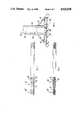
- FIGS. 1 and 2show, in side elevation and top plan view, cartridges of typical approximate actual size, as formed by injection moulding for use with an implant gun as described in our above-described co-pending Australian patent application PI 4456 (U.S. Ser. No. 246,344);
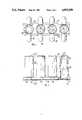
- FIG. 3is a view, in side elevation, of part of the cartridge of FIG. 1, on a scale of about 10:1;
- FIG. 4is a bottom plan view of the part cartridge of FIG. 3;
- FIG. 5is sectional view, taken on line V-V of FIG. 3.
- the cartridge 10 of FIGS. 1 and 2is formed by injection moulding low density polyethylene. Typically an end to end connected series of cartridges are formed simultaneously, part of a second cartridge 10' being shown in each of FIGS. 1 and 2. After moulding, the cartridges readily are able to be separated by rupturing the thin bridging elements 12 therebetween.
- Cartridge 10has a thin basal strip 14, from one face of which projects a series, typically of about 20 or 25, of pellet holders 16. To each side of each holder 16, strip 14 has a respective laterally projecting guide tab 18.
- holders 16are of hollow, substantially cylindrical form. However, each tapers slightly away from strip 14.
- each holder 16communicates with a respective opening 22 in strip 14; with each opening having a flared inlet 23 thereto.
- Cartridge 10is intended to hold two cylindrical pellets 24 in each holder 16. Such pellets 24 are shown in broken outline at the time of insertion into the holder 16 shown in section in FIG. 3. After the pellets 24 are inserted into each holder 16, openings 22 are closed by application of a thin, perforatable layer 26 of plastics film, metal foil, or a laminate material over bottom surface 28 of strip 14. Layer 26 is shown as if applied to surface 28 but, obviously, it is applied, such as by heat sealing or adhesive bonding, after insertion of the required pellets 24.
- the end of holders 16 remote from strip 14is configured to retain pellets 24 therein.
- a number of radially inwardly projecting protruberances 30are provided around cavity 20.
- the radial extent of protruberances 30is such that they prevent inadvertent passage of pellets 24, but enable the latter to be ejected by a moderate force.
- This arrangementis sufficient where the pellets do not require protection from air and/or moisture.
- a thin membranecan be provided across that remote end of cavity 20.
- Such membranecan be additional to, or instead of, protruberances 30.
- the membranecan be produced as part of cartridge 10 by injection moulding.
- the membranemay comprise a thin film or foil applied across the remote end of holders 16, such as by heat sealing an adhesive bonding.
- cartridge 10In use of cartridge 10 is an implant gun of our above-described co-pending application, it is inserted end-wise into a guideway 32 of a pellet discharge device, such as an implant gun as disclosed in our above-mentioned Australian patent application PI 4456 (U.S. Ser. No. 246344).
- guideway 32has a form somewhat complementary to that of the cartridge as shown in FIG. 5.
- the cartridgeis then indexed along the guideway 32, to present each holder and its pellet(s) in turn to a discharge position of such device.
- Guide tabs 18enagle such indexing under the action of an indexing means, such as a pair of ratchet wheels, engageable with tabs 18.
- Tabs 18assist is guiding cartridge 10 along guideway 32. However, they also facilitate bending of cartridge 10 around any curve in guideway 32 and, more importantly, they enable indexing means to engage cartridge 10 and to impart indexed, endwise movement to cartridge 10.
- the pelletscan be of a wide variety of forms. In one form, they are for implantation into or below animal tissue, and may comprise a variety of drugs, trace elements or like materials.
Landscapes
- Health & Medical Sciences (AREA)
- Engineering & Computer Science (AREA)
- Dermatology (AREA)
- Medical Informatics (AREA)
- Anesthesiology (AREA)
- Biomedical Technology (AREA)
- Heart & Thoracic Surgery (AREA)
- Hematology (AREA)
- Life Sciences & Earth Sciences (AREA)
- Animal Behavior & Ethology (AREA)
- General Health & Medical Sciences (AREA)
- Public Health (AREA)
- Veterinary Medicine (AREA)
- Infusion, Injection, And Reservoir Apparatuses (AREA)
- Materials For Medical Uses (AREA)
Abstract
Description
Claims (17)
Applications Claiming Priority (2)
| Application Number | Priority Date | Filing Date | Title |
|---|---|---|---|
| AUPI447387 | 1987-09-21 | ||
| AUPI4473 | 1987-09-21 |
Publications (1)
| Publication Number | Publication Date |
|---|---|
| US4925030Atrue US4925030A (en) | 1990-05-15 |
Family
ID=3772465
Family Applications (1)
| Application Number | Title | Priority Date | Filing Date |
|---|---|---|---|
| US07/246,345Expired - Fee RelatedUS4925030A (en) | 1987-09-21 | 1988-09-19 | Cartridge |
Country Status (3)
| Country | Link |
|---|---|
| US (1) | US4925030A (en) |
| AU (1) | AU616905B2 (en) |
| NZ (1) | NZ226256A (en) |
Cited By (5)
| Publication number | Priority date | Publication date | Assignee | Title |
|---|---|---|---|---|
| US5303620A (en)* | 1993-01-07 | 1994-04-19 | Payne Guy R | Screw gun |
| US6221003B1 (en) | 1999-07-26 | 2001-04-24 | Indigo Medical, Incorporated | Brachytherapy cartridge including absorbable and autoclaveable spacer |
| US20030098546A1 (en)* | 1999-12-09 | 2003-05-29 | Georges Beyssac | Support for storing , transporting and using devices applying a sealing compound and uses thereof |
| US6585633B2 (en) | 1999-07-26 | 2003-07-01 | C. R. Bard, Inc. | Brachytherapy seed cartridge |
| US9694968B2 (en)* | 2013-11-21 | 2017-07-04 | Rose Plastic Ag | Individual packaging for elongate objects |
Citations (14)
| Publication number | Priority date | Publication date | Assignee | Title |
|---|---|---|---|---|
| GB840276A (en)* | 1957-11-20 | 1960-07-06 | Arnold & Sons Veterinary Instr | Improvements in or relating to hypodermic implantation devices |
| US3153500A (en)* | 1961-11-20 | 1964-10-20 | Firearm Aceessories Inc | Gun cartridge holder |
| US3428169A (en)* | 1963-09-17 | 1969-02-18 | Fur Montage Technik Anstalt | Fastener and package therefor |
| US3693220A (en)* | 1967-02-13 | 1972-09-26 | Richard W Pabich | Wing headed fasteners and process for attaching same |
| US3812961A (en)* | 1972-04-24 | 1974-05-28 | Triad Fastener Corp | Screw package |
| US4106618A (en)* | 1975-12-15 | 1978-08-15 | Haytayan Harry M | Nail assemblies |
| US4154239A (en)* | 1976-05-18 | 1979-05-15 | Hundon Forge Limited | Drug pellet implanter |
| GB1583816A (en)* | 1978-05-22 | 1981-02-04 | Hundon Forge Ltd | Pellet magazine |
| EP0090899A1 (en)* | 1982-03-15 | 1983-10-12 | Eli Lilly And Company | Improvements in or relating to implant devices |
| US4531938A (en)* | 1983-07-06 | 1985-07-30 | Ivy-Gene Co., Inc. | Medicament implant applicator |
| US4560061A (en)* | 1983-09-13 | 1985-12-24 | Pneutek, Inc. | Powder charge feed strip |
| US4574954A (en)* | 1984-12-07 | 1986-03-11 | Medication Services Inc. | Pill dispenser |
| US4576591A (en)* | 1983-07-06 | 1986-03-18 | Ivy-Gene Co., Inc. | Medicament implant applicator |
| US4720374A (en)* | 1985-07-22 | 1988-01-19 | E. I. Du Pont De Nemours And Company | Container having a sonication compartment |
Family Cites Families (2)
| Publication number | Priority date | Publication date | Assignee | Title |
|---|---|---|---|---|
| US4447223A (en)* | 1982-04-16 | 1984-05-08 | Cct Associates | Medicament implant applicator |
| US4687465A (en)* | 1986-04-25 | 1987-08-18 | Ideal Instruments, Inc. | Automatic clip or pellet carrier fed pellet implanter apparatus |
- 1988
- 1988-09-19AUAU22429/88Apatent/AU616905B2/ennot_activeCeased
- 1988-09-19USUS07/246,345patent/US4925030A/ennot_activeExpired - Fee Related
- 1988-09-20NZNZ226256Apatent/NZ226256A/enunknown
Patent Citations (15)
| Publication number | Priority date | Publication date | Assignee | Title |
|---|---|---|---|---|
| GB840276A (en)* | 1957-11-20 | 1960-07-06 | Arnold & Sons Veterinary Instr | Improvements in or relating to hypodermic implantation devices |
| US3153500A (en)* | 1961-11-20 | 1964-10-20 | Firearm Aceessories Inc | Gun cartridge holder |
| US3428169A (en)* | 1963-09-17 | 1969-02-18 | Fur Montage Technik Anstalt | Fastener and package therefor |
| US3693220A (en)* | 1967-02-13 | 1972-09-26 | Richard W Pabich | Wing headed fasteners and process for attaching same |
| US3812961A (en)* | 1972-04-24 | 1974-05-28 | Triad Fastener Corp | Screw package |
| US4106618A (en)* | 1975-12-15 | 1978-08-15 | Haytayan Harry M | Nail assemblies |
| US4154239A (en)* | 1976-05-18 | 1979-05-15 | Hundon Forge Limited | Drug pellet implanter |
| GB1583816A (en)* | 1978-05-22 | 1981-02-04 | Hundon Forge Ltd | Pellet magazine |
| EP0090899A1 (en)* | 1982-03-15 | 1983-10-12 | Eli Lilly And Company | Improvements in or relating to implant devices |
| US4451254A (en)* | 1982-03-15 | 1984-05-29 | Eli Lilly And Company | Implant system |
| US4531938A (en)* | 1983-07-06 | 1985-07-30 | Ivy-Gene Co., Inc. | Medicament implant applicator |
| US4576591A (en)* | 1983-07-06 | 1986-03-18 | Ivy-Gene Co., Inc. | Medicament implant applicator |
| US4560061A (en)* | 1983-09-13 | 1985-12-24 | Pneutek, Inc. | Powder charge feed strip |
| US4574954A (en)* | 1984-12-07 | 1986-03-11 | Medication Services Inc. | Pill dispenser |
| US4720374A (en)* | 1985-07-22 | 1988-01-19 | E. I. Du Pont De Nemours And Company | Container having a sonication compartment |
Cited By (7)
| Publication number | Priority date | Publication date | Assignee | Title |
|---|---|---|---|---|
| US5303620A (en)* | 1993-01-07 | 1994-04-19 | Payne Guy R | Screw gun |
| US6221003B1 (en) | 1999-07-26 | 2001-04-24 | Indigo Medical, Incorporated | Brachytherapy cartridge including absorbable and autoclaveable spacer |
| US6585633B2 (en) | 1999-07-26 | 2003-07-01 | C. R. Bard, Inc. | Brachytherapy seed cartridge |
| US6648811B2 (en) | 1999-07-26 | 2003-11-18 | C.R. Bard, Inc. | Brachytherapy cartridge including absorbable and autoclaveable spacer |
| US20030098546A1 (en)* | 1999-12-09 | 2003-05-29 | Georges Beyssac | Support for storing , transporting and using devices applying a sealing compound and uses thereof |
| US7134666B2 (en)* | 1999-12-09 | 2006-11-14 | Le Joint Francais | Support for storing, transporting and using devices applying a sealing compound and uses thereof |
| US9694968B2 (en)* | 2013-11-21 | 2017-07-04 | Rose Plastic Ag | Individual packaging for elongate objects |
Also Published As
| Publication number | Publication date |
|---|---|
| AU616905B2 (en) | 1991-11-14 |
| AU2242988A (en) | 1989-04-13 |
| NZ226256A (en) | 1990-10-26 |
Similar Documents
| Publication | Publication Date | Title |
|---|---|---|
| US5366454A (en) | Implantable medication dispensing device | |
| US3351192A (en) | Package and retainer tray | |
| EP0308269A1 (en) | Cartridge for pellets | |
| KR960015180B1 (en) | Fluid injection method | |
| US4263910A (en) | Implantate package, system and method | |
| KR960015181B1 (en) | Fluid dispensing device with fluid supply cassette | |
| EP0529199B1 (en) | Sales and storage package for zinc/air batteries | |
| CA2459988A1 (en) | Thermoplastic polymer film sealing of nozzles on fluid ejection devices and method | |
| US4925030A (en) | Cartridge | |
| CA2243408A1 (en) | Sealing rubber closure for syringe/container | |
| DE3378966D1 (en) | Pressure pulse droplet ejector and array | |
| EP0288277A2 (en) | Cassette storing a plurality of electronic components | |
| KR960015182B1 (en) | Fluid injection system pumping method | |
| AU2429584A (en) | Storage bag | |
| EP0158612A3 (en) | A volume variable vessel | |
| HK102692A (en) | Holder for tape cartridges | |
| US5277530A (en) | Adhesively secured pump fastener system | |
| AU4842397A (en) | A material transfer apparatus | |
| US5767433A (en) | Component holder for cartridge reloading | |
| US6769567B2 (en) | Product dispenser | |
| ES293716U (en) | Egg container. | |
| US20200298575A1 (en) | Liquid storage container | |
| USD325218S (en) | Ink-jet cartridge | |
| USD254316S (en) | Ink cartridge with rupturable sealing element | |
| JPS5542882A (en) | Cartridge for recording head |
Legal Events
| Date | Code | Title | Description |
|---|---|---|---|
| AS | Assignment | Owner name:REGULIN LIMITED, LEVEL 12, 222 KINGSWAY, SOUTH MEL Free format text:ASSIGNMENT OF ASSIGNORS INTEREST.;ASSIGNOR:BALL, KEITH V.;REEL/FRAME:004975/0356 Effective date:19880916 Owner name:REGULIN LIMITED, A COMPANY OF SOUTH AUSTRALIA, AUS Free format text:ASSIGNMENT OF ASSIGNORS INTEREST;ASSIGNOR:BALL, KEITH V.;REEL/FRAME:004975/0356 Effective date:19880916 | |
| AS | Assignment | Owner name:SCHERING AGROCHEMICALS LIMITED, ENGLAND Free format text:ASSIGNMENT OF ASSIGNORS INTEREST.;ASSIGNOR:REGULIN LIMITED;REEL/FRAME:005139/0967 Effective date:19890426 | |
| CC | Certificate of correction | ||
| FEPP | Fee payment procedure | Free format text:PAYOR NUMBER ASSIGNED (ORIGINAL EVENT CODE: ASPN); ENTITY STATUS OF PATENT OWNER: LARGE ENTITY | |
| AS | Assignment | Owner name:HOECHST VETERINAER GMBH, GERMANY Free format text:ASSIGNMENT OF ASSIGNORS INTEREST;ASSIGNOR:SCHERING AGROCHEMICALS LIMITED;REEL/FRAME:006617/0378 Effective date:19920506 | |
| FPAY | Fee payment | Year of fee payment:4 | |
| FPAY | Fee payment | Year of fee payment:8 | |
| SULP | Surcharge for late payment | ||
| AS | Assignment | Owner name:SANOFI SANTE NUTRITION ANIMALE S.A., FRANCE Free format text:ASSIGNMENT OF ASSIGNORS INTEREST;ASSIGNOR:HOECHST ROUSSEL VET GMBH;REEL/FRAME:009445/0939 Effective date:19980811 | |
| FEPP | Fee payment procedure | Free format text:PAYER NUMBER DE-ASSIGNED (ORIGINAL EVENT CODE: RMPN); ENTITY STATUS OF PATENT OWNER: LARGE ENTITY Free format text:PAYOR NUMBER ASSIGNED (ORIGINAL EVENT CODE: ASPN); ENTITY STATUS OF PATENT OWNER: LARGE ENTITY | |
| REMI | Maintenance fee reminder mailed | ||
| LAPS | Lapse for failure to pay maintenance fees | ||
| STCH | Information on status: patent discontinuation | Free format text:PATENT EXPIRED DUE TO NONPAYMENT OF MAINTENANCE FEES UNDER 37 CFR 1.362 | |
| FP | Lapsed due to failure to pay maintenance fee | Effective date:20020515 |