US4924870A - Fiber optic sensors - Google Patents
Fiber optic sensorsDownload PDFInfo
- Publication number
- US4924870A US4924870AUS07/297,069US29706989AUS4924870AUS 4924870 AUS4924870 AUS 4924870AUS 29706989 AUS29706989 AUS 29706989AUS 4924870 AUS4924870 AUS 4924870A
- Authority
- US
- United States
- Prior art keywords
- sensing
- light
- fiber
- signal
- returned
- Prior art date
- Legal status (The legal status is an assumption and is not a legal conclusion. Google has not performed a legal analysis and makes no representation as to the accuracy of the status listed.)
- Expired - Lifetime
Links
Images


Classifications
- A—HUMAN NECESSITIES
- A61—MEDICAL OR VETERINARY SCIENCE; HYGIENE
- A61B—DIAGNOSIS; SURGERY; IDENTIFICATION
- A61B5/00—Measuring for diagnostic purposes; Identification of persons
- A61B5/02—Detecting, measuring or recording for evaluating the cardiovascular system, e.g. pulse, heart rate, blood pressure or blood flow
- A61B5/021—Measuring pressure in heart or blood vessels
- A61B5/0215—Measuring pressure in heart or blood vessels by means inserted into the body
- A61B5/02154—Measuring pressure in heart or blood vessels by means inserted into the body by optical transmission
- G—PHYSICS
- G01—MEASURING; TESTING
- G01L—MEASURING FORCE, STRESS, TORQUE, WORK, MECHANICAL POWER, MECHANICAL EFFICIENCY, OR FLUID PRESSURE
- G01L9/00—Measuring steady of quasi-steady pressure of fluid or fluent solid material by electric or magnetic pressure-sensitive elements; Transmitting or indicating the displacement of mechanical pressure-sensitive elements, used to measure the steady or quasi-steady pressure of a fluid or fluent solid material, by electric or magnetic means
- G01L9/0041—Transmitting or indicating the displacement of flexible diaphragms
- G01L9/0076—Transmitting or indicating the displacement of flexible diaphragms using photoelectric means
- G01L9/0077—Transmitting or indicating the displacement of flexible diaphragms using photoelectric means for measuring reflected light
Definitions
- the present inventionis related to a fiber optic sensing system and particularly to one enabling an environmental parameter to be sensed using a miniaturized sensing tip at one end of an optical fiber.
- Optical fiber sensing systemscan be used for a variety of applications.
- the measurement of intravascular blood pressure of human patientshas been accomplished using equipment manufactured by applicants in which a diaphragm at the fiber sensing tip deforms in response to a pressure differential and modulates light sent through the fiber in accordance with its deflection. Changes in the distance between the deformable diaphragm and the optical fiber tip changes the amplitude of light that is reflected back into the optical fiber. Accordingly, the intensity of the returned light is related to the sensed pressure.
- the catheteris placed in position and a precisely controlled pressure signal is applied through the fiber to one side of the diaphragm, which produces deflection of the diaphragm.
- the intensity of the returned lightis evaluated and used for calibration of the system. Thereafter, the measured intensity signal is compared to a software look-up table to generate an output indicating pressure at the sensing tip of the catheter.
- Optical fibers in general, and particularly low cost plastic and glass fibersexhibit a substantial change in light attenuation dependent upon their bending radius.
- dynamic bendingcan occur due to pressure pulses or movement of the fiber inside or outside of the patient.
- certain optical fiber couplersexhibit changes in their characteristics due to mechanical inputs during use.
- Other sources of measurement inaccuracy or noiseare the time dependent characteristics of the light sources and photodetectors (i.e., changes in intensity or sensitivity) which are used with such a measurement system.
- a fiber optic sensing systemis provided with a wavelength referencing feature which reduces measurement noise induced by bending sensitivity of the fibers, coupler changes, and thermal effects influencing the system.
- the systemincorporates a wavelength selective dielectric filter which is coated onto the sensing end of the optical fiber.
- the filterreflects back a reference or calibration optical signal while transmitting a sensing signal of a differing wavelength which is modulated in response to an environmental parameter and then reflected back into the fiber.
- the two signalsare separated and their intensity is measured. The ratio of the intensity of the two signals is used to provide a measure of the parameter being detected.
- both signalstraverse the entire optical length of the fiber and are perturbed in a similar manner by bending attenuation, couplers, etc.
- the ratio between these two signalsgenerates the appropriate output signal in response to the measuring modulation mechanism, essentially unaffected by such noise sources.
- light sources which produce the reference and sensing light beamsbehave similarly, changes in their output power with respect to time will be uniform and will also be self-correcting through the ratio measurement.
- a closed loop intensity control systemcan be used to equalize the light source outputs or compensate in some other manner for source intensity variations.
- a fiber optic measuring systemwhich generally provides the previously mentioned features is described by U.S. Pat. No. 4,356,396.
- systems for wavelength reference of a fiber optic sensing devices as exemplified by the above patentare known generally, such prior art devices have several significant drawbacks.
- the dielectric filter according to the prior art patentis a separate component which must be fabricated and attached to the sensing end of the fiber. This requirement would almost necessarily render the sensing tip more bulky than one without this feature.
- a dielectric wavelength selective filteris directly coated onto the fiber end through vapor deposition or other suitable techniques. Such a process enables a large number of fibers to be treated simultaneously and would not appreciably increase the size of the sensing tip.
- Another shortcoming of the prior art fiber optic sensing systems employing wavelength referencing described by the above patentis the fact that both light sources are operated simultaneously to generate a combined input signal which is fed through the optical fiber.
- the returned signalincludes both wavelengths which must be separated using a beam splitter and filters to provide signals for two discrete photodetectors.
- the requirement of a beam splitterreduces the intensity of the returned signal at the photodetector and, combined with the necessity of using wavelength selective filters, produces a low intensity signal incident on the photodetector.
- Such a systemis also vulnerable to changes in characteristics of each of the photodetectors during operation which is a source of measurement noise which is not compensated for by the dual wavelength referencing system of the prior art.
- time division multiplexingis used such that the differing wavelength light sources are operated alternately.
- a single photodetectoris used which is sensitive to both wavelengths and a synchronization signal is used to separate outputs generated by the two light sources. This approach reduces the complexity of the measurement system and renders it insensitive to additional sources of noise.
- the numerical aperture of the fiberis increased through the formation of a concave surface at the optical fiber sensing tip end.
- a concave surfaceincreases the cone angle of light emitted from the fiber (and the reception angle) which produces a greater change in returned light signal intensity in response to movement of the deformable membrane. Accordingly, the provision of such a concave surface enhances the sensitivity of the system.
- Another feature of this inventionis the provision of a beam separator which injects the input beam into the fiber and receives and focuses the returned light onto a photodetector.
- the separatoremploys an off-axis parabolic mirror with a central aperture through which the input beam passes.
- the returned beamis defocused to a large diameter which strikes the mirror and is focused onto the detector. This system provides excellent separation of the returned signal from the input signal.
- the wavelength referencing approachcan be used with fibers having variously shaped terminal ends (i.e., concave, flat, convex) for providing enhanced accuracy and resistance to measurement noise and can be used with various beam separators.
- the concave fiber end surfacecan be implemented with a bare fiber or one having a dielectric interference filter coating as a means of enhancing numerical aperture and therefore measurement sensitivity.
- the beam splitter arrangementmay likewise be used separately from the previously mentioned concepts and can be implemented in fiber optic sensors in which the returned signal is modulated in manners besides amplitude.
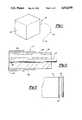
- FIG. 1is a pictorial view of a fiber optic sensing system in accordance with this invention particularly adapted for measurement of intravascular blood pressure.
- FIG. 2is an enlarged longitudinal cross-sectional view of a sensing tip for an optical fiber sensing system in accordance with the present invention.
- FIG. 3is an enlarged cutaway cross-sectional view taken from FIG. 2 illustrating multiple layers of dielectric material applied to the end surface of the optical filament which acts as a light wavelength selective filter.
- FIG. 4is a transmission versus wavelength spectrum for a pair of light sources used in the system according to this invention and showing the transmission characteristic of the interference filter shown in FIG. 2.
- FIG. 5is a diagrammatic illustration of a beam separator in accordance with this invention incorporating an off-axis parabolic mirror.
- FIG. 6is a schematic diagram of the electronic and optical elements of the detector unit of the optical fiber sensing system according to this invention which provides time division multiplexing for the reference and sensing light signals.
- FIG. 7is an enlarged cross-sectional view similar to FIG. 1 except showing another feature of the present invention in which the end of the optical filament is formed to a concave configuration.
- FIG. 8is a graph illustrating the relationship between the radius of curvature of the concave end of an optical filament versus the numerical aperture of the fiber.
- FIG. 9illustrates the relationship of returned light intensity versus the diaphragm's distance from an optical fiber core end for fibers having differing numerical apertures.
- FIG. 1provides a pictorial view of a fiber optic sensing system in accordance with this invention which is generally designated by reference number 10.
- System 10incorporates an elongated optical fiber 12 with a sensing tip 14 which modulates an input light signal to measure an environmental parameter such as fluid pressure.
- Detection unit 16houses the electronic and optical elements of the system.
- optical fiber 12 and sensing end 14would be disposable (i.e., single use) units.
- FIG. 2is a cross-sectional view of sensing tip end 14 of optical fiber 12.
- a single optical filament 18passes through ferrule 20 to which it is bonded or interference fit.
- Cylinder 22surrounds ferrule 20.
- Diaphragm cap 24is placed over cylinder 22 and has a center membrane portion 25 which deforms in response to variations in differential pressure across it.
- Input lightis sent through filament 18 and strikes the center area of membrane 25 and is reflected back into the fiber.
- a casing(not shown) encases and protects filament 18 and is connected to detection unit 16. The intensity of returned light is modulated by the separation between and fiber end surface 26.
- Detection unit 16provides the input light beam membrane 25, measures the intensity of the returned back signal and compares the intensity to an internal calibration table to output a pressure value.
- a vacuum signal of a known levelcan be applied to the inside surface of diaphragm cap 24 through the casing and vent passage 30 for calibration purposes.
- FIG. 3provides an enlarged view of the end surface 26 of filament 18 which incorporates a wavelength selective dielectric filter 34, showing the thickness of layers comprising the filter greatly enlarged for illustration.
- Filter 34is formed by depositing multiple layers of thin films of material of different indexes of refraction and specific thicknesses.
- dielectric filter 34comprises numerous layers, for example twenty layers, of titanium dioxide and silicone dioxide with the material alternating between layers. The layers comprising filter 34 are directly coated onto the filament ends by vapor deposition or other suitable processes. The presence of filter 34 does not complicate the process of assembling tip 14 or render it more bulky due to the minute thickness of the film.
- FIG. 4The spectral characteristics of filter 34 are graphically illustrated in FIG. 4.
- Curve 36illustrates that dielectric filter 34 provides a long wavelength pass characteristic with longer light being reflected back through filament 18. Longer wavelength light passes through filter 34 without significant attenuation.
- FIG. 4also illustrates the output spectra of a pair of light sources which may be used in implementing this invention.
- Curve 38is a light source such as an LED which emits light of a wavelength, for example, of 660 nanometers which would be reflected back by dielectric filter 34 and acts as a reference or calibration signal.
- the sensing light signalwhich may also be generated by an LED is represented by curve 40 and has a central output at about 820 nanometers which passes through dielectric filter 34.
- Light sources 42 and 44have output spectra within transmission windows of a plastic optical fiber material (i.e., spectral regions where transmission is high).
- the reference signalis reflected by dielectric filter 34 and is attenuated by the same sources of attenuation as the sensing signal. Differences in attenuation between the reference and sensing signals are caused by diaphragm position which affects only the sensing signal. By comparing the ratio of these two intensity levels of the returned signal, the modulated components of the sensing signal can be separated from noise sources.
- the modulation and noise source of both the reference and sensing signalscan be characterized as exponential:
- FIG. 5which illustrates a beam separator 68 in accordance with an aspect of this invention
- a pair of LED light sources 42 and 44are used to provide the relatively lower frequency reference signal (e.g., 660 nanometers) and the relatively shorter wavelength sensing signal (e.g., 820 nanometers), respectively.
- Lenses 43collimate the beams and apertures 45 limit beam diameter.
- Light outputted from LEDs 42 and 44are combined into a coaxial input beam 46 by planar beam splitter 48. Beam splitter 48 also directs a portion of the light from both LEDs 42 and 44 onto automatic intensity control photodetector 52 through focusing lens 50.
- Photodetector 52can be employed to either directly modulate the current applied to LEDs 42 and 44, or could be used to measure their output intensity to provide calibration of the returned signal.
- Lens 43 and aperture 45provide a narrow collimated beam 46 which passes through aperture 54 within parabolic mirror 56. The input beam 46 then passes through focusing lenses 58 and 60 where it is focused and injected into input end 62 of filament 18.
- the signal that is returned along fiber 12exits input end 62 at a dispersion or cone angle as illustrated in FIG. 5.
- This signalcan be comprised of light from a single light source or various sources as when the previously described wavelength referencing scheme is used.
- Lenses 58 and 60expand the returned beam and then collimate it such that it strikes parabolic mirror 56.
- the optical axis of mirror 56is tipped from beams 46 and 66 so that the returned light beam is focused onto photodetector 64.
- This systemprovides very high optical efficiency since the input signal is applied to fiber inlet end 62 without significant attenuation.
- the reflected back beamis expanded to a much greater diameter than the input beam, the only loss in intensity of the returned beam is attributable to the relatively small cross-sectional area defined by aperture 54, thus providing excellent signal strength at photodetector 64.
- LEDs 42 and 44are alternately energized in a pulsed fashion with a dwell period between pulses.
- photodetector 64detects the intensity of both the reference and sensing light signals and sorts the received signals through a synchronization signal from a controller to discriminate the intensity readings for both the reference and sensing signals.
- Photodetector 52is employed for an intensity control system to control the current applied to LEDs 42 and 44 to provide a desired output intensity.
- photodetector 64would directly sense and output a signal related to returned light intensity without requiring synchronization with the source.
- FIG. 6provides a block diagram of the electronic and optical components of detection unit 16 with the beam separator 68 of FIG. 5 removed for clarity.
- Reference signal generator 72provides triggering signals for the entire system and controls the time division multiplexing operation. Triggering signals are applied to reference signal LED 42 and sensing signal LED 44, respectively, through LED drivers 74 and 76.
- Photodetector 52provides a signal for intensity control or calibration and receives a timing signal from generator 72 to enable it to distinguish between light from sources 42 and 44.
- Sample-and-hold circuits 78 and 80provide appropriate synchronization to allow the light and dark currents to be measured from intensity control photodetector 52. In other words, the sample-and-hold circuits allow sampling of photodetector current after a light pulse is received and before the next pulse arrives.
- the signals that are returned along filament 18are sensed by photodetector 64.
- Signal separator 84is a switching network synchronized by reference signal generator 72 to permit separation of the returned beam 66 from LED sources 42 and 44 from each other. Accordingly, returned light from reference LED 42 produces an attenuation reference signal 86, and returned light from sensing LED 44 produces diaphragm deflection signal 88.
- Sample-and-hold circuits 90 and 92are employed to provide a memory or time delay so that the intensities of these signals can be directly compared at the same time by radiometric compensator or comparator 94 and measures dark current in the same way as photodetector 52.
- Comparator 94provides an output 96 which is fed through appropriate signal processing electronics, for example, as described by applicants' previously issued U.S. Pat. No. 4,711,246 to provide an output of the parameter being measured.
- end 26 of filament 18is formed with a concave surface 108.
- the concave surfaceis hemispherical in shape and has a radius of curvature shown by radius line 102.
- the provision of such a concave surfaceincreases the numerical aperture of fiber assembly 12.
- the relationship between the radius of curvature of concave end 108 and the resulting numerical apertureis illustrated in FIG. 8.
- substantial increases in numerical apertureare provided, particularly when the radius of curvature is below about 300 microns.
- a radius of curvature of 276 micronswas used which provided a 0.8 numerical aperture.
- Enhancements in numerical apertureincrease the cone angle of light emitted from (and received by) fiber end 26. This characteristic has been shown to increase the sensitivity of the system to changes in deflection or distance of diaphragm membrane 25 from the fiber end. This characteristic is illustrated graphically by FIG. 9.
- Curve 104illustrates the relationship between diaphragm displacement and reflectance for a fiber having a relatively low numerical aperture of 0.5, for example.
- Curve 106shows this relationship for a fiber having a 0.8 numerical aperture. The slopes of curves 104 and 106 determine the sensitivity of the system.
- Concave end surface 108can be formed by machining processes and perhaps also by direct molding or heat melting. Moreover, the concave surface could also be formed by a separate lens which would be bonded to fiber end 26.
Landscapes
- Health & Medical Sciences (AREA)
- Life Sciences & Earth Sciences (AREA)
- Physics & Mathematics (AREA)
- Cardiology (AREA)
- Biomedical Technology (AREA)
- Molecular Biology (AREA)
- Vascular Medicine (AREA)
- Biophysics (AREA)
- Pathology (AREA)
- Engineering & Computer Science (AREA)
- General Physics & Mathematics (AREA)
- Heart & Thoracic Surgery (AREA)
- Medical Informatics (AREA)
- Physiology (AREA)
- Surgery (AREA)
- Animal Behavior & Ethology (AREA)
- General Health & Medical Sciences (AREA)
- Public Health (AREA)
- Veterinary Medicine (AREA)
- Measuring Fluid Pressure (AREA)
- Investigating Or Analysing Materials By Optical Means (AREA)
Abstract
Description
S=s exp [-n(t)] R=r exp [-n(t)-x(t)]
x(t)=log S/R
Claims (18)
Priority Applications (2)
| Application Number | Priority Date | Filing Date | Title |
|---|---|---|---|
| US07/297,069US4924870A (en) | 1989-01-13 | 1989-01-13 | Fiber optic sensors |
| EP90301111AEP0439887A1 (en) | 1989-01-13 | 1990-02-02 | Improved fiber optic sensors |
Applications Claiming Priority (1)
| Application Number | Priority Date | Filing Date | Title |
|---|---|---|---|
| US07/297,069US4924870A (en) | 1989-01-13 | 1989-01-13 | Fiber optic sensors |
Publications (1)
| Publication Number | Publication Date |
|---|---|
| US4924870Atrue US4924870A (en) | 1990-05-15 |
Family
ID=23144729
Family Applications (1)
| Application Number | Title | Priority Date | Filing Date |
|---|---|---|---|
| US07/297,069Expired - LifetimeUS4924870A (en) | 1989-01-13 | 1989-01-13 | Fiber optic sensors |
Country Status (2)
| Country | Link |
|---|---|
| US (1) | US4924870A (en) |
| EP (1) | EP0439887A1 (en) |
Cited By (106)
| Publication number | Priority date | Publication date | Assignee | Title |
|---|---|---|---|---|
| WO1991012767A1 (en)* | 1990-02-26 | 1991-09-05 | Baxter International Inc. | Intracranial pressure monitoring system |
| US5094958A (en)* | 1990-08-30 | 1992-03-10 | Fiberchem Inc. | Method of self-compensating a fiber optic chemical sensor |
| EP0528657A3 (en)* | 1991-08-21 | 1993-05-26 | Fiberoptic Sensor Technologies, Inc. | Improved fiber optic pressure sensor systems |
| US5247171A (en)* | 1992-04-17 | 1993-09-21 | Fiberoptic Sensor Technologies, Inc. | Drift correction for fiberoptic pressure sensors |
| US5275038A (en)* | 1991-05-20 | 1994-01-04 | Otis Engineering Corporation | Downhole reeled tubing inspection system with fiberoptic cable |
| US5313957A (en)* | 1990-01-05 | 1994-05-24 | Medamicus, Inc. | Guide wire mounted pressure transducer |
| US5390546A (en)* | 1993-07-01 | 1995-02-21 | Wlodarczyk; Marek T. | Fiber optic diaphragm sensors for engine knock and misfire detection |
| US5419188A (en)* | 1991-05-20 | 1995-05-30 | Otis Engineering Corporation | Reeled tubing support for downhole equipment module |
| US5422478A (en)* | 1992-04-17 | 1995-06-06 | Fiberoptic Sensor Technologies, Inc. | Fiberoptic pressure sensor having drift correction means for insitu calibration |
| US5427114A (en)* | 1993-08-19 | 1995-06-27 | Fiberoptic Sensor Technologies, Inc. | Dual pressure sensing catheter |
| US5485741A (en)* | 1993-10-19 | 1996-01-23 | Medamicus, Inc. | Vacuum calibration method for an optical fiber pressure transducer |
| WO1996036276A1 (en)* | 1995-05-15 | 1996-11-21 | The University Of Sydney | Optical fibre filter sensor |
| US5654539A (en)* | 1995-08-17 | 1997-08-05 | Vasamedics L.L.C. | Laser doppler optical sensor for use on a monitoring probe |
| WO1998017988A1 (en)* | 1996-10-23 | 1998-04-30 | Optrand, Inc. | Integrated fiber optic combustion pressure sensor |
| US5747793A (en)* | 1995-10-04 | 1998-05-05 | Advanced Fiber Optechs, Inc. | Variable light source compensated optical fiber sensing system |
| US5987995A (en)* | 1997-07-17 | 1999-11-23 | Sentec Corporation | Fiber optic pressure catheter |
| WO2000079233A1 (en)* | 1999-06-18 | 2000-12-28 | Samba Sensors Ab | A method and a device for bending compensation in intensity-based fibre-optical measuring systems |
| US6321010B1 (en)* | 1999-08-30 | 2001-11-20 | Lucent Technologies Inc. | Optical microstructure and method of manufacture |
| US6604427B1 (en) | 1999-07-19 | 2003-08-12 | Nate Coleman | Bellow-type pressure sensing apparatus |
| US20050019217A1 (en)* | 2001-09-14 | 2005-01-27 | Michael Sander | Analytical equipment for determining the chemical structure and/or composition of a plurality of samples and sample holder |
| US20050252663A1 (en)* | 2004-05-17 | 2005-11-17 | Olson Mark P | Fiber-optic based automatic fire-suppression controller |
| US20060011820A1 (en)* | 2004-07-16 | 2006-01-19 | Kin-Man Yip And Chow-Shing Shin | Fiber-optic sensing system |
| US20070259381A1 (en)* | 2006-02-21 | 2007-11-08 | The Trustees Of Tufts College | Methods and arrays for target analyte detection and determination of reaction components that affect a reaction |
| US20080221408A1 (en)* | 2007-03-09 | 2008-09-11 | Nellcor Puritan Bennett Llc | System and methods for optical sensing and drug delivery using microneedles |
| US20090027659A1 (en)* | 1999-06-18 | 2009-01-29 | Sambra Sensors Ab | Measuring system for measuring a physical parameter influencing a sensor element |
| US20100075439A1 (en)* | 2008-09-23 | 2010-03-25 | Quanterix Corporation | Ultra-sensitive detection of molecules by capture-and-release using reducing agents followed by quantification |
| US20100075407A1 (en)* | 2008-09-23 | 2010-03-25 | Quanterix Corporation | Ultra-sensitive detection of molecules on single molecule arrays |
| US20100075862A1 (en)* | 2008-09-23 | 2010-03-25 | Quanterix Corporation | High sensitivity determination of the concentration of analyte molecules or particles in a fluid sample |
| US7713196B2 (en) | 2007-03-09 | 2010-05-11 | Nellcor Puritan Bennett Llc | Method for evaluating skin hydration and fluid compartmentalization |
| US7794407B2 (en) | 2006-10-23 | 2010-09-14 | Bard Access Systems, Inc. | Method of locating the tip of a central venous catheter |
| US20100249550A1 (en)* | 2009-03-25 | 2010-09-30 | Neilcor Puritan Bennett LLC | Method And Apparatus For Optical Filtering Of A Broadband Emitter In A Medical Sensor |
| US20110212537A1 (en)* | 2010-03-01 | 2011-09-01 | Quanterix Corporation | Methods and systems for extending dynamic range in assays for the detection of molecules or particles |
| US20110212848A1 (en)* | 2010-03-01 | 2011-09-01 | Quanterix Corporation | Ultra-sensitive detection of molecules or particles using beads or other capture objects |
| US20110212462A1 (en)* | 2010-03-01 | 2011-09-01 | Quanterix Corporation | Ultra-sensitive detection of molecules using dual detection methods |
| US20120021455A1 (en)* | 2010-07-20 | 2012-01-26 | Biomerieux, Inc. | Detector Arrangement for Blood Culture Bottles With Colorimetric Sensors |
| US8388541B2 (en) | 2007-11-26 | 2013-03-05 | C. R. Bard, Inc. | Integrated system for intravascular placement of a catheter |
| US8388546B2 (en) | 2006-10-23 | 2013-03-05 | Bard Access Systems, Inc. | Method of locating the tip of a central venous catheter |
| US8424617B2 (en) | 2008-08-20 | 2013-04-23 | Foro Energy Inc. | Methods and apparatus for delivering high power laser energy to a surface |
| US8437833B2 (en) | 2008-10-07 | 2013-05-07 | Bard Access Systems, Inc. | Percutaneous magnetic gastrostomy |
| US8478382B2 (en) | 2008-02-11 | 2013-07-02 | C. R. Bard, Inc. | Systems and methods for positioning a catheter |
| EP2610659A1 (en) | 2011-12-27 | 2013-07-03 | Huawei Technologies Co., Ltd. | Optical path coupling device, optical path coupling apparatus and optical path coupling method |
| WO2013109267A1 (en)* | 2012-01-18 | 2013-07-25 | Biomerieux, Inc. | Detector arrangement for blood culture bottles with colorimetric sensors |
| US8571368B2 (en) | 2010-07-21 | 2013-10-29 | Foro Energy, Inc. | Optical fiber configurations for transmission of laser energy over great distances |
| US8627901B1 (en) | 2009-10-01 | 2014-01-14 | Foro Energy, Inc. | Laser bottom hole assembly |
| JP2014007057A (en)* | 2012-06-25 | 2014-01-16 | Olympus Corp | Light source device |
| USD699359S1 (en) | 2011-08-09 | 2014-02-11 | C. R. Bard, Inc. | Ultrasound probe head |
| US8662160B2 (en) | 2008-08-20 | 2014-03-04 | Foro Energy Inc. | Systems and conveyance structures for high power long distance laser transmission |
| US8781555B2 (en) | 2007-11-26 | 2014-07-15 | C. R. Bard, Inc. | System for placement of a catheter including a signal-generating stylet |
| US8784336B2 (en) | 2005-08-24 | 2014-07-22 | C. R. Bard, Inc. | Stylet apparatuses and methods of manufacture |
| US8801693B2 (en) | 2010-10-29 | 2014-08-12 | C. R. Bard, Inc. | Bioimpedance-assisted placement of a medical device |
| US8849382B2 (en) | 2007-11-26 | 2014-09-30 | C. R. Bard, Inc. | Apparatus and display methods relating to intravascular placement of a catheter |
| US20150005736A1 (en)* | 2011-09-07 | 2015-01-01 | Asante Solutions, Inc. | Occlusion Detection for an Infusion Pump System |
| USD724745S1 (en) | 2011-08-09 | 2015-03-17 | C. R. Bard, Inc. | Cap for an ultrasound probe |
| US20150124336A1 (en)* | 2013-06-25 | 2015-05-07 | Public Service Solutions, Inc. | Wide spectrum optical systems and devices implementing first surface mirrors |
| US9027668B2 (en) | 2008-08-20 | 2015-05-12 | Foro Energy, Inc. | Control system for high power laser drilling workover and completion unit |
| US9074422B2 (en) | 2011-02-24 | 2015-07-07 | Foro Energy, Inc. | Electric motor for laser-mechanical drilling |
| US9080425B2 (en) | 2008-10-17 | 2015-07-14 | Foro Energy, Inc. | High power laser photo-conversion assemblies, apparatuses and methods of use |
| US9089928B2 (en) | 2008-08-20 | 2015-07-28 | Foro Energy, Inc. | Laser systems and methods for the removal of structures |
| US9110025B2 (en) | 2010-03-01 | 2015-08-18 | Quanterix Corporation | Methods and systems for extending dynamic range in assays for the detection of molecules or particles |
| US9125578B2 (en) | 2009-06-12 | 2015-09-08 | Bard Access Systems, Inc. | Apparatus and method for catheter navigation and tip location |
| US9138786B2 (en) | 2008-10-17 | 2015-09-22 | Foro Energy, Inc. | High power laser pipeline tool and methods of use |
| US9211107B2 (en) | 2011-11-07 | 2015-12-15 | C. R. Bard, Inc. | Ruggedized ultrasound hydrogel insert |
| US9242309B2 (en) | 2012-03-01 | 2016-01-26 | Foro Energy Inc. | Total internal reflection laser tools and methods |
| US9244235B2 (en) | 2008-10-17 | 2016-01-26 | Foro Energy, Inc. | Systems and assemblies for transferring high power laser energy through a rotating junction |
| US9267330B2 (en) | 2008-08-20 | 2016-02-23 | Foro Energy, Inc. | Long distance high power optical laser fiber break detection and continuity monitoring systems and methods |
| US9339206B2 (en) | 2009-06-12 | 2016-05-17 | Bard Access Systems, Inc. | Adaptor for endovascular electrocardiography |
| US9347271B2 (en) | 2008-10-17 | 2016-05-24 | Foro Energy, Inc. | Optical fiber cable for transmission of high power laser energy over great distances |
| US9360643B2 (en) | 2011-06-03 | 2016-06-07 | Foro Energy, Inc. | Rugged passively cooled high power laser fiber optic connectors and methods of use |
| US9360631B2 (en) | 2008-08-20 | 2016-06-07 | Foro Energy, Inc. | Optics assembly for high power laser tools |
| US9445734B2 (en) | 2009-06-12 | 2016-09-20 | Bard Access Systems, Inc. | Devices and methods for endovascular electrography |
| US9456766B2 (en) | 2007-11-26 | 2016-10-04 | C. R. Bard, Inc. | Apparatus for use with needle insertion guidance system |
| US9492097B2 (en) | 2007-11-26 | 2016-11-15 | C. R. Bard, Inc. | Needle length determination and calibration for insertion guidance system |
| US9521961B2 (en) | 2007-11-26 | 2016-12-20 | C. R. Bard, Inc. | Systems and methods for guiding a medical instrument |
| US9532724B2 (en) | 2009-06-12 | 2017-01-03 | Bard Access Systems, Inc. | Apparatus and method for catheter navigation using endovascular energy mapping |
| US9554716B2 (en) | 2007-11-26 | 2017-01-31 | C. R. Bard, Inc. | Insertion guidance system for needles and medical components |
| US9562395B2 (en) | 2008-08-20 | 2017-02-07 | Foro Energy, Inc. | High power laser-mechanical drilling bit and methods of use |
| US20170065225A1 (en)* | 2015-09-04 | 2017-03-09 | Boston Scientific Scimed, Inc. | Pressure sensing guidewires |
| US9636031B2 (en) | 2007-11-26 | 2017-05-02 | C.R. Bard, Inc. | Stylets for use with apparatus for intravascular placement of a catheter |
| US9649048B2 (en) | 2007-11-26 | 2017-05-16 | C. R. Bard, Inc. | Systems and methods for breaching a sterile field for intravascular placement of a catheter |
| US9664012B2 (en) | 2008-08-20 | 2017-05-30 | Foro Energy, Inc. | High power laser decomissioning of multistring and damaged wells |
| US9669492B2 (en) | 2008-08-20 | 2017-06-06 | Foro Energy, Inc. | High power laser offshore decommissioning tool, system and methods of use |
| US9719302B2 (en) | 2008-08-20 | 2017-08-01 | Foro Energy, Inc. | High power laser perforating and laser fracturing tools and methods of use |
| US20170284862A1 (en)* | 2016-03-31 | 2017-10-05 | Fuji Jukogyo Kabushiki Kaisha | Optical observation system and optical observation method |
| US9809838B2 (en) | 2007-08-30 | 2017-11-07 | Trustees Of Tufts College | Methods for determining the concentration of an analyte in solution |
| US9839372B2 (en) | 2014-02-06 | 2017-12-12 | C. R. Bard, Inc. | Systems and methods for guidance and placement of an intravascular device |
| US9901714B2 (en) | 2008-08-22 | 2018-02-27 | C. R. Bard, Inc. | Catheter assembly including ECG sensor and magnetic assemblies |
| US9932626B2 (en) | 2013-01-15 | 2018-04-03 | Quanterix Corporation | Detection of DNA or RNA using single molecule arrays and other techniques |
| US9952237B2 (en) | 2011-01-28 | 2018-04-24 | Quanterix Corporation | Systems, devices, and methods for ultra-sensitive detection of molecules or particles |
| US10046139B2 (en) | 2010-08-20 | 2018-08-14 | C. R. Bard, Inc. | Reconfirmation of ECG-assisted catheter tip placement |
| US10221687B2 (en) | 2015-11-26 | 2019-03-05 | Merger Mines Corporation | Method of mining using a laser |
| US10301912B2 (en)* | 2008-08-20 | 2019-05-28 | Foro Energy, Inc. | High power laser flow assurance systems, tools and methods |
| US10349890B2 (en) | 2015-06-26 | 2019-07-16 | C. R. Bard, Inc. | Connector interface for ECG-based catheter positioning system |
| US10393759B2 (en) | 2011-04-12 | 2019-08-27 | Quanterix Corporation | Methods of determining a treatment protocol for and/or a prognosis of a patient's recovery from a brain injury |
| US20190277724A1 (en)* | 2018-03-09 | 2019-09-12 | Viavi Solutions Inc. | Mult-wavelength pulsed optical test instrument |
| US20190290207A1 (en)* | 2018-03-23 | 2019-09-26 | Boston Scientific Scimed, Inc. | Medical device with pressure sensor |
| US10449330B2 (en) | 2007-11-26 | 2019-10-22 | C. R. Bard, Inc. | Magnetic element-equipped needle assemblies |
| US10524691B2 (en) | 2007-11-26 | 2020-01-07 | C. R. Bard, Inc. | Needle assembly including an aligned magnetic element |
| US10639008B2 (en) | 2009-10-08 | 2020-05-05 | C. R. Bard, Inc. | Support and cover structures for an ultrasound probe head |
| US10751509B2 (en) | 2007-11-26 | 2020-08-25 | C. R. Bard, Inc. | Iconic representations for guidance of an indwelling medical device |
| US10820885B2 (en) | 2012-06-15 | 2020-11-03 | C. R. Bard, Inc. | Apparatus and methods for detection of a removable cap on an ultrasound probe |
| US10973584B2 (en) | 2015-01-19 | 2021-04-13 | Bard Access Systems, Inc. | Device and method for vascular access |
| US10992079B2 (en) | 2018-10-16 | 2021-04-27 | Bard Access Systems, Inc. | Safety-equipped connection systems and methods thereof for establishing electrical connections |
| US11000207B2 (en) | 2016-01-29 | 2021-05-11 | C. R. Bard, Inc. | Multiple coil system for tracking a medical device |
| US11103213B2 (en) | 2009-10-08 | 2021-08-31 | C. R. Bard, Inc. | Spacers for use with an ultrasound probe |
| US11237171B2 (en) | 2006-02-21 | 2022-02-01 | Trustees Of Tufts College | Methods and arrays for target analyte detection and determination of target analyte concentration in solution |
| US20240019296A1 (en)* | 2022-07-12 | 2024-01-18 | Interdisciplinary Consulting Corporation | Readout circuits for amplitude modulating sensors |
Families Citing this family (1)
| Publication number | Priority date | Publication date | Assignee | Title |
|---|---|---|---|---|
| US6252689B1 (en) | 1998-04-10 | 2001-06-26 | Aircuity, Inc. | Networked photonic signal distribution system |
Citations (7)
| Publication number | Priority date | Publication date | Assignee | Title |
|---|---|---|---|---|
| US4588294A (en)* | 1984-06-27 | 1986-05-13 | Warner-Lambert Technologies, Inc. | Searching and measuring endoscope |
| US4593701A (en)* | 1984-04-16 | 1986-06-10 | Hitachi Cable, Ltd. | Catheter-tip micromanometer utilizing single polarization optical fiber |
| US4691709A (en)* | 1986-07-01 | 1987-09-08 | Cordis Corporation | Apparatus for measuring velocity of blood flow in a blood vessel |
| US4703757A (en)* | 1984-11-16 | 1987-11-03 | Cordis Corporation | Optical fiber pressure transducer |
| US4711246A (en)* | 1986-09-02 | 1987-12-08 | Fiberoptic Sensor Technologies, Inc. | Fiber optic coupled pressure transducer using single fiber and method of fabrication |
| US4730622A (en)* | 1986-07-01 | 1988-03-15 | Cordis Corporation | Pressure and oxygen saturation catheter |
| US4787396A (en)* | 1987-06-18 | 1988-11-29 | Fiberoptic Sensor Technologies, Inc. | Fiberoptic pressure transducer |
Family Cites Families (4)
| Publication number | Priority date | Publication date | Assignee | Title |
|---|---|---|---|---|
| SE7903175L (en)* | 1979-04-10 | 1980-10-11 | Asea Ab | FIBEROPTICAL METDON |
| DE3709253A1 (en)* | 1987-03-20 | 1988-09-29 | Fraunhofer Ges Forschung | Fabry Perot sensor |
| DE8802025U1 (en)* | 1988-02-17 | 1988-03-31 | Fibronix Faseroptische Sensoren + Systeme GmbH, 2300 Kiel | Pressure sensor |
| IT1216609B (en)* | 1988-04-21 | 1990-03-08 | Pirelli Cavi Spa | OPTICAL POSITION SENSOR. |
- 1989
- 1989-01-13USUS07/297,069patent/US4924870A/ennot_activeExpired - Lifetime
- 1990
- 1990-02-02EPEP90301111Apatent/EP0439887A1/ennot_activeWithdrawn
Patent Citations (7)
| Publication number | Priority date | Publication date | Assignee | Title |
|---|---|---|---|---|
| US4593701A (en)* | 1984-04-16 | 1986-06-10 | Hitachi Cable, Ltd. | Catheter-tip micromanometer utilizing single polarization optical fiber |
| US4588294A (en)* | 1984-06-27 | 1986-05-13 | Warner-Lambert Technologies, Inc. | Searching and measuring endoscope |
| US4703757A (en)* | 1984-11-16 | 1987-11-03 | Cordis Corporation | Optical fiber pressure transducer |
| US4691709A (en)* | 1986-07-01 | 1987-09-08 | Cordis Corporation | Apparatus for measuring velocity of blood flow in a blood vessel |
| US4730622A (en)* | 1986-07-01 | 1988-03-15 | Cordis Corporation | Pressure and oxygen saturation catheter |
| US4711246A (en)* | 1986-09-02 | 1987-12-08 | Fiberoptic Sensor Technologies, Inc. | Fiber optic coupled pressure transducer using single fiber and method of fabrication |
| US4787396A (en)* | 1987-06-18 | 1988-11-29 | Fiberoptic Sensor Technologies, Inc. | Fiberoptic pressure transducer |
Cited By (208)
| Publication number | Priority date | Publication date | Assignee | Title |
|---|---|---|---|---|
| US5313957A (en)* | 1990-01-05 | 1994-05-24 | Medamicus, Inc. | Guide wire mounted pressure transducer |
| US5325865A (en)* | 1990-02-26 | 1994-07-05 | Baxter International, Inc. | Intracranial pressure monitoring system |
| WO1991012767A1 (en)* | 1990-02-26 | 1991-09-05 | Baxter International Inc. | Intracranial pressure monitoring system |
| US5094958A (en)* | 1990-08-30 | 1992-03-10 | Fiberchem Inc. | Method of self-compensating a fiber optic chemical sensor |
| US5419188A (en)* | 1991-05-20 | 1995-05-30 | Otis Engineering Corporation | Reeled tubing support for downhole equipment module |
| US5275038A (en)* | 1991-05-20 | 1994-01-04 | Otis Engineering Corporation | Downhole reeled tubing inspection system with fiberoptic cable |
| EP0528657A3 (en)* | 1991-08-21 | 1993-05-26 | Fiberoptic Sensor Technologies, Inc. | Improved fiber optic pressure sensor systems |
| US5275053A (en)* | 1991-08-21 | 1994-01-04 | Fiberoptic Sensor Technologies, Inc. | Fiber optic pressure sensor systems |
| US5385053A (en)* | 1991-08-21 | 1995-01-31 | Fiberoptic Sensor Technologies | Fiber optic pressure sensor systems |
| WO1993021652A1 (en)* | 1992-04-17 | 1993-10-28 | Fiberoptic Sensor Technologies, Inc. | Drift correction for fiberoptic pressure sensors |
| US5422478A (en)* | 1992-04-17 | 1995-06-06 | Fiberoptic Sensor Technologies, Inc. | Fiberoptic pressure sensor having drift correction means for insitu calibration |
| US5247171A (en)* | 1992-04-17 | 1993-09-21 | Fiberoptic Sensor Technologies, Inc. | Drift correction for fiberoptic pressure sensors |
| US5390546A (en)* | 1993-07-01 | 1995-02-21 | Wlodarczyk; Marek T. | Fiber optic diaphragm sensors for engine knock and misfire detection |
| US5427114A (en)* | 1993-08-19 | 1995-06-27 | Fiberoptic Sensor Technologies, Inc. | Dual pressure sensing catheter |
| US5485741A (en)* | 1993-10-19 | 1996-01-23 | Medamicus, Inc. | Vacuum calibration method for an optical fiber pressure transducer |
| WO1996036276A1 (en)* | 1995-05-15 | 1996-11-21 | The University Of Sydney | Optical fibre filter sensor |
| US5654539A (en)* | 1995-08-17 | 1997-08-05 | Vasamedics L.L.C. | Laser doppler optical sensor for use on a monitoring probe |
| US5747793A (en)* | 1995-10-04 | 1998-05-05 | Advanced Fiber Optechs, Inc. | Variable light source compensated optical fiber sensing system |
| WO1998017988A1 (en)* | 1996-10-23 | 1998-04-30 | Optrand, Inc. | Integrated fiber optic combustion pressure sensor |
| US5987995A (en)* | 1997-07-17 | 1999-11-23 | Sentec Corporation | Fiber optic pressure catheter |
| WO2000079233A1 (en)* | 1999-06-18 | 2000-12-28 | Samba Sensors Ab | A method and a device for bending compensation in intensity-based fibre-optical measuring systems |
| US6934015B1 (en) | 1999-06-18 | 2005-08-23 | Samba Sensors Ab | Method and a device for bending compensation in intensity-based fibre-optical measuring systems |
| US20050243308A1 (en)* | 1999-06-18 | 2005-11-03 | Samba Sensors Ab | Method and a device for bending compensation in intensity-based fibre-optical measuring systems |
| US20090027659A1 (en)* | 1999-06-18 | 2009-01-29 | Sambra Sensors Ab | Measuring system for measuring a physical parameter influencing a sensor element |
| US6604427B1 (en) | 1999-07-19 | 2003-08-12 | Nate Coleman | Bellow-type pressure sensing apparatus |
| US6321010B1 (en)* | 1999-08-30 | 2001-11-20 | Lucent Technologies Inc. | Optical microstructure and method of manufacture |
| US20050019217A1 (en)* | 2001-09-14 | 2005-01-27 | Michael Sander | Analytical equipment for determining the chemical structure and/or composition of a plurality of samples and sample holder |
| US7591322B2 (en) | 2004-05-17 | 2009-09-22 | Mark Petrus Olson | Fiber-optic based automatic fire-suppression controller |
| US20050252663A1 (en)* | 2004-05-17 | 2005-11-17 | Olson Mark P | Fiber-optic based automatic fire-suppression controller |
| US7196318B2 (en) | 2004-07-16 | 2007-03-27 | Kin-Man Yip | Fiber-optic sensing system |
| US20060011820A1 (en)* | 2004-07-16 | 2006-01-19 | Kin-Man Yip And Chow-Shing Shin | Fiber-optic sensing system |
| US8784336B2 (en) | 2005-08-24 | 2014-07-22 | C. R. Bard, Inc. | Stylet apparatuses and methods of manufacture |
| US10004875B2 (en) | 2005-08-24 | 2018-06-26 | C. R. Bard, Inc. | Stylet apparatuses and methods of manufacture |
| US11207496B2 (en) | 2005-08-24 | 2021-12-28 | C. R. Bard, Inc. | Stylet apparatuses and methods of manufacture |
| US8492098B2 (en) | 2006-02-21 | 2013-07-23 | The Trustees Of Tufts College | Methods and arrays for target analyte detection and determination of reaction components that affect a reaction |
| US9395359B2 (en) | 2006-02-21 | 2016-07-19 | Trustees Of Tufts College | Methods and arrays for target analyte detection and determination of target analyte concentration in solution |
| US11237171B2 (en) | 2006-02-21 | 2022-02-01 | Trustees Of Tufts College | Methods and arrays for target analyte detection and determination of target analyte concentration in solution |
| US8460878B2 (en) | 2006-02-21 | 2013-06-11 | The Trustees Of Tufts College | Methods and arrays for detecting cells and cellular components in small defined volumes |
| US8460879B2 (en) | 2006-02-21 | 2013-06-11 | The Trustees Of Tufts College | Methods and arrays for target analyte detection and determination of target analyte concentration in solution |
| US20070259381A1 (en)* | 2006-02-21 | 2007-11-08 | The Trustees Of Tufts College | Methods and arrays for target analyte detection and determination of reaction components that affect a reaction |
| US10261089B2 (en) | 2006-02-21 | 2019-04-16 | Trustees Of Tufts College | Methods and arrays for target analyte detection and determination of target analyte concentration in solution |
| US20070259448A1 (en)* | 2006-02-21 | 2007-11-08 | The Trustees Of Tufts College | Methods and arrays for target analyte detection and determination of target analyte concentration in solution |
| US20070259385A1 (en)* | 2006-02-21 | 2007-11-08 | The Trustees Of Tufts College | Methods and arrays for detecting cells and cellular components in small defined volumes |
| US11874279B2 (en) | 2006-02-21 | 2024-01-16 | Trustees Of Tufts College | Methods and arrays for target analyte detection and determination of target analyte concentration in solution |
| US9833169B2 (en) | 2006-10-23 | 2017-12-05 | Bard Access Systems, Inc. | Method of locating the tip of a central venous catheter |
| US9345422B2 (en) | 2006-10-23 | 2016-05-24 | Bard Acess Systems, Inc. | Method of locating the tip of a central venous catheter |
| US9265443B2 (en) | 2006-10-23 | 2016-02-23 | Bard Access Systems, Inc. | Method of locating the tip of a central venous catheter |
| US8388546B2 (en) | 2006-10-23 | 2013-03-05 | Bard Access Systems, Inc. | Method of locating the tip of a central venous catheter |
| US8858455B2 (en) | 2006-10-23 | 2014-10-14 | Bard Access Systems, Inc. | Method of locating the tip of a central venous catheter |
| US7794407B2 (en) | 2006-10-23 | 2010-09-14 | Bard Access Systems, Inc. | Method of locating the tip of a central venous catheter |
| US8774907B2 (en) | 2006-10-23 | 2014-07-08 | Bard Access Systems, Inc. | Method of locating the tip of a central venous catheter |
| US8512256B2 (en) | 2006-10-23 | 2013-08-20 | Bard Access Systems, Inc. | Method of locating the tip of a central venous catheter |
| US7713196B2 (en) | 2007-03-09 | 2010-05-11 | Nellcor Puritan Bennett Llc | Method for evaluating skin hydration and fluid compartmentalization |
| US20080221408A1 (en)* | 2007-03-09 | 2008-09-11 | Nellcor Puritan Bennett Llc | System and methods for optical sensing and drug delivery using microneedles |
| US8560059B2 (en) | 2007-03-09 | 2013-10-15 | Covidien Lp | System and methods for optical sensing and drug delivery using microneedles |
| US9809838B2 (en) | 2007-08-30 | 2017-11-07 | Trustees Of Tufts College | Methods for determining the concentration of an analyte in solution |
| US10238418B2 (en) | 2007-11-26 | 2019-03-26 | C. R. Bard, Inc. | Apparatus for use with needle insertion guidance system |
| US9526440B2 (en) | 2007-11-26 | 2016-12-27 | C.R. Bard, Inc. | System for placement of a catheter including a signal-generating stylet |
| US9999371B2 (en) | 2007-11-26 | 2018-06-19 | C. R. Bard, Inc. | Integrated system for intravascular placement of a catheter |
| US9681823B2 (en) | 2007-11-26 | 2017-06-20 | C. R. Bard, Inc. | Integrated system for intravascular placement of a catheter |
| US8388541B2 (en) | 2007-11-26 | 2013-03-05 | C. R. Bard, Inc. | Integrated system for intravascular placement of a catheter |
| US10105121B2 (en) | 2007-11-26 | 2018-10-23 | C. R. Bard, Inc. | System for placement of a catheter including a signal-generating stylet |
| US9649048B2 (en) | 2007-11-26 | 2017-05-16 | C. R. Bard, Inc. | Systems and methods for breaching a sterile field for intravascular placement of a catheter |
| US11779240B2 (en) | 2007-11-26 | 2023-10-10 | C. R. Bard, Inc. | Systems and methods for breaching a sterile field for intravascular placement of a catheter |
| US9636031B2 (en) | 2007-11-26 | 2017-05-02 | C.R. Bard, Inc. | Stylets for use with apparatus for intravascular placement of a catheter |
| US11707205B2 (en) | 2007-11-26 | 2023-07-25 | C. R. Bard, Inc. | Integrated system for intravascular placement of a catheter |
| US10165962B2 (en) | 2007-11-26 | 2019-01-01 | C. R. Bard, Inc. | Integrated systems for intravascular placement of a catheter |
| US9554716B2 (en) | 2007-11-26 | 2017-01-31 | C. R. Bard, Inc. | Insertion guidance system for needles and medical components |
| US10231753B2 (en) | 2007-11-26 | 2019-03-19 | C. R. Bard, Inc. | Insertion guidance system for needles and medical components |
| US9549685B2 (en) | 2007-11-26 | 2017-01-24 | C. R. Bard, Inc. | Apparatus and display methods relating to intravascular placement of a catheter |
| US8781555B2 (en) | 2007-11-26 | 2014-07-15 | C. R. Bard, Inc. | System for placement of a catheter including a signal-generating stylet |
| US10966630B2 (en) | 2007-11-26 | 2021-04-06 | C. R. Bard, Inc. | Integrated system for intravascular placement of a catheter |
| US11529070B2 (en) | 2007-11-26 | 2022-12-20 | C. R. Bard, Inc. | System and methods for guiding a medical instrument |
| US9521961B2 (en) | 2007-11-26 | 2016-12-20 | C. R. Bard, Inc. | Systems and methods for guiding a medical instrument |
| US9492097B2 (en) | 2007-11-26 | 2016-11-15 | C. R. Bard, Inc. | Needle length determination and calibration for insertion guidance system |
| US9456766B2 (en) | 2007-11-26 | 2016-10-04 | C. R. Bard, Inc. | Apparatus for use with needle insertion guidance system |
| US8849382B2 (en) | 2007-11-26 | 2014-09-30 | C. R. Bard, Inc. | Apparatus and display methods relating to intravascular placement of a catheter |
| US10342575B2 (en) | 2007-11-26 | 2019-07-09 | C. R. Bard, Inc. | Apparatus for use with needle insertion guidance system |
| US10449330B2 (en) | 2007-11-26 | 2019-10-22 | C. R. Bard, Inc. | Magnetic element-equipped needle assemblies |
| US10524691B2 (en) | 2007-11-26 | 2020-01-07 | C. R. Bard, Inc. | Needle assembly including an aligned magnetic element |
| US10602958B2 (en) | 2007-11-26 | 2020-03-31 | C. R. Bard, Inc. | Systems and methods for guiding a medical instrument |
| US11134915B2 (en) | 2007-11-26 | 2021-10-05 | C. R. Bard, Inc. | System for placement of a catheter including a signal-generating stylet |
| US10751509B2 (en) | 2007-11-26 | 2020-08-25 | C. R. Bard, Inc. | Iconic representations for guidance of an indwelling medical device |
| US10849695B2 (en) | 2007-11-26 | 2020-12-01 | C. R. Bard, Inc. | Systems and methods for breaching a sterile field for intravascular placement of a catheter |
| US11123099B2 (en) | 2007-11-26 | 2021-09-21 | C. R. Bard, Inc. | Apparatus for use with needle insertion guidance system |
| US8971994B2 (en) | 2008-02-11 | 2015-03-03 | C. R. Bard, Inc. | Systems and methods for positioning a catheter |
| US8478382B2 (en) | 2008-02-11 | 2013-07-02 | C. R. Bard, Inc. | Systems and methods for positioning a catheter |
| US9267330B2 (en) | 2008-08-20 | 2016-02-23 | Foro Energy, Inc. | Long distance high power optical laser fiber break detection and continuity monitoring systems and methods |
| US9562395B2 (en) | 2008-08-20 | 2017-02-07 | Foro Energy, Inc. | High power laser-mechanical drilling bit and methods of use |
| US10036232B2 (en) | 2008-08-20 | 2018-07-31 | Foro Energy | Systems and conveyance structures for high power long distance laser transmission |
| US9089928B2 (en) | 2008-08-20 | 2015-07-28 | Foro Energy, Inc. | Laser systems and methods for the removal of structures |
| US9719302B2 (en) | 2008-08-20 | 2017-08-01 | Foro Energy, Inc. | High power laser perforating and laser fracturing tools and methods of use |
| US8511401B2 (en) | 2008-08-20 | 2013-08-20 | Foro Energy, Inc. | Method and apparatus for delivering high power laser energy over long distances |
| US9669492B2 (en) | 2008-08-20 | 2017-06-06 | Foro Energy, Inc. | High power laser offshore decommissioning tool, system and methods of use |
| US9027668B2 (en) | 2008-08-20 | 2015-05-12 | Foro Energy, Inc. | Control system for high power laser drilling workover and completion unit |
| US9664012B2 (en) | 2008-08-20 | 2017-05-30 | Foro Energy, Inc. | High power laser decomissioning of multistring and damaged wells |
| US8636085B2 (en) | 2008-08-20 | 2014-01-28 | Foro Energy, Inc. | Methods and apparatus for removal and control of material in laser drilling of a borehole |
| US8662160B2 (en) | 2008-08-20 | 2014-03-04 | Foro Energy Inc. | Systems and conveyance structures for high power long distance laser transmission |
| US11060378B2 (en)* | 2008-08-20 | 2021-07-13 | Foro Energy, Inc. | High power laser flow assurance systems, tools and methods |
| US8997894B2 (en) | 2008-08-20 | 2015-04-07 | Foro Energy, Inc. | Method and apparatus for delivering high power laser energy over long distances |
| US9284783B1 (en) | 2008-08-20 | 2016-03-15 | Foro Energy, Inc. | High power laser energy distribution patterns, apparatus and methods for creating wells |
| US8936108B2 (en) | 2008-08-20 | 2015-01-20 | Foro Energy, Inc. | High power laser downhole cutting tools and systems |
| US8701794B2 (en) | 2008-08-20 | 2014-04-22 | Foro Energy, Inc. | High power laser perforating tools and systems |
| US8757292B2 (en) | 2008-08-20 | 2014-06-24 | Foro Energy, Inc. | Methods for enhancing the efficiency of creating a borehole using high power laser systems |
| US8424617B2 (en) | 2008-08-20 | 2013-04-23 | Foro Energy Inc. | Methods and apparatus for delivering high power laser energy to a surface |
| US8820434B2 (en) | 2008-08-20 | 2014-09-02 | Foro Energy, Inc. | Apparatus for advancing a wellbore using high power laser energy |
| US8826973B2 (en) | 2008-08-20 | 2014-09-09 | Foro Energy, Inc. | Method and system for advancement of a borehole using a high power laser |
| US8869914B2 (en) | 2008-08-20 | 2014-10-28 | Foro Energy, Inc. | High power laser workover and completion tools and systems |
| US9360631B2 (en) | 2008-08-20 | 2016-06-07 | Foro Energy, Inc. | Optics assembly for high power laser tools |
| US10301912B2 (en)* | 2008-08-20 | 2019-05-28 | Foro Energy, Inc. | High power laser flow assurance systems, tools and methods |
| US11027101B2 (en) | 2008-08-22 | 2021-06-08 | C. R. Bard, Inc. | Catheter assembly including ECG sensor and magnetic assemblies |
| US9901714B2 (en) | 2008-08-22 | 2018-02-27 | C. R. Bard, Inc. | Catheter assembly including ECG sensor and magnetic assemblies |
| US20100075407A1 (en)* | 2008-09-23 | 2010-03-25 | Quanterix Corporation | Ultra-sensitive detection of molecules on single molecule arrays |
| US8222047B2 (en) | 2008-09-23 | 2012-07-17 | Quanterix Corporation | Ultra-sensitive detection of molecules on single molecule arrays |
| US8846415B2 (en) | 2008-09-23 | 2014-09-30 | Quanterix Corporation | Ultra-sensitive detection of molecules on single molecule arrays |
| US20100075862A1 (en)* | 2008-09-23 | 2010-03-25 | Quanterix Corporation | High sensitivity determination of the concentration of analyte molecules or particles in a fluid sample |
| US20100075439A1 (en)* | 2008-09-23 | 2010-03-25 | Quanterix Corporation | Ultra-sensitive detection of molecules by capture-and-release using reducing agents followed by quantification |
| US9907513B2 (en) | 2008-10-07 | 2018-03-06 | Bard Access Systems, Inc. | Percutaneous magnetic gastrostomy |
| US8437833B2 (en) | 2008-10-07 | 2013-05-07 | Bard Access Systems, Inc. | Percutaneous magnetic gastrostomy |
| US9080425B2 (en) | 2008-10-17 | 2015-07-14 | Foro Energy, Inc. | High power laser photo-conversion assemblies, apparatuses and methods of use |
| US9347271B2 (en) | 2008-10-17 | 2016-05-24 | Foro Energy, Inc. | Optical fiber cable for transmission of high power laser energy over great distances |
| US9138786B2 (en) | 2008-10-17 | 2015-09-22 | Foro Energy, Inc. | High power laser pipeline tool and methods of use |
| US9327810B2 (en) | 2008-10-17 | 2016-05-03 | Foro Energy, Inc. | High power laser ROV systems and methods for treating subsea structures |
| US9244235B2 (en) | 2008-10-17 | 2016-01-26 | Foro Energy, Inc. | Systems and assemblies for transferring high power laser energy through a rotating junction |
| US20100249550A1 (en)* | 2009-03-25 | 2010-09-30 | Neilcor Puritan Bennett LLC | Method And Apparatus For Optical Filtering Of A Broadband Emitter In A Medical Sensor |
| US10231643B2 (en) | 2009-06-12 | 2019-03-19 | Bard Access Systems, Inc. | Apparatus and method for catheter navigation and tip location |
| US10912488B2 (en) | 2009-06-12 | 2021-02-09 | Bard Access Systems, Inc. | Apparatus and method for catheter navigation and tip location |
| US9532724B2 (en) | 2009-06-12 | 2017-01-03 | Bard Access Systems, Inc. | Apparatus and method for catheter navigation using endovascular energy mapping |
| US9339206B2 (en) | 2009-06-12 | 2016-05-17 | Bard Access Systems, Inc. | Adaptor for endovascular electrocardiography |
| US9125578B2 (en) | 2009-06-12 | 2015-09-08 | Bard Access Systems, Inc. | Apparatus and method for catheter navigation and tip location |
| US10271762B2 (en) | 2009-06-12 | 2019-04-30 | Bard Access Systems, Inc. | Apparatus and method for catheter navigation using endovascular energy mapping |
| US11419517B2 (en) | 2009-06-12 | 2022-08-23 | Bard Access Systems, Inc. | Apparatus and method for catheter navigation using endovascular energy mapping |
| US9445734B2 (en) | 2009-06-12 | 2016-09-20 | Bard Access Systems, Inc. | Devices and methods for endovascular electrography |
| US8627901B1 (en) | 2009-10-01 | 2014-01-14 | Foro Energy, Inc. | Laser bottom hole assembly |
| US11103213B2 (en) | 2009-10-08 | 2021-08-31 | C. R. Bard, Inc. | Spacers for use with an ultrasound probe |
| US10639008B2 (en) | 2009-10-08 | 2020-05-05 | C. R. Bard, Inc. | Support and cover structures for an ultrasound probe head |
| US11998386B2 (en) | 2009-10-08 | 2024-06-04 | C. R. Bard, Inc. | Support and cover structures for an ultrasound probe head |
| US10725032B2 (en) | 2010-03-01 | 2020-07-28 | Quanterix Corporation | Ultra-sensitive detection of molecules or particles using beads or other capture objects |
| US20110212848A1 (en)* | 2010-03-01 | 2011-09-01 | Quanterix Corporation | Ultra-sensitive detection of molecules or particles using beads or other capture objects |
| US12235267B2 (en) | 2010-03-01 | 2025-02-25 | Quanterix Corporation | Ultra-sensitive detection of molecules or particles using beads or other capture objects |
| US9846155B2 (en) | 2010-03-01 | 2017-12-19 | Quanterix Corporation | Methods and systems for extending dynamic range in assays for the detection of molecules or particles |
| US20110212537A1 (en)* | 2010-03-01 | 2011-09-01 | Quanterix Corporation | Methods and systems for extending dynamic range in assays for the detection of molecules or particles |
| US12019072B2 (en) | 2010-03-01 | 2024-06-25 | Quanterix Corporation | Methods and systems for extending dynamic range in assays for the detection of molecules or particles |
| US11619631B2 (en) | 2010-03-01 | 2023-04-04 | Quanterix Corporation | Ultra-sensitive detection of molecules or particles using beads or other capture objects |
| US8415171B2 (en) | 2010-03-01 | 2013-04-09 | Quanterix Corporation | Methods and systems for extending dynamic range in assays for the detection of molecules or particles |
| US20110212462A1 (en)* | 2010-03-01 | 2011-09-01 | Quanterix Corporation | Ultra-sensitive detection of molecules using dual detection methods |
| US9482662B2 (en) | 2010-03-01 | 2016-11-01 | Quanterix Corporation | Ultra-sensitive detection of molecules or particles using beads or other capture objects |
| US9551663B2 (en) | 2010-03-01 | 2017-01-24 | Quanterix Corporation | Methods and systems for extending dynamic range in assays for the detection of molecules or particles |
| US9110025B2 (en) | 2010-03-01 | 2015-08-18 | Quanterix Corporation | Methods and systems for extending dynamic range in assays for the detection of molecules or particles |
| US9678068B2 (en) | 2010-03-01 | 2017-06-13 | Quanterix Corporation | Ultra-sensitive detection of molecules using dual detection methods |
| US10989713B2 (en) | 2010-03-01 | 2021-04-27 | Quanterix Corporation | Methods and systems for extending dynamic range in assays for the detection of molecules or particles |
| US9310360B2 (en) | 2010-03-01 | 2016-04-12 | Quanterix Corporation | Ultra-sensitive detection of molecules or particles using beads or other capture objects |
| US8236574B2 (en) | 2010-03-01 | 2012-08-07 | Quanterix Corporation | Ultra-sensitive detection of molecules or particles using beads or other capture objects |
| US9447372B2 (en) | 2010-07-20 | 2016-09-20 | Biomerieux, Inc. | Detector arrangement for blood culture bottles with colorimetric sensors |
| US9739788B2 (en)* | 2010-07-20 | 2017-08-22 | Biomerieux, Inc. | Detector arrangement for blood culture bottles with colorimetric sensors |
| US20120021455A1 (en)* | 2010-07-20 | 2012-01-26 | Biomerieux, Inc. | Detector Arrangement for Blood Culture Bottles With Colorimetric Sensors |
| US8879876B2 (en) | 2010-07-21 | 2014-11-04 | Foro Energy, Inc. | Optical fiber configurations for transmission of laser energy over great distances |
| US8571368B2 (en) | 2010-07-21 | 2013-10-29 | Foro Energy, Inc. | Optical fiber configurations for transmission of laser energy over great distances |
| US10046139B2 (en) | 2010-08-20 | 2018-08-14 | C. R. Bard, Inc. | Reconfirmation of ECG-assisted catheter tip placement |
| US8801693B2 (en) | 2010-10-29 | 2014-08-12 | C. R. Bard, Inc. | Bioimpedance-assisted placement of a medical device |
| US9415188B2 (en) | 2010-10-29 | 2016-08-16 | C. R. Bard, Inc. | Bioimpedance-assisted placement of a medical device |
| US11977087B2 (en) | 2011-01-28 | 2024-05-07 | Quanterix Corporation | Systems, devices, and methods for ultra-sensitive detection of molecules or particles |
| US11112415B2 (en) | 2011-01-28 | 2021-09-07 | Quanterix Corporation | Systems, devices, and methods for ultra-sensitive detection of molecules or particles |
| US9952237B2 (en) | 2011-01-28 | 2018-04-24 | Quanterix Corporation | Systems, devices, and methods for ultra-sensitive detection of molecules or particles |
| US9784037B2 (en) | 2011-02-24 | 2017-10-10 | Daryl L. Grubb | Electric motor for laser-mechanical drilling |
| US9074422B2 (en) | 2011-02-24 | 2015-07-07 | Foro Energy, Inc. | Electric motor for laser-mechanical drilling |
| US10393759B2 (en) | 2011-04-12 | 2019-08-27 | Quanterix Corporation | Methods of determining a treatment protocol for and/or a prognosis of a patient's recovery from a brain injury |
| US11275092B2 (en) | 2011-04-12 | 2022-03-15 | Quanterix Corporation | Methods of determining a treatment protocol for and/or a prognosis of a patient's recovery from a brain injury |
| US9360643B2 (en) | 2011-06-03 | 2016-06-07 | Foro Energy, Inc. | Rugged passively cooled high power laser fiber optic connectors and methods of use |
| USD754357S1 (en) | 2011-08-09 | 2016-04-19 | C. R. Bard, Inc. | Ultrasound probe head |
| USD724745S1 (en) | 2011-08-09 | 2015-03-17 | C. R. Bard, Inc. | Cap for an ultrasound probe |
| USD699359S1 (en) | 2011-08-09 | 2014-02-11 | C. R. Bard, Inc. | Ultrasound probe head |
| US9610404B2 (en)* | 2011-09-07 | 2017-04-04 | Bigfoot Biomedical, Inc. | Method for occlusion detection for an infusion pump system |
| US20150005736A1 (en)* | 2011-09-07 | 2015-01-01 | Asante Solutions, Inc. | Occlusion Detection for an Infusion Pump System |
| US9211107B2 (en) | 2011-11-07 | 2015-12-15 | C. R. Bard, Inc. | Ruggedized ultrasound hydrogel insert |
| EP2610659A1 (en) | 2011-12-27 | 2013-07-03 | Huawei Technologies Co., Ltd. | Optical path coupling device, optical path coupling apparatus and optical path coupling method |
| CN104053991A (en)* | 2012-01-18 | 2014-09-17 | 生物梅里埃有限公司 | Detector arrangement for blood culture bottles with colorimetric sensors |
| CN104053991B (en)* | 2012-01-18 | 2016-09-14 | 生物梅里埃有限公司 | For having the detector means of the Blood culture bottle of colorimetric sensor |
| WO2013109267A1 (en)* | 2012-01-18 | 2013-07-25 | Biomerieux, Inc. | Detector arrangement for blood culture bottles with colorimetric sensors |
| US9242309B2 (en) | 2012-03-01 | 2016-01-26 | Foro Energy Inc. | Total internal reflection laser tools and methods |
| US10820885B2 (en) | 2012-06-15 | 2020-11-03 | C. R. Bard, Inc. | Apparatus and methods for detection of a removable cap on an ultrasound probe |
| EP2865936A4 (en)* | 2012-06-25 | 2016-02-24 | Olympus Corp | Light source device |
| JP2014007057A (en)* | 2012-06-25 | 2014-01-16 | Olympus Corp | Light source device |
| US9482870B2 (en) | 2012-06-25 | 2016-11-01 | Olympus Corporation | Light source apparatus |
| US10640814B2 (en) | 2013-01-15 | 2020-05-05 | Quanterix Corporation | Detection of DNA or RNA using single molecule arrays and other techniques |
| US9932626B2 (en) | 2013-01-15 | 2018-04-03 | Quanterix Corporation | Detection of DNA or RNA using single molecule arrays and other techniques |
| US20150124336A1 (en)* | 2013-06-25 | 2015-05-07 | Public Service Solutions, Inc. | Wide spectrum optical systems and devices implementing first surface mirrors |
| US10863920B2 (en) | 2014-02-06 | 2020-12-15 | C. R. Bard, Inc. | Systems and methods for guidance and placement of an intravascular device |
| US9839372B2 (en) | 2014-02-06 | 2017-12-12 | C. R. Bard, Inc. | Systems and methods for guidance and placement of an intravascular device |
| US10973584B2 (en) | 2015-01-19 | 2021-04-13 | Bard Access Systems, Inc. | Device and method for vascular access |
| US11026630B2 (en) | 2015-06-26 | 2021-06-08 | C. R. Bard, Inc. | Connector interface for ECG-based catheter positioning system |
| US10349890B2 (en) | 2015-06-26 | 2019-07-16 | C. R. Bard, Inc. | Connector interface for ECG-based catheter positioning system |
| US11857345B2 (en)* | 2015-09-04 | 2024-01-02 | Boston Scientific Scimed, Inc. | Pressure sensing guidewires |
| US20170065225A1 (en)* | 2015-09-04 | 2017-03-09 | Boston Scientific Scimed, Inc. | Pressure sensing guidewires |
| JP2018532452A (en)* | 2015-09-04 | 2018-11-08 | ボストン サイエンティフィック サイムド,インコーポレイテッドBoston Scientific Scimed,Inc. | Pressure sensing guidewire |
| US10221687B2 (en) | 2015-11-26 | 2019-03-05 | Merger Mines Corporation | Method of mining using a laser |
| US11000207B2 (en) | 2016-01-29 | 2021-05-11 | C. R. Bard, Inc. | Multiple coil system for tracking a medical device |
| US10996103B2 (en)* | 2016-03-31 | 2021-05-04 | Subaru Corporation | Optical observation system and optical observation method |
| US20170284862A1 (en)* | 2016-03-31 | 2017-10-05 | Fuji Jukogyo Kabushiki Kaisha | Optical observation system and optical observation method |
| US11467059B2 (en) | 2018-03-09 | 2022-10-11 | Viavi Solutions Inc. | Multi-wavelength pulsed optical test instrument |
| US20190277724A1 (en)* | 2018-03-09 | 2019-09-12 | Viavi Solutions Inc. | Mult-wavelength pulsed optical test instrument |
| US10801918B2 (en)* | 2018-03-09 | 2020-10-13 | Viavi Solutions Inc. | Mult-wavelength pulsed optical test instrument |
| US20190290207A1 (en)* | 2018-03-23 | 2019-09-26 | Boston Scientific Scimed, Inc. | Medical device with pressure sensor |
| US11850073B2 (en)* | 2018-03-23 | 2023-12-26 | Boston Scientific Scimed, Inc. | Medical device with pressure sensor |
| US11621518B2 (en) | 2018-10-16 | 2023-04-04 | Bard Access Systems, Inc. | Safety-equipped connection systems and methods thereof for establishing electrical connections |
| US10992079B2 (en) | 2018-10-16 | 2021-04-27 | Bard Access Systems, Inc. | Safety-equipped connection systems and methods thereof for establishing electrical connections |
| US20240019296A1 (en)* | 2022-07-12 | 2024-01-18 | Interdisciplinary Consulting Corporation | Readout circuits for amplitude modulating sensors |
| US12276543B2 (en)* | 2022-07-12 | 2025-04-15 | Interdisciplinary Consulting Corporation | Readout circuits for amplitude modulating sensors |
Also Published As
| Publication number | Publication date |
|---|---|
| EP0439887A1 (en) | 1991-08-07 |
Similar Documents
| Publication | Publication Date | Title |
|---|---|---|
| US4924870A (en) | Fiber optic sensors | |
| US4487206A (en) | Fiber optic pressure sensor with temperature compensation and reference | |
| CA2086338C (en) | Process and device for determining measured quantities by means of an integrated optical sensor module | |
| US4986671A (en) | Three-parameter optical fiber sensor and system | |
| US4356396A (en) | Fiber optical measuring device with compensating properties | |
| US5275053A (en) | Fiber optic pressure sensor systems | |
| US4790669A (en) | Spectroscopic method and apparatus for optically measuring temperature | |
| US4342919A (en) | Fiber optical measuring device | |
| US4883062A (en) | Temperture and pressure monitors utilizing interference filters | |
| US7060965B2 (en) | Method and device for fibre-optical measuring systems | |
| US4408123A (en) | Fiber optical sensor device for measuring a physical parameter | |
| US4572669A (en) | Method and apparatus for a Fabry-Perot multiple beam fringe sensor | |
| EP0168960B1 (en) | Optical displacement sensors | |
| US4647203A (en) | Fiber optic sensor | |
| US4714829A (en) | Fibre optic sensing device and method | |
| US4430565A (en) | Correlating fiber optical measuring device | |
| GB2130719A (en) | Fibre-optic thermometer | |
| US5131062A (en) | Fiber optic sensor module | |
| US5418361A (en) | Optical displacement sensor employing reflected light of four wavelengths to determine displacement and the refractive index of the medium | |
| JPH07107566B2 (en) | Optical fiber optical sensor device | |
| CA2009226A1 (en) | Fiber optic sensors | |
| GB2183821A (en) | A temperature sensor | |
| US4947038A (en) | Process and arrangement for optically measuring a physical quantity | |
| US4861980A (en) | Optical sensor having stationary co-terminus ends of the input and output optical fibres | |
| US5345076A (en) | Optically trimmed sensor for reducing influence of differential node losses |
Legal Events
| Date | Code | Title | Description |
|---|---|---|---|
| AS | Assignment | Owner name:FIBEROPTIC SENSOR TECHNOLOGIES, INC., A MI CORP., Free format text:ASSIGNMENT OF ASSIGNORS INTEREST.;ASSIGNORS:WLODARCZYK, MAREK T.;COLETTA, LUCIANO;CAMPBELL, JAMES A.;AND OTHERS;REEL/FRAME:005019/0776 Effective date:19890113 | |
| STCF | Information on status: patent grant | Free format text:PATENTED CASE | |
| FEPP | Fee payment procedure | Free format text:PAYOR NUMBER ASSIGNED (ORIGINAL EVENT CODE: ASPN); ENTITY STATUS OF PATENT OWNER: LARGE ENTITY | |
| FPAY | Fee payment | Year of fee payment:4 | |
| AS | Assignment | Owner name:BARD ACQUISITION COMPANY, INC., MICHIGAN Free format text:ASSIGNMENT OF ASSIGNORS INTEREST;ASSIGNOR:FIBER-OPTEC SENSOR TECHNOLOGIES, INC.;REEL/FRAME:007505/0610 Effective date:19950602 | |
| FEPP | Fee payment procedure | Free format text:PAT HLDR NO LONGER CLAIMS SMALL ENT STAT AS SMALL BUSINESS (ORIGINAL EVENT CODE: LSM2); ENTITY STATUS OF PATENT OWNER: LARGE ENTITY | |
| AS | Assignment | Owner name:BARD FIBEROPTIC TECHNOLOGIES, INC., MICHIGAN Free format text:CHANGE OF NAME;ASSIGNOR:BARD ACQUISITION COMPANY, INC.;REEL/FRAME:008209/0639 Effective date:19951204 Owner name:C.R. BARD, INC., NEW JERSEY Free format text:ASSIGNMENT OF ASSIGNORS INTEREST;ASSIGNOR:BARD FIBEROPTIC TECHNOLOGIES, INC.;REEL/FRAME:008209/0573 Effective date:19960919 | |
| FPAY | Fee payment | Year of fee payment:8 | |
| FEPP | Fee payment procedure | Free format text:PAYER NUMBER DE-ASSIGNED (ORIGINAL EVENT CODE: RMPN); ENTITY STATUS OF PATENT OWNER: LARGE ENTITY Free format text:PAYOR NUMBER ASSIGNED (ORIGINAL EVENT CODE: ASPN); ENTITY STATUS OF PATENT OWNER: LARGE ENTITY | |
| FPAY | Fee payment | Year of fee payment:12 |