US4924739A - Method and apparatus for producing a contact lens - Google Patents
Method and apparatus for producing a contact lensDownload PDFInfo
- Publication number
- US4924739A US4924739AUS06/623,361US62336184AUS4924739AUS 4924739 AUS4924739 AUS 4924739AUS 62336184 AUS62336184 AUS 62336184AUS 4924739 AUS4924739 AUS 4924739A
- Authority
- US
- United States
- Prior art keywords
- mold
- collet
- lens
- spindle
- conical
- Prior art date
- Legal status (The legal status is an assumption and is not a legal conclusion. Google has not performed a legal analysis and makes no representation as to the accuracy of the status listed.)
- Expired - Lifetime
Links
- 238000000034methodMethods0.000titleclaimsdescription12
- 238000003754machiningMethods0.000claimsabstractdescription14
- 230000003247decreasing effectEffects0.000claims1
- 239000000463materialSubstances0.000abstractdescription18
- 230000003287optical effectEffects0.000abstractdescription13
- 230000000295complement effectEffects0.000abstract1
- 230000008878couplingEffects0.000description7
- 238000010168coupling processMethods0.000description7
- 238000005859coupling reactionMethods0.000description7
- 238000005520cutting processMethods0.000description6
- 238000004519manufacturing processMethods0.000description6
- 238000001746injection mouldingMethods0.000description3
- 238000005266castingMethods0.000description2
- 238000005498polishingMethods0.000description2
- 238000006116polymerization reactionMethods0.000description2
- 230000004075alterationEffects0.000description1
- 238000004873anchoringMethods0.000description1
- 150000001875compoundsChemical class0.000description1
- 238000007688edgingMethods0.000description1
- 238000002347injectionMethods0.000description1
- 239000007924injectionSubstances0.000description1
- 238000012423maintenanceMethods0.000description1
- 230000013011matingEffects0.000description1
- 230000007246mechanismEffects0.000description1
- 238000012986modificationMethods0.000description1
- 230000004048modificationEffects0.000description1
- 238000000465mouldingMethods0.000description1
- 230000000379polymerizing effectEffects0.000description1
- 230000008569processEffects0.000description1
- 230000000717retained effectEffects0.000description1
- 238000004528spin coatingMethods0.000description1
Images
Classifications
- B—PERFORMING OPERATIONS; TRANSPORTING
- B24—GRINDING; POLISHING
- B24B—MACHINES, DEVICES, OR PROCESSES FOR GRINDING OR POLISHING; DRESSING OR CONDITIONING OF ABRADING SURFACES; FEEDING OF GRINDING, POLISHING, OR LAPPING AGENTS
- B24B13/00—Machines or devices designed for grinding or polishing optical surfaces on lenses or surfaces of similar shape on other work; Accessories therefor
- B24B13/0025—Machines or devices designed for grinding or polishing optical surfaces on lenses or surfaces of similar shape on other work; Accessories therefor for contact lenses
- B—PERFORMING OPERATIONS; TRANSPORTING
- B29—WORKING OF PLASTICS; WORKING OF SUBSTANCES IN A PLASTIC STATE IN GENERAL
- B29D—PRODUCING PARTICULAR ARTICLES FROM PLASTICS OR FROM SUBSTANCES IN A PLASTIC STATE
- B29D11/00—Producing optical elements, e.g. lenses or prisms
- B29D11/00932—Combined cutting and grinding thereof
- B29D11/00942—Combined cutting and grinding thereof where the lens material is mounted in a support for mounting onto a cutting device, e.g. a lathe, and where the support is of machinable material, e.g. plastics
- Y—GENERAL TAGGING OF NEW TECHNOLOGICAL DEVELOPMENTS; GENERAL TAGGING OF CROSS-SECTIONAL TECHNOLOGIES SPANNING OVER SEVERAL SECTIONS OF THE IPC; TECHNICAL SUBJECTS COVERED BY FORMER USPC CROSS-REFERENCE ART COLLECTIONS [XRACs] AND DIGESTS
- Y10—TECHNICAL SUBJECTS COVERED BY FORMER USPC
- Y10S—TECHNICAL SUBJECTS COVERED BY FORMER USPC CROSS-REFERENCE ART COLLECTIONS [XRACs] AND DIGESTS
- Y10S425/00—Plastic article or earthenware shaping or treating: apparatus
- Y10S425/808—Lens mold
- Y—GENERAL TAGGING OF NEW TECHNOLOGICAL DEVELOPMENTS; GENERAL TAGGING OF CROSS-SECTIONAL TECHNOLOGIES SPANNING OVER SEVERAL SECTIONS OF THE IPC; TECHNICAL SUBJECTS COVERED BY FORMER USPC CROSS-REFERENCE ART COLLECTIONS [XRACs] AND DIGESTS
- Y10—TECHNICAL SUBJECTS COVERED BY FORMER USPC
- Y10T—TECHNICAL SUBJECTS COVERED BY FORMER US CLASSIFICATION
- Y10T279/00—Chucks or sockets
- Y10T279/35—Miscellaneous
- Y—GENERAL TAGGING OF NEW TECHNOLOGICAL DEVELOPMENTS; GENERAL TAGGING OF CROSS-SECTIONAL TECHNOLOGIES SPANNING OVER SEVERAL SECTIONS OF THE IPC; TECHNICAL SUBJECTS COVERED BY FORMER USPC CROSS-REFERENCE ART COLLECTIONS [XRACs] AND DIGESTS
- Y10—TECHNICAL SUBJECTS COVERED BY FORMER USPC
- Y10T—TECHNICAL SUBJECTS COVERED BY FORMER US CLASSIFICATION
- Y10T82/00—Turning
- Y10T82/10—Process of turning
- Y—GENERAL TAGGING OF NEW TECHNOLOGICAL DEVELOPMENTS; GENERAL TAGGING OF CROSS-SECTIONAL TECHNOLOGIES SPANNING OVER SEVERAL SECTIONS OF THE IPC; TECHNICAL SUBJECTS COVERED BY FORMER USPC CROSS-REFERENCE ART COLLECTIONS [XRACs] AND DIGESTS
- Y10—TECHNICAL SUBJECTS COVERED BY FORMER USPC
- Y10T—TECHNICAL SUBJECTS COVERED BY FORMER US CLASSIFICATION
- Y10T82/00—Turning
- Y10T82/26—Work driver
Definitions
- This inventionconcerns the manufacture of contact lenses and more particularly relates to the machining of contact lenses from stock material which is secured and accurately positioned within a supporting mold having an outer surface which complements an inner surface of a collet.
- Contact lensesare produced by a variety of techniques including spincasting, lathing the lens from button-shaped stock material, fully molding the lens, or casting one surface of the lens within a mold and then machining the second surface following polymerization of the lens.
- spincastinglathing the lens from button-shaped stock material
- fully molding the lensor casting one surface of the lens within a mold and then machining the second surface following polymerization of the lens.
- the lens moldswere supported by positioning or clamping them into mechanical collets mounted in a lathe spindle.
- the colletstypically included fingers, studs, posts, pillars and springs to hold and support the molds for lathing.
- these aforementioned supporting deviceswere not entirely suitable for accurately and precisely machining the lenses.
- Accuracyas understood in the contact lens industry, refers to precise alignment of the lens material to ensure accurate centering of an optical surface, and proper thickness control to assure a correct and suitable lens thickness for use.
- the lens mold according to the inventiondefines an optically molded surface portion and a supporting conical mold portion centrally located about the optical axis of the optical surface of the mold.
- the lens moldis made by injection molding which renders it disposable after lens fabrication.
- the moldis made from a material of sufficient rigidity to support a polymeric lens material during fabrication and to prevent any deformation of the lens mold during its loading and unloading into and from a machine.
- the supporting conical portion of the lens moldis constructed to intimately contact a receiving collet for precise centering of the mold relative to the center of the machine spindle. Additionally, the lens mold is constructed to enable its simple and reliable loading and unloading during any machining operation.
- Yet another object of the inventionis to expedite and simplify removal of a lens mold from a collet under the application of suction.
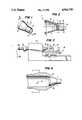
- FIG. 1is a perspective view of the lens supporting mold
- FIG. 2is an elevational cross-sectional view of the lens supporting mold taken along line 2--2 of FIG. 1 showing an optical surface formed thereon and a polymeric contact lens material cast therein in contact with the optical surface;
- FIG. 3is a side elevation view showing a lathe having a collet adapted for holding the lens supporting mold and further showing a mechanism for loading and unloading the mold;
- FIG. 4is a cross-sectional elevation view showing the lens supporting mold in intimate contact with a mating collet and showing the manner in which the mold is centered and restrained in the collet.
- the present inventionin its preferred embodiment employs a mold in which a polymeric contact lens material has been cast.
- Mold body 2 shown in FIGS. 1 and 2may be formed by injection molding, and includes a base wall 5 having an optical surface 6 formed thereon.
- optical surface 6defines a base curve corresponding to one surface of contact lens 3.
- An annular wall 14projects from the periphery of base wall 5 thereby defining pocket 15 which retains polymeric lens material 4 within mold 2 during polymerization and subsequent machining.
- a frusto-conical external surface contact section 8is shaped for colletting, centering and wedging the mold 2 within a machine such as a lathe.
- An annular supporting section 12 and an internal hollow conical cavity section 10are also formed on mold 2.
- the wall 9 of cavity 10is formed substantially parallel to surface contact section 8.
- Mold 2as injection molded, is constructed to provide precise alignment about its axis of symmetry, or centerline, 16.
- Optical surface 6is in alignment with axis 16 such that the centroid 7 of surface 6 is coincident with axis 16.
- Conical section 8is in precise alignment with optical surface 6 and axis 16 in similar fashion.
- the outer surface of mold 2can be defined as a surface of revolution about axis 16.
- Annular supporting section 12is provided at the base of conical section 8 to maintain the rigidity of the mold 2 during machining operations.
- Conical cavity section 10is dimensioned to ensure maintenance of a uniform cross-section between surface 8 and wall 9 during the injection molding of mold 2.
- Wall 9 of conical cavity section 10may serve as an internal support surface for further supporting mold 2 during subsequent machining and finishing operations, such as polishing.
- annular supporting wall 14Extending forwardly of contact section 8 and optical surface 6 is the annular supporting wall 14. This supporting wall in conjunction with optical surface 6 provides a vessel for receiving polymeric lens material 4 which is poured onto the cylindrical pocket 15 formed by surface 6 and the inner face of wall 14. Once the polymeric lens material 4 is properly polymerized and hardened, mold 2 and lens material 4 are ready for lathing.
- FIG. 3shows a preferred embodiment of a lathe for machining the molded lens material 4.
- a rotating air coupling 26is attached to a tube feeder 24 which extends into lathe spindle 20 and is fastened to a specially shaped mold collet 22.
- coupling 26is disconnected from tube feeder 24 and mold 2 is inserted into tube feeder 24 with the polymerized lens material 4 facing collet 22.
- Coupling 26is affixed to tube 24 and pneumatic pressure is applied through coupling 26 via air line 28. This provides positive pressure against mold 2 and particularly against internal wall 9 of cavity 10 thereby causing the mold 2 to propel forwardly into collet 22 to become securely and accurately wedged therein.
- the conical cavity 10facilitates the pneumatic propulsion of the mold 2 through the feed tube 24 and collet 22.
- FIG. 4demonstrates the resulting anchoring of mold 2 rigidly and accurately within its collet 22.
- Mold 2is propelled forwardly under pressure in the direction of arrow 21 and held in intimate contact against tapered internal support surface 36 provided in collet 22.
- Surface 36substantially complements the surface of external contact section 8.
- the mold 2is now suitably and automatically positioned within collet 22 to provide precise alignment, centering and accurate lens thickness control for a subsequent lens cutting operation.
- mold 2is shown securely positioned within lathe 18.
- An operatorinitially positions compound machine slide 34 at a desired cutting location on lathe 18 so that cutting tool 30 mounted on tool post 32 cuts an optical surface 19 on polymeric material 4.
- cutting tool 30has finished cutting front surface 19 on the lens material 4.
- the moldis ready for removal from lathe 18. This is accomplished by providing vacuum or suction through line 28, causing negative pressure inside the feed tube 24 and collet 22, so that mold 2 is drawn back against rotating coupling 26.
- the operatorthen disconnects coupling 26, thereby removing it from feed tube 24.
- Mold 2is held in place on coupling 26 and the lathe operator has merely to remove the mold, load another mold and repeat the lathing process. Alterations for automatically feeding and removing molds and automation of the lathe is of course possible.
- the present inventionpermits the fabrication and manufacture of contact lenses, as well as any other articles having a surface of revolution, in a precise and highly reproducible fashion. It will thus be apparent that the present invention provides a new and novel method of loading and unloading lens support molds and for manufacturing contact lenses with a high degree of accuracy.
Landscapes
- Engineering & Computer Science (AREA)
- Mechanical Engineering (AREA)
- Health & Medical Sciences (AREA)
- Manufacturing & Machinery (AREA)
- Ophthalmology & Optometry (AREA)
- Moulds For Moulding Plastics Or The Like (AREA)
- Eyeglasses (AREA)
Abstract
Description
Claims (3)
Priority Applications (1)
| Application Number | Priority Date | Filing Date | Title |
|---|---|---|---|
| US06/623,361US4924739A (en) | 1984-06-22 | 1984-06-22 | Method and apparatus for producing a contact lens |
Applications Claiming Priority (1)
| Application Number | Priority Date | Filing Date | Title |
|---|---|---|---|
| US06/623,361US4924739A (en) | 1984-06-22 | 1984-06-22 | Method and apparatus for producing a contact lens |
Publications (1)
| Publication Number | Publication Date |
|---|---|
| US4924739Atrue US4924739A (en) | 1990-05-15 |
Family
ID=24497794
Family Applications (1)
| Application Number | Title | Priority Date | Filing Date |
|---|---|---|---|
| US06/623,361Expired - LifetimeUS4924739A (en) | 1984-06-22 | 1984-06-22 | Method and apparatus for producing a contact lens |
Country Status (1)
| Country | Link |
|---|---|
| US (1) | US4924739A (en) |
Cited By (8)
| Publication number | Priority date | Publication date | Assignee | Title |
|---|---|---|---|---|
| US5071101A (en)* | 1990-03-26 | 1991-12-10 | Wood Kenneth E | Mold for an intraocular/contact lens |
| USD326102S (en) | 1989-06-15 | 1992-05-12 | Mizoguchi Iron Works & Co., Ltd. | Collet |
| US5347896A (en)* | 1992-12-21 | 1994-09-20 | Bausch & Lomb Incorporated | Automated collet loading for the manufacture of contact lenses |
| US5931068A (en)* | 1998-09-09 | 1999-08-03 | Council, Jr.; Buford W. | Method for lathing a lens |
| US20030119944A1 (en)* | 2000-12-19 | 2003-06-26 | Bausch & Lomb Incorporated | Water-soluble blocking wax formulation |
| US20100294095A1 (en)* | 2009-05-19 | 2010-11-25 | Hon Hai Precision Industry Co., Ltd. | Method for making mold core |
| US20180169980A1 (en)* | 2015-08-28 | 2018-06-21 | Coopervision International Holding Company, Lp | Method And Apparatus For Manufacturing Contact Lens Moulds |
| WO2021154692A1 (en) | 2020-01-27 | 2021-08-05 | Clearlab Sg Pte Ltd. | Actinically-crosslinkable polysiloxane-polyglycerol block copolymers and methods of making and use thereof |
Citations (8)
| Publication number | Priority date | Publication date | Assignee | Title |
|---|---|---|---|---|
| FR403402A (en)* | 1908-05-29 | 1909-11-04 | Paul Janssen | Improvements to fire extinguishers |
| US2273500A (en)* | 1939-09-18 | 1942-02-17 | Automatic Button Company | Machine for compressing lenses or the like |
| US2465677A (en)* | 1945-12-13 | 1949-03-29 | Niagara Blower Co | Holder for the ends of tubes |
| GB926072A (en)* | 1961-06-05 | 1963-05-15 | Spencer Franklin Ltd | Improvements in or relating to work-holding devices and actuating means therefor |
| US3171663A (en)* | 1960-07-15 | 1965-03-02 | James A Stark | Machine tool chucking device |
| US4103914A (en)* | 1976-08-31 | 1978-08-01 | Roehm Guenter H | Drill chuck |
| US4188353A (en)* | 1977-05-25 | 1980-02-12 | Neefe Charles W | Method of making aspheric lenses |
| US4469646A (en)* | 1982-08-09 | 1984-09-04 | Rawlings David L | Method of molding plastic contact lenses |
- 1984
- 1984-06-22USUS06/623,361patent/US4924739A/ennot_activeExpired - Lifetime
Patent Citations (8)
| Publication number | Priority date | Publication date | Assignee | Title |
|---|---|---|---|---|
| FR403402A (en)* | 1908-05-29 | 1909-11-04 | Paul Janssen | Improvements to fire extinguishers |
| US2273500A (en)* | 1939-09-18 | 1942-02-17 | Automatic Button Company | Machine for compressing lenses or the like |
| US2465677A (en)* | 1945-12-13 | 1949-03-29 | Niagara Blower Co | Holder for the ends of tubes |
| US3171663A (en)* | 1960-07-15 | 1965-03-02 | James A Stark | Machine tool chucking device |
| GB926072A (en)* | 1961-06-05 | 1963-05-15 | Spencer Franklin Ltd | Improvements in or relating to work-holding devices and actuating means therefor |
| US4103914A (en)* | 1976-08-31 | 1978-08-01 | Roehm Guenter H | Drill chuck |
| US4188353A (en)* | 1977-05-25 | 1980-02-12 | Neefe Charles W | Method of making aspheric lenses |
| US4469646A (en)* | 1982-08-09 | 1984-09-04 | Rawlings David L | Method of molding plastic contact lenses |
Cited By (19)
| Publication number | Priority date | Publication date | Assignee | Title |
|---|---|---|---|---|
| USD326102S (en) | 1989-06-15 | 1992-05-12 | Mizoguchi Iron Works & Co., Ltd. | Collet |
| US5071101A (en)* | 1990-03-26 | 1991-12-10 | Wood Kenneth E | Mold for an intraocular/contact lens |
| US5347896A (en)* | 1992-12-21 | 1994-09-20 | Bausch & Lomb Incorporated | Automated collet loading for the manufacture of contact lenses |
| US5931068A (en)* | 1998-09-09 | 1999-08-03 | Council, Jr.; Buford W. | Method for lathing a lens |
| WO2000013849A1 (en)* | 1998-09-09 | 2000-03-16 | Bausch & Lomb Incorporated | Method for lathing a lens |
| US6315650B1 (en) | 1998-09-09 | 2001-11-13 | Bausch & Lomb Incorporated | Method for lathing a lens |
| AU753974B2 (en)* | 1998-09-09 | 2002-10-31 | Bausch & Lomb Incorporated | Method for lathing a lens |
| US6786802B2 (en) | 1998-09-09 | 2004-09-07 | Bausch & Lomb Incorporated | Method for lathing a lens |
| US6586499B2 (en) | 2000-12-19 | 2003-07-01 | Bausch & Lomb Incorporated | Water-soluble blocking wax formulation |
| US20030119944A1 (en)* | 2000-12-19 | 2003-06-26 | Bausch & Lomb Incorporated | Water-soluble blocking wax formulation |
| US7101920B2 (en) | 2000-12-19 | 2006-09-05 | Bausch & Lomb Incorporated | Water-soluble blocking wax formulation |
| US20100294095A1 (en)* | 2009-05-19 | 2010-11-25 | Hon Hai Precision Industry Co., Ltd. | Method for making mold core |
| US8245608B2 (en)* | 2009-05-19 | 2012-08-21 | Hon Hai Precision Industry Co., Ltd. | Method for making mold core |
| US20180169980A1 (en)* | 2015-08-28 | 2018-06-21 | Coopervision International Holding Company, Lp | Method And Apparatus For Manufacturing Contact Lens Moulds |
| US10406768B2 (en)* | 2015-08-28 | 2019-09-10 | Coopervision International Holding Company, Lp | Method and apparatus for manufacturing contact lens moulds |
| WO2021154692A1 (en) | 2020-01-27 | 2021-08-05 | Clearlab Sg Pte Ltd. | Actinically-crosslinkable polysiloxane-polyglycerol block copolymers and methods of making and use thereof |
| US11649325B2 (en) | 2020-01-27 | 2023-05-16 | Clearlab Sg Pte Ltd. | Actinically-crosslinkable polysiloxane-polyglycerol block copolymers and methods of making and use thereof |
| US12024597B2 (en) | 2020-01-27 | 2024-07-02 | Clearlab Sg Pte Ltd. | Wound dressings comprising polysiloxane-polyglycerol block copolymers and methods of making and use thereof |
| US12037463B2 (en) | 2020-01-27 | 2024-07-16 | Clearlab Sg Pte Ltd. | Antimicrobial ophthalmic devices comprising polysiloxane-polyglycerol block copolymers and methods of making and use thereof |
Similar Documents
| Publication | Publication Date | Title |
|---|---|---|
| EP1656248B8 (en) | Method for manufacturing ophthalmic lenses using circular blanks | |
| US6786802B2 (en) | Method for lathing a lens | |
| US6383061B1 (en) | Procedure of and device for processing optical lenses | |
| US4924739A (en) | Method and apparatus for producing a contact lens | |
| US8684525B2 (en) | Method for machining an eyeglass lens blank and eyeglass lens blank comprising a connecting material and block piece | |
| US4619082A (en) | Method of manufacturing a contact lens | |
| US5972251A (en) | Method for blocking a contact lens button | |
| US3512310A (en) | Two-piece ring block for lens blanks | |
| EP0325673A2 (en) | Mold for and method of making contact and intraocular lenses | |
| CN118043170A (en) | Holder for processing optical workpieces, in particular spectacle lenses | |
| US3427703A (en) | Lens centration mounting process and apparatus | |
| US5975882A (en) | Molded optical component with gate stubs removed from peripheral rim portions | |
| US5347896A (en) | Automated collet loading for the manufacture of contact lenses | |
| KR100908291B1 (en) | Automatic supply of lens mold for contact lens cutting equipment | |
| US4844143A (en) | Mold for fixing a metal block on one of the faces of an ophthalmic lens | |
| US3815294A (en) | Method for making one-piece multifocal lenses | |
| EP0143253A1 (en) | Lens casting mold and process for using same in making an optical lens | |
| GB2216065A (en) | Contact lens production | |
| US3832920A (en) | Apparatus for and method of edging a non-rigid lens | |
| EP0732172B1 (en) | Ocular lens fabrication method and ocular lens fabrication apparatus | |
| JPH0469617A (en) | Button for contact lens and manufacture of contact lens using same | |
| JPS5979744A (en) | Bladder processing apparatus for tire vulcanization | |
| WO2001021352A1 (en) | Apparatus and method for use in manufacturing an intraocular lens | |
| HK1038206B (en) | Method for lathing a lens | |
| JPH05319840A (en) | Glass formed lens and glass lens forming die |
Legal Events
| Date | Code | Title | Description |
|---|---|---|---|
| AS | Assignment | Owner name:COOPERVISION, INC., 455 EAST MIDDLEFIELD ROAD, MOU Free format text:ASSIGNMENT OF ASSIGNORS INTEREST.;ASSIGNOR:ADEMOVIC, MARTIN K.;REEL/FRAME:004278/0014 | |
| AS | Assignment | Owner name:IRVING TRUST CO., NEW YORK BANKING CORP. Free format text:SECURITY INTEREST;ASSIGNOR:COOPER COMPANIES, INC., THE;REEL/FRAME:004932/0263 Effective date:19880815 Owner name:UNION BANK Free format text:SECURITY INTEREST;ASSIGNOR:COOPER COMPANIES, INC., THE, A DE. CORP.;REEL/FRAME:004932/0295 Effective date:19880815 Owner name:AIG CAPITAL CORP. Free format text:SECURITY INTEREST;ASSIGNOR:COOPER COMPANIES, INC.;REEL/FRAME:004932/0329 Effective date:19881229 Owner name:COOPER COMPANIES, INC., THE Free format text:CHANGE OF NAME;ASSIGNOR:COOPERVISION, INC.;REEL/FRAME:004932/0379 Effective date:19870622 Owner name:COOPER COMPANIES, INC., THE, CALIFORNIA Free format text:CHANGE OF NAME;ASSIGNOR:COOPERVISION, INC.;REEL/FRAME:004932/0379 Effective date:19870622 | |
| AS | Assignment | Owner name:COOPER COMPANIES, INC., THE, A CORP. OF DE Free format text:RELEASED BY SECURED PARTY;ASSIGNOR:AIG CAPITAL CORP.;REEL/FRAME:004985/0399 Effective date:19881108 Owner name:COOPER COMPANIES, INC., THE Free format text:RELEASED BY SECURED PARTY;ASSIGNOR:IRVING TRUST COMPANY, AS COLLATERAL AGENT;REEL/FRAME:005122/0019 Effective date:19881018 Owner name:COOPER COMPANIES, INC., THE, CALIFORNIA Free format text:RELEASED BY SECURED PARTY;ASSIGNOR:AIG CAPITAL CORP.;REEL/FRAME:004985/0399 Effective date:19881108 Owner name:COOPER COMPANIES, INC., THE, CALIFORNIA Free format text:RELEASED BY SECURED PARTY;ASSIGNOR:IRVING TRUST COMPANY, AS COLLATERAL AGENT;REEL/FRAME:005122/0019 Effective date:19881018 | |
| AS | Assignment | Owner name:DAIWA BANK, LIMITED, LOS ANGELES AGENCY, THE, A BA Free format text:SECURITY INTEREST;ASSIGNOR:COOPER COMPANIES, INC., THE;REEL/FRAME:005023/0501 Effective date:19881229 Owner name:COOPER COMPANIES, INC., THE Free format text:LICENSE;ASSIGNOR:DAIWA BANK, LIMITED, LOS ANGELES AGENCY, THE;REEL/FRAME:005023/0532 Effective date:19890115 | |
| AS | Assignment | Owner name:UNION BANK, AS COLLATERAL AGENT Free format text:SECURITY INTEREST;ASSIGNOR:COOPER COMPANIES, INC., THE;REEL/FRAME:005001/0436 Effective date:19890115 | |
| AS | Assignment | Owner name:COOPER COMPANIES, INC., THE, A CORP. OF DE Free format text:RELEASED BY SECURED PARTY;ASSIGNOR:UNION BANK;REEL/FRAME:005026/0540 Effective date:19881107 Owner name:COOPER COMPANIES, INC., THE, CALIFORNIA Free format text:RELEASED BY SECURED PARTY;ASSIGNOR:UNION BANK;REEL/FRAME:005026/0540 Effective date:19881107 | |
| FEPP | Fee payment procedure | Free format text:PAYOR NUMBER ASSIGNED (ORIGINAL EVENT CODE: ASPN); ENTITY STATUS OF PATENT OWNER: LARGE ENTITY | |
| FPAY | Fee payment | Year of fee payment:4 | |
| AS | Assignment | Owner name:COOPER COMPANIES, INC., THE, NEW JERSEY Free format text:RELEASE BY SECURED PARTY;ASSIGNOR:UNION BANK;REEL/FRAME:007197/0143 Effective date:19940923 | |
| AS | Assignment | Owner name:FOOTHILL CAPITAL CORPORATION, CALIFORNIA Free format text:SECURITY INTEREST;ASSIGNOR:COOPERVISION, INC.;REEL/FRAME:007205/0313 Effective date:19940920 | |
| AS | Assignment | Owner name:KEYBANK NATIONAL CORPORATION, NEW YORK Free format text:SECURITY AGREEMENT;ASSIGNOR:COOPERVISION, INC.;REEL/FRAME:008811/0233 Effective date:19970915 | |
| FEPP | Fee payment procedure | Free format text:PETITION RELATED TO MAINTENANCE FEES FILED (ORIGINAL EVENT CODE: PMFP); ENTITY STATUS OF PATENT OWNER: LARGE ENTITY | |
| REMI | Maintenance fee reminder mailed | ||
| FP | Lapsed due to failure to pay maintenance fee | Effective date:19980520 | |
| FPAY | Fee payment | Year of fee payment:8 | |
| SULP | Surcharge for late payment | ||
| FEPP | Fee payment procedure | Free format text:PETITION RELATED TO MAINTENANCE FEES GRANTED (ORIGINAL EVENT CODE: PMFG); ENTITY STATUS OF PATENT OWNER: LARGE ENTITY | |
| STCF | Information on status: patent grant | Free format text:PATENTED CASE | |
| PRDP | Patent reinstated due to the acceptance of a late maintenance fee | Effective date:19990430 | |
| AS | Assignment | Owner name:COOPERVISION TECHNOLOGY, INC., CALIFORNIA Free format text:ASSIGNMENT OF ASSIGNORS INTEREST;ASSIGNOR:COOPERVISION, INC.;REEL/FRAME:010371/0476 Effective date:19991026 | |
| FEPP | Fee payment procedure | Free format text:PAYOR NUMBER ASSIGNED (ORIGINAL EVENT CODE: ASPN); ENTITY STATUS OF PATENT OWNER: LARGE ENTITY | |
| FPAY | Fee payment | Year of fee payment:12 | |
| AS | Assignment | Owner name:COOPER VISION, INC., CALIFORNIA Free format text:RELEASE OF SECURITY INTEREST;ASSIGNOR:FOOTHILL CAPITAL CORPORATION;REEL/FRAME:015740/0642 Effective date:20050112 | |
| AS | Assignment | Owner name:COOPERVISION INC., CALIFORNIA Free format text:PATENT RELEASE;ASSIGNOR:KEYBANK NATIONAL ASSOCIATION;REEL/FRAME:015740/0762 Effective date:20050209 | |
| AS | Assignment | Owner name:COOPERVISION, INC., CALIFORNIA Free format text:RELEASE OF SECURITY INTEREST;ASSIGNOR:FOOTHILL CAPITAL CORPORATION;REEL/FRAME:015841/0496 Effective date:20050112 | |
| AS | Assignment | Owner name:KEYBANK NATIONAL ASSOCIATION, OHIO Free format text:SECURITY AGREEMENT;ASSIGNOR:COOPERVISION TECHNOLOGY LLC;REEL/FRAME:016016/0523 Effective date:20050106 | |
| AS | Assignment | Owner name:COOPERVISION TECHNOLOGY LLC, CALIFORNIA Free format text:RELEASE BY SECURED PARTY;ASSIGNOR:KEYBANK NATIONAL ASSOCIATION;REEL/FRAME:018837/0695 Effective date:20070131 |