US4924349A - Face plate assembly for electrical devices - Google Patents
Face plate assembly for electrical devicesDownload PDFInfo
- Publication number
- US4924349A US4924349AUS07/191,921US19192188AUS4924349AUS 4924349 AUS4924349 AUS 4924349AUS 19192188 AUS19192188 AUS 19192188AUS 4924349 AUS4924349 AUS 4924349A
- Authority
- US
- United States
- Prior art keywords
- assembly
- face member
- wallbox
- plate
- intermediate plate
- Prior art date
- Legal status (The legal status is an assumption and is not a legal conclusion. Google has not performed a legal analysis and makes no representation as to the accuracy of the status listed.)
- Expired - Lifetime
Links
- 230000002093peripheral effectEffects0.000claimsdescription14
- 230000000712assemblyEffects0.000claimsdescription4
- 238000000429assemblyMethods0.000claimsdescription4
- 238000010276constructionMethods0.000abstract1
- 239000000463materialSubstances0.000description4
- 239000002184metalSubstances0.000description3
- 230000013011matingEffects0.000description2
- 238000000034methodMethods0.000description2
- 230000000881depressing effectEffects0.000description1
- 238000009429electrical wiringMethods0.000description1
- 238000009413insulationMethods0.000description1
- 238000004519manufacturing processMethods0.000description1
- 238000000465mouldingMethods0.000description1
Images


Classifications
- H—ELECTRICITY
- H02—GENERATION; CONVERSION OR DISTRIBUTION OF ELECTRIC POWER
- H02G—INSTALLATION OF ELECTRIC CABLES OR LINES, OR OF COMBINED OPTICAL AND ELECTRIC CABLES OR LINES
- H02G3/00—Installations of electric cables or lines or protective tubing therefor in or on buildings, equivalent structures or vehicles
- H02G3/02—Details
- H02G3/08—Distribution boxes; Connection or junction boxes
- H02G3/14—Fastening of cover or lid to box
Definitions
- This inventionrelates to a wallbox-mountable face plate assembly and, more particularly, to an assembly that includes a three-piece mounting arrangement.
- Wallbox-mountable electrical controlsare well known and in widespread use. In many cases, these controls are simple toggle switches to turn on and off lights, or other electrically-powered devices, or both. In other cases, the control in the wallbox is a dimmer, which can continuously vary power to a load, typically a lighting load or a motor.
- a variety of face plate assemblieshave been designed to cover the wall box and wiring, while still permitting access to the electrical control.
- a plate with a rectangular slotis a simple configuration often used with a toggle switch. More complex configurations have been designed to serve various functional or aesthetic considerations.
- a touch switch assemblythat likewise has a face plate whose mounting means are not visible from the front of the plate was disclosed in U.S. Pat. No. 4,563,592, issued Jan. 7, 1986 to S. J. Yuhasz et al.
- a push-button light switch sold under the "Jung” name, in Germany,comprises a mounting plate assembly that includes flexible snaps to connect with mating members on a cover plate/push-button.
- linear slide dimmer assemblyis the NOVA® dimmer, sold by Lutron Electronics Co. That assembly includes a metal yoke that mounts to a wallbox, a slide that moves between rails on the yoke, and a faceplate that has, on its back surface (facing the wallbox), snaps that connect to the rails.
- a wallbox-mountable face plate assemblycomprises, in combination,
- a generally flat intermediate plateremovably attachable to said support plate, having a first surface that is adjacent to a surface of said support plate when said plates are attached and, opposite said first surface, a second surface that faces outward when said plates are mounted in a wallbox, said second surface being interrupted by a peripheral, outward-facing first cantilever snap;
- the assemblypermits a face plate member to be mounted without tools and without any outward signs of the mounting mechanism, while permitting this member to have a simple structure, easily-fabricated from a wise variety of materials.
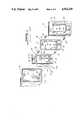
- FIG. 1is an exploded view of a prior art wallbox, light dimmer, and face plate.
- FIG. 2is an exploded view of an embodiment of the present invention.
- FIG. 3is a cross section taken along line 3--3 of FIG. 2.
- FIG. 4is a cross section taken along line 4--4 of FIG. 2.
- FIG. 5A and 5Bare elevational views of other embodiments of the present invention.
- FIG. 6is an elevational view of the front surface of an alternative embodiment of this invention.
- FIG. 7is a cross section taken along the line 7--7 in FIG. 6.
- the present inventionprovides an assembly that permits snap-mounting of a simplified face plate onto a wallbox-mounted wiring device.
- top and bottomand “front” and “rear” with reference to the assembly when it is mounted in the wallbox.
- a rear surfaceis, then, a surface that faces inward toward the wallbox; a front surface faces outward.
- Longitudinalrefers to up and down, “lateral” to left and right.
- FIG. 1shows a conventional metal wallbox 30, which is adapted to be mounted within the wall of a building.
- the wallboxwhose opening is generally flush with the surface of the wall, provides a metallic enclosure to receive a wiring device.
- Other wallboxescan be used in connection with the invention, including wallboxes having insulation body portions.
- Wiring devicewhen use in the present specification and claims, is to be interpreted broadly, to include receptacles, jacks, displays, outlets, switches, dimmers, and other devices that may be mounted in wallboxes.
- Wallbox 30has "knock-outs" to permit the introduction of electrical wiring, which extends through the building walls, shown as wires 30a and 30b in FIG. 1. Wires 30a and 30b are part of the building wiring and can be connected to lamp loads or the like which are to be controlled by the electrical control device. Wallbox 30 is also provided with threaded mounting openings 31 and 32, which are on standard centers and are adapted to receive mounting screws for mounting a control device within wallbox 30.
- Wiring device 40 of FIG. 1is a light dimmer.
- Light dimmer 40consists of a metallic yoke plate 41 having a backbox 42 on its rear surface and a rectangular escutcheon 43 extending from its front surface.
- a manually operable sliderhas a slider handle 43a projecting beyond the front surface of escutcheon 43. Movement of the handle between its end positions causes dimming of the lighting load and, when the lowest position is reached, causes the opening of a switch that is in series with wires 44 and 45 to turn off the lighting load.
- Backbox 42encloses the control mechanism of dimmer 40 and insulates it from accidental contact with wires or grounds in wallbox 30.
- Leads 44 and 45extend through an opening in backbox 42 and may be connected to wires 30a and 30b.
- Yoke plate 41which preferably is a generally flat thin metal stamping, is of conventional structure and has two laterally elongated openings 46 and 47 for receiving mounting screws 48 and 49. Screws 48 and 49 pass through openings 46 and 47, respectively, and are threaded into openings 31 and 32, respectively, to mount dimmer 40 to wallbox 30. Yoke 41 also has tapped openings 50 and 51, which are on standard centers and receive screws 52 and 53.
- Adapter plate 70is a generally flat plate having laterally elongated openings 72 and 73 which are sufficiently large to receive the protruding heads of screws 48 and 49 after those screws are screwed into place in wallbox 30. Screws 52 and 53 thread into openings 50 and 51, respectively, in order to hold adapter plate 70 to yoke 41. Openings 74 and 75 receive screws 52 and 53, and opening 76 receives escutcheon 43.
- Wall plate 71has a rectangular opening 90, which fits over escutcheon 43, and connectors 92, 93, 94, and 95, which are elongated pedestals adapted to penetrate and then snap behind openings 80 to 83, respectively, in adapter plate 70.
- the assembly of the present inventionincludes, beginning at the rear, a wiring device that fits on or within a wallbox, a support plate for the device, an intermediate plate that mounts against the front surface of the support plate, and a face member that mounts against the front surface of the intermediate plate.
- the intermediate platepreferably has a generally rectangular shape.
- the wiring devicecan take a variety of forms, including an on-off switch, a dimmer, or a combination dimmer and switch.
- dimmerwe mean a device that controls the power to a load, which could be a lighting load, a motor, or other electrical load.
- FIG. 2depicts an embodiment of the present invention, together with a wallbox into which it mounts.
- Wallbox 33can be of the same type as is shown in FIG. 1, which is a style of wallbox commonly used in the U.S. However, in FIG. 2, wallbox 33 is of a type more commonly used in the United Kingdom and other Western European countries. Thus, wallbox 33 has a square front opening and laterally spaced tapped holes 34 and 35.
- Wiring device 98is mounted on the rear surface of support plate 100.
- wiring device 98is a linear slide dimmer, including a slide potentiometer whose shaft 102 protrudes from slot 104 in plate 100.
- screws 106 and 108pass through holes 110 and 112 and screw into tapped holes 34 and 35, respectively.
- Tapped holes 114, 116, 118, and 120receive screws for mounting the intermediate plate, and hole 124 receives an optional capture screw, as described below.
- Support plate 100may be of any rigid material, metallic or non-metallic.
- Slot 104may be longitudinal (as shown) or lateral.
- Intermediate plate 130is attached to support plate 100 by four screws. For clarity, screw 132 is shown, but the corresponding screws 134, 136, and 138 are not. The screws pass through holes 140, 142, 144, and 146 into holes 114, 116, 118, and 120, respectively. Openings 147 and 148 receive the heads of screws 106 and 108. Slot 149 permits shaft 102 to pass to slider 150, which captures the shaft and moves it up and down as it slides in a channel bounded by guide edges 152 and 154 and stop edges 156 and 158. Capturing the slider so that it cannot be removed without a tool is an advantage from a safety standpoint. As shown in FIG. 2, slider 150 is optionally captured by tab 160 and capture screw 162.
- FIG. 3is a cross section taken along line 3--3.
- lip 163determines the position of the head of screw 162 for capturing slider 150.
- Cantilever snaps 164, 166, 168, and 170may be formed, among other ways, by cutting away surrounding material of intermediate plate 130 or by molding.
- Face plate 180with length and width dimensions slightly greater than those of intermediate plate 130, covers the latter, except for opening 182, which provides access to slider 150 along its range of travel.
- An integral, inward-extending flange 184defines the perimeter of face plate 180 and covers at least a part of the perimeter of intermediate plate 130.
- the interior face of flange 184has protrusions 186, 188, 190, and 192, of a generally triangular cross section, to connect to cantilever snaps 164, 166, 168, and 170, respectively.
- the front surfaceneed have no features that relate to mounting. This permits the face plate to have a particularly simple and sturdy structure, readily fabricated from a variety of materials.
- FIG. 4is a cross section along line 4-4 through cantilever snap 164 on intermediate plate 130 and connector protrusion 186 on flange 184 of face plate 180.
- a single cantilever snap-connector pairmay be used.
- cantilever snapsare at two opposite ends of intermediate plate 130, with corresponding connectors on flange 184. More preferably, as shown in FIG. 2, there are four snaps like 164 and four mating connectors like 186.
- a snapcould extend along an entire edge of plate 130, a protrusion could extend along an entire face of flange 184, or both. If a protrusion extends along an entire face, the corresponding edge of plate 130 could be cut away slightly, if necessary, to accept it.
- cantilever snaps 164 and 166, 168 and 170are at the top and bottom edges respectively of intermediate plate 130.
- the snapscould be on the left and right edges instead (or in addition). Having the snaps at the top and bottom edges facilitates lateral "ganging"; that is, having more than one device mounted side-by side. In that case, a single "multi-gang" face plate can cover the devices. For the same reason, snaps at the left and right edges are preferred for longitudinal ganging, which is less common, however.
- FIG. 5Adepicts a multi-gang face plate covering two side-by-side mounted dimmers.
- FIG. 5Bdepicts a multi-gang face plate covering two dimmers mounted one below the other.
- Wiring device 98may be a switch, rather than a dimmer.
- Face plate member 180may have an opening (like 182) to provide access to the switch. Alternatively, it may have no opening in order to impede, and to limit, access to the switch.
- FIG. 6depicts an embodiment in which the wiring device is a push-button switch actuated through an opening in the face plate by a touch plate 200.
- FIG. 7depicts a cross section taken along line 7--7 of FIG. 6. Depressing touch plate 200 causes plunger 202 to open and close the switch contacts in element 204. Plunger 202 passes through clearance hole 208 in support plate 100.
- intermediate plate 130is visible behind face plate 180 when the assembly is viewed at a large angle to a normal to the touch plate.
- intermediate plate 130can be painted to match--or to contrast with--the color of the wall 210 on which the assembly is mounted.
- intermediate plate 130could be translucent; that is, it transmits at least a substantial fraction of light incident upon it.
- the intermediate platecould be backlighted by lamp 212 through opening 214 in support plate 100 to provide an attractive appearance, with an opaque or translucent face member.
- the lightcan function as a night light or pilot light.
Landscapes
- Engineering & Computer Science (AREA)
- Architecture (AREA)
- Civil Engineering (AREA)
- Structural Engineering (AREA)
- Switch Cases, Indication, And Locking (AREA)
- Casings For Electric Apparatus (AREA)
- Illuminated Signs And Luminous Advertising (AREA)
Abstract
Description
Claims (18)
Priority Applications (3)
| Application Number | Priority Date | Filing Date | Title |
|---|---|---|---|
| US07/191,921US4924349A (en) | 1988-05-09 | 1988-05-09 | Face plate assembly for electrical devices |
| DE68914877TDE68914877T2 (en) | 1988-05-09 | 1989-02-21 | Assembly with cover plate for electrical devices. |
| EP89301646AEP0341805B1 (en) | 1988-05-09 | 1989-02-21 | Face plate assembly for electrical devices |
Applications Claiming Priority (1)
| Application Number | Priority Date | Filing Date | Title |
|---|---|---|---|
| US07/191,921US4924349A (en) | 1988-05-09 | 1988-05-09 | Face plate assembly for electrical devices |
Publications (1)
| Publication Number | Publication Date |
|---|---|
| US4924349Atrue US4924349A (en) | 1990-05-08 |
Family
ID=22707461
Family Applications (1)
| Application Number | Title | Priority Date | Filing Date |
|---|---|---|---|
| US07/191,921Expired - LifetimeUS4924349A (en) | 1988-05-09 | 1988-05-09 | Face plate assembly for electrical devices |
Country Status (3)
| Country | Link |
|---|---|
| US (1) | US4924349A (en) |
| EP (1) | EP0341805B1 (en) |
| DE (1) | DE68914877T2 (en) |
Cited By (70)
| Publication number | Priority date | Publication date | Assignee | Title |
|---|---|---|---|---|
| US5191971A (en)* | 1991-04-05 | 1993-03-09 | Lutron Electronics Co., Inc. | Multi-position wall mountable control switch with tactile feedback linear actuator |
| USD380453S (en)* | 1996-01-23 | 1997-07-01 | Leviton Manufacturing Co., Inc. | Faceplate for a rotary switch housing |
| US5660459A (en)* | 1996-04-19 | 1997-08-26 | E-Lite Technologies, Inc. | Illuminated assembly for a switch/outlet |
| CN1047884C (en)* | 1994-10-25 | 1999-12-29 | 布蒂克诺公司 | Modular structure for wall-mounting of electrical equipment |
| US6135618A (en)* | 1998-11-17 | 2000-10-24 | Tai; Jen-Lung David | Electrical fixture and method of installing an electrical fixture |
| US6565236B1 (en) | 2001-09-21 | 2003-05-20 | Frank H. Davis, Jr. | Through wall light fixture |
| US6774328B2 (en)* | 2002-05-10 | 2004-08-10 | Lutron Electronics Co., Inc. | Dimmer having a thermally insulated faceplate fastener |
| US20050194176A1 (en)* | 2004-02-25 | 2005-09-08 | Control4 Corporation | Faceplate attachment system |
| US20050200284A1 (en)* | 2004-03-09 | 2005-09-15 | Edgecom | An apparatus that enables low cost installation of a secure and tamper proof assembly that accommodates lifeline support for power line communication devices. |
| USD513607S1 (en)* | 2004-12-16 | 2006-01-17 | Leviton Manufacturing Co, Inc. | Combined rocker on-off switch and rocker dimmer switch |
| US20060018339A1 (en)* | 1998-07-28 | 2006-01-26 | Serconet, Ltd | Local area network of serial intelligent cells |
| USD521944S1 (en)* | 2004-12-20 | 2006-05-30 | Leviton Manufacturing Co., Inc. | Combined tactile on-off switch and slide dimmer switch |
| USD522465S1 (en)* | 2004-12-16 | 2006-06-06 | Leviton Manufacturing Co., Inc. | Combined tactile on-off switch and tactile dimmer switch |
| USD523402S1 (en)* | 2004-12-20 | 2006-06-20 | Leviton Manufacturing Co., Inc. | Combined tactile on-off switch and thumbwheel dimmer switch |
| USD523824S1 (en)* | 2004-12-16 | 2006-06-27 | Leviton Manufacturing Co., Inc. | Combined rocker on-off switch and tactile dimmer switch |
| US20060182094A1 (en)* | 2000-04-18 | 2006-08-17 | Serconet Ltd. | Telephone communication system over a single telephone line |
| US20060197428A1 (en)* | 2005-02-21 | 2006-09-07 | Takeshi Tonegawa | Electron devices with non-evaporation-type getters and method for manufacturing the same |
| US20060255662A1 (en)* | 2005-05-12 | 2006-11-16 | Lutron Electronics Co., Inc. | Lighting control having a captured offset linear guide system |
| US20070019669A1 (en)* | 2003-07-09 | 2007-01-25 | Serconet Ltd. | Modular outlet |
| US20070047573A1 (en)* | 2005-08-29 | 2007-03-01 | Arkados, Inc. | Networking and multimedia adapter for power outlets |
| USD539759S1 (en)* | 2004-12-20 | 2007-04-03 | Leviton Manufacturing Co., Inc. | Combined tactile on-off switch and rocker dimmer switch |
| US20070272535A1 (en)* | 2006-05-24 | 2007-11-29 | Greg Edward Sloan | Wallbox dimmer having a sliding cover plate |
| US20080103706A1 (en)* | 2006-10-27 | 2008-05-01 | Hon Hai Precision Industry Co., Ltd. | System and method for testing leds on a motherboard |
| US7399205B2 (en) | 2003-08-21 | 2008-07-15 | Hill-Rom Services, Inc. | Plug and receptacle having wired and wireless coupling |
| US7416310B1 (en)* | 2003-12-02 | 2008-08-26 | Pass & Seymour, Inc. | Power control device for an electrical load |
| US20080227333A1 (en)* | 2004-02-16 | 2008-09-18 | Serconet Ltd. | Outlet add-on module |
| US7453895B2 (en) | 2001-10-11 | 2008-11-18 | Serconet Ltd | Outlet with analog signal adapter, a method for use thereof and a network using said outlet |
| US7483524B2 (en) | 1999-07-20 | 2009-01-27 | Serconet, Ltd | Network for telephony and data communication |
| US7497582B1 (en)* | 2003-12-02 | 2009-03-03 | Pass & Seymour, Inc. | Power control device and heat sink |
| US7522615B2 (en) | 2002-11-13 | 2009-04-21 | Serconet, Ltd. | Addressable outlet, and a network using same |
| USD597496S1 (en)* | 2008-08-29 | 2009-08-04 | Lutron Electronics Co., Inc. | Dimmer switch |
| USD597495S1 (en)* | 2008-08-29 | 2009-08-04 | Lutron Electronics Co., Inc. | Dimmer switch |
| USD600656S1 (en)* | 2008-01-09 | 2009-09-22 | Lutron Electronics Co., Inc. | Dimmer switch |
| US20090298406A1 (en)* | 2008-06-03 | 2009-12-03 | Norbury Jr Raymond L | Illuminated vent housing |
| USD606028S1 (en) | 2008-11-04 | 2009-12-15 | Leviton Manufacturing Co., Inc. | Dimmer switch |
| USD606029S1 (en) | 2008-11-04 | 2009-12-15 | Leviton Manufacturing Co., Inc. | Dimmer switch |
| US7680255B2 (en) | 2001-07-05 | 2010-03-16 | Mosaid Technologies Incorporated | Telephone outlet with packet telephony adaptor, and a network using same |
| USD616838S1 (en) | 2008-12-19 | 2010-06-01 | Lutron Electronics Co., Inc. | Dimmer switch |
| USD616837S1 (en) | 2008-12-19 | 2010-06-01 | Lutron Electronics Co., Inc. | Dimmer switch |
| US7821160B1 (en) | 2010-01-05 | 2010-10-26 | Inncom International Inc. | Modular wall box system |
| US7873058B2 (en) | 2004-11-08 | 2011-01-18 | Mosaid Technologies Incorporated | Outlet with analog signal adapter, a method for use thereof and a network using said outlet |
| US20110140548A1 (en)* | 2009-12-08 | 2011-06-16 | Lutron Electronics Co., Inc. | Method and Apparatus for Converting an Electronic Switch to a Dimmer Switch |
| US20110222195A1 (en)* | 2003-10-07 | 2011-09-15 | Pass & Seymour, Inc. | Plug tail systems |
| US8258973B2 (en) | 2005-02-11 | 2012-09-04 | Hill-Rom Services, Inc. | Transferable patient care equipment support |
| US20130152358A1 (en)* | 2011-12-16 | 2013-06-20 | Chrysler Group Llc | Guidance tool for adjusting position of autonomous cruise control assembly |
| US20130277086A1 (en)* | 2012-04-19 | 2013-10-24 | Pass & Seymour, Inc. | Modular electrical wiring device system |
| US8582598B2 (en) | 1999-07-07 | 2013-11-12 | Mosaid Technologies Incorporated | Local area network for distributing data communication, sensing and control signals |
| US20140090509A1 (en)* | 2011-05-18 | 2014-04-03 | Legrand Snc | Mechanical assembly of the press-button type, and application to an electrical apparatus |
| US8853893B2 (en) | 2011-11-02 | 2014-10-07 | Pass & Seymour, Inc. | Electrical wiring device for lighting control |
| USD729612S1 (en) | 2013-09-18 | 2015-05-19 | Electronic Theatre Controls, Inc. | Wallstation faceplate |
| US9281139B2 (en) | 2014-01-13 | 2016-03-08 | Electronic Theatre Controls, Inc. | Cover assembly for an electrical switch |
| US9287690B2 (en) | 2013-03-14 | 2016-03-15 | Lutron Electronics Co., Inc. | Glass faceplate for keypad of a load control system |
| US9559505B2 (en) | 2014-07-11 | 2017-01-31 | Lutron Electronics Co., Inc. | Multi-gang faceplate assembly for load control devices |
| US9574788B2 (en) | 2011-06-02 | 2017-02-21 | Cary Products Co., Inc. | Headliner vent housing |
| USD787453S1 (en)* | 2016-03-09 | 2017-05-23 | Lutron Electronics Co., Inc. | Dimmer switch |
| USD787454S1 (en)* | 2016-03-09 | 2017-05-23 | Lutron Electronics Co., Inc. | Dimmer switch |
| USD788050S1 (en)* | 2016-03-09 | 2017-05-30 | Lutron Electronics Co., Inc. | Dimmer switch |
| USD797062S1 (en)* | 2016-03-09 | 2017-09-12 | Lutron Electronics Co., Inc. | Dimmer switch |
| USD808344S1 (en)* | 2016-03-09 | 2018-01-23 | Lutron Electronics Co., Inc. | Dimmer switch |
| USD836048S1 (en) | 2016-10-26 | 2018-12-18 | Cary Products Co., Inc. | Three vane louver |
| US10181385B2 (en) | 2015-04-20 | 2019-01-15 | Lutron Electronics Co., Inc. | Control devices having independently suspended buttons for controlled actuation |
| US20190132935A1 (en)* | 2017-11-01 | 2019-05-02 | Lite-On Electronics (Guangzhou) Limited | Switch apparatus |
| US10395769B2 (en) | 2015-12-16 | 2019-08-27 | Hill-Rom Services, Inc. | Patient care devices with local indication of correspondence and power line interconnectivity |
| US10986165B2 (en) | 2004-01-13 | 2021-04-20 | May Patents Ltd. | Information device |
| USD937790S1 (en)* | 2018-11-16 | 2021-12-07 | Promier Products Inc. | Light switch with sliding actuator and integrated light source |
| USD957912S1 (en)* | 2020-11-25 | 2022-07-19 | Enerlites Inc. | Combined push-on wall plate and cover |
| USD957913S1 (en)* | 2021-01-17 | 2022-07-19 | Delta Faucet Company | Cover plate |
| US12186241B2 (en) | 2021-01-22 | 2025-01-07 | Hill-Rom Services, Inc. | Time-based wireless pairing between a medical device and a wall unit |
| US12279999B2 (en) | 2021-01-22 | 2025-04-22 | Hill-Rom Services, Inc. | Wireless configuration and authorization of a wall unit that pairs with a medical device |
| US12442832B2 (en) | 2022-12-21 | 2025-10-14 | Abl Ip Holding Llc | Wall-mounted controller with anti-tamper feature |
Families Citing this family (9)
| Publication number | Priority date | Publication date | Assignee | Title |
|---|---|---|---|---|
| ES2144956B1 (en)* | 1998-05-22 | 2001-01-01 | Schneider Electric Espana Sa | MODULAR ASSEMBLY FOR ELECTRICAL MECHANISMS. |
| FR2796802B1 (en)* | 1999-07-22 | 2001-10-26 | Legrand Sa | HOUSING, ESPECIALLY FOR ELECTRICAL EQUIPMENT |
| DE19952600A1 (en)* | 1999-11-02 | 2001-05-03 | Berker Geb | Cover frame for electrical installation devices |
| US6680438B1 (en) | 2003-01-16 | 2004-01-20 | Robert W. Campbell | Decorative electrical outlet and switch plate cover |
| DE102004005984A1 (en)* | 2004-02-06 | 2005-09-01 | Siemens Ag | Cover frame as well as control panel and functional part for an electrical installation device |
| DE202004005074U1 (en)* | 2004-03-29 | 2005-08-11 | Gira Giersiepen Gmbh & Co. Kg | Holder for insert of electric installation appliance, e.g. switch, plug socket, bus gear, etc. on support plate within support plate aperture, with support part for indirect insert fastening, with support part located in same plane |
| US20080236860A1 (en)* | 2007-04-02 | 2008-10-02 | Prevention Products, Inc. | Electrical switch cover |
| FR2935191B1 (en)* | 2008-08-20 | 2010-08-13 | Legrand France | ELECTRICAL EQUIPMENT COMPRISING LIGHTING MEANS ON BOARD OF THE APPARATUS |
| GB2507078A (en)* | 2012-10-18 | 2014-04-23 | Martin Kelly | Electrical fitting with removable faceplate |
Citations (10)
| Publication number | Priority date | Publication date | Assignee | Title |
|---|---|---|---|---|
| US2740873A (en)* | 1952-07-17 | 1956-04-03 | Touch Plate Mfg Corp | Household switch mechanism |
| US3197549A (en)* | 1962-06-22 | 1965-07-27 | Raymond J Good | Cover assembly for an outlet box and supporting wall mat therefor |
| US3639745A (en)* | 1969-06-13 | 1972-02-01 | Omron Tateisi Electronics Co | Mounting arrangement for electrical device |
| US3735020A (en)* | 1971-09-29 | 1973-05-22 | Lutron Electronics Co | Heat sink wall plate with off-center mounting openings |
| US4255780A (en)* | 1979-06-14 | 1981-03-10 | Sakellaris Peter C | Illumination assembly for use with electrical terminal units |
| US4255637A (en)* | 1978-05-26 | 1981-03-10 | Toyostar Corporation | Light regulator switch |
| US4340795A (en)* | 1980-07-29 | 1982-07-20 | Amf Incorporated | Panel mount adapter for switches |
| US4455546A (en)* | 1983-02-28 | 1984-06-19 | Prescolite, A Div. Of U.S. Indus. | Variable resistor and switch assembly having separate sliders |
| US4500746A (en)* | 1980-03-14 | 1985-02-19 | Slater Electric Inc. | Self-contained electrical wiring device |
| US4563592A (en)* | 1983-10-13 | 1986-01-07 | Lutron Electronics Co. Inc. | Wall box dimmer switch with plural remote control switches |
Family Cites Families (3)
| Publication number | Priority date | Publication date | Assignee | Title |
|---|---|---|---|---|
| FR1476721A (en)* | 1966-02-23 | 1967-04-14 | Bassani Spa | Electrical equipment for button and light plate to be recessed into a wall |
| DE6751595U (en)* | 1968-08-01 | 1969-01-30 | Siemens Ag | RECTANGULAR HOUSING MADE OF THERMOPLASTIC FOR WATER-PROTECTED INSTALLATION EQUIPMENT |
| US3864561A (en)* | 1973-03-19 | 1975-02-04 | Lutron Electronics Co | Dimmer switch with illuminated knob |
- 1988
- 1988-05-09USUS07/191,921patent/US4924349A/ennot_activeExpired - Lifetime
- 1989
- 1989-02-21EPEP89301646Apatent/EP0341805B1/ennot_activeExpired - Lifetime
- 1989-02-21DEDE68914877Tpatent/DE68914877T2/ennot_activeExpired - Lifetime
Patent Citations (10)
| Publication number | Priority date | Publication date | Assignee | Title |
|---|---|---|---|---|
| US2740873A (en)* | 1952-07-17 | 1956-04-03 | Touch Plate Mfg Corp | Household switch mechanism |
| US3197549A (en)* | 1962-06-22 | 1965-07-27 | Raymond J Good | Cover assembly for an outlet box and supporting wall mat therefor |
| US3639745A (en)* | 1969-06-13 | 1972-02-01 | Omron Tateisi Electronics Co | Mounting arrangement for electrical device |
| US3735020A (en)* | 1971-09-29 | 1973-05-22 | Lutron Electronics Co | Heat sink wall plate with off-center mounting openings |
| US4255637A (en)* | 1978-05-26 | 1981-03-10 | Toyostar Corporation | Light regulator switch |
| US4255780A (en)* | 1979-06-14 | 1981-03-10 | Sakellaris Peter C | Illumination assembly for use with electrical terminal units |
| US4500746A (en)* | 1980-03-14 | 1985-02-19 | Slater Electric Inc. | Self-contained electrical wiring device |
| US4340795A (en)* | 1980-07-29 | 1982-07-20 | Amf Incorporated | Panel mount adapter for switches |
| US4455546A (en)* | 1983-02-28 | 1984-06-19 | Prescolite, A Div. Of U.S. Indus. | Variable resistor and switch assembly having separate sliders |
| US4563592A (en)* | 1983-10-13 | 1986-01-07 | Lutron Electronics Co. Inc. | Wall box dimmer switch with plural remote control switches |
Non-Patent Citations (5)
| Title |
|---|
| Albrecht Jung Elektrotechnische Fabrik, Katalog 85, pp. 11, 14.* |
| Lutron Electronics Co. Nova Brochure P/N 362 023.* |
| Lutron Electronics Co.-Nova® Brochure P/N 362-023. |
| Robertshaw Controls Company Installation Instructions for Heating Thermostat Model T10 1141.* |
| Robertshaw Controls Company-Installation Instructions for Heating Thermostat Model T10-1141. |
Cited By (145)
| Publication number | Priority date | Publication date | Assignee | Title |
|---|---|---|---|---|
| US5191971A (en)* | 1991-04-05 | 1993-03-09 | Lutron Electronics Co., Inc. | Multi-position wall mountable control switch with tactile feedback linear actuator |
| CN1047884C (en)* | 1994-10-25 | 1999-12-29 | 布蒂克诺公司 | Modular structure for wall-mounting of electrical equipment |
| USD380453S (en)* | 1996-01-23 | 1997-07-01 | Leviton Manufacturing Co., Inc. | Faceplate for a rotary switch housing |
| US5660459A (en)* | 1996-04-19 | 1997-08-26 | E-Lite Technologies, Inc. | Illuminated assembly for a switch/outlet |
| US7221679B2 (en) | 1998-07-28 | 2007-05-22 | Serconet Ltd. | Local area network of serial intelligent cells |
| US8885659B2 (en) | 1998-07-28 | 2014-11-11 | Conversant Intellectual Property Management Incorporated | Local area network of serial intelligent cells |
| US7187695B2 (en) | 1998-07-28 | 2007-03-06 | Serconet Ltd. | Local area network of serial intelligent cells |
| US7986708B2 (en) | 1998-07-28 | 2011-07-26 | Mosaid Technologies Incorporated | Local area network of serial intelligent cells |
| US20060018339A1 (en)* | 1998-07-28 | 2006-01-26 | Serconet, Ltd | Local area network of serial intelligent cells |
| US7965735B2 (en) | 1998-07-28 | 2011-06-21 | Mosaid Technologies Incorporated | Local area network of serial intelligent cells |
| US8867523B2 (en) | 1998-07-28 | 2014-10-21 | Conversant Intellectual Property Management Incorporated | Local area network of serial intelligent cells |
| US8885660B2 (en) | 1998-07-28 | 2014-11-11 | Conversant Intellectual Property Management Incorporated | Local area network of serial intelligent cells |
| US8908673B2 (en) | 1998-07-28 | 2014-12-09 | Conversant Intellectual Property Management Incorporated | Local area network of serial intelligent cells |
| US6135618A (en)* | 1998-11-17 | 2000-10-24 | Tai; Jen-Lung David | Electrical fixture and method of installing an electrical fixture |
| US8582598B2 (en) | 1999-07-07 | 2013-11-12 | Mosaid Technologies Incorporated | Local area network for distributing data communication, sensing and control signals |
| US8351582B2 (en) | 1999-07-20 | 2013-01-08 | Mosaid Technologies Incorporated | Network for telephony and data communication |
| US8929523B2 (en) | 1999-07-20 | 2015-01-06 | Conversant Intellectual Property Management Inc. | Network for telephony and data communication |
| US7483524B2 (en) | 1999-07-20 | 2009-01-27 | Serconet, Ltd | Network for telephony and data communication |
| US7492875B2 (en) | 1999-07-20 | 2009-02-17 | Serconet, Ltd. | Network for telephony and data communication |
| US20060182094A1 (en)* | 2000-04-18 | 2006-08-17 | Serconet Ltd. | Telephone communication system over a single telephone line |
| US8559422B2 (en) | 2000-04-18 | 2013-10-15 | Mosaid Technologies Incorporated | Telephone communication system over a single telephone line |
| US7466722B2 (en) | 2000-04-18 | 2008-12-16 | Serconet Ltd | Telephone communication system over a single telephone line |
| US7593394B2 (en) | 2000-04-18 | 2009-09-22 | Mosaid Technologies Incorporated | Telephone communication system over a single telephone line |
| US7197028B2 (en) | 2000-04-18 | 2007-03-27 | Serconet Ltd. | Telephone communication system over a single telephone line |
| US7397791B2 (en) | 2000-04-18 | 2008-07-08 | Serconet, Ltd. | Telephone communication system over a single telephone line |
| US8000349B2 (en) | 2000-04-18 | 2011-08-16 | Mosaid Technologies Incorporated | Telephone communication system over a single telephone line |
| US8223800B2 (en) | 2000-04-18 | 2012-07-17 | Mosaid Technologies Incorporated | Telephone communication system over a single telephone line |
| US7680255B2 (en) | 2001-07-05 | 2010-03-16 | Mosaid Technologies Incorporated | Telephone outlet with packet telephony adaptor, and a network using same |
| US6565236B1 (en) | 2001-09-21 | 2003-05-20 | Frank H. Davis, Jr. | Through wall light fixture |
| US7889720B2 (en) | 2001-10-11 | 2011-02-15 | Mosaid Technologies Incorporated | Outlet with analog signal adapter, a method for use thereof and a network using said outlet |
| US7953071B2 (en) | 2001-10-11 | 2011-05-31 | Mosaid Technologies Incorporated | Outlet with analog signal adapter, a method for use thereof and a network using said outlet |
| US7453895B2 (en) | 2001-10-11 | 2008-11-18 | Serconet Ltd | Outlet with analog signal adapter, a method for use thereof and a network using said outlet |
| US7860084B2 (en) | 2001-10-11 | 2010-12-28 | Mosaid Technologies Incorporated | Outlet with analog signal adapter, a method for use thereof and a network using said outlet |
| US6774328B2 (en)* | 2002-05-10 | 2004-08-10 | Lutron Electronics Co., Inc. | Dimmer having a thermally insulated faceplate fastener |
| US7911992B2 (en) | 2002-11-13 | 2011-03-22 | Mosaid Technologies Incorporated | Addressable outlet, and a network using the same |
| US8295185B2 (en) | 2002-11-13 | 2012-10-23 | Mosaid Technologies Inc. | Addressable outlet for use in wired local area network |
| US7522615B2 (en) | 2002-11-13 | 2009-04-21 | Serconet, Ltd. | Addressable outlet, and a network using same |
| US7990908B2 (en) | 2002-11-13 | 2011-08-02 | Mosaid Technologies Incorporated | Addressable outlet, and a network using the same |
| US20070019669A1 (en)* | 2003-07-09 | 2007-01-25 | Serconet Ltd. | Modular outlet |
| US7688841B2 (en) | 2003-07-09 | 2010-03-30 | Mosaid Technologies Incorporated | Modular outlet |
| US7873062B2 (en) | 2003-07-09 | 2011-01-18 | Mosaid Technologies Incorporated | Modular outlet |
| US7867035B2 (en) | 2003-07-09 | 2011-01-11 | Mosaid Technologies Incorporated | Modular outlet |
| US7399205B2 (en) | 2003-08-21 | 2008-07-15 | Hill-Rom Services, Inc. | Plug and receptacle having wired and wireless coupling |
| US9142923B2 (en) | 2003-08-21 | 2015-09-22 | Hill-Rom Services, Inc. | Hospital bed having wireless data and locating capability |
| US10206837B2 (en) | 2003-08-21 | 2019-02-19 | Hill-Rom Services, Inc. | Hospital bed and room communication modules |
| US20110210833A1 (en)* | 2003-08-21 | 2011-09-01 | Mcneely Craig A | Combined power and data cord and receptacle |
| US9925104B2 (en) | 2003-08-21 | 2018-03-27 | Hill-Rom Services, Inc. | Hospital bed and room communication modules |
| US9572737B2 (en) | 2003-08-21 | 2017-02-21 | Hill-Rom Services, Inc. | Hospital bed having communication modules |
| US8727804B2 (en) | 2003-08-21 | 2014-05-20 | Hill-Rom Services, Inc. | Combined power and data cord and receptacle |
| US8092258B2 (en) | 2003-09-07 | 2012-01-10 | Mosaid Technologies Incorporated | Modular outlet |
| US8235755B2 (en) | 2003-09-07 | 2012-08-07 | Mosaid Technologies Incorporated | Modular outlet |
| US8360810B2 (en) | 2003-09-07 | 2013-01-29 | Mosaid Technologies Incorporated | Modular outlet |
| US7686653B2 (en) | 2003-09-07 | 2010-03-30 | Mosaid Technologies Incorporated | Modular outlet |
| US8591264B2 (en) | 2003-09-07 | 2013-11-26 | Mosaid Technologies Incorporated | Modular outlet |
| US7690949B2 (en) | 2003-09-07 | 2010-04-06 | Mosaid Technologies Incorporated | Modular outlet |
| US8243402B2 (en) | 2003-10-07 | 2012-08-14 | Pass And Seymour, Inc. | Plug tail systems |
| US9030789B2 (en) | 2003-10-07 | 2015-05-12 | Pass & Seymour, Inc. | Plug tail systems |
| US8649133B2 (en) | 2003-10-07 | 2014-02-11 | Pass & Seymour, Inc. | Plug tail systems |
| US8267719B1 (en) | 2003-10-07 | 2012-09-18 | Pass & Seymour, Inc. | Plug tail lighting switch and control system |
| US20110222195A1 (en)* | 2003-10-07 | 2011-09-15 | Pass & Seymour, Inc. | Plug tail systems |
| US7497582B1 (en)* | 2003-12-02 | 2009-03-03 | Pass & Seymour, Inc. | Power control device and heat sink |
| US7416310B1 (en)* | 2003-12-02 | 2008-08-26 | Pass & Seymour, Inc. | Power control device for an electrical load |
| US10986165B2 (en) | 2004-01-13 | 2021-04-20 | May Patents Ltd. | Information device |
| US8611528B2 (en) | 2004-02-16 | 2013-12-17 | Mosaid Technologies Incorporated | Outlet add-on module |
| US7881462B2 (en) | 2004-02-16 | 2011-02-01 | Mosaid Technologies Incorporated | Outlet add-on module |
| US20080227333A1 (en)* | 2004-02-16 | 2008-09-18 | Serconet Ltd. | Outlet add-on module |
| US8243918B2 (en) | 2004-02-16 | 2012-08-14 | Mosaid Technologies Incorporated | Outlet add-on module |
| US7756268B2 (en) | 2004-02-16 | 2010-07-13 | Mosaid Technologies Incorporated | Outlet add-on module |
| US8542819B2 (en) | 2004-02-16 | 2013-09-24 | Mosaid Technologies Incorporated | Outlet add-on module |
| US8565417B2 (en) | 2004-02-16 | 2013-10-22 | Mosaid Technologies Incorporated | Outlet add-on module |
| US20050194176A1 (en)* | 2004-02-25 | 2005-09-08 | Control4 Corporation | Faceplate attachment system |
| US7030319B2 (en) | 2004-02-25 | 2006-04-18 | Control4 Corporation | Faceplate attachment system |
| US20050200284A1 (en)* | 2004-03-09 | 2005-09-15 | Edgecom | An apparatus that enables low cost installation of a secure and tamper proof assembly that accommodates lifeline support for power line communication devices. |
| US7034225B2 (en) | 2004-03-09 | 2006-04-25 | Scott Randall Thompson | Apparatus that enables low cost installation of a secure and tamper proof assembly that accommodates lifeline support for power line communication devices |
| US7873058B2 (en) | 2004-11-08 | 2011-01-18 | Mosaid Technologies Incorporated | Outlet with analog signal adapter, a method for use thereof and a network using said outlet |
| USD523824S1 (en)* | 2004-12-16 | 2006-06-27 | Leviton Manufacturing Co., Inc. | Combined rocker on-off switch and tactile dimmer switch |
| USD522465S1 (en)* | 2004-12-16 | 2006-06-06 | Leviton Manufacturing Co., Inc. | Combined tactile on-off switch and tactile dimmer switch |
| USD513607S1 (en)* | 2004-12-16 | 2006-01-17 | Leviton Manufacturing Co, Inc. | Combined rocker on-off switch and rocker dimmer switch |
| USD523402S1 (en)* | 2004-12-20 | 2006-06-20 | Leviton Manufacturing Co., Inc. | Combined tactile on-off switch and thumbwheel dimmer switch |
| USD539759S1 (en)* | 2004-12-20 | 2007-04-03 | Leviton Manufacturing Co., Inc. | Combined tactile on-off switch and rocker dimmer switch |
| USD521944S1 (en)* | 2004-12-20 | 2006-05-30 | Leviton Manufacturing Co., Inc. | Combined tactile on-off switch and slide dimmer switch |
| US8258973B2 (en) | 2005-02-11 | 2012-09-04 | Hill-Rom Services, Inc. | Transferable patient care equipment support |
| US20060197428A1 (en)* | 2005-02-21 | 2006-09-07 | Takeshi Tonegawa | Electron devices with non-evaporation-type getters and method for manufacturing the same |
| US7489499B2 (en) | 2005-05-12 | 2009-02-10 | Lutron Electronics Co., Ltd. | Lighting control having a captured offset linear guide system |
| US20060255662A1 (en)* | 2005-05-12 | 2006-11-16 | Lutron Electronics Co., Inc. | Lighting control having a captured offset linear guide system |
| US20070047573A1 (en)* | 2005-08-29 | 2007-03-01 | Arkados, Inc. | Networking and multimedia adapter for power outlets |
| US7830248B2 (en) | 2005-08-29 | 2010-11-09 | Arkados, Inc. | Networking and multimedia adapter for power outlets |
| US7579566B2 (en) | 2006-05-24 | 2009-08-25 | Lutron Electronics Co., Ltd. | Wallbox dimmer having a sliding cover plate |
| US20070272535A1 (en)* | 2006-05-24 | 2007-11-29 | Greg Edward Sloan | Wallbox dimmer having a sliding cover plate |
| US20080103706A1 (en)* | 2006-10-27 | 2008-05-01 | Hon Hai Precision Industry Co., Ltd. | System and method for testing leds on a motherboard |
| USD600656S1 (en)* | 2008-01-09 | 2009-09-22 | Lutron Electronics Co., Inc. | Dimmer switch |
| US20090298406A1 (en)* | 2008-06-03 | 2009-12-03 | Norbury Jr Raymond L | Illuminated vent housing |
| USD607848S1 (en) | 2008-08-29 | 2010-01-12 | Lutron Electronics Co., Inc. | Dimmer switch |
| USD597495S1 (en)* | 2008-08-29 | 2009-08-04 | Lutron Electronics Co., Inc. | Dimmer switch |
| USD597496S1 (en)* | 2008-08-29 | 2009-08-04 | Lutron Electronics Co., Inc. | Dimmer switch |
| USD607849S1 (en) | 2008-08-29 | 2010-01-12 | Lutron Electronics Co., Inc. | Dimmer switch |
| USD606028S1 (en) | 2008-11-04 | 2009-12-15 | Leviton Manufacturing Co., Inc. | Dimmer switch |
| USD606029S1 (en) | 2008-11-04 | 2009-12-15 | Leviton Manufacturing Co., Inc. | Dimmer switch |
| USD616838S1 (en) | 2008-12-19 | 2010-06-01 | Lutron Electronics Co., Inc. | Dimmer switch |
| USD630594S1 (en) | 2008-12-19 | 2011-01-11 | Lutron Electronics Co., Inc. | Dimmer switch |
| USD630595S1 (en) | 2008-12-19 | 2011-01-11 | Lutron Electronics Co., Inc. | Dimmer switch |
| USD616837S1 (en) | 2008-12-19 | 2010-06-01 | Lutron Electronics Co., Inc. | Dimmer switch |
| US8710763B2 (en) | 2009-12-08 | 2014-04-29 | Lutron Electronics Co., Inc. | Method and apparatus for converting an electronic switch to a dimmer switch |
| US20110140548A1 (en)* | 2009-12-08 | 2011-06-16 | Lutron Electronics Co., Inc. | Method and Apparatus for Converting an Electronic Switch to a Dimmer Switch |
| US7906873B1 (en) | 2010-01-05 | 2011-03-15 | Inncom International Inc. | Modular wall box system |
| US7821160B1 (en) | 2010-01-05 | 2010-10-26 | Inncom International Inc. | Modular wall box system |
| US9547326B2 (en)* | 2011-05-18 | 2017-01-17 | Legrand France | Mechanical assembly of the press-button type, and application to an electrical apparatus |
| US20140090509A1 (en)* | 2011-05-18 | 2014-04-03 | Legrand Snc | Mechanical assembly of the press-button type, and application to an electrical apparatus |
| US9574788B2 (en) | 2011-06-02 | 2017-02-21 | Cary Products Co., Inc. | Headliner vent housing |
| US8853893B2 (en) | 2011-11-02 | 2014-10-07 | Pass & Seymour, Inc. | Electrical wiring device for lighting control |
| US9352651B2 (en)* | 2011-12-16 | 2016-05-31 | Fca Us Llc | Guidance tool for adjusting position of autonomous cruise control assembly |
| US20130152358A1 (en)* | 2011-12-16 | 2013-06-20 | Chrysler Group Llc | Guidance tool for adjusting position of autonomous cruise control assembly |
| US9301410B2 (en)* | 2012-04-19 | 2016-03-29 | Pass & Seymour, Inc. | Modular electrical wiring device system |
| US9620945B2 (en) | 2012-04-19 | 2017-04-11 | Pass & Seymour, Inc. | Modular electrical wiring device system |
| US12300955B2 (en) | 2012-04-19 | 2025-05-13 | Pass & Seymour, Inc. | Method of manufacturing a modular electrical wiring device system |
| US10270235B2 (en) | 2012-04-19 | 2019-04-23 | Pass & Seymour, Inc. | Modular electrical wiring device system |
| US10862286B2 (en) | 2012-04-19 | 2020-12-08 | Pass & Seymour, Inc. | Modular electrical wiring device system |
| US10297995B2 (en) | 2012-04-19 | 2019-05-21 | Pass & Seymour, Inc. | Protective electrical device |
| US20130277086A1 (en)* | 2012-04-19 | 2013-10-24 | Pass & Seymour, Inc. | Modular electrical wiring device system |
| US10103530B2 (en) | 2012-04-19 | 2018-10-16 | Pass & Seymour, Inc. | Modular electrical wiring device system |
| US9287690B2 (en) | 2013-03-14 | 2016-03-15 | Lutron Electronics Co., Inc. | Glass faceplate for keypad of a load control system |
| USD729612S1 (en) | 2013-09-18 | 2015-05-19 | Electronic Theatre Controls, Inc. | Wallstation faceplate |
| US9281139B2 (en) | 2014-01-13 | 2016-03-08 | Electronic Theatre Controls, Inc. | Cover assembly for an electrical switch |
| US9559505B2 (en) | 2014-07-11 | 2017-01-31 | Lutron Electronics Co., Inc. | Multi-gang faceplate assembly for load control devices |
| US11495422B2 (en) | 2015-04-20 | 2022-11-08 | Lutron Technology Company Llc | Control devices having independently suspended buttons for controlled actuation |
| US10181385B2 (en) | 2015-04-20 | 2019-01-15 | Lutron Electronics Co., Inc. | Control devices having independently suspended buttons for controlled actuation |
| US11094482B2 (en) | 2015-04-20 | 2021-08-17 | Lutron Electronics Co., Inc. | Control devices having independently suspended buttons for controlled actuation |
| US11935709B2 (en) | 2015-04-20 | 2024-03-19 | Lutron Technology Company Llc | Control devices having independently suspended buttons for controlled actuation |
| US10395769B2 (en) | 2015-12-16 | 2019-08-27 | Hill-Rom Services, Inc. | Patient care devices with local indication of correspondence and power line interconnectivity |
| USD788050S1 (en)* | 2016-03-09 | 2017-05-30 | Lutron Electronics Co., Inc. | Dimmer switch |
| USD797062S1 (en)* | 2016-03-09 | 2017-09-12 | Lutron Electronics Co., Inc. | Dimmer switch |
| USD840362S1 (en) | 2016-03-09 | 2019-02-12 | Lutron Electronics Co., Inc. | Dimmer switch |
| USD787453S1 (en)* | 2016-03-09 | 2017-05-23 | Lutron Electronics Co., Inc. | Dimmer switch |
| USD839217S1 (en) | 2016-03-09 | 2019-01-29 | Lutron Electronics Co., Inc. | Dimmer switch |
| USD787454S1 (en)* | 2016-03-09 | 2017-05-23 | Lutron Electronics Co., Inc. | Dimmer switch |
| USD808344S1 (en)* | 2016-03-09 | 2018-01-23 | Lutron Electronics Co., Inc. | Dimmer switch |
| USD836048S1 (en) | 2016-10-26 | 2018-12-18 | Cary Products Co., Inc. | Three vane louver |
| US20190132935A1 (en)* | 2017-11-01 | 2019-05-02 | Lite-On Electronics (Guangzhou) Limited | Switch apparatus |
| US10524339B2 (en)* | 2017-11-01 | 2019-12-31 | Lite-On Electronics (Guangzhou) Limited | Switch apparatus |
| USD937790S1 (en)* | 2018-11-16 | 2021-12-07 | Promier Products Inc. | Light switch with sliding actuator and integrated light source |
| USD957912S1 (en)* | 2020-11-25 | 2022-07-19 | Enerlites Inc. | Combined push-on wall plate and cover |
| USD957913S1 (en)* | 2021-01-17 | 2022-07-19 | Delta Faucet Company | Cover plate |
| US12186241B2 (en) | 2021-01-22 | 2025-01-07 | Hill-Rom Services, Inc. | Time-based wireless pairing between a medical device and a wall unit |
| US12279999B2 (en) | 2021-01-22 | 2025-04-22 | Hill-Rom Services, Inc. | Wireless configuration and authorization of a wall unit that pairs with a medical device |
| US12442832B2 (en) | 2022-12-21 | 2025-10-14 | Abl Ip Holding Llc | Wall-mounted controller with anti-tamper feature |
Also Published As
| Publication number | Publication date |
|---|---|
| EP0341805B1 (en) | 1994-04-27 |
| DE68914877T2 (en) | 1994-08-11 |
| EP0341805A2 (en) | 1989-11-15 |
| DE68914877D1 (en) | 1994-06-01 |
| EP0341805A3 (en) | 1991-10-30 |
Similar Documents
| Publication | Publication Date | Title |
|---|---|---|
| US4924349A (en) | Face plate assembly for electrical devices | |
| US5180886A (en) | Wallbox electric device assembly | |
| US4835343A (en) | Two piece face plate for wall box mounted device | |
| US4760227A (en) | Sliding switch cover | |
| US5998747A (en) | Switch plate assembly | |
| US7579566B2 (en) | Wallbox dimmer having a sliding cover plate | |
| US4636914A (en) | Outlet box with removable self-contained device | |
| US5153816A (en) | Face plate with decorator insert | |
| CA1245332A (en) | Cover assembly for electrical outlet box | |
| CA2682448C (en) | Method and apparatus for finished installation of electrical outlet box without use of external cover plate | |
| EP0352920B1 (en) | Sliding dimmer switch | |
| US8299359B2 (en) | Wiring device and cover plate snap-on assembly | |
| US5030893A (en) | Wall box dimming system and face plate and switch assembly therefor | |
| US20050257951A1 (en) | Screwless switch plate assembly | |
| WO1997044606A1 (en) | A wire manager capable of being removably mounted to stand-off | |
| US4943694A (en) | Push-button cover assembly | |
| US5463533A (en) | Variable depth load center enclosure | |
| US6036330A (en) | Light switch extender | |
| US5934452A (en) | Extender for a rocker type light switch | |
| DE10001053C1 (en) | Doorbell module e.g. for intercom entry system, has push-button head at one side of illuminated nameplate fitted above printed circuit board provided with LED light sources and push-button switch | |
| GB2286298A (en) | An electrical switch or socket mounting assembly | |
| USD406104S (en) | Electrical contactor | |
| US3464724A (en) | Device for integrally securing a plurality of controlling apparatus casings together as a unit | |
| GB2227892A (en) | Decorative covers for domestic electrical accessories | |
| CA1334540C (en) | Retractable power center |
Legal Events
| Date | Code | Title | Description |
|---|---|---|---|
| AS | Assignment | Owner name:LUTRON ELECTRONICS CO., INC., 205 SUTER ROAD, COOP Free format text:ASSIGNMENT OF ASSIGNORS INTEREST.;ASSIGNORS:BUEHLER, DAVID L.;JACOBY, ELLIOT G.;SWARTVAGHER, RITA;REEL/FRAME:004892/0082 Effective date:19880509 Owner name:LUTRON ELECTRONICS CO., INC., PENNSYLVANIA Free format text:ASSIGNMENT OF ASSIGNORS INTEREST;ASSIGNORS:BUEHLER, DAVID L.;JACOBY, ELLIOT G.;SWARTVAGHER, RITA;REEL/FRAME:004892/0082 Effective date:19880509 | |
| STCF | Information on status: patent grant | Free format text:PATENTED CASE | |
| FPAY | Fee payment | Year of fee payment:4 | |
| FEPP | Fee payment procedure | Free format text:PAYOR NUMBER ASSIGNED (ORIGINAL EVENT CODE: ASPN); ENTITY STATUS OF PATENT OWNER: LARGE ENTITY | |
| FPAY | Fee payment | Year of fee payment:8 | |
| FPAY | Fee payment | Year of fee payment:12 | |
| REMI | Maintenance fee reminder mailed | ||
| FEPP | Fee payment procedure | Free format text:PAYER NUMBER DE-ASSIGNED (ORIGINAL EVENT CODE: RMPN); ENTITY STATUS OF PATENT OWNER: LARGE ENTITY Free format text:PAYOR NUMBER ASSIGNED (ORIGINAL EVENT CODE: ASPN); ENTITY STATUS OF PATENT OWNER: LARGE ENTITY | |
| AS | Assignment | Owner name:LUTRON TECHNOLOGY COMPANY LLC, PENNSYLVANIA Free format text:ASSIGNMENT OF ASSIGNORS INTEREST;ASSIGNOR:LUTRON ELECTRONICS CO., INC.;REEL/FRAME:049286/0001 Effective date:20190304 |