US4923445A - Safety needled medical devices - Google Patents
Safety needled medical devicesDownload PDFInfo
- Publication number
- US4923445A US4923445AUS07/224,920US22492088AUS4923445AUS 4923445 AUS4923445 AUS 4923445AUS 22492088 AUS22492088 AUS 22492088AUS 4923445 AUS4923445 AUS 4923445A
- Authority
- US
- United States
- Prior art keywords
- shield
- inner tube
- groove
- protrusion
- medical device
- Prior art date
- Legal status (The legal status is an assumption and is not a legal conclusion. Google has not performed a legal analysis and makes no representation as to the accuracy of the status listed.)
- Expired - Lifetime
Links
Images


Classifications
- A—HUMAN NECESSITIES
- A61—MEDICAL OR VETERINARY SCIENCE; HYGIENE
- A61M—DEVICES FOR INTRODUCING MEDIA INTO, OR ONTO, THE BODY; DEVICES FOR TRANSDUCING BODY MEDIA OR FOR TAKING MEDIA FROM THE BODY; DEVICES FOR PRODUCING OR ENDING SLEEP OR STUPOR
- A61M5/00—Devices for bringing media into the body in a subcutaneous, intra-vascular or intramuscular way; Accessories therefor, e.g. filling or cleaning devices, arm-rests
- A61M5/178—Syringes
- A61M5/31—Details
- A61M5/32—Needles; Details of needles pertaining to their connection with syringe or hub; Accessories for bringing the needle into, or holding the needle on, the body; Devices for protection of needles
- A61M5/3205—Apparatus for removing or disposing of used needles or syringes, e.g. containers; Means for protection against accidental injuries from used needles
- A61M5/321—Means for protection against accidental injuries by used needles
- A61M5/3243—Means for protection against accidental injuries by used needles being axially-extensible, e.g. protective sleeves coaxially slidable on the syringe barrel
Definitions
- the present inventiongenerally relates to improvements in safety needled medical devices which are designed to minimize the incidence of accidental pricking of the skin and resulting spread of infectious diseases by an exposed contaminated needle after use thereof.
- the disclosed devicesmay be used as blood collection tube holders, syringes with or without an attached needle, and prefilled syringes.
- the prior artdiscloses a number of devices which are arranged to shield the needle of the device after use, but none are as simple to manufacture, assemble, and use as the devices of the present invention.
- a benefit of the devices of the present inventionis that the devices require no change in the method of use or technique by medical personnel, i.e., the medical practioners will use the devices in the same way they previously used standard hypodermic syringes, IV catheters, and blood collection tube holders, except that after use they will move a shield to cover the exposed contaminated needle in a very easy, simple and straightforward manner.
- U.S. Pat. No. 4,655,751 to Harbaughrequires at least one slide groove to maintain the shield in the proper rotational axis and to thereby align a pair of ears on the shield with either one of two pairs of pockets in the outer surface of the syringe tube. Besides being relatively expensive to manufacture and assemble due to the ears and pockets, it also requires flexing of the shield to move it to the needle-shielding position, and thus has the potential for cracking or breaking. Similarly, U.S. Pat. No. 4,681,567 to Masters et al., requires a slide grooves in a shield and knobs or ears on the tube. Restrictions in the groove provide locking positions for the shield. Again, however, the knobs may be costly to manufacture and assemble and are prone to breaking.
- U.S. Pat. No. 4,666,435 to Braginetzrequires a complex and difficult to manufacture arrangement of tracks, rails, detents and stop surfaces, and would be much more expensive to make and assemble than the present invention. Further, to lock the syringe tube and shield, the user must step through a predetermined sequence of relative rotational and longitudinal movements between the shield and the syringe tube.
- U.S. Pat. No. 2,571,653 to Bastienis simpler in design and has a single latch secured by a tensioning device to lock the shield at fixed points on the syringe tube, but the shield would not be as secure in its position covering the needle due to the single latch, and any mishandling of the device could cause movement of the tensioning device and exposure of the needle.
- a further object of the present inventionis to provide improved shielded medical blood collection tube holders, and syringes of different kinds with standardized locking mechanisms in which movement of the shield from the unshielded position to the locked shielded position may be accomplished in an easy, uniform sliding motion.
- Another object of the inventionis to provide economical improved shielded medical devices utilizing a shield which provides a positive indication when locking into a shielded position.
- Yet another object of the present inventionis to provide improved shielded medical devices in which rotation of the shield relative to an inner tube body is prevented when the medical device is in use.
- the improved safety needled medical devices of the present inventionachieve the above-listed objects as hereinafter disclosed.
- the devicesare comprised of two parts.
- a first partis a hollow cylindrical inner tube body which is adapted to have mounted at its forward end a standard hollow needle, and to receive a standard plunger or vacuum blood collection tube through its open rearward end.
- the outside of the inner tube body(hereinafter referred to as the "tube", or the “inner tube”) is configured with at least two axially spaced circumferential grooves with one of the grooves preferably being formed towards the rearmost end of the tube adjacent an outward extending finger positioning flange, and at least one other groove preferably being near the forward end of the tube.
- the second part of the safety needled devicesis an outer safety shield.
- the outer safety shield(hereinafter referred to as the "shield”, or the “outer shield”) is of slightly larger diameter than the inner tube and is assembled over the tube.
- the outer shieldis arranged to be slidable relative to the inner tube, and preferably includes two circumferential inward protrusions in relatively close proximity one to the other towards the rear end of the outer shield.
- the rearward of the two protrusionsis arranged to engage the rear groove of the inner tube when the shield is in a non-shielding retracted position, while the forward of the two protrusions engages the forward groove of the inner tube when the shield is slid forward into shielding position.
- the shieldthen prevents accidental contact with the contaminated needle, and the rearward protrusion of the outer shield acts both to stabilize the shield relative to the inner tube so that the shield cannot be removed, and also as a second safety catch should a user manage to force the first protrusion out of the locking groove.
- Ratchet, or other similar means connected with the inner tube and the outer shieldare provided to prevent rotation of the outer shield relative to the inner tube when the shield is in its retracted position and the needle is exposed.
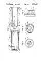
- FIG. 1is a plan view showing the standardized locking mechanism of the inner tube and outer shield of parent application invention prior to assembly as a medical safety-needled device;
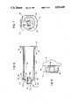
- FIG. 2is an end view of the outer shield of FIG. 1, taken along line 2--2 of FIG. 1, and showing a ratchet mechanism;
- FIG. 3is a side view of the ratchet mechanism of the outer shield shown in FIG. 1;
- FIG. 4is an end view of the outer shield taken along line 4--4 of FIG. 1;
- FIG. 5ais a longitudinal sectional view of the syringe embodiment of the parent application safety-needled invention where the outer shield is in a retracted position relative to the inner tube so that the needle is unshielded and ready for use;
- FIG. 5bis a longitudinal sectional view of the syringe embodiment of the parent application safety needled invention where the outer shield is in an extended position relative to the inner tube so that the contaminated needle is shielded;
- FIG. 6is a longitudinal sectional view of the inner tube of a blood collection tube holder embodiment of the parent application invention.
- FIG. 7is an end view of the inner tube of FIG. 6, taken along line 7--7 of FIG. 6;
- FIG. 8is a side view of the inner tube ratchet means shown in FIG. 6;
- FIG. 9ais plan view of the inner tube for the parent application prefilled syringe embodiment of the safety-needled invention.
- FIG. 9bis a plan view of the plunger arm for a prefilled syringe
- FIG. 10is a plan view of the front of the inner tube and the rear of the outer shield of the double-protrusion standardized medical safety-needled device of the invention prior to assembly;
- FIG. 11ais a partial longitudinal sectional view of the locking mechanisms of the double-protrusion three-groove syringe embodiment safety needled invention where the outer shield is in an extended position relative to the inner tube so that the contaminated needle is shielded;
- FIG. 11bis a partial longitudinal sectional view of the locking mechanisms of the double-protrusion two-groove syringe embodiment safety needled invention where the outer shield is in an extended position relative to the inner tube so that the contaminated needle is shielded;
- FIGS. 12a-12care partial longitudinal sectional views of second, third and fourth embodiments of the rear of the double-protrusion outer shield, a first embodiment being seen in FIG. 10;
- FIGS. 13a and 13bare partial longitudinal sectional views of a non-slit, single protrusion outer shield.
- FIGS. 1-9show the safety-needled device of the parent application with FIGS. 1-4 showing the basic structure of the safety-needled device, FIG. 5a showing the syringe embodiment with the needle exposed and ready for use, FIG. 5b showing the syringe embodiment after use with the outer shield in its forwardmost position in which the needle is covered, FIGS. 6-8 showing the blood collection tube holder embodiment, and FIG. 9 showing the prefilled syringe embodiment.
- FIGS. 10-12show an improvement to the locking devices of FIGS. 1-9 where the outer shield includes two axially spaced circumferential protrusions, while FIGS. 13a and 13b show a non-slit shield having a single protrusion.
- FIG. 10-12show an improvement to the locking devices of FIGS. 1-9 where the outer shield includes two axially spaced circumferential protrusions, while FIGS. 13a and 13b show a non-slit shield having a single protrusion.
- FIG. 13a and 13bshow
- FIGS. 11a and 11bshow interlocked shields and inner tubes after use of the needle, with FIG. 11a showing two forward grooves on the inner tube and FIG. 11b showing only one forward groove on the inner tube.
- FIGS. 12a-12cshow different embodiments of the two-protrusion arrangement of the outer shield where one or both of the protrusions may be either continuous or interrupted, and the outer shield may be slotted if desired.
- a safety medical devicecomprises two generally cylindrical pieces, a hollow inner tube 10 and an outer shield 12, both pieces typically being made of molded plastic or other acceptable material. Molded into the forward end of the outer surface of inner tube 10 is a ratchet assembly 14 including locking teeth which are shown in detail in FIGS. 7 and 8 with reference to the blood collection tube holder embodiment.
- the inner surface of the forward end of inner tube 10is also adapted to securely typically with a threaded structure to hold a standard hollow needle 16 shown with a removable needle cover 18 thereon.
- Inner tube 10is further provided with a cavity 22 into which drugs, pharmaceuticals, blood or other fluids may be aspirated and then forced through needle 16 into a body, or into which a blood collection tube may be placed so that blood from the body may be drawn.
- a flange 24is molded at the rearward end of inner tube 10 to act as a finger support while forcing the contents in the cavity into the body, or while withdrawing the needle from the patient, pharmaceutical vial, or other container.
- Circumferential grooves 36 and 38are formed in wall 42.
- An end wall 44extends from the forwardmost end of wall 42 and supports ratchet assembly 14 which is integral therewith and is described in more detail hereinafter with respect to the blood collection tube holder embodiment shown in FIGS. 6-8.
- a shoulder 46is formed, the rearward extension of shoulder 46 forming the forwardmost ledge 48 of circumferential groove 38.
- the rearmost ledge 50 of groove 38has a slightly smaller diameter than that of shoulder 46, and as wall 42 extends rearward from ledge 50, its outside diameter gradually decreases to form a sloped wall portion or ramp generally illustrated by 52.
- the wall 42is of constant diameter until it reaches slightly raised shoulder 54 which forms the forwardmost ledge 56 of circumferential groove 36.
- the forwardmost portion of flange 24forms the rearwardmost ledge of groove 36, and flange 24 has tine 57 for added finger support.
- the outer shield 12has an inside diameter which is slightly larger than the outer diameter of the inner tube 10.
- the outer shield 12is adapted to fit over inner tube 10 and to be slidable between a rearward position and a forward position (as respectively shown in FIGS. 5a and 5b for the syringe embodiment).
- the outer shield 12has a locking nozzle or ratchet means 26 molded into its inner surface at the forward end thereof, the locking nozzle including a plurality of locking notches, shown particularly in FIGS. 2 and 3.
- Locking nozzle 26is preferably annular in shape and is connected to the outer cylindrical wall 70 of shield 12 by end wall 72.
- a substantially annular opening 74 at the center of locking nozzle 26is adapted to permit a standard needle 16 to extend therethrough when the shield 13 is in its closed position.
- the locking nozzle 26engages the locking teeth in the rachet assembly 14 when the shield 12 is in its rearward (retracted) position, thereby preventing rotation of the outer shield 12 relative to the inner tube 10 during an injection or phlebotomy.
- a flanged safety ridge 28is formed near the forward end of outer shield 12 to assist the user in grasping the shield 12 and slidably moving it from its retracted position to its extended and locked position.
- the shield 12also has at its rearmost end a plurality of circumferentially spaced axial slots 30 which form there-between tabs 32, the tabs 32 being slightly flexible.
- Formed on the inner surface of tabs 32are a plurality of protrusions or lug members 34 (seen in FIG. 4) which are adapted to yieldingly engage a circumferential groove 36 preferably located at the rear end of inner tube 10 to thereby maintain the shield 12 in its retracted position (shown in FIG. 5a with respect to the syringe embodiment).
- the tabs 32are sufficiently flexible to permit the lug members 34 to be forced out of groove 36, and to permit the shield 12 to be moved forward manually to its extended or locked position (shown in FIG. 5b with respect to the syringe embodiment) in which the lug members 34 engage a second circumferential groove 38.
- the construction of the shield 12 and inner tube 10are such that the shield 12, when in the extended locked position with lug members 34 locked into groove 38, is extremely difficult to remove from the inner tube 10, while during assembly, the shield 12 is slipped over tube 10 without lug members 34 locking into groove 38.
- a plurality of notches or grooves 76are formed on the inside wall of locking nozzle 26.
- the notches 76are designed and sized to mesh with the raised teeth 66 extending from the outside of wall 60 of ratchet assembly 14 when shield 12 is positioned as shown in FIG. 5a with respect to the syringe embodiment.
- the meshing of the teeth 66 and notches 76prevents rotation of shield 12 relative to inner tube 10 which could be distracting to the medical personnel using the medical device.
- twenty-four notches 76are shown extending completely about the inside wall of locking nozzle 26, the exact number and shape may be varied and will be dependent on the size, shape and location of raised teeth 66. With raised teeth 66 on opposite sides of wall 60, the teeth 66 will mesh with notches 76 regardless of the relative circumferential alignment between inner tube 10 and outer shield 12.
- tab 32 and their corresponding lug members 34provide advantages in assembling the shielded medical device, and in moving the shield 12 from its unshielded (open) to its shielded (closed) position.
- the precise size and shape of lug members 34may be changed to suit the particular situation.
- FIGS. 5a and 5ba safety-needled syringe embodiment is shown, with like numbers indicating like parts.
- the outer shield 12is in its retracted position relative to the inner syringe tube 10 such that needle 16 is unshielded.
- Ratchet means 14 of the syringe tube 10, and locking nozzle 26 of the outer shield 12are engaged to prevent rotation of the shield relative to the inner syringe tube 10, while lug member 34 of tabs 32 are seated in circumferential groove 36.
- the inside of inner syringe tube 10as arranged to be generally cylindrical in shape, and at its forward end is shaped to accommodate the typically rubber end of a standard plunger 20.
- chamber 22 of the syringe tube 10is shown accepting plunger 20 which will either force the contents of chamber 22 through a small annular opening 58a in the ratchet assembly 14 and into and through the needle 16, or aspirate a fluid through the needle 16, the small annular opening 58a in the ratchet assembly, and into the chamber 22.
- graduated markings 40typically in cc measurements are placed on shield 12 for clear visibility, although since shield 12 is preferably transparent, the markings 40 may be placed on the syringe tube 10.
- the rubber end of plunger 20is seated at the accommodating front end of the chamber 22.
- shield 12is moved to the position indicated in FIG. 5b such that lugs 34 are seated in circumferential groove 38, and the needle 16 is shielded by shield 12.
- Shoulder 46 and ledge 50 of the syringe tube 10keep the lugs 34 of shield 12 firmly in place so that shield 12 cannot accidently retract or fall off of the syringe tube 10 and thereby reexpose the contaminated needle. It is of note with respect to FIGS. 5a and 5b, that the front end of the shield 12 extends further than is shown in FIG.
- the shield 12is essentially identical for all of the medical devices of the invention, its exact length and shape at the front end is dependent on the device with which it is to engage so as to prevent rotation.
- ratchet assembly 14has an annular opening 58b at the center thereof.
- the ratchet 14 assembly of inner tube 10 of the blood collection tube holderhas a cylindrical forwardly extending wall 60 which is provided at the inside circumference thereof with threads 62 or other means by which a standard hollow needle may be attached and communicate through annular opening 58b with cavity 22.
- inner tube 10is also provided with a rearwardly extending cylindrical wall 64 may be shaped to receive the forward end of a vacuum blood collection vial (not shown) in sealing engagement therebetween.
- the flange 28 on the outer shield 12not only provides a safety ridge for grasping and pushing shield 12, but may be used as a vacuum vial penetration indicator line.
- the self-sealing rubber end of the vacuum vialmay be axially inserted up until that point without the back point of the standard phlebotomy needle puncturing the same.
- the ratchet assembly 14 of the inner tube 10includes a plurality of raised teeth 66, which as seen in FIGS. 7 and 8 extend outwardly from the outside surface of wall 60 of rachet assembly 14.
- Five teeth 66are shown on diametrically opposed sides of wall 60, but the exact number and exact location of the teeth 66 may be varied.
- the teeth 66mesh with notches 76 of in the locking nozzle 26 of shield 12 to prevent rotation of shield 12 relative to inner tube 10 when the shield is in its retracted position.
- the inner tube 110 of the prefilled safety syringe embodiment of the inventionis seen in FIG. 9a, with the disposable plunger arm 105 seen in FIG. 9b. (In this embodiment corresponding elements will have corresponding numbers with the numbers of FIG. 9a being greater by one hundred).
- the inner tube 110 of FIG. 9acombines many of the standard features of a prefilled syringe with the afore-described inner tube features of the instant safety-needled invention.
- the inner tube 110is preferably made of or lined with glass.
- the medicated liquid 121is maintained in chamber 122 which is bounded by the cylindrical wall 142, a shaped metal cap 145 having an hermetic seal 147, and a rubber plunger seal 149 having a male threaded member 151 extending therefrom.
- the rear end of the inner tube 110is provided with a groove 161 for a preferably plastic snap-on flange 163, while the front end metal cap 145 is arranged to mate with a needle hub 165 having a ridge ring 167 on one end for mating with the metal cap 145, and means for accepting and holding a double pointed needle 116 on the other end.
- the needle 116is provided with a protective cover 118 which must be removed before an injection.
- a disposable plunger arm 105 seen in FIG. 9bis provided with a female thread member 181 which is screwed onto the male threaded member 151 of the inner tube 110 prior to injection. After mating, force may be applied to the plunger arm 105 so as to force the medicated liquid out through the double pointed needle 116.
- the inner tube 110also includes the safety-needled features.
- front and rear grooves 138 and 136into which the lugs of an outer shield may extend, with front groove 138 being deeper than rear groove 136.
- the outer surface of inner tube 110is provided with a shoulder 146 which prevents the outer shield from leaving the front groove 138, as well as a ramped surface 152 which helps provide the clicking/locking action.
- the open end of the outer shield 12is forced over the shoulder 46 (146) of the inner tube 10 (110), (FIG. 9 numbers not being listed hereafter).
- the lug members 34 attached to tabs 32initially contact the sloped wall portion 90 (FIG. 1) and the wall portion 90 forces the flexible tabs 32 outwardly in a fanlike manner.
- the lug members 34pass over and by raised shoulder 46, they instantaneously remain spread, both due to the contraction time required to reassume an unstressed position and due to the position assumed with the tabs angling away from wall 42 of tube 10, such that they can be quickly moved past groove 38 without falling into groove 38.
- the lug members 34press against ramp 52 which is of decreasing diameter, i.e., the tabs 32 are no longer flexed outwardly as a result of the reduced diameter of wall 42, and become parallel.
- the lug members 34 at the end of the shield 12ultimately pass over slightly raised shoulder 54, and lug members 34 fall into circumferential groove 36, where the shield 12 is substantially fixed as shown in FIG. 5a.
- circumferential groove 36is not as deep as circumferential groove 38, lug members 34 are not deeply seated in circumferential groove 36. Since tabs 32 are slightly flexible, it does not take a great deal of force to push the lugs 34 out of groove 36 and over raised shoulder 54. As the shield 12 is pushed forward, the lug members 34 contact ramp 52 in a direction in which the diameter of the wall 42 is increasing. This provides increased friction and tension on the tabs 32, i.e., the user is aware of the increase in force needed to keep the shield 12 moving forward.
- the lug members 34eventually fall into circumferential groove 38 with an audible click, providing a positive indication of locking beyond the visual indication. Because of its depth and because of the increased diameter of raised shoulder 46, groove 38 retains the shield fixed as shown in FIG. 5b. It is difficult to remove the shield once it is locked into circumferential groove 38, and a positive lock is assured, completely protecting medical personnel and others against needlestick injuries from the contaminated needle 16. The shielded medical device is then safely discarded in accord with established procedures.
- the shielded safety medical devices of FIGS. 1-9may be used in numerous circumstances and for differing purposes.
- a common usewould be by a phlebotomist (clinician) for obtaining blood samples from a patient.
- the phlebotomist (clinician)screws a capped sterile blood collection needle 16 into the threads 62 of inner tube 10.
- the phlebotomy needle(not shown) extends a short distance into cavity 22 of the inner tube 10, and a vacuum vial (not shown) having a rubber or plastic stopper is inserted into the tube 10 rather than a plunger.
- the stopper of the vacuum vialis penetrated by contact with the rearward extension of the needle, and blood is drawn into the vacuum vial through the needle which has been inserted into a vein of the patient.
- the needleis removed from the patient, the vacuum vial(s) now filled with a blood sample(s) is removed from the inner tube 10, and the phlebotomist (clinician) then slides the shield 12 over the inner tube 10 until the shield clicks and locks in place, thereby protecting personnel from injury from the contaminated needle or blood.
- the shielded blood collection tube holderis then safely disposed of, protecting against potential injuries and inadvertent contamination.
- the clinicianattaches the appropriate size needle to the syringe tube, removes the end cap and aspirates the required drug, medication, or blood into the syringe.
- the drug, medication, or other liquidis then administered to the patient directly by injection or through I.V. administration lines.
- the safety shieldis moved forward until the lugs of the tabs of the outer shield click and lock securely in the forward groove in the syringe tube. With such a procedure, the shield surrounds the needle as shown in FIG. 5b, and the syringe and contaminated needle may then be safely discarded.
- FIGS. 10-12various embodiments of improvements in the groove and protrusion locking arrangement of FIGS. 1-9 are seen.
- FIG. 10improvements are seen in both the protrusion arrangement of the shield and the front groove arrangement of the tube of FIG. 1 (like numerals indicating like parts).
- shield 12is seen to have two inwardly extending circumferential protrusions or lugs 34a and 34b.
- Protrusion 34ais a single continuous "lug" around the inner circumference of the shield 12 and is located forward of, and in relatively close proximity to protrusion 34b.
- Protrusion 34bas seen in FIG. 10, is comprised of several lugs 34b.
- section 234bwhich is part of the cylindrical wall 70 of the shield 12 rather than being separated by a slot (30) in the shield 12.
- the flexibility of the materials usedpermits the shield 12 to be formed without slots, provided inner tube 10 is arranged with a shoulder 46 over which the protrusions 34a and 34b must slide during assembly.
- inner tube 10is also altered in comparison to FIG. 1.
- two forward grooves 38a and 38bare provided into which protrusions (lugs) 34a and 34b may lock.
- groove 38b having front ledge 48b and rear ledge 50bis located near the beginning of the ramp 52 (i.e. at the end having the smallest diameter) on the outer surface of tube 10, while groove 38a having front ledge 48a and rear ledge 50a is located adjacent shoulder 46 and in relatively close proximity to groove 38b.
- groove 38ais of a slightly greater width than groove 38bl
- protrusion 34ahas a slightly greater width than protrusion 34b (and groove 38b).
- the double lockserves several purposes.
- the double lockprovides additional stability to the apparatus in the shielded position such that even large axial or torque forces will not cause the shield and tube to disengage. This stability is at least partially due to the fact that the shield 12 and tube 10 are engaged in two axial positions which doubles frictional forces and prevents rotation about a single plane.
- the double lockprevents the shield from sliding back into the retracted (unshielded) position.
- the double lockprovides an added measure of security in that should the first protrusion 34a disengage from the forward groove 38a with the shield moving in the forward direction, the second protrusion 34b will lock into forward groove 38a thereby continuing the protection against needlesticks by the contaminated needle.
- FIG. 12Aa second embodiment of the shield 12 shown in FIG. 10 are provided.
- FIG. 12Ashows inwardly extending circumferential protrusions (lugs) 34a and 34b which are both continuous (i.e. uninterrupted).
- the shield 12 of FIG. 12Ais also shown in FIG. 11B in its shielded (i.e. engaged) position with reference to inner tube 10 which is intended to be the equivalent of any of the inner tubes shown in FIGS. 1, 5A, 5B, 6, or 9.
- FIGS. 12B and 12Cadditional embodiments of the outer shield 12 are provided.
- the forward protrusion 34ais shown as being interrupted, with section 234a of wall 70 being seen therebetween.
- Protrusion 34bon the other hand is uninterrupted.
- both forward protrusion 34a and rear protrusion 34bare shown being interrupted.
- slots 30 in wall 70may be provided to cause the interruption of one or both of the protrusions.
- shields without slotsare shown in FIGS. 10, 11A, 11B, and 12A and 12B, it will be appreciated that the material of the shields must be flexible enough to permit the shield to extend over shoulder 46 of inner tube 12 so as to permit lugs 34a and 34b to pass over groove 38 (or grooves 38a and 38b) during assembly of the medical devices.
- a polypropylene or polyethylene plastichaving a thickness of 0.032 ⁇ 0.001 inches is utilized for the shield. The following preferred dimensions (in inches) are believed to function well in both assembly and usage:
- Inner diameter of the outer shield (12)0.816 ⁇ 0.002
- Diameter of front shoulder (46) of inner tube (10)0.810 ⁇ 0.001
- Front groove (38 or 38a) width0.070 ⁇ 0.002
- the width dimension of the second protrusion (34b) and the second front groove (38b)have not been set forth, as they could be the same as the first protrusion (34a) and the first front groove (38a), or they could be arranged such that the width of groove 38b (and hence protrusion 34b) is smaller than the width of protrusion 34a as suggested above. Regardless, with the provided diameter dimensions, the protrusions 34 of the shield will pass over the inner tube without stress as the inner diameter of the outer shield at the protrusions and the outer diameter of the non-ramped section of the inner tube are the same.
- protrusions 34Movement of the protrusions 34 along ramp 52 (or 54) during use will cause additional friction as the shield must be stressed in expansion. The movement of protrusions 34 into their respective grooves will therefore preferably provide an audible click as the shield reassumes its unstressed position.
- the inventionis intended to encompass single protrusion embodiments as seen in FIGS. 13a and 13b where no slits are provided in the rear of the outer shield.
- the protrusion 34can be placed in different locations, and may be interrupted (as seen in phantom) or not.
- embodiments having two and three grooveswere disclosed, four or more grooves could be utilized.
- the inner tubewas described as having a substantially cylindrical shape with conical ramps formed on either end, it will be appreciated that the entire outer surface of the inner tube could be ramped. Therefore, it will be apparent to those skilled in the art that yet other changes and modifications may be made to the invention as described without departing from the scope of the invention as so claimed.
Landscapes
- Health & Medical Sciences (AREA)
- Engineering & Computer Science (AREA)
- Heart & Thoracic Surgery (AREA)
- Vascular Medicine (AREA)
- Anesthesiology (AREA)
- Biomedical Technology (AREA)
- Environmental & Geological Engineering (AREA)
- Hematology (AREA)
- Life Sciences & Earth Sciences (AREA)
- Animal Behavior & Ethology (AREA)
- General Health & Medical Sciences (AREA)
- Public Health (AREA)
- Veterinary Medicine (AREA)
- Infusion, Injection, And Reservoir Apparatuses (AREA)
Abstract
Description
Claims (23)
Priority Applications (10)
| Application Number | Priority Date | Filing Date | Title |
|---|---|---|---|
| US07/224,920US4923445A (en) | 1988-03-01 | 1988-07-27 | Safety needled medical devices |
| US07/257,407US5088982A (en) | 1988-03-01 | 1988-10-13 | Safety winged needle medical devices |
| AU30716/89AAU3071689A (en) | 1988-03-01 | 1989-02-24 | Safety needled medical devices capable of one-handed manipulation |
| ES198989302013TES2046464T3 (en) | 1988-03-01 | 1989-02-28 | MEDICAL DEVICES WITH SAFETY NEEDLE. |
| DE89302013TDE68908584T2 (en) | 1988-03-01 | 1989-02-28 | Protected needle medical device. |
| KR1019890002380AKR910008024B1 (en) | 1988-03-01 | 1989-02-28 | One-handed adjustable needle medical device |
| EP89302013AEP0331452B1 (en) | 1988-03-01 | 1989-02-28 | Safety needled medical devices |
| CA000592266ACA1324546C (en) | 1988-03-01 | 1989-02-28 | Safety needles medical devices capable of one handed manipulation |
| JP1049737AJP2791082B2 (en) | 1988-03-01 | 1989-03-01 | Medical instrument with needle |
| US07/520,239US5066287A (en) | 1988-07-27 | 1990-05-07 | Safety multiple sample rear adapter assembly |
Applications Claiming Priority (2)
| Application Number | Priority Date | Filing Date | Title |
|---|---|---|---|
| US07/162,569US5059185A (en) | 1988-03-01 | 1988-03-01 | Safety needled medical devices |
| US07/224,920US4923445A (en) | 1988-03-01 | 1988-07-27 | Safety needled medical devices |
Related Parent Applications (1)
| Application Number | Title | Priority Date | Filing Date |
|---|---|---|---|
| US07/162,569Continuation-In-PartUS5059185A (en) | 1988-03-01 | 1988-03-01 | Safety needled medical devices |
Related Child Applications (4)
| Application Number | Title | Priority Date | Filing Date |
|---|---|---|---|
| US07/257,407Continuation-In-PartUS5088982A (en) | 1988-03-01 | 1988-10-13 | Safety winged needle medical devices |
| US07/303,588Continuation-In-PartUS5067945A (en) | 1988-03-01 | 1989-01-27 | Safety needled medical devices capable of one-handed manipulation |
| US07/416,927Continuation-In-PartUS5085639A (en) | 1988-03-01 | 1989-10-04 | Safety winged needle medical devices |
| US07/520,239Continuation-In-PartUS5066287A (en) | 1988-03-01 | 1990-05-07 | Safety multiple sample rear adapter assembly |
Publications (1)
| Publication Number | Publication Date |
|---|---|
| US4923445Atrue US4923445A (en) | 1990-05-08 |
Family
ID=26858871
Family Applications (1)
| Application Number | Title | Priority Date | Filing Date |
|---|---|---|---|
| US07/224,920Expired - LifetimeUS4923445A (en) | 1988-03-01 | 1988-07-27 | Safety needled medical devices |
Country Status (1)
| Country | Link |
|---|---|
| US (1) | US4923445A (en) |
Cited By (56)
| Publication number | Priority date | Publication date | Assignee | Title |
|---|---|---|---|---|
| WO1991004761A1 (en)* | 1989-10-04 | 1991-04-18 | Ryan Medical, Inc. | Safety winged needle medical devices |
| US5053018A (en)* | 1988-06-28 | 1991-10-01 | Sherwood Medical Company | Combined syringe and needle shield and method of manufacture |
| US5067945A (en)* | 1988-03-01 | 1991-11-26 | Ryan Medical, Inc. | Safety needled medical devices capable of one-handed manipulation |
| US5088982A (en)* | 1988-03-01 | 1992-02-18 | Ryan Medical, Inc. | Safety winged needle medical devices |
| US5088988A (en)* | 1988-06-28 | 1992-02-18 | Sherwood Medical Company | Combined dental syringe and needle shield |
| US5125908A (en)* | 1990-10-19 | 1992-06-30 | Cohen Milton J | Hypodermic syringe with protective holder |
| US5127910A (en)* | 1988-06-28 | 1992-07-07 | Sherwood Medical Company | Combined syringe and needle shield and method of manufacture |
| US5147326A (en)* | 1988-06-28 | 1992-09-15 | Sherwood Medical Company | Combined syringe and needle shield and method of manufacture |
| US5151088A (en)* | 1991-07-31 | 1992-09-29 | The Board Of Trustees Of The Leland Stanford Junior University | Safety needle and syringe assembly |
| US5154698A (en)* | 1990-10-19 | 1992-10-13 | Patrizio Compagnucci | Single use syringe incorporating a sliding protection cap for the needle |
| US5156599A (en)* | 1988-06-28 | 1992-10-20 | Sherwood Medical Company | Syringe and sliding locking needle shield |
| US5160326A (en)* | 1988-06-28 | 1992-11-03 | Sherwood Medical Company | Combined syringe and needle shield |
| US5169392A (en)* | 1988-06-28 | 1992-12-08 | Sherwood Medical Company | Combined syringe and needle shield and method of manufacture |
| US5201717A (en)* | 1990-12-05 | 1993-04-13 | Philip Wyatt | Safety enclosure |
| US5217437A (en)* | 1988-06-28 | 1993-06-08 | Sherwood Medical Company | Needle protecting device |
| USD344355S (en) | 1992-05-15 | 1994-02-15 | Sherwood Medical Company | Safety syringe |
| US5290255A (en)* | 1993-02-02 | 1994-03-01 | Vallelunga Anthony J | Apparatus for shielding a syringe needle |
| US5312370A (en)* | 1988-06-28 | 1994-05-17 | Sherwood Medical Company | Combined syringe and needle shield |
| US5498244A (en)* | 1993-09-22 | 1996-03-12 | American Home Products Corporation | Safety guard for medical instruments |
| US5720727A (en)* | 1994-09-06 | 1998-02-24 | Medisys Technologies, Inc. | Safety syringe |
| EP0830871A3 (en)* | 1996-09-20 | 1998-08-05 | Nissho Corporation | Winged needle assembly |
| US5846228A (en)* | 1996-11-14 | 1998-12-08 | Medisys Technologies, Inc. | Safety syringe for fluid collection |
| US5964735A (en)* | 1997-07-01 | 1999-10-12 | Medisys Technologies, Inc. | Fine needle aspiration safety syringe |
| US5993418A (en)* | 1998-02-24 | 1999-11-30 | Medisys Technologies, Inc. | Safety syringe |
| US6004296A (en)* | 1997-09-30 | 1999-12-21 | Becton Dickinson France, S.A. | Lockable safety shield assembly for a prefillable syringe |
| US6030366A (en)* | 1998-11-09 | 2000-02-29 | Safety Syringes, Inc. | Syringe guard system for a unit dose syringe |
| US6159184A (en)* | 1997-03-10 | 2000-12-12 | Safety Syringes, Inc. | Disposable self-shielding unit dose syringe guard |
| US6162197A (en)* | 1998-12-22 | 2000-12-19 | Mohammad; Owais | Retractable needle assembly and method of making the same |
| US6302868B1 (en) | 1998-12-22 | 2001-10-16 | Owais Mohammad | Retractable hypodermic needle assembly and method of making the same |
| US6319233B1 (en) | 1998-04-17 | 2001-11-20 | Becton, Dickinson And Company | Safety shield system for prefilled syringes |
| US6379337B1 (en) | 1998-12-22 | 2002-04-30 | Owais Mohammad M. B. B. S. | Retractable safety needles for medical applications |
| US6416323B1 (en)* | 2000-05-11 | 2002-07-09 | Safety Syringes, Inc. | Aspirating dental syringe with needle shield |
| US20020161337A1 (en)* | 2000-02-18 | 2002-10-31 | Shaw Derek J | Automatically operable safety shield system for syringes |
| US6626863B1 (en) | 2000-11-22 | 2003-09-30 | Nusaf, L.L.C. | Safety syringe |
| US6632201B1 (en) | 1999-11-17 | 2003-10-14 | Baxter International Inc. | Locking needle protector |
| US6669671B1 (en) | 1998-12-22 | 2003-12-30 | Owais Mohammad | Retractable needle with dual locking mechanisms |
| US6679864B2 (en) | 1998-04-17 | 2004-01-20 | Becton Dickinson And Company | Safety shield system for prefilled syringes |
| US6719730B2 (en) | 1998-04-17 | 2004-04-13 | Becton, Dickinson And Company | Safety shield system for prefilled syringes |
| US6776775B1 (en) | 1999-12-23 | 2004-08-17 | Owais Mohammad | Hypodermic syringe needle assembly and method of making the same |
| US20050049559A1 (en)* | 2002-08-09 | 2005-03-03 | Jean-Marie Mathias | Needle protector |
| US20050148944A1 (en)* | 2003-12-24 | 2005-07-07 | Hsin-Po Hsieh | Syringe safety sleeve |
| US20060089599A1 (en)* | 2004-10-27 | 2006-04-27 | Daniel Lynn | Blood donor needle assembly and cover |
| US20060100589A1 (en)* | 2004-08-10 | 2006-05-11 | Biotop Technology Co. Ltd. | Syringe safety sleeve |
| US20060200085A1 (en)* | 2005-02-15 | 2006-09-07 | Philip Watts | Tissue transfer cannula and connectors |
| US20060213793A1 (en)* | 2005-03-08 | 2006-09-28 | Christopher Brand | Syringe needle protector |
| US20060264825A1 (en)* | 2005-05-20 | 2006-11-23 | Safety Syringes, Inc. | Syringe with needle guard injection device |
| US20070049872A1 (en)* | 2005-07-01 | 2007-03-01 | Philip Watts | Syringe clip |
| US20070093755A1 (en)* | 2005-09-23 | 2007-04-26 | Koos David R | Cannula handle and storage system |
| US7985216B2 (en) | 2004-03-16 | 2011-07-26 | Dali Medical Devices Ltd. | Medicinal container engagement and automatic needle device |
| CN102335474A (en)* | 2010-07-26 | 2012-02-01 | 吴振文 | Syringe needle guard |
| US8376998B2 (en) | 2003-09-17 | 2013-02-19 | Elcam Medical Agricultural Cooperative Association Ltd. | Automatic injection device |
| US8603039B2 (en) | 2005-03-08 | 2013-12-10 | Christopher Brand | Syringe protector |
| US20190314577A1 (en)* | 2008-08-11 | 2019-10-17 | Tecpharma Licensing Ag | Automatic injection device for administering a fixed dose |
| WO2021094051A1 (en)* | 2019-11-15 | 2021-05-20 | Shl Medical Ag | Housing for a medicament delivery device |
| US11083841B2 (en) | 2002-08-09 | 2021-08-10 | Fenwal, Inc. | Needle protector, needle assembly and fluid processing set including the same |
| US12121709B1 (en) | 2019-03-22 | 2024-10-22 | Christopher Brand | Adaptable multiprocedural sharps safety device |
Citations (6)
| Publication number | Priority date | Publication date | Assignee | Title |
|---|---|---|---|---|
| US3890971A (en)* | 1973-10-23 | 1975-06-24 | Thomas A Leeson | Safety syringe |
| US4655751A (en)* | 1986-02-14 | 1987-04-07 | Harbaugh John T | Liquid dispensing and receiving syringe |
| US4702738A (en)* | 1986-05-22 | 1987-10-27 | Spencer Treesa A | Disposable hypodermic syringe and needle combination having retractable, accident preventing sheath |
| US4737144A (en)* | 1987-03-09 | 1988-04-12 | Choksi Pradip V | Syringe with selectively exposed and enveloped needle |
| US4758231A (en)* | 1987-04-27 | 1988-07-19 | Habley Medical Technology Corporation | Shielded safety syringe |
| US4816022A (en)* | 1987-12-07 | 1989-03-28 | Poncy George W | Hypodermic syringe with sliding cap |
- 1988
- 1988-07-27USUS07/224,920patent/US4923445A/ennot_activeExpired - Lifetime
Patent Citations (7)
| Publication number | Priority date | Publication date | Assignee | Title |
|---|---|---|---|---|
| US3890971A (en)* | 1973-10-23 | 1975-06-24 | Thomas A Leeson | Safety syringe |
| US4655751A (en)* | 1986-02-14 | 1987-04-07 | Harbaugh John T | Liquid dispensing and receiving syringe |
| US4702738A (en)* | 1986-05-22 | 1987-10-27 | Spencer Treesa A | Disposable hypodermic syringe and needle combination having retractable, accident preventing sheath |
| US4737144A (en)* | 1987-03-09 | 1988-04-12 | Choksi Pradip V | Syringe with selectively exposed and enveloped needle |
| US4758231A (en)* | 1987-04-27 | 1988-07-19 | Habley Medical Technology Corporation | Shielded safety syringe |
| US4790827A (en)* | 1987-04-27 | 1988-12-13 | Habley Medical Technology Corporation | Shielded safety syringe |
| US4816022A (en)* | 1987-12-07 | 1989-03-28 | Poncy George W | Hypodermic syringe with sliding cap |
Cited By (80)
| Publication number | Priority date | Publication date | Assignee | Title |
|---|---|---|---|---|
| US5085639A (en)* | 1988-03-01 | 1992-02-04 | Ryan Medical, Inc. | Safety winged needle medical devices |
| US5088982A (en)* | 1988-03-01 | 1992-02-18 | Ryan Medical, Inc. | Safety winged needle medical devices |
| US5067945A (en)* | 1988-03-01 | 1991-11-26 | Ryan Medical, Inc. | Safety needled medical devices capable of one-handed manipulation |
| US5522812A (en)* | 1988-06-28 | 1996-06-04 | Sherwood Medical Company | Combined dental syringe and needle shield |
| US5053018A (en)* | 1988-06-28 | 1991-10-01 | Sherwood Medical Company | Combined syringe and needle shield and method of manufacture |
| US5088988A (en)* | 1988-06-28 | 1992-02-18 | Sherwood Medical Company | Combined dental syringe and needle shield |
| US5217437A (en)* | 1988-06-28 | 1993-06-08 | Sherwood Medical Company | Needle protecting device |
| US5127910A (en)* | 1988-06-28 | 1992-07-07 | Sherwood Medical Company | Combined syringe and needle shield and method of manufacture |
| US5147326A (en)* | 1988-06-28 | 1992-09-15 | Sherwood Medical Company | Combined syringe and needle shield and method of manufacture |
| US5403287A (en)* | 1988-06-28 | 1995-04-04 | Sherwood Medical Company | Endcap and shield assembly for a shielded safety syringe |
| US5312370A (en)* | 1988-06-28 | 1994-05-17 | Sherwood Medical Company | Combined syringe and needle shield |
| US5156599A (en)* | 1988-06-28 | 1992-10-20 | Sherwood Medical Company | Syringe and sliding locking needle shield |
| US5160326A (en)* | 1988-06-28 | 1992-11-03 | Sherwood Medical Company | Combined syringe and needle shield |
| US5169392A (en)* | 1988-06-28 | 1992-12-08 | Sherwood Medical Company | Combined syringe and needle shield and method of manufacture |
| AU648224B2 (en)* | 1989-10-04 | 1994-04-14 | Winfield Medical | Safety winged needle medical devices |
| WO1991004761A1 (en)* | 1989-10-04 | 1991-04-18 | Ryan Medical, Inc. | Safety winged needle medical devices |
| US5154698A (en)* | 1990-10-19 | 1992-10-13 | Patrizio Compagnucci | Single use syringe incorporating a sliding protection cap for the needle |
| US5125908A (en)* | 1990-10-19 | 1992-06-30 | Cohen Milton J | Hypodermic syringe with protective holder |
| US5201717A (en)* | 1990-12-05 | 1993-04-13 | Philip Wyatt | Safety enclosure |
| US5151088A (en)* | 1991-07-31 | 1992-09-29 | The Board Of Trustees Of The Leland Stanford Junior University | Safety needle and syringe assembly |
| USD344355S (en) | 1992-05-15 | 1994-02-15 | Sherwood Medical Company | Safety syringe |
| US5290255A (en)* | 1993-02-02 | 1994-03-01 | Vallelunga Anthony J | Apparatus for shielding a syringe needle |
| US5498244A (en)* | 1993-09-22 | 1996-03-12 | American Home Products Corporation | Safety guard for medical instruments |
| US5720727A (en)* | 1994-09-06 | 1998-02-24 | Medisys Technologies, Inc. | Safety syringe |
| EP0830871A3 (en)* | 1996-09-20 | 1998-08-05 | Nissho Corporation | Winged needle assembly |
| US5928199A (en)* | 1996-09-20 | 1999-07-27 | Nissho Corporation | Winged needle assembly |
| US5846228A (en)* | 1996-11-14 | 1998-12-08 | Medisys Technologies, Inc. | Safety syringe for fluid collection |
| US6344032B1 (en) | 1997-03-10 | 2002-02-05 | Safety Syringes, Inc. | Disposable self-shielding unit dose syringe guard |
| US20050054987A1 (en)* | 1997-03-10 | 2005-03-10 | Safety Syringes, Inc. | Disposable self-shielding unit dose syringe guard |
| US20050033242A1 (en)* | 1997-03-10 | 2005-02-10 | Safety Syringes, Inc. | Disposable self-shielding unit dose syringe guard |
| US6159184A (en)* | 1997-03-10 | 2000-12-12 | Safety Syringes, Inc. | Disposable self-shielding unit dose syringe guard |
| US7041085B2 (en) | 1997-03-10 | 2006-05-09 | Safety Syrines, Inc. | Disposable self-shielding unit dose syringe guard |
| US5964735A (en)* | 1997-07-01 | 1999-10-12 | Medisys Technologies, Inc. | Fine needle aspiration safety syringe |
| US6638256B2 (en) | 1997-09-30 | 2003-10-28 | Becton Dickinson France S.A. | Lockable safety shield assembly for a prefillable syringe |
| US6193696B1 (en) | 1997-09-30 | 2001-02-27 | Becton Dickinson France, S.A. | Lockable safety shield assembly for a prefillable syringe |
| US6004296A (en)* | 1997-09-30 | 1999-12-21 | Becton Dickinson France, S.A. | Lockable safety shield assembly for a prefillable syringe |
| US5993418A (en)* | 1998-02-24 | 1999-11-30 | Medisys Technologies, Inc. | Safety syringe |
| US6679864B2 (en) | 1998-04-17 | 2004-01-20 | Becton Dickinson And Company | Safety shield system for prefilled syringes |
| US6319233B1 (en) | 1998-04-17 | 2001-11-20 | Becton, Dickinson And Company | Safety shield system for prefilled syringes |
| US20040106905A1 (en)* | 1998-04-17 | 2004-06-03 | Hubert Jansen | Safety shield system for prefilled syringes |
| US6719730B2 (en) | 1998-04-17 | 2004-04-13 | Becton, Dickinson And Company | Safety shield system for prefilled syringes |
| US6626864B2 (en) | 1998-04-17 | 2003-09-30 | Becton Dickinson France, S.A. | Safety shield system for prefilled syringes |
| US6685676B2 (en) | 1998-04-17 | 2004-02-03 | Becton Dickinson And Company | Safety shield system for prefilled syringes |
| US6030366A (en)* | 1998-11-09 | 2000-02-29 | Safety Syringes, Inc. | Syringe guard system for a unit dose syringe |
| US6162197A (en)* | 1998-12-22 | 2000-12-19 | Mohammad; Owais | Retractable needle assembly and method of making the same |
| US6669671B1 (en) | 1998-12-22 | 2003-12-30 | Owais Mohammad | Retractable needle with dual locking mechanisms |
| US6302868B1 (en) | 1998-12-22 | 2001-10-16 | Owais Mohammad | Retractable hypodermic needle assembly and method of making the same |
| US6379337B1 (en) | 1998-12-22 | 2002-04-30 | Owais Mohammad M. B. B. S. | Retractable safety needles for medical applications |
| US6632201B1 (en) | 1999-11-17 | 2003-10-14 | Baxter International Inc. | Locking needle protector |
| US6776775B1 (en) | 1999-12-23 | 2004-08-17 | Owais Mohammad | Hypodermic syringe needle assembly and method of making the same |
| US20020161337A1 (en)* | 2000-02-18 | 2002-10-31 | Shaw Derek J | Automatically operable safety shield system for syringes |
| US7118552B2 (en) | 2000-02-18 | 2006-10-10 | Astrazeneca Ab | Automatically operable safety shield system for syringes |
| US20040254540A1 (en)* | 2000-02-18 | 2004-12-16 | Astrazeneca Ab, A Sweden Corporation | Automatically operable safety shield system for syringes |
| US7500964B2 (en) | 2000-02-18 | 2009-03-10 | Astrazeneca Ab | Automatically operable safety shield system for syringes |
| US20070191783A1 (en)* | 2000-02-18 | 2007-08-16 | Astrazeneca Ab | Automatically Operable Safety Shield System for Syringes |
| US6416323B1 (en)* | 2000-05-11 | 2002-07-09 | Safety Syringes, Inc. | Aspirating dental syringe with needle shield |
| US6626863B1 (en) | 2000-11-22 | 2003-09-30 | Nusaf, L.L.C. | Safety syringe |
| US20050049559A1 (en)* | 2002-08-09 | 2005-03-03 | Jean-Marie Mathias | Needle protector |
| US11083841B2 (en) | 2002-08-09 | 2021-08-10 | Fenwal, Inc. | Needle protector, needle assembly and fluid processing set including the same |
| US7566327B2 (en) | 2002-08-09 | 2009-07-28 | Fenwal, Inc. | Needle protector |
| EP2650033A2 (en) | 2003-09-17 | 2013-10-16 | Elcam Medical Agricultural Cooperative Association Ltd. | Automatic injection device |
| US11623051B2 (en) | 2003-09-17 | 2023-04-11 | E3D Agricultural Cooperative Association Ltd. | Automatic injection device |
| US8376998B2 (en) | 2003-09-17 | 2013-02-19 | Elcam Medical Agricultural Cooperative Association Ltd. | Automatic injection device |
| US20050148944A1 (en)* | 2003-12-24 | 2005-07-07 | Hsin-Po Hsieh | Syringe safety sleeve |
| US7985216B2 (en) | 2004-03-16 | 2011-07-26 | Dali Medical Devices Ltd. | Medicinal container engagement and automatic needle device |
| US20060100589A1 (en)* | 2004-08-10 | 2006-05-11 | Biotop Technology Co. Ltd. | Syringe safety sleeve |
| US20060089599A1 (en)* | 2004-10-27 | 2006-04-27 | Daniel Lynn | Blood donor needle assembly and cover |
| US20060200085A1 (en)* | 2005-02-15 | 2006-09-07 | Philip Watts | Tissue transfer cannula and connectors |
| US8603039B2 (en) | 2005-03-08 | 2013-12-10 | Christopher Brand | Syringe protector |
| US20060213793A1 (en)* | 2005-03-08 | 2006-09-28 | Christopher Brand | Syringe needle protector |
| US8372044B2 (en) | 2005-05-20 | 2013-02-12 | Safety Syringes, Inc. | Syringe with needle guard injection device |
| US20060264825A1 (en)* | 2005-05-20 | 2006-11-23 | Safety Syringes, Inc. | Syringe with needle guard injection device |
| WO2007005902A3 (en)* | 2005-07-01 | 2007-03-29 | Bio Matrix Scient Group Inc | Syringe clip |
| US20070049872A1 (en)* | 2005-07-01 | 2007-03-01 | Philip Watts | Syringe clip |
| US20070093755A1 (en)* | 2005-09-23 | 2007-04-26 | Koos David R | Cannula handle and storage system |
| US20190314577A1 (en)* | 2008-08-11 | 2019-10-17 | Tecpharma Licensing Ag | Automatic injection device for administering a fixed dose |
| US11964132B2 (en)* | 2008-08-11 | 2024-04-23 | Ypsomed Ag | Automatic injection device for administering a fixed dose |
| CN102335474A (en)* | 2010-07-26 | 2012-02-01 | 吴振文 | Syringe needle guard |
| US12121709B1 (en) | 2019-03-22 | 2024-10-22 | Christopher Brand | Adaptable multiprocedural sharps safety device |
| WO2021094051A1 (en)* | 2019-11-15 | 2021-05-20 | Shl Medical Ag | Housing for a medicament delivery device |
Similar Documents
| Publication | Publication Date | Title |
|---|---|---|
| US4923445A (en) | Safety needled medical devices | |
| US5059185A (en) | Safety needled medical devices | |
| US5067945A (en) | Safety needled medical devices capable of one-handed manipulation | |
| EP0331452B1 (en) | Safety needled medical devices | |
| US4826491A (en) | Needle bearing medical device with three-position shield | |
| US4752290A (en) | Needle bearing medical device with three-position shield | |
| US5843041A (en) | Hypodermic needle guard and method to prevent needle stick injuries | |
| JP4298821B2 (en) | Disposable pen needle | |
| US10052438B2 (en) | Tamper evident needle guard for syringes | |
| JP3946324B2 (en) | Medical infusion device having a lockable safety shield | |
| US4737144A (en) | Syringe with selectively exposed and enveloped needle | |
| EP0941134B1 (en) | Lockable safety shield assembly for a prefillable syringe | |
| US5338303A (en) | Safety syringes | |
| EP0585391B1 (en) | Hypodermic needle guard and method to prevent needle stick injuries | |
| US5088988A (en) | Combined dental syringe and needle shield | |
| EP0713404B1 (en) | Disposable self-shielding aspirating syringe | |
| JP2927338B2 (en) | Syringe with safety needle shield | |
| US6017329A (en) | Hypodermic needle guard and method to prevent needle stick injuries | |
| AU2010202200B2 (en) | Single use syringe having safety shield | |
| EP1621222A1 (en) | Passive needle guard for syringes | |
| US5314414A (en) | Hypodermic needle guard and method to prevent needle stick injuries | |
| US6945958B2 (en) | Safety needle apparatus | |
| EP1358847B1 (en) | Needle holder with safety needle assembly | |
| WO1992018183A1 (en) | Combined syringe and needle shield | |
| WO2008118101A1 (en) | Safety guard for syringe needle |
Legal Events
| Date | Code | Title | Description |
|---|---|---|---|
| STCF | Information on status: patent grant | Free format text:PATENTED CASE | |
| AS | Assignment | Owner name:RYAN MEDICAL, INC., TENNESSEE Free format text:ASSIGNMENT OF ASSIGNORS INTEREST.;ASSIGNOR:RYAN, DANA W.;REEL/FRAME:005294/0257 Effective date:19900404 | |
| FPAY | Fee payment | Year of fee payment:4 | |
| FPAY | Fee payment | Year of fee payment:8 | |
| AS | Assignment | Owner name:WINFIELD INDUSTRIES, CALIFORNIA Free format text:MERGER;ASSIGNOR:RYAN MEDICAL, INC.;REEL/FRAME:009703/0460 Effective date:19930803 Owner name:WINFIELD MEDICAL A CORP. OF CA., CALIFORNIA Free format text:CHANGE OF NAME;ASSIGNOR:WINFIELD INDUSTRIES A CORP OF CA.;REEL/FRAME:009703/0412 Effective date:19961001 Owner name:MAXXIM MEDICAL, INC., FLORIDA Free format text:MERGER;ASSIGNOR:WINFIELD MEDICAL, A CORPORATION OF CALIFORNIA;REEL/FRAME:009703/0400 Effective date:19980811 | |
| AS | Assignment | Owner name:MAXXIM MEDICAL, INC., A CORP. OF DELAWARE, FLORIDA Free format text:MERGER;ASSIGNOR:WINFIELD MEDICAL, A CORP. OF CALIFORNIA;REEL/FRAME:010676/0688 Effective date:19980626 | |
| AS | Assignment | Owner name:MPS CAPITAL, INC., CALIFORNIA Free format text:ASSIGNMENT OF ASSIGNORS INTEREST;ASSIGNOR:MAXXIM MEDICAL, INC., A DELAWARE CORPORATION;REEL/FRAME:010977/0578 Effective date:20000523 | |
| FPAY | Fee payment | Year of fee payment:12 | |
| AS | Assignment | Owner name:PORTEX, INC., NEW HAMPSHIRE Free format text:ASSIGNMENT OF ASSIGNORS INTEREST;ASSIGNOR:MEDICAL PRODUCTS SPECIALISTS;REEL/FRAME:013663/0899 Effective date:20021220 | |
| AS | Assignment | Owner name:SMITHS MEDICAL ASD, INC., NEW HAMPSHIRE Free format text:CHANGE OF NAME;ASSIGNOR:PORTEX, INC.;REEL/FRAME:015044/0706 Effective date:20031103 |