US4923079A - Collapsible container - Google Patents
Collapsible containerDownload PDFInfo
- Publication number
- US4923079A US4923079AUS07/403,064US40306489AUS4923079AUS 4923079 AUS4923079 AUS 4923079AUS 40306489 AUS40306489 AUS 40306489AUS 4923079 AUS4923079 AUS 4923079A
- Authority
- US
- United States
- Prior art keywords
- door
- side walls
- latch member
- base
- latch
- Prior art date
- Legal status (The legal status is an assumption and is not a legal conclusion. Google has not performed a legal analysis and makes no representation as to the accuracy of the status listed.)
- Expired - Lifetime
Links
- 230000000712assemblyEffects0.000abstractdescription7
- 238000000429assemblyMethods0.000abstractdescription7
- 210000002105tongueAnatomy0.000description11
- 125000006850spacer groupChemical group0.000description4
- 238000004806packaging method and processMethods0.000description2
- 239000011347resinSubstances0.000description2
- 229920005989resinPolymers0.000description2
- 230000006835compressionEffects0.000description1
- 238000007906compressionMethods0.000description1
- 230000007812deficiencyEffects0.000description1
- 239000011152fibreglassSubstances0.000description1
- 230000003993interactionEffects0.000description1
- 239000011159matrix materialSubstances0.000description1
- 230000004048modificationEffects0.000description1
- 238000012986modificationMethods0.000description1
- 239000002991molded plasticSubstances0.000description1
Images


Classifications
- B—PERFORMING OPERATIONS; TRANSPORTING
- B65—CONVEYING; PACKING; STORING; HANDLING THIN OR FILAMENTARY MATERIAL
- B65D—CONTAINERS FOR STORAGE OR TRANSPORT OF ARTICLES OR MATERIALS, e.g. BAGS, BARRELS, BOTTLES, BOXES, CANS, CARTONS, CRATES, DRUMS, JARS, TANKS, HOPPERS, FORWARDING CONTAINERS; ACCESSORIES, CLOSURES, OR FITTINGS THEREFOR; PACKAGING ELEMENTS; PACKAGES
- B65D19/00—Pallets or like platforms, with or without side walls, for supporting loads to be lifted or lowered
- B65D19/02—Rigid pallets with side walls, e.g. box pallets
- B65D19/06—Rigid pallets with side walls, e.g. box pallets with bodies formed by uniting or interconnecting two or more components
- B65D19/18—Rigid pallets with side walls, e.g. box pallets with bodies formed by uniting or interconnecting two or more components made wholly or mainly of plastics material
- B—PERFORMING OPERATIONS; TRANSPORTING
- B65—CONVEYING; PACKING; STORING; HANDLING THIN OR FILAMENTARY MATERIAL
- B65D—CONTAINERS FOR STORAGE OR TRANSPORT OF ARTICLES OR MATERIALS, e.g. BAGS, BARRELS, BOTTLES, BOXES, CANS, CARTONS, CRATES, DRUMS, JARS, TANKS, HOPPERS, FORWARDING CONTAINERS; ACCESSORIES, CLOSURES, OR FITTINGS THEREFOR; PACKAGING ELEMENTS; PACKAGES
- B65D25/00—Details of other kinds or types of rigid or semi-rigid containers
- B65D25/005—Side walls formed with an aperture or a movable portion arranged to allow removal or insertion of contents
- B—PERFORMING OPERATIONS; TRANSPORTING
- B65—CONVEYING; PACKING; STORING; HANDLING THIN OR FILAMENTARY MATERIAL
- B65D—CONTAINERS FOR STORAGE OR TRANSPORT OF ARTICLES OR MATERIALS, e.g. BAGS, BARRELS, BOTTLES, BOXES, CANS, CARTONS, CRATES, DRUMS, JARS, TANKS, HOPPERS, FORWARDING CONTAINERS; ACCESSORIES, CLOSURES, OR FITTINGS THEREFOR; PACKAGING ELEMENTS; PACKAGES
- B65D2519/00—Pallets or like platforms, with or without side walls, for supporting loads to be lifted or lowered
- B65D2519/00004—Details relating to pallets
- B65D2519/00009—Materials
- B65D2519/00014—Materials for the load supporting surface
- B65D2519/00034—Plastic
- B—PERFORMING OPERATIONS; TRANSPORTING
- B65—CONVEYING; PACKING; STORING; HANDLING THIN OR FILAMENTARY MATERIAL
- B65D—CONTAINERS FOR STORAGE OR TRANSPORT OF ARTICLES OR MATERIALS, e.g. BAGS, BARRELS, BOTTLES, BOXES, CANS, CARTONS, CRATES, DRUMS, JARS, TANKS, HOPPERS, FORWARDING CONTAINERS; ACCESSORIES, CLOSURES, OR FITTINGS THEREFOR; PACKAGING ELEMENTS; PACKAGES
- B65D2519/00—Pallets or like platforms, with or without side walls, for supporting loads to be lifted or lowered
- B65D2519/00004—Details relating to pallets
- B65D2519/00009—Materials
- B65D2519/00049—Materials for the base surface
- B65D2519/00069—Plastic
- B—PERFORMING OPERATIONS; TRANSPORTING
- B65—CONVEYING; PACKING; STORING; HANDLING THIN OR FILAMENTARY MATERIAL
- B65D—CONTAINERS FOR STORAGE OR TRANSPORT OF ARTICLES OR MATERIALS, e.g. BAGS, BARRELS, BOTTLES, BOXES, CANS, CARTONS, CRATES, DRUMS, JARS, TANKS, HOPPERS, FORWARDING CONTAINERS; ACCESSORIES, CLOSURES, OR FITTINGS THEREFOR; PACKAGING ELEMENTS; PACKAGES
- B65D2519/00—Pallets or like platforms, with or without side walls, for supporting loads to be lifted or lowered
- B65D2519/00004—Details relating to pallets
- B65D2519/00009—Materials
- B65D2519/00154—Materials for the side walls
- B65D2519/00174—Plastic
- B—PERFORMING OPERATIONS; TRANSPORTING
- B65—CONVEYING; PACKING; STORING; HANDLING THIN OR FILAMENTARY MATERIAL
- B65D—CONTAINERS FOR STORAGE OR TRANSPORT OF ARTICLES OR MATERIALS, e.g. BAGS, BARRELS, BOTTLES, BOXES, CANS, CARTONS, CRATES, DRUMS, JARS, TANKS, HOPPERS, FORWARDING CONTAINERS; ACCESSORIES, CLOSURES, OR FITTINGS THEREFOR; PACKAGING ELEMENTS; PACKAGES
- B65D2519/00—Pallets or like platforms, with or without side walls, for supporting loads to be lifted or lowered
- B65D2519/00004—Details relating to pallets
- B65D2519/00258—Overall construction
- B65D2519/00398—Overall construction reinforcements
- B65D2519/00402—Integral, e.g. ribs
- B65D2519/00422—Integral, e.g. ribs on the walls
- B—PERFORMING OPERATIONS; TRANSPORTING
- B65—CONVEYING; PACKING; STORING; HANDLING THIN OR FILAMENTARY MATERIAL
- B65D—CONTAINERS FOR STORAGE OR TRANSPORT OF ARTICLES OR MATERIALS, e.g. BAGS, BARRELS, BOTTLES, BOXES, CANS, CARTONS, CRATES, DRUMS, JARS, TANKS, HOPPERS, FORWARDING CONTAINERS; ACCESSORIES, CLOSURES, OR FITTINGS THEREFOR; PACKAGING ELEMENTS; PACKAGES
- B65D2519/00—Pallets or like platforms, with or without side walls, for supporting loads to be lifted or lowered
- B65D2519/00004—Details relating to pallets
- B65D2519/00258—Overall construction
- B65D2519/00492—Overall construction of the side walls
- B65D2519/00502—Overall construction of the side walls whereby at least one side wall is made of two or more pieces
- B—PERFORMING OPERATIONS; TRANSPORTING
- B65—CONVEYING; PACKING; STORING; HANDLING THIN OR FILAMENTARY MATERIAL
- B65D—CONTAINERS FOR STORAGE OR TRANSPORT OF ARTICLES OR MATERIALS, e.g. BAGS, BARRELS, BOTTLES, BOXES, CANS, CARTONS, CRATES, DRUMS, JARS, TANKS, HOPPERS, FORWARDING CONTAINERS; ACCESSORIES, CLOSURES, OR FITTINGS THEREFOR; PACKAGING ELEMENTS; PACKAGES
- B65D2519/00—Pallets or like platforms, with or without side walls, for supporting loads to be lifted or lowered
- B65D2519/00004—Details relating to pallets
- B65D2519/00547—Connections
- B65D2519/00577—Connections structures connecting side walls, including corner posts, to each other
- B65D2519/00582—Connections structures connecting side walls, including corner posts, to each other structures intended to be disassembled, i.e. collapsible or dismountable
- B65D2519/00611—Connections structures connecting side walls, including corner posts, to each other structures intended to be disassembled, i.e. collapsible or dismountable side walls maintained connected to each other by means of auxiliary locking elements, e.g. spring loaded locking pins
- B—PERFORMING OPERATIONS; TRANSPORTING
- B65—CONVEYING; PACKING; STORING; HANDLING THIN OR FILAMENTARY MATERIAL
- B65D—CONTAINERS FOR STORAGE OR TRANSPORT OF ARTICLES OR MATERIALS, e.g. BAGS, BARRELS, BOTTLES, BOXES, CANS, CARTONS, CRATES, DRUMS, JARS, TANKS, HOPPERS, FORWARDING CONTAINERS; ACCESSORIES, CLOSURES, OR FITTINGS THEREFOR; PACKAGING ELEMENTS; PACKAGES
- B65D2519/00—Pallets or like platforms, with or without side walls, for supporting loads to be lifted or lowered
- B65D2519/00004—Details relating to pallets
- B65D2519/00547—Connections
- B65D2519/00636—Connections structures connecting side walls to the pallet
- B65D2519/00641—Structures intended to be disassembled
- B65D2519/00646—Structures intended to be disassembled by means of hinges
- B65D2519/00656—Structures intended to be disassembled by means of hinges separately formed
- B—PERFORMING OPERATIONS; TRANSPORTING
- B65—CONVEYING; PACKING; STORING; HANDLING THIN OR FILAMENTARY MATERIAL
- B65D—CONTAINERS FOR STORAGE OR TRANSPORT OF ARTICLES OR MATERIALS, e.g. BAGS, BARRELS, BOTTLES, BOXES, CANS, CARTONS, CRATES, DRUMS, JARS, TANKS, HOPPERS, FORWARDING CONTAINERS; ACCESSORIES, CLOSURES, OR FITTINGS THEREFOR; PACKAGING ELEMENTS; PACKAGES
- B65D2519/00—Pallets or like platforms, with or without side walls, for supporting loads to be lifted or lowered
- B65D2519/00004—Details relating to pallets
- B65D2519/00547—Connections
- B65D2519/00636—Connections structures connecting side walls to the pallet
- B65D2519/00641—Structures intended to be disassembled
- B65D2519/00661—Structures intended to be disassembled side walls maintained connected to pallet by means of auxiliary locking elements, e.g. spring loaded locking pins
- B—PERFORMING OPERATIONS; TRANSPORTING
- B65—CONVEYING; PACKING; STORING; HANDLING THIN OR FILAMENTARY MATERIAL
- B65D—CONTAINERS FOR STORAGE OR TRANSPORT OF ARTICLES OR MATERIALS, e.g. BAGS, BARRELS, BOTTLES, BOXES, CANS, CARTONS, CRATES, DRUMS, JARS, TANKS, HOPPERS, FORWARDING CONTAINERS; ACCESSORIES, CLOSURES, OR FITTINGS THEREFOR; PACKAGING ELEMENTS; PACKAGES
- B65D2519/00—Pallets or like platforms, with or without side walls, for supporting loads to be lifted or lowered
- B65D2519/00004—Details relating to pallets
- B65D2519/00736—Details
- B65D2519/00805—Means for facilitating the removal of the load
- B—PERFORMING OPERATIONS; TRANSPORTING
- B65—CONVEYING; PACKING; STORING; HANDLING THIN OR FILAMENTARY MATERIAL
- B65D—CONTAINERS FOR STORAGE OR TRANSPORT OF ARTICLES OR MATERIALS, e.g. BAGS, BARRELS, BOTTLES, BOXES, CANS, CARTONS, CRATES, DRUMS, JARS, TANKS, HOPPERS, FORWARDING CONTAINERS; ACCESSORIES, CLOSURES, OR FITTINGS THEREFOR; PACKAGING ELEMENTS; PACKAGES
- B65D2519/00—Pallets or like platforms, with or without side walls, for supporting loads to be lifted or lowered
- B65D2519/00004—Details relating to pallets
- B65D2519/00736—Details
- B65D2519/00865—Collapsible, i.e. at least two constitutive elements remaining hingedly connected
- B65D2519/00875—Collapsible, i.e. at least two constitutive elements remaining hingedly connected collapsible side walls
- B65D2519/009—Collapsible, i.e. at least two constitutive elements remaining hingedly connected collapsible side walls whereby all side walls are hingedly connected to the base panel
- B—PERFORMING OPERATIONS; TRANSPORTING
- B65—CONVEYING; PACKING; STORING; HANDLING THIN OR FILAMENTARY MATERIAL
- B65D—CONTAINERS FOR STORAGE OR TRANSPORT OF ARTICLES OR MATERIALS, e.g. BAGS, BARRELS, BOTTLES, BOXES, CANS, CARTONS, CRATES, DRUMS, JARS, TANKS, HOPPERS, FORWARDING CONTAINERS; ACCESSORIES, CLOSURES, OR FITTINGS THEREFOR; PACKAGING ELEMENTS; PACKAGES
- B65D2519/00—Pallets or like platforms, with or without side walls, for supporting loads to be lifted or lowered
- B65D2519/00004—Details relating to pallets
- B65D2519/00736—Details
- B65D2519/00935—Details with special means for nesting or stacking
- B65D2519/00955—Details with special means for nesting or stacking stackable
- B65D2519/00965—Details with special means for nesting or stacking stackable when loaded
- B65D2519/00975—Details with special means for nesting or stacking stackable when loaded through the side walls
Definitions
- the inventionrelates to containers of the type used for packaging and shipping goods in bulk and is collapsible to reduce the space required for them to be shipped after use by stacking the empty compacted containers.
- Durable collapsible or foldable container assemblieshave been used by the shipping and packaging industries.
- An example of such containersis disclosed in U.S. Pat. No. 4,591,065 to Dennis M. Foy.
- This foldable containerincludes a molded plastic base having four side walls extending vertically upward from each side of the base. The walls are vertically spaced for folding one side wall over the base and another side wall over the former one and into overlapping vertical spaced relationship to one another.
- the hinges on two of the side wallshave an associated link having slots therein for allowing the side wall to move vertically relative to the base for locking and unlocking the walls from one another.
- the tops of the side wallshave projections for coacting with legs extending from the base to relatively position and stack the containers one upon another.
- the baseonly has legs extending downwardly and outwardly from it, and no means is provided for guiding the forks of a forked lift into the base for raising and lowering the container assembly.
- the tops of the side wallsmust include a projection which coacts with the legs to stack the container assembly on the tops of the side walls only.
- a foldable container assemblyincludes a base having a plurality of sides, at least one side wall extending vertically upwardly from each side of the base with the tops of the side walls all being aligned in a horizontal plane.
- a wall hinge meansinterconnects each of the side walls to the base with the wall hinge means for a first side wall being in a vertically spaced horizontal plane from the wall hinge means for a second side wall for folding the first and second side walls over the base and into overlapping vertically spaced relationship to one another.
- the assemblyis characterized by the base being generally convex and including a rigid top member and a support means connected to the top member for supporting the top member upon a support surface and defining channels therein to accommodate a lifting means in the openings and for guiding the lifting means into the openings and for inserting the base within the opening of another assembly formed by the side walls in the vertical position to allow vertical stacking of the container assemblies one upon another.
- the subject inventionincludes a means for defining channels and guiding the forks of a lifting means into the channels.
- the subject inventionallows the base of the container assembly to be inserted partially within the opening formed by the side walls in the vertical position of another assembly to allow vertical stacking of the container assemblies upon one another.
- FIG. 1is a perspective view of the container with the walls in a vertically locked position
- FIG. 2is a perspective view wherein a door in the first wall has been unlocked and folded outward;
- FIG. 3is a perspective view of the folded container taken from substantially the same angle as FIG. 2;
- FIG. 4is an enlarged plan view of the wall locking means with adjacent side walls locked in the vertical position
- FIG. 5is an enlarged elevational view of the wall locking means in the locked position
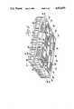
- FIG. 6is a perspective view of the underside of the base for stacking the container.
- FIG. 7is an enlarged exploded view of the hinge means illustrating the interaction of the tongue and groove hinge.
- FIG. 8is a cross-sectional view take substantially along lines 8--8 of FIG. 7.
- FIG. 9is a cross-sectional view taken substantially along lines 9--9 of FIG. 7.
- FIG. 10is a cross-sectional view taken substantially along lines 10--10 of FIG. 7.
- FIG. 11is an enlarged top plan view of the door locking means with the door locked in the vertical closed position.
- a foldable or collapsible container assemblyis generally shown at 10 in FIG. 1.
- the 12, assembly 10includes a base, generally indicated at and a plurality of sides or side walls 14, 16, 18, 20 with at least one side wall 14, 16, 18, 20 extending vertically upwardly from each side of the base 12.
- the tops 22 of the side walls 14, 16, 18, 20are all aligned in a horizontal plane as shown in FIG. 1.
- the assembly 10includes wall hinge means, generally indicated at 24, interconnecting each of the side walls 14, 16, 18, 20 to the base 12 with the wall hinge means 24 for a first side wall 14, being in a vertically spaced horizontal plane from the wall hinge means 24 for a second side wall 16 for folding the first 14 and second 16 side walls over the base 12 and into overlapping vertically spaced relationship to one another.
- the wall hinge means 24includes a series of tongue and grooves along the bottom edge of the side wall 14, 16, 18, 20 and the top edge of the base 12 wherein the tongues of the side wall 14, 16, 18, 20 are disposed in the grooves of the base 12 and visa versa, as shown in FIG. 7.
- the wall hinge means 24further includes a series of hinge holes or apertures 26 along the bottom edge of the side wall 14, 16, 18, 20 and the top edge of the base 12 in the tongue and groove arrangement.
- a rod 28is disposed in the apertures 26 of the side wall 14, 16, 18, 20 and the base 12 and has a lock washer 30 on each end thereof to secure the tongues in the grooves and to allow pivotal movement of the side wall 14, 16, 18, 20 relative to the base 12.
- a rod 28is disposed in a series of apertures 26 along the bottom edge of the side wall 14, 16, 18, 20 and the top edge of the base 12 to allow pivotal movement of the side wall 14, 16, 18, 20 relative to the base 12.
- the rod 28may be a protruded fiber glass rod with a resin-enriched surface.
- the resin-enriched surface of the rodprolongs the life of the rod and prevents wear.
- the rod 28is essentially unbreakable and is capable of sustaining substantial deformation without failure.
- the rod 28resists deformation because the stresses applied to it are isolated due to the tongue and groove arrangement. In other words, each tongue may apply a stress from internal or external forces only over a small cross section of the rod 28.
- the rod 28resists the stresses over a small cross section and is substantially rigid as disposed in the hinge means 24. This adds strength to the hinge.
- the tongue and groove of the hinge means 24is arranged such that the thickness of the hinge means 24 at the base 12 is greater than the thickness of the hinge means 24 at the side wall 14, 16, 18, 20. More specifically, the tongue and groove of the base 12 may be as much as twice as thick or more than the tongue and groove of the side wall 14, 16, 18, 20. This arrangement is much stronger than previous hinges employed in collapsible containers and transforms an area of weakness into a strength.
- FIGS. 8, 9 and 10illustrate the relationships between the apertures 26 in the base 12 and the rod 28 at various points along the tongue and groove hinge means 24.
- the wall hinge means 24 for the first 14 and second 16 side wallslie in vertically spaced horizontal planes, whereas the wall hinge means 24 for the third 18 and fourth 20 of the side walls are in the same horizontal plane above the horizontal plane of the wall hinge means 24 for the second side wall 16.
- the third and fourth side walls 18, 20extend from their associated hinge means 24 to the tops 22 thereof a distance less than one half the distance between the wall hinge means 24 for the third and fourth side walls 18, 20. That is to say, the opposing side walls 18 and 20 do not overlap when folded downward, instead lying flat on top of the folded walls 14 and 16 as illustrated in FIG. 3.
- the assembly 10includes interconnecting means, generally indicated at 32, for releaseably interconnecting the side edge of each side wall 14, 16, 18, 20 to the side edge of the adjacent side wall when in the vertical position.
- the interconnecting means 32includes a plurality of vertically spaced lugs 34 disposed along one edge of one side wall and a lug receiving openings 36 disposed along the adjacent edge of the adjacent side wall opposite the spaced lugs 34.
- the side walls 18, 20are raised to the vertical position and on either side wall 14 or 16 is directly pivotally rotated about the axis of the rod 28 of the wall hinge means 24 to the vertical position where the lug receiving openings 36 engage the spaced lugs 34.
- the side walls 14, 16, 18, 20are pivoted from the folded position on the base 12 about the axis of the rod 28 to the vertical position and vice versa.
- the side walls 14, 16, 18, 20have planar interior sheets 38 with ribs generally indicated at 40 extending outwardly therefrom and in spaced relationship with respect to each other.
- the ribs 40are disposed closer to one another at the tops 22 of the side walls 14, 16, 18, 20 and at the base 12 to provide greater support to the side walls, 14, 16, 18, 20 near these areas. More specifically, the ribs 40 include horizontal ribs 41 and vertical ribs 43.
- the horizontal ribs 41are disposed vertically closer together at the tops 22 and at the base 12 and spaced further apart from one another near the middle of the side walls 14, 16, 18, 20.
- the vertical ribs 43are disposed horizontally closer together at the tops 22 and at the base 12 and spaced further apart from one another near the middle of the side walls 14, 16, 18, 20. Further, a side wall 14, 16, 18, 20 may include diagonal ribs 45 extending diagonally across a portion of the walls 14, 16, 18, 20. Together, the ribs 40, 41, 43 and 45 form a support matrix for providing greater support at the tops 22 of the side walls 14, 16, 18, 20 and near the base 12 of the container assembly 10 and insures the structural integrity of the assembly 10 under various loading stresses.
- the assembly 10includes wall locking means generally indicated at 42, for releaseably locking the side edge of each side wall 14, 16, 18, 20 to the side edge of the adjacent side wall when in the vertical position.
- the wall locking means 42includes a latch member 44 connected to at least one edge of the side wall 14, 16, 18, 20 by a fastening means such as welds 45 and having a projection 46 extending outwardly from one side thereof.
- the side walls 14, 16,include a latch member 44 connected to both edges or sides of the side walls 14, 16.
- the wall locking means 42includes a longitudinal groove or slot 48 along the edge of an adjacent side wall opposite the projection 46 of the latch member 44.
- the side walls 18, 20include a longitudinal groove 48 along each side edge of the side walls 18, 20.
- the latch member 44also includes a cavity portion 50.
- a biasing means 52is disposed in the cavity portion 50 of the latch member 44 for biasing the projection 46 of the latch member 44 into engagement and disengagement with the groove 48.
- the biasing means 52comprises a spring 52.
- the latch member 44further includes a flange 54 acting as a handle to allow a person to manually actuate the latch member 44 by hand. In operation, the latch member 44 is slideably moved by engaging the flange 54 and moving the latch member 44 along the side wall 14, 16 in a plane substantially parallel to the side wall 14, 16 to move the projection 46 into engagement and disengagement with the groove 48 of the adjacent side wall 18, 20. This is known in the art as a "slam latch".
- the assembly 10further includes a door means, generally indicated at 58, disposed in an opening 60 in at least one of the side walls 14, 16, 18, 20 for opening and closing the opening 60 to allow access to the inside of the container assembly 10 through the side walls 14, 16, 18, 20 when the side walls 14, 16, 18, 20 are in the vertical position.
- a door meansgenerally indicated at 58, disposed in an opening 60 in at least one of the side walls 14, 16, 18, 20 for opening and closing the opening 60 to allow access to the inside of the container assembly 10 through the side walls 14, 16, 18, 20 when the side walls 14, 16, 18, 20 are in the vertical position.
- the door means 58includes a door 62 disposed within the opening 60 of the side wall 14, 16, 18, 20 and a door hinge means, generally indicated at 64, connected to one, preferably the bottom, edge of the door 62 and the adjacent edge, preferably the bottom, of the opening 60 for allowing pivotal movement of the door 62 relative to the side wall 14, 16, 18, 20.
- the door hinge means 64includes a flexible C-shaped member 66 to allow the door 62 to pivot outwardly with respect to the side wall 14, 16, 18, 20 as illustrated in FIG. 2.
- the flexible C-shaped memberhas one 66 flange connected to the bottom of the opening 60 and the other flange connected to the bottom of the door 62 to allow the door 62 to be pivotally rotated from a closed position within the side wall 14, 16, 18, 20 to an open position outwardly from the container assembly 10.
- the door 62When the door 62 is in the fully open position, it extends downwards in a vertical plane which is adjacent the vertical plane of the side wall, 14, 16, 18, 20.
- the door 62When the door 62 is in the fully open position, it extends downwardly in a vertical plane which is adjacent the vertical plane of the side wall 14, 16, 18, 20.
- the assembly 10includes a door locking means, generally indicated at 68, for releaseably engaging the door 62 with the side wall 14, 16, 18, 20 in a locked condition to prevent pivotal movement of the door 62 relative to the side wall 14, 16, 18, 20 and releaseably disengaging the door 62 from the side wall 14, 16, 18, 20 in an unlocked condition to allow pivotal movement of the door 62 relative to the side wall 14, 16, 18, 20.
- the door locking means 68 as shown in FIG. 11is similar to the wall locking means 42.
- the door locking means 68includes a latch member 70 mounted on the door 62 and having projections 72 extending outwardly from one side thereof and slideably disposed in a groove 74 of the opening 60.
- the projections 72are biased outwardly from the door 62 and into engagement with the groove 74 by a biasing means 73 such as a spring.
- the spring 73is disposed between the door 62 and the latch member 70 and exerts a force on the latch member 70 to urge the projections 72 outward.
- the projection 72include a chamfer 75 on its inward side nearest to the inside of the container assembly (10) and a flat side 77 which extends parallel to the side wall of the groove 74. Both the chamfer 75 and the flat side 77 are disposed at the distal end of the projection 72 and opposite one another.
- the door locking means 68includes a snap-in feature attendant upon closing the door 62 but not upon opening the door 62. The chamfer facilitates the automatic retraction of the projection 72 upon closing the door 62 without manual manipulation of the latch member 70.
- the door 62includes a door latch member 70 on each side of the door 62 and a adjacent groove 74 along each side of the opening 60.
- the disposition of the latch member 70 on either side of the door 62allows an operator to unlock the door 62 and control the door 62 as it opens without need to readjust or remove his grip on the door.
- the latch 70was disposed on a side wall 14, 16, 18, 20 contrary to the subject invention, and the groove 74 located in the door 62, when an operator unlocked the door 62 by manipulating the latch member 70, the door would fall open freely and possibly strike the operator.
- the operatoris less likely to control the door as it opens because his hands are located on the latch 70 of the side wall 14, 16, 18, 20 and not on the door 62 of the present invention.
- the present inventionavoids this occurrence.
- the operation of the door locking means 68is similar to the wall locking means 42.
- the opening 60includes a flange 76 acting as a stop to prevent pivotal movement of the door 62 past the side wall 14, 16, 18, 20 to the inside of the container assembly 10.
- the base 12 of the assembly 10is generally convexed with respect to a flat support surface. Said another way, the base 12 is not generally flat or substantially parallel to a flat planner support surface.
- the base 12includes a rigid top member 80 and a support means, generally indicated at 82, connected to the top member 80 for supporting the top member 80 upon a support surface and defining channels 84 therein for guiding the forks of a lifting means such as a forked lift into the channels 84 and for inserting the base 12 within the perimeter or opening formed by the side walls 14, 16, 18, 20 in the vertical position of another assembly 10 to allow vertical stacking of the container assemblies one upon another.
- the support means 82includes a corner support member 86 at each of the four corners of the top member 80 and a perimeter support element 88 near the perimeter of the top member 80 about midway between adjacent pairs of corner support elements 86, and a center support element 90 near the center of the top member 80.
- support elements 86, 88, and 90are similar to legs extending downwardly from the top member 80 to space the top member 80 from a support surface.
- the support means 82includes a spacer means, generally indicated at 92, for integrally interconnecting the corner support elements 86 and the perimeter support elements 88 and the center support element 90 to form a bottom member similar to the top member 80.
- the base 12is similar to a pallet.
- the spacer means 92structurally reinforces and supports the support elements 86, 88, 90 and forms a bottom member. Said another way, the spacer means 92 interconnects a corner support element 86 with a perimeter support element 88 and a center support element 90 with the perimeter support element 88 to form a bottom member substantially similar to the top member.
- the spacer means 92includes a strip member 94 being defined as a plate.
- the strip member 94is substantially the same width as the support elements 86, 88, and 90 to form four rectangular-like openings in the bottom member. Both the top member 80 and strip member 94 include longitudinal slots 96 therein.
- the strip member 94includes a flange 98 along one edge thereof extending downwardly and outwardly from the strip member 94 for abutting the interior edge of the side walls 14, 16, 18, 20 when the side walls 14, 16, 18, 20 are in the vertical position for vertically stacking the container assemblies 10 one upon another.
- the flange 98 of the strip member 94forms a perimeter similar to the opening formed when the side walls 14, 16, 18, 20 are in the vertical position so that the flange 98 fits inside the opening to prevent movement of the container assembly 10 when vertically stacking the container assemblies 10 upon one another. Accordingly, any combination of folded and unfolded containers may be stacked upon one another.
- the corner support element 86 and the perimeter support element 88define a pair of forked channels 84 for receiving and guiding the forks of a forked lift for mechanically raising and lowering the container assembly 10.
- the corner support elements 86 and the perimeter support elements 88each have planner exterior side surfaces 100 along the perimeter of the top member 80 and parallel interior surfaces 102 extending diagonally inwardly from the exterior side surfaces 100 to guide the forks of the forked lift in the channels 84.
- the flange 98includes a chamfer 104 to guide the forks of the forked lift upwardly into the channels 84.
- the door 62when the door 62 is in the fully open position, the door partially blocks the channels 84 and thereby prevents the container assembly 10 from being moved when the door is in the open position.
- any combination of folded and unfolded containersmay be stacked upon one another.
Landscapes
- Engineering & Computer Science (AREA)
- Mechanical Engineering (AREA)
- Rigid Containers With Two Or More Constituent Elements (AREA)
Abstract
Description
This application is a continuation of application Ser. No. 328,749, filed 3/22/89, now abandoned, which is a continuation of 022,996 filed 3/6/87, now abandoned.
The invention relates to containers of the type used for packaging and shipping goods in bulk and is collapsible to reduce the space required for them to be shipped after use by stacking the empty compacted containers.
Durable collapsible or foldable container assemblies have been used by the shipping and packaging industries. An example of such containers is disclosed in U.S. Pat. No. 4,591,065 to Dennis M. Foy. This foldable container includes a molded plastic base having four side walls extending vertically upward from each side of the base. The walls are vertically spaced for folding one side wall over the base and another side wall over the former one and into overlapping vertical spaced relationship to one another. The hinges on two of the side walls have an associated link having slots therein for allowing the side wall to move vertically relative to the base for locking and unlocking the walls from one another. Also, the tops of the side walls have projections for coacting with legs extending from the base to relatively position and stack the containers one upon another.
The deficiency in such containers is that the base only has legs extending downwardly and outwardly from it, and no means is provided for guiding the forks of a forked lift into the base for raising and lowering the container assembly. Moreover, the tops of the side walls must include a projection which coacts with the legs to stack the container assembly on the tops of the side walls only.
A foldable container assembly includes a base having a plurality of sides, at least one side wall extending vertically upwardly from each side of the base with the tops of the side walls all being aligned in a horizontal plane. A wall hinge means interconnects each of the side walls to the base with the wall hinge means for a first side wall being in a vertically spaced horizontal plane from the wall hinge means for a second side wall for folding the first and second side walls over the base and into overlapping vertically spaced relationship to one another. The assembly is characterized by the base being generally convex and including a rigid top member and a support means connected to the top member for supporting the top member upon a support surface and defining channels therein to accommodate a lifting means in the openings and for guiding the lifting means into the openings and for inserting the base within the opening of another assembly formed by the side walls in the vertical position to allow vertical stacking of the container assemblies one upon another.
Accordingly, the subject invention includes a means for defining channels and guiding the forks of a lifting means into the channels. The subject invention allows the base of the container assembly to be inserted partially within the opening formed by the side walls in the vertical position of another assembly to allow vertical stacking of the container assemblies upon one another.
Other advantages of the present invention will be readily appreciated as the same becomes better understood by reference to the following detailed description when considered in connection with the accompanying drawings wherein:
FIG. 1 is a perspective view of the container with the walls in a vertically locked position;
FIG. 2 is a perspective view wherein a door in the first wall has been unlocked and folded outward;
FIG. 3 is a perspective view of the folded container taken from substantially the same angle as FIG. 2;
FIG. 4 is an enlarged plan view of the wall locking means with adjacent side walls locked in the vertical position;
FIG. 5 is an enlarged elevational view of the wall locking means in the locked position; and
FIG. 6 is a perspective view of the underside of the base for stacking the container.
FIG. 7 is an enlarged exploded view of the hinge means illustrating the interaction of the tongue and groove hinge.
FIG. 8 is a cross-sectional view take substantially alonglines 8--8 of FIG. 7.
FIG. 9 is a cross-sectional view taken substantially along lines 9--9 of FIG. 7.
FIG. 10 is a cross-sectional view taken substantially alonglines 10--10 of FIG. 7.
FIG. 11 is an enlarged top plan view of the door locking means with the door locked in the vertical closed position.
A foldable or collapsible container assembly is generally shown at 10 in FIG. 1. The 12,assembly 10 includes a base, generally indicated at and a plurality of sides orside walls side wall base 12. Thetops 22 of theside walls assembly 10 includes wall hinge means, generally indicated at 24, interconnecting each of theside walls base 12 with the wall hinge means 24 for afirst side wall 14, being in a vertically spaced horizontal plane from the wall hinge means 24 for a second side wall 16 for folding the first 14 and second 16 side walls over thebase 12 and into overlapping vertically spaced relationship to one another.
The wall hinge means 24 includes a series of tongue and grooves along the bottom edge of theside wall base 12 wherein the tongues of theside wall base 12 and visa versa, as shown in FIG. 7. The wall hinge means 24 further includes a series of hinge holes orapertures 26 along the bottom edge of theside wall base 12 in the tongue and groove arrangement. Arod 28 is disposed in theapertures 26 of theside wall base 12 and has a lock washer 30 on each end thereof to secure the tongues in the grooves and to allow pivotal movement of theside wall base 12. In other words, arod 28 is disposed in a series ofapertures 26 along the bottom edge of theside wall base 12 to allow pivotal movement of theside wall base 12. Therod 28 may be a protruded fiber glass rod with a resin-enriched surface. The resin-enriched surface of the rod prolongs the life of the rod and prevents wear. Therod 28 is essentially unbreakable and is capable of sustaining substantial deformation without failure. As disposed in the hinge means 24, however, therod 28 resists deformation because the stresses applied to it are isolated due to the tongue and groove arrangement. In other words, each tongue may apply a stress from internal or external forces only over a small cross section of therod 28. Therod 28 resists the stresses over a small cross section and is substantially rigid as disposed in the hinge means 24. This adds strength to the hinge. Further, the tongue and groove of the hinge means 24 is arranged such that the thickness of the hinge means 24 at thebase 12 is greater than the thickness of the hinge means 24 at theside wall base 12 may be as much as twice as thick or more than the tongue and groove of theside wall apertures 26 in thebase 12 and therod 28 at various points along the tongue and groove hinge means 24.
The wall hinge means 24 for the first 14 and second 16 side walls lie in vertically spaced horizontal planes, whereas the wall hinge means 24 for the third 18 and fourth 20 of the side walls are in the same horizontal plane above the horizontal plane of the wall hinge means 24 for the second side wall 16. The third andfourth side walls tops 22 thereof a distance less than one half the distance between the wall hinge means 24 for the third andfourth side walls opposing side walls walls 14 and 16 as illustrated in FIG. 3.
Theassembly 10 includes interconnecting means, generally indicated at 32, for releaseably interconnecting the side edge of eachside wall lugs 34 disposed along one edge of one side wall and alug receiving openings 36 disposed along the adjacent edge of the adjacent side wall opposite the spacedlugs 34. In operation, theside walls side wall 14 or 16 is directly pivotally rotated about the axis of therod 28 of the wall hinge means 24 to the vertical position where thelug receiving openings 36 engage the spacedlugs 34. In other words, theside walls base 12 about the axis of therod 28 to the vertical position and vice versa.
Theside walls ribs 40 are disposed closer to one another at thetops 22 of theside walls base 12 to provide greater support to the side walls, 14, 16, 18, 20 near these areas. More specifically, theribs 40 include horizontal ribs 41 andvertical ribs 43. The horizontal ribs 41 are disposed vertically closer together at thetops 22 and at thebase 12 and spaced further apart from one another near the middle of theside walls vertical ribs 43 are disposed horizontally closer together at thetops 22 and at thebase 12 and spaced further apart from one another near the middle of theside walls side wall diagonal ribs 45 extending diagonally across a portion of thewalls ribs side walls base 12 of thecontainer assembly 10 and insures the structural integrity of theassembly 10 under various loading stresses.
Theassembly 10 includes wall locking means generally indicated at 42, for releaseably locking the side edge of eachside wall latch member 44 connected to at least one edge of theside wall welds 45 and having aprojection 46 extending outwardly from one side thereof. Preferably, theside walls 14, 16, include alatch member 44 connected to both edges or sides of theside walls 14, 16. The wall locking means 42 includes a longitudinal groove orslot 48 along the edge of an adjacent side wall opposite theprojection 46 of thelatch member 44. Preferably, theside walls longitudinal groove 48 along each side edge of theside walls latch member 44 also includes acavity portion 50. A biasing means 52 is disposed in thecavity portion 50 of thelatch member 44 for biasing theprojection 46 of thelatch member 44 into engagement and disengagement with thegroove 48. The biasing means 52 comprises aspring 52. Thelatch member 44 further includes aflange 54 acting as a handle to allow a person to manually actuate thelatch member 44 by hand. In operation, thelatch member 44 is slideably moved by engaging theflange 54 and moving thelatch member 44 along theside wall 14, 16 in a plane substantially parallel to theside wall 14, 16 to move theprojection 46 into engagement and disengagement with thegroove 48 of theadjacent side wall
Theassembly 10 further includes a door means, generally indicated at 58, disposed in anopening 60 in at least one of theside walls opening 60 to allow access to the inside of thecontainer assembly 10 through theside walls side walls container assembly 10 is stacked one upon another, the door means 58 disposed in theopening 60 of theside wall container assembly 10 through theside walls side walls door 62 disposed within theopening 60 of theside wall door 62 and the adjacent edge, preferably the bottom, of theopening 60 for allowing pivotal movement of thedoor 62 relative to theside wall
The door hinge means 64 includes a flexible C-shaped member 66 to allow thedoor 62 to pivot outwardly with respect to theside wall opening 60 and the other flange connected to the bottom of thedoor 62 to allow thedoor 62 to be pivotally rotated from a closed position within theside wall container assembly 10. When thedoor 62 is in the fully open position, it extends downwards in a vertical plane which is adjacent the vertical plane of the side wall, 14, 16, 18, 20. When thedoor 62 is in the fully open position, it extends downwardly in a vertical plane which is adjacent the vertical plane of theside wall
Theassembly 10 includes a door locking means, generally indicated at 68, for releaseably engaging thedoor 62 with theside wall door 62 relative to theside wall door 62 from theside wall door 62 relative to theside wall latch member 70 mounted on thedoor 62 and havingprojections 72 extending outwardly from one side thereof and slideably disposed in agroove 74 of theopening 60. Theprojections 72 are biased outwardly from thedoor 62 and into engagement with thegroove 74 by a biasing means 73 such as a spring. Thespring 73 is disposed between thedoor 62 and thelatch member 70 and exerts a force on thelatch member 70 to urge theprojections 72 outward. Theprojection 72 include a chamfer 75 on its inward side nearest to the inside of the container assembly (10) and aflat side 77 which extends parallel to the side wall of thegroove 74. Both the chamfer 75 and theflat side 77 are disposed at the distal end of theprojection 72 and opposite one another. When thedoor 62 is in the vertical, upright, closed and locked position, the door may only be opened by manually disengaging the door locking means 68. This may occur by pulling thelatch member 70 to place thespring 73 in further compression until theprojection 72 has been retracted out of thegroove 74. Thedoor 62 may then be opened. However, closing thedoor 62 requires only that the door be shut with a sufficient force to drive theprojection 72 into retraction when the chamfer 75 of theprojection 72 comes into contact with theopening 60. Said another way, the door locking means 68 includes a snap-in feature attendant upon closing thedoor 62 but not upon opening thedoor 62. The chamfer facilitates the automatic retraction of theprojection 72 upon closing thedoor 62 without manual manipulation of thelatch member 70. After theprojection 72 has been retracted and thedoor 62 placed in the fully upright and closed position, theprojection 72 is urged into thegroove 74 by thespring 73. Preferably, thedoor 62 includes adoor latch member 70 on each side of thedoor 62 and aadjacent groove 74 along each side of theopening 60. The disposition of thelatch member 70 on either side of thedoor 62 allows an operator to unlock thedoor 62 and control thedoor 62 as it opens without need to readjust or remove his grip on the door. Said another way, if thelatch 70 was disposed on aside wall groove 74 located in thedoor 62, when an operator unlocked thedoor 62 by manipulating thelatch member 70, the door would fall open freely and possibly strike the operator. The operator is less likely to control the door as it opens because his hands are located on thelatch 70 of theside wall door 62 of the present invention. The present invention avoids this occurrence. The operation of the door locking means 68 is similar to the wall locking means 42. Theopening 60 includes aflange 76 acting as a stop to prevent pivotal movement of thedoor 62 past theside wall container assembly 10.
Thebase 12 of theassembly 10 is generally convexed with respect to a flat support surface. Said another way, thebase 12 is not generally flat or substantially parallel to a flat planner support surface. Thebase 12 includes a rigidtop member 80 and a support means, generally indicated at 82, connected to thetop member 80 for supporting thetop member 80 upon a support surface and definingchannels 84 therein for guiding the forks of a lifting means such as a forked lift into thechannels 84 and for inserting thebase 12 within the perimeter or opening formed by theside walls assembly 10 to allow vertical stacking of the container assemblies one upon another. The support means 82 includes acorner support member 86 at each of the four corners of thetop member 80 and aperimeter support element 88 near the perimeter of thetop member 80 about midway between adjacent pairs ofcorner support elements 86, and acenter support element 90 near the center of thetop member 80. In other words, supportelements top member 80 to space thetop member 80 from a support surface. The support means 82 includes a spacer means, generally indicated at 92, for integrally interconnecting thecorner support elements 86 and theperimeter support elements 88 and thecenter support element 90 to form a bottom member similar to thetop member 80. Hence, thebase 12 is similar to a pallet. The spacer means 92 structurally reinforces and supports thesupport elements corner support element 86 with aperimeter support element 88 and acenter support element 90 with theperimeter support element 88 to form a bottom member substantially similar to the top member. The spacer means 92 includes astrip member 94 being defined as a plate. Thestrip member 94 is substantially the same width as thesupport elements top member 80 andstrip member 94 includelongitudinal slots 96 therein. Thestrip member 94 includes aflange 98 along one edge thereof extending downwardly and outwardly from thestrip member 94 for abutting the interior edge of theside walls side walls container assemblies 10 one upon another. In other words, theflange 98 of thestrip member 94 forms a perimeter similar to the opening formed when theside walls flange 98 fits inside the opening to prevent movement of thecontainer assembly 10 when vertically stacking thecontainer assemblies 10 upon one another. Accordingly, any combination of folded and unfolded containers may be stacked upon one another.
Thecorner support element 86 and theperimeter support element 88 define a pair of forkedchannels 84 for receiving and guiding the forks of a forked lift for mechanically raising and lowering thecontainer assembly 10. Thecorner support elements 86 and theperimeter support elements 88 each have planner exterior side surfaces 100 along the perimeter of thetop member 80 and parallelinterior surfaces 102 extending diagonally inwardly from the exterior side surfaces 100 to guide the forks of the forked lift in thechannels 84. Theflange 98 includes achamfer 104 to guide the forks of the forked lift upwardly into thechannels 84. However, when thedoor 62 is in the fully open position, the door partially blocks thechannels 84 and thereby prevents thecontainer assembly 10 from being moved when the door is in the open position.
Accordingly, any combination of folded and unfolded containers may be stacked upon one another.
The invention has been described in an illustrative manner, and it is to be understood that the terminology which has been used is intended to be in the nature of words of description rather than of limitation.
Obviously, many modifications and variations of the present invention are possible in light of the above teachings. It is, therefore, to be understood that within the scope of the appended claims wherein reference numerals are merely for convenience and are not to be in any way limiting, the invention may be practiced otherwise than as specifically described.
Claims (11)
1. A foldable container assembly (10) comprising: a base (12) having a plurality of sides walls (14,16,18,20) extending vertically upward from each side of said base (12) at least one of said walls (14,16,18,20) including an opening (60) therein, said opening (60) including an open-ended top side, a horizontal bottom side, a pair of vertical sides extending from said open-ended top side to a point between said open-ended top side and said horizontal bottom side of said opening (60) and a pair of inwardly angled sides extending from the point between said top side and said bottom side of said opening (60) and which terminates and forms an intersection at said horizontal bottom side and characterized by a pair of ribs forming an apex at the intersection of said inwardly angled side and said downwardly bottom side of said opening (60), said pair of ribs diverging from said apex and terminating at the bottom of said side walls (14,16,18,20) and for increasing the structural integrity of said opening (60) and for providing strength to said container (10) at a crucial, load-bearing area.
2. The container (10) as set forth in claim 1 further characterized by a pair of diagonal ribs extending outwardly from the intersection of said vertical side and said inwardly extending sides of said opening (60) at the point between said top side and said bottom side of said opening (60) and the outside edge of said side walls (14,16,18,20) for increasing the structural integrity of said opening (60) and for providing strength to said container (10) at the intersection of said vertical side and said inwardly extending side of said opening (60) at the point between said top side and said bottom side of said opening (60).
3. A foldable container assembly (10) comprising:
a base (12) having a plurality of sides, at least one side wall (14,16,18,20) extending vertically upward from each side of said base (12) and including wall hinge means (24) interconnecting each of said side walls (14,16,18,20) to said base (12);
locking means (42,68) disposed on said container assembly (10) for releasably locking one portion of the container assembly (10) to the side edge of an adjacent side wall when in the vertical position;
said locking means (42,68) including a fixed member mounted to said container assembly (10) and a latch member (44,70) slideably moveable with respect to said fixed member between latched and unlatched positions with respect to an adjacent side wall (14,16,18,20), said latch member (44,70) including a latch flange extending away from said container assembly (10) at one end of said latch member (44,70) for engagement by an operator for moving said latch member (44,70) from said latched to said unlatched position and a stop flange extending inwardly toward said container assembly (10) and at the opposite end of said latch member (44,70) to limit the travel of said latch member (44,70) with respect to said fixed member in said latched position, said fixed member including a base flange extending away from said container assembly (10) and in parallel spaced relationship with respect to said stop flange to define a cavity portion therebetween;
said assembly characterized by including a biasing means (52,73) disposed within said cavity portion and acting between said base flange of said fixed member and said stop flange of said latch member (44,70) to bias said latch member (44,70) to said latched position with respect to said adjacent side walls (14,16,18,20).
4. A foldable container assembly (10) comprising;
a base (12) having a plurality of sides, at least one side wall (14,16,18,20) extending vertically upward from each side of said base (12) and including wall hinge means (24) interconnecting each of said side walls (14,16,18,20) to said base (12);
wall locking means (42) for releaseably locking the side edge of each side wall (14,16,18,20) to the side edge of an adjacent side wall when in the vertical position;
said wall locking means (42) including a fixed member mounted to at least one edge of said side wall (14,16,18,20) and a latch member (44) slideably moveable with respect to said fixed member between latched and unlatched positions with respect to an adjacent side wall (14,16,18,20), said latch member (44) including a latch flange (54) extending away from said side wall (14,16,18,20) at one end of said latch member (44) for engagement by an operator for moving said latch member (44) from said latch to said unlatched position and a stop flange extending inwardly toward said side walls (14,16,18,20) and at the opposite end of said latch member (44) to limit the travel of said latch member (44) with respect to said fixed member and in said latched position, said fixed member including a base flange extending away from said side walls (14,16,18,20) and in parallel spaced relationship with respect to said stop flange to define a cavity portion (50) therebetween;
said assembly characterized by including a biasing means (52) disposed within said cavity portion (50) and acting between said base flange of said fixed member and said stop flange of said latch member (44) to bias said latch member (44) to said latched position with respect to said adjacent side walls (14,16,18,20).
5. An assembly (10) as set forth in claim 4 further characterized by said wall locking means (42) including a longitudinal groove (48) in the edge of an adjacent side wall (14,16,18,20) said latch member (44) having a projection (46) extending outwardly from the terminal end thereof opposite said latch flange (54), said projection (46) being slideably disposed in said groove (48) when said side wall (14,16,18,20) is in the vertical locked position.
6. An assembly as set forth in claim 5 further characterized by said projection (46) including a chamfer disposed on the distal end of said projection (46), said biasing means (52) and said chamfer on said projection (46) allowing said side wall (14,16,18,20) to be moved from a collapsed position and snapped into an upright position without manual manipulation of said latch member (44) from said latched to said unlatched position by movement of said latch flange (54) of said wall locking means (42).
7. An assembly as set forth in claim 6 further characterized by said side walls (14,16,18,20) having planar interior sheet (38) and the ribs (46) extending outwardly therefrom and in spaced relationship with respect to each other to form a plurality of recesses in said side walls (14,16,18,20), said fixed member of said wall latching means (42) mounted flush to said planar sheet (38) within one of said recesses.
8. A foldable container assembly (10) comprising;
a base (12) having a plurality of sides, side walls (14,16,18,20) extending vertically upward from each side of said base (12) and including wall hinge means (24) interconnecting each of said side walls (14,16,18,20) to said base (12), at least one of said side walls (14,16,18,20) including an opening (60) therein, and including a door (62) disposed in said opening (60) of said side walls (14,16,18,20) for opening an closing said opening (60) to allow axis to the inside of the container assembly (10) through said side walls (14,16,18,20) when said side walls (14,16,18,20) are in the vertical position;
door locking means (68) disposed on said door (62) for releaseably engaging said door (62) with said side walls (14,16,18,20) in a locked position to prevent pivotal movement of said door (62) relative to said side walls (14,16,18,20) and releaseably disengaging said door (62) from said side walls (14,16,18,20) in an unlocked position to allow pivotal movement of said door (62) relative to said side walls (14,16,18,20);
said door locking means (68) including a fixed member mounted to at least one edge of said door (62) and a latch member (70) slideably moveable with respect to said fixed member between latched and unlatched positions with respect to an adjacent side wall (14,16,18,20), said latch member (70) including a latch flange extending away from said door (62) at one end of said latch member (70) for engagement by an operator for moving said latch member (70) from said latched to said unlatched position and a stop flange extending inwardly toward said door (62) and at the opposite end of said latch member (70) to limit the travel of said latch member (70) with respect to said fixed member and in said latched position, said fixed member including a base flange extending away from said door (62) and in parallel space relationship with respect to said stop flange to define a cavity portion therebetween;
said assembly characterized by including biasing means (73) disposed within said cavity portion and acting between said base flange of said fixed member and said stop flange of said latch member (70) to bias said latch member (70) to said latched position with respect to said adjacent side walls (14,16,18,20).
9. An assembly (10) as set forth in claim 8 further characterized by said door locking means (68) including a longitudinal groove (74) in the edge of an adjacent side wall (14,16,18,20), said latch member (70) having a projection (72) extending outwardly from the terminal end thereof opposite said latch flange, said projection (72) being slideably disposed in said groove (74) when said door (62) is in the vertical locked position.
10. An assembly as set forth in claim 9 further characterized by said projection (72) including a chamfer (75) disposed on the distal end of said projection (72), said biasing means (73) and said chamber (75) on said projection (72) allowing said door (62) to be moved from an open position and snapped into an upright closed position without manual manipulation of said latch member (70) from said latch to said unlatched position by movement of said latch flange of said door locking means (68).
11. An assembly (10) as set forth in claim 10 further characterized by said door (62) having planar interior sheets and ribs extending outwardly therefrom and in spaced relationship with respect to each other to form a plurality of recesses in said door (62), said fixed member of said door locking means (68) mounted flush to said planar sheets within one of said recesses.
Priority Applications (1)
| Application Number | Priority Date | Filing Date | Title |
|---|---|---|---|
| US07/403,064US4923079A (en) | 1987-03-06 | 1989-09-01 | Collapsible container |
Applications Claiming Priority (2)
| Application Number | Priority Date | Filing Date | Title |
|---|---|---|---|
| US2299687A | 1987-03-06 | 1987-03-06 | |
| US07/403,064US4923079A (en) | 1987-03-06 | 1989-09-01 | Collapsible container |
Related Parent Applications (1)
| Application Number | Title | Priority Date | Filing Date |
|---|---|---|---|
| US07328749Continuation | 1989-03-22 |
Publications (1)
| Publication Number | Publication Date |
|---|---|
| US4923079Atrue US4923079A (en) | 1990-05-08 |
Family
ID=26696601
Family Applications (1)
| Application Number | Title | Priority Date | Filing Date |
|---|---|---|---|
| US07/403,064Expired - LifetimeUS4923079A (en) | 1987-03-06 | 1989-09-01 | Collapsible container |
Country Status (1)
| Country | Link |
|---|---|
| US (1) | US4923079A (en) |
Cited By (72)
| Publication number | Priority date | Publication date | Assignee | Title |
|---|---|---|---|---|
| US5094356A (en)* | 1990-11-13 | 1992-03-10 | Buckhorn Material Handling Group, Inc. | Knock down bulk container |
| US5199592A (en)* | 1989-03-15 | 1993-04-06 | Perstorp Extec, Inc. | Container with latchable hinged sidewall gate |
| US5398835A (en)* | 1993-11-29 | 1995-03-21 | Blinstrub; Robert M. | Collapsible material handling container having improved corner interlock |
| US5467885A (en)* | 1993-11-29 | 1995-11-21 | Blinstrub; Robert M. | Collapsible material handling container |
| EP0690004A1 (en) | 1993-11-29 | 1996-01-03 | Otto Industries, Inc. | Collapsible container |
| US5586675A (en)* | 1993-11-29 | 1996-12-24 | General Electric Company | Reinforced material handling container |
| US6003707A (en)* | 1997-09-18 | 1999-12-21 | Rensch; Eberhard G. | Receptacle |
| US6015056A (en)* | 1997-12-19 | 2000-01-18 | Rehrig Pacific Company | Collapsible container |
| USD446392S1 (en) | 1999-12-27 | 2001-08-14 | Rehrig Pacific Company | Storage container |
| US6293418B1 (en)* | 1999-12-09 | 2001-09-25 | Norseman Plastics Limited | Collapsible container |
| USD452614S1 (en) | 2000-10-28 | 2002-01-01 | Rehrig Pacific Company | Collapsible container |
| US6386388B1 (en) | 1999-12-27 | 2002-05-14 | Rehrig Pacific Company | Container |
| USD458753S1 (en) | 2000-09-21 | 2002-06-18 | Rehrig Pacific Co. | Container |
| US6409041B1 (en) | 2000-09-21 | 2002-06-25 | Rehrig Pacific Company | Container |
| US20020108950A1 (en)* | 2001-02-14 | 2002-08-15 | Moorman Stephen E. | Collapsible container |
| US20030006232A1 (en)* | 2001-01-15 | 2003-01-09 | Narayan Raghunathan | Biased latch hinge |
| US20030141217A1 (en)* | 2002-01-28 | 2003-07-31 | Park Dong-Jin | Workpiece container assembly and apparatus for opening/closing the same |
| US6601724B1 (en) | 1999-11-20 | 2003-08-05 | Rehrig Pacific Company | Collapsible merchandizing container |
| US6631822B1 (en) | 2000-10-28 | 2003-10-14 | Rehrig Pacific Company | Collapsible container |
| US20040069780A1 (en)* | 2002-10-11 | 2004-04-15 | Rehrig Pacific Company | Portable storage device |
| US20040178197A1 (en)* | 2003-03-10 | 2004-09-16 | Rehrig Pacific Company | Collapsible container |
| US20040200833A1 (en)* | 2003-04-09 | 2004-10-14 | George Utz Holding Ag | Stackable transport box |
| US20040226945A1 (en)* | 2003-05-13 | 2004-11-18 | Hsu Roger S | Collapsible container |
| US6899242B2 (en)* | 2001-12-20 | 2005-05-31 | Rehrig Pacific Company | Collapsible container with recessed side-panel latch |
| US20050150892A1 (en)* | 2004-01-09 | 2005-07-14 | Miller Daniel R. | Collapsible container having recessed lid locking latches |
| US6918502B1 (en) | 1997-12-19 | 2005-07-19 | Rehrig Pacific Company | Collapsible container |
| US20050178770A1 (en)* | 2004-02-17 | 2005-08-18 | Tuscarora Incorporated | Insulated container with access door |
| US20050224384A1 (en)* | 2002-10-15 | 2005-10-13 | Sands Daniel L | Orthopaedic instrument sterilization case |
| US20060191943A1 (en)* | 2002-10-15 | 2006-08-31 | Symmetry Medical, Inc. | Orthopaedic instrument sterilization case |
| WO2006132613A1 (en)* | 2005-06-03 | 2006-12-14 | Linpac Materials Handling | Container assembly and latch apparatus, and related methods |
| US20070029319A1 (en)* | 2005-08-05 | 2007-02-08 | Carrier, Blackman & Associates, P.C. | Reinforcement structures for a foldable, reusable storage container, storage containers incorporating the structures, and methods of making same |
| US20070084864A1 (en)* | 2005-10-14 | 2007-04-19 | The Parallax Group International, Llc | Collapsible container |
| US20070095842A1 (en)* | 2005-11-01 | 2007-05-03 | Apps William P | Container |
| US20070158345A1 (en)* | 2006-01-10 | 2007-07-12 | Booth Gary E | Collapsible container |
| US20080116201A1 (en)* | 2006-11-17 | 2008-05-22 | Kyle Baltz | Container |
| US20080142399A1 (en)* | 2005-11-01 | 2008-06-19 | Apps William P | Container |
| US20080169285A1 (en)* | 2007-01-16 | 2008-07-17 | Nick Marazita | Collapsible container |
| US20080302791A1 (en)* | 2007-06-11 | 2008-12-11 | Baltz Kyle L | Collapsible Container |
| US20090114647A1 (en)* | 2007-11-06 | 2009-05-07 | Apps William P | Collapsible container |
| US20090159593A1 (en)* | 2007-12-21 | 2009-06-25 | Apps William P | Collapsible container |
| US20090223964A1 (en)* | 2008-03-05 | 2009-09-10 | Symmetry Medical Inc. | Medical Instrument Sterilization Container and Method |
| WO2010031514A1 (en)* | 2008-09-18 | 2010-03-25 | Schoeller Arca Systems Gmbh | High-capacity container |
| US20110139774A1 (en)* | 2009-12-16 | 2011-06-16 | Roger Nolan | Collapsible Bin |
| US20110139674A1 (en)* | 2008-09-18 | 2011-06-16 | Van Der Korput Maximus Gerardus Maria | Large Container |
| US20120006834A1 (en)* | 2008-06-17 | 2012-01-12 | Jean-Marc Dubois | Collapsible transport and storage container |
| CN102530437A (en)* | 2011-09-29 | 2012-07-04 | 上海鸿润科技有限公司 | Locking system suitable for large vessels |
| CN103043332A (en)* | 2013-01-18 | 2013-04-17 | 上海鸿润科技有限公司 | Locking mechanism suitable for large container and large container |
| JP2013233952A (en)* | 2012-05-08 | 2013-11-21 | Sanko Co Ltd | Container |
| US8915397B2 (en) | 2012-11-01 | 2014-12-23 | Orbis Corporation | Bulk container with center support between drop door and side wall |
| US20150014310A1 (en)* | 2013-07-05 | 2015-01-15 | Hong Fu Jin Precision Industry (Shenzhen) Co., Ltd. | Box |
| US8950613B2 (en) | 2011-02-16 | 2015-02-10 | Orbis Corporation | Bulk bin container with removable side wall |
| US20150197971A1 (en)* | 2012-08-07 | 2015-07-16 | Shanghai Hongyan Returnable Transit Packagings Co. | Hidden hinge and container, and hinge fixing structure therefor |
| US20150259135A1 (en)* | 2013-08-26 | 2015-09-17 | Bradford Company | Method of Loading Container Having Door Assembly and Multiple Layers of Dunnage |
| US20150307229A1 (en)* | 2012-10-08 | 2015-10-29 | Helmut Gebetsroither | Corner fitting for box-like structures on transport pallets |
| AU2014202566B2 (en)* | 2009-10-28 | 2016-03-31 | Ifco Systems Gmbh | Transport and presentation box |
| US9487326B2 (en) | 2013-11-26 | 2016-11-08 | Orbis Corporation | Bulk bin with panel to panel interlock features |
| WO2017008721A1 (en)* | 2015-07-13 | 2017-01-19 | 上海鸿研物流技术有限公司 | Foldable container |
| US9708097B2 (en) | 2013-11-15 | 2017-07-18 | Orbis Corporation | Bulk bin with integrated shock absorber |
| US20170210556A1 (en)* | 2016-01-22 | 2017-07-27 | Compact Container Systems, Llc | System and method for raising and lowering sidewalls of a collapsible storage container |
| US20180002063A1 (en)* | 2015-01-16 | 2018-01-04 | Shanghai Hongyan Returnable Transit Packagings Co., Ltd | Folding box |
| US9863174B2 (en) | 2014-06-20 | 2018-01-09 | Orbis Corporation | Hinge rod trap for a collapsible bin |
| US10023357B2 (en) | 2016-01-14 | 2018-07-17 | Brian Matthew Sneddon | Storage device |
| US10065763B2 (en) | 2016-09-15 | 2018-09-04 | Arena Packaging, Llc | Wall latching system |
| US10081971B2 (en)* | 2017-02-17 | 2018-09-25 | Daws Manufacturing Company, Inc. | Latch assembly for NEMA enclosures |
| US10167110B2 (en) | 2010-05-27 | 2019-01-01 | Rehrig Pacific Company | Dual height collapsible container |
| US10427837B2 (en) | 2015-04-20 | 2019-10-01 | Orbis Corporation | Container with feature to block fork tine openings |
| US10703531B2 (en) | 2016-03-11 | 2020-07-07 | Rehrig Pacific Company | Collapsible crate with wood appearance |
| US11453527B2 (en)* | 2017-06-14 | 2022-09-27 | Schoeller Allibert Gmbh | Heavy load carrier with swivel flap |
| US11597557B2 (en) | 2018-10-04 | 2023-03-07 | Rehrig Pacific Company | Reconfigurable beverage crate |
| US20230076758A1 (en)* | 2021-09-03 | 2023-03-09 | A.R. Arena Products, Inc. | Intermediate bulk container systems and methods of using same |
| US12168544B2 (en) | 2021-09-16 | 2024-12-17 | Rehrig Pacific Company | Hybrid collapsible crate |
| US12330840B2 (en)* | 2019-02-04 | 2025-06-17 | Rehrig Pacific Company | Collapsible crate with retractable wall |
Citations (7)
| Publication number | Priority date | Publication date | Assignee | Title |
|---|---|---|---|---|
| US2936189A (en)* | 1959-02-27 | 1960-05-10 | Peter Begelman | Receptacle safety latch means |
| US4320845A (en)* | 1978-12-07 | 1982-03-23 | Waller John G | Collapsible container |
| US4591065A (en)* | 1984-09-25 | 1986-05-27 | Foy Dennis M | Foldable container assembly |
| US4600278A (en)* | 1984-04-20 | 1986-07-15 | Ashai Optical Co., Ltd. | Lens cap |
| US4674647A (en)* | 1985-06-21 | 1987-06-23 | Xytec Plastics, Inc. | Collapsible storage bin |
| US4715508A (en)* | 1986-08-11 | 1987-12-29 | Bmc Manufacturing Inc. | Collapsible container |
| US4735331A (en)* | 1987-04-06 | 1988-04-05 | Chrysler Motors Corporation | Collapsible bin |
- 1989
- 1989-09-01USUS07/403,064patent/US4923079A/ennot_activeExpired - Lifetime
Patent Citations (7)
| Publication number | Priority date | Publication date | Assignee | Title |
|---|---|---|---|---|
| US2936189A (en)* | 1959-02-27 | 1960-05-10 | Peter Begelman | Receptacle safety latch means |
| US4320845A (en)* | 1978-12-07 | 1982-03-23 | Waller John G | Collapsible container |
| US4600278A (en)* | 1984-04-20 | 1986-07-15 | Ashai Optical Co., Ltd. | Lens cap |
| US4591065A (en)* | 1984-09-25 | 1986-05-27 | Foy Dennis M | Foldable container assembly |
| US4674647A (en)* | 1985-06-21 | 1987-06-23 | Xytec Plastics, Inc. | Collapsible storage bin |
| US4715508A (en)* | 1986-08-11 | 1987-12-29 | Bmc Manufacturing Inc. | Collapsible container |
| US4735331A (en)* | 1987-04-06 | 1988-04-05 | Chrysler Motors Corporation | Collapsible bin |
Cited By (123)
| Publication number | Priority date | Publication date | Assignee | Title |
|---|---|---|---|---|
| US5199592A (en)* | 1989-03-15 | 1993-04-06 | Perstorp Extec, Inc. | Container with latchable hinged sidewall gate |
| US5094356A (en)* | 1990-11-13 | 1992-03-10 | Buckhorn Material Handling Group, Inc. | Knock down bulk container |
| US5398835A (en)* | 1993-11-29 | 1995-03-21 | Blinstrub; Robert M. | Collapsible material handling container having improved corner interlock |
| US5467885A (en)* | 1993-11-29 | 1995-11-21 | Blinstrub; Robert M. | Collapsible material handling container |
| EP0690004A1 (en) | 1993-11-29 | 1996-01-03 | Otto Industries, Inc. | Collapsible container |
| EP0690003A1 (en) | 1993-11-29 | 1996-01-03 | Otto Industries, Inc. | Collapsible container |
| US5586675A (en)* | 1993-11-29 | 1996-12-24 | General Electric Company | Reinforced material handling container |
| US6003707A (en)* | 1997-09-18 | 1999-12-21 | Rensch; Eberhard G. | Receptacle |
| US6209742B1 (en) | 1997-12-19 | 2001-04-03 | Rehrig Pacific Company | Collapsible container |
| US6098827A (en)* | 1997-12-19 | 2000-08-08 | Rehrig Pacific Company | Collapsible container |
| US6015056A (en)* | 1997-12-19 | 2000-01-18 | Rehrig Pacific Company | Collapsible container |
| US6918502B1 (en) | 1997-12-19 | 2005-07-19 | Rehrig Pacific Company | Collapsible container |
| US6601724B1 (en) | 1999-11-20 | 2003-08-05 | Rehrig Pacific Company | Collapsible merchandizing container |
| US6293418B1 (en)* | 1999-12-09 | 2001-09-25 | Norseman Plastics Limited | Collapsible container |
| USD446392S1 (en) | 1999-12-27 | 2001-08-14 | Rehrig Pacific Company | Storage container |
| US6386388B1 (en) | 1999-12-27 | 2002-05-14 | Rehrig Pacific Company | Container |
| US6398054B1 (en) | 1999-12-27 | 2002-06-04 | Rehrig Pacific Co. | Collapsible container |
| US7044319B2 (en) | 1999-12-27 | 2006-05-16 | Rehrig Pacific Company | Collapsible container |
| US20020158067A1 (en)* | 1999-12-27 | 2002-10-31 | Rehrig Pacific Company | Collapsible container |
| US7017765B2 (en) | 2000-04-16 | 2006-03-28 | Rehrig Pacific Company | Container |
| US20020130132A1 (en)* | 2000-04-16 | 2002-09-19 | Rehrig Pacific Company | Container |
| USD458753S1 (en) | 2000-09-21 | 2002-06-18 | Rehrig Pacific Co. | Container |
| USD478421S1 (en) | 2000-09-21 | 2003-08-19 | Rehrig Pacific Company | Container |
| US7086555B2 (en) | 2000-09-21 | 2006-08-08 | Rehrig Pacific Company | Container |
| US6409041B1 (en) | 2000-09-21 | 2002-06-25 | Rehrig Pacific Company | Container |
| US6631822B1 (en) | 2000-10-28 | 2003-10-14 | Rehrig Pacific Company | Collapsible container |
| US7128231B2 (en) | 2000-10-28 | 2006-10-31 | Rehrig Pacific Company | Collapsible container |
| US20040099662A1 (en)* | 2000-10-28 | 2004-05-27 | Rehrig Pacific Company | Collapsible container |
| USD452614S1 (en) | 2000-10-28 | 2002-01-01 | Rehrig Pacific Company | Collapsible container |
| US20030006232A1 (en)* | 2001-01-15 | 2003-01-09 | Narayan Raghunathan | Biased latch hinge |
| US6843386B2 (en) | 2001-01-15 | 2005-01-18 | Norseman Plastics Limited | Biased latch hinge |
| US20020108950A1 (en)* | 2001-02-14 | 2002-08-15 | Moorman Stephen E. | Collapsible container |
| US6899242B2 (en)* | 2001-12-20 | 2005-05-31 | Rehrig Pacific Company | Collapsible container with recessed side-panel latch |
| US7694836B2 (en) | 2001-12-20 | 2010-04-13 | Rehrig Pacific Company | Collapsible container with recessed side-panel latch |
| US20060011627A1 (en)* | 2001-12-20 | 2006-01-19 | Overholt Trenton M | Collapsible container with recessed side-panel latch |
| US20030141217A1 (en)* | 2002-01-28 | 2003-07-31 | Park Dong-Jin | Workpiece container assembly and apparatus for opening/closing the same |
| US7108135B2 (en)* | 2002-01-28 | 2006-09-19 | Samsung Electronics Co., Ltd. | Workpiece container assembly and apparatus for opening/closing the same |
| US20040069780A1 (en)* | 2002-10-11 | 2004-04-15 | Rehrig Pacific Company | Portable storage device |
| US7059489B2 (en) | 2002-10-11 | 2006-06-13 | Rehrig Pacific Company | Portable storage device |
| US20050224384A1 (en)* | 2002-10-15 | 2005-10-13 | Sands Daniel L | Orthopaedic instrument sterilization case |
| US8100281B2 (en)* | 2002-10-15 | 2012-01-24 | Symmetry Medical, Inc. | Orthopaedic instrument sterilization case |
| US20060191943A1 (en)* | 2002-10-15 | 2006-08-31 | Symmetry Medical, Inc. | Orthopaedic instrument sterilization case |
| AU2004220107B2 (en)* | 2003-03-10 | 2010-06-03 | Rehrig Pacific Company | Collapsible container |
| US7017766B2 (en) | 2003-03-10 | 2006-03-28 | Rehrig Pacific Company | Collapsible container with side wall latching capability |
| US20040178197A1 (en)* | 2003-03-10 | 2004-09-16 | Rehrig Pacific Company | Collapsible container |
| US7416092B2 (en)* | 2003-04-09 | 2008-08-26 | George Utz Holding Ag | Stackable transport box |
| US20040200833A1 (en)* | 2003-04-09 | 2004-10-14 | George Utz Holding Ag | Stackable transport box |
| US7195127B2 (en) | 2003-05-13 | 2007-03-27 | Rehrig Pacific Company | Collapsible container |
| US20040226945A1 (en)* | 2003-05-13 | 2004-11-18 | Hsu Roger S | Collapsible container |
| US20050150892A1 (en)* | 2004-01-09 | 2005-07-14 | Miller Daniel R. | Collapsible container having recessed lid locking latches |
| US7357271B2 (en)* | 2004-02-17 | 2008-04-15 | Tegrant Diversified Brands, Inc. | Insulated container with access door |
| US20050178770A1 (en)* | 2004-02-17 | 2005-08-18 | Tuscarora Incorporated | Insulated container with access door |
| US9422082B2 (en)* | 2005-06-03 | 2016-08-23 | Roger Nolan | Container assembly and latch apparatus, and related methods |
| WO2006132613A1 (en)* | 2005-06-03 | 2006-12-14 | Linpac Materials Handling | Container assembly and latch apparatus, and related methods |
| US20090205169A1 (en)* | 2005-06-03 | 2009-08-20 | Roger Nolan | Container assembly and latch apparatus, and related methods |
| US20070029319A1 (en)* | 2005-08-05 | 2007-02-08 | Carrier, Blackman & Associates, P.C. | Reinforcement structures for a foldable, reusable storage container, storage containers incorporating the structures, and methods of making same |
| US20070084864A1 (en)* | 2005-10-14 | 2007-04-19 | The Parallax Group International, Llc | Collapsible container |
| US20070194023A1 (en)* | 2005-11-01 | 2007-08-23 | Apps William P | Container |
| US20080142399A1 (en)* | 2005-11-01 | 2008-06-19 | Apps William P | Container |
| US7726502B2 (en) | 2005-11-01 | 2010-06-01 | Rehrig Pacific Company | Container |
| US20070095842A1 (en)* | 2005-11-01 | 2007-05-03 | Apps William P | Container |
| US20070158345A1 (en)* | 2006-01-10 | 2007-07-12 | Booth Gary E | Collapsible container |
| US7708160B2 (en)* | 2006-01-10 | 2010-05-04 | United States Postal Service | Collapsible container |
| US20080116201A1 (en)* | 2006-11-17 | 2008-05-22 | Kyle Baltz | Container |
| US20080169285A1 (en)* | 2007-01-16 | 2008-07-17 | Nick Marazita | Collapsible container |
| US20080302791A1 (en)* | 2007-06-11 | 2008-12-11 | Baltz Kyle L | Collapsible Container |
| US7641066B2 (en) | 2007-06-11 | 2010-01-05 | Rehrig Pacific Company | Collapsible container |
| US20090114647A1 (en)* | 2007-11-06 | 2009-05-07 | Apps William P | Collapsible container |
| US7717283B2 (en) | 2007-11-06 | 2010-05-18 | Rehrig Pacific Company | Collapsible container |
| US20090159593A1 (en)* | 2007-12-21 | 2009-06-25 | Apps William P | Collapsible container |
| US9327041B2 (en)* | 2008-03-05 | 2016-05-03 | Symmetry Medical Manufacturing, Inc. | Medical instrument sterilization container and method |
| US20090223964A1 (en)* | 2008-03-05 | 2009-09-10 | Symmetry Medical Inc. | Medical Instrument Sterilization Container and Method |
| US20120006834A1 (en)* | 2008-06-17 | 2012-01-12 | Jean-Marc Dubois | Collapsible transport and storage container |
| US8579147B2 (en)* | 2008-06-17 | 2013-11-12 | Georg Utz Holding Ag | Collapsible transport and storage container |
| US8511496B2 (en) | 2008-09-18 | 2013-08-20 | Schoeller Arca Systems Gmbh | High-capacity container |
| WO2010031514A1 (en)* | 2008-09-18 | 2010-03-25 | Schoeller Arca Systems Gmbh | High-capacity container |
| US20110139674A1 (en)* | 2008-09-18 | 2011-06-16 | Van Der Korput Maximus Gerardus Maria | Large Container |
| US8820558B2 (en)* | 2008-09-18 | 2014-09-02 | Schoeller Arca Systems Gmbh | Large container |
| US20110220643A1 (en)* | 2008-09-18 | 2011-09-15 | Schoeller Arca Systems Gmbh | High-capacity container |
| AU2014202566B2 (en)* | 2009-10-28 | 2016-03-31 | Ifco Systems Gmbh | Transport and presentation box |
| US8820560B2 (en) | 2009-12-16 | 2014-09-02 | Orbis Corporation | Collapsible bin |
| US8727158B2 (en) | 2009-12-16 | 2014-05-20 | Orbis Corporation | Bulk container with angled side wall to base installation |
| US8413831B2 (en) | 2009-12-16 | 2013-04-09 | Orbis Corporation | Collapsible bin |
| US20110139775A1 (en)* | 2009-12-16 | 2011-06-16 | Roger Nolan | Fork Tine Notch |
| US9415898B2 (en) | 2009-12-16 | 2016-08-16 | Orbis Corporation | Bulk container with angled side wall to base installation |
| US20110139774A1 (en)* | 2009-12-16 | 2011-06-16 | Roger Nolan | Collapsible Bin |
| US10167110B2 (en) | 2010-05-27 | 2019-01-01 | Rehrig Pacific Company | Dual height collapsible container |
| US8950613B2 (en) | 2011-02-16 | 2015-02-10 | Orbis Corporation | Bulk bin container with removable side wall |
| CN102530437A (en)* | 2011-09-29 | 2012-07-04 | 上海鸿润科技有限公司 | Locking system suitable for large vessels |
| CN102530437B (en)* | 2011-09-29 | 2014-04-30 | 上海鸿研物流技术有限公司 | Locking system suitable for large vessels |
| WO2013044665A1 (en) | 2011-09-29 | 2013-04-04 | 上海鸿润科技有限公司 | Locking system applicable in large container |
| US9321587B2 (en) | 2011-09-29 | 2016-04-26 | Shanghai Hongyan Returnable Transit Packagings Co., Ltd. | Locking system applicable in large container |
| JP2013233952A (en)* | 2012-05-08 | 2013-11-21 | Sanko Co Ltd | Container |
| US9476235B2 (en)* | 2012-08-07 | 2016-10-25 | Shanghai Hongyan Returnable Transit Packagings Co., Ltd. | Hidden hinge and container, and hinge fixing structure therefor |
| US20150197971A1 (en)* | 2012-08-07 | 2015-07-16 | Shanghai Hongyan Returnable Transit Packagings Co. | Hidden hinge and container, and hinge fixing structure therefor |
| US20150307229A1 (en)* | 2012-10-08 | 2015-10-29 | Helmut Gebetsroither | Corner fitting for box-like structures on transport pallets |
| US8915397B2 (en) | 2012-11-01 | 2014-12-23 | Orbis Corporation | Bulk container with center support between drop door and side wall |
| US9296557B2 (en) | 2012-11-01 | 2016-03-29 | Orbis Corporation | Bulk container with center support between drop door and side wall |
| CN103043332A (en)* | 2013-01-18 | 2013-04-17 | 上海鸿润科技有限公司 | Locking mechanism suitable for large container and large container |
| US20150014310A1 (en)* | 2013-07-05 | 2015-01-15 | Hong Fu Jin Precision Industry (Shenzhen) Co., Ltd. | Box |
| US20150259136A1 (en)* | 2013-08-26 | 2015-09-17 | Bradford Company | Method of Unloading Container Having Door Assembly and Multiple Layers of Dunnage |
| US20150259135A1 (en)* | 2013-08-26 | 2015-09-17 | Bradford Company | Method of Loading Container Having Door Assembly and Multiple Layers of Dunnage |
| US9708097B2 (en) | 2013-11-15 | 2017-07-18 | Orbis Corporation | Bulk bin with integrated shock absorber |
| US9487326B2 (en) | 2013-11-26 | 2016-11-08 | Orbis Corporation | Bulk bin with panel to panel interlock features |
| US9863174B2 (en) | 2014-06-20 | 2018-01-09 | Orbis Corporation | Hinge rod trap for a collapsible bin |
| US10532850B2 (en)* | 2015-01-16 | 2020-01-14 | Shanghai Hongyan Returnable Transit Transit Packagings Co., Ltd. | Folding box |
| US20180002063A1 (en)* | 2015-01-16 | 2018-01-04 | Shanghai Hongyan Returnable Transit Packagings Co., Ltd | Folding box |
| US10427837B2 (en) | 2015-04-20 | 2019-10-01 | Orbis Corporation | Container with feature to block fork tine openings |
| WO2017008721A1 (en)* | 2015-07-13 | 2017-01-19 | 上海鸿研物流技术有限公司 | Foldable container |
| US10583963B2 (en)* | 2015-07-13 | 2020-03-10 | Shanghai Hongyan Returnable Transit Pac Kagings Co., Ltd. | Foldable container |
| EP3323752A4 (en)* | 2015-07-13 | 2019-07-31 | Shanghai Hongyan Returnable Transit Packagings Co., Ltd. | FOLDING CONTAINER |
| US20190092529A1 (en)* | 2015-07-13 | 2019-03-28 | Shanghai Hongyan Returnable Transit Packagings Co., Ltd | Foldable container |
| US10023357B2 (en) | 2016-01-14 | 2018-07-17 | Brian Matthew Sneddon | Storage device |
| US20170210556A1 (en)* | 2016-01-22 | 2017-07-27 | Compact Container Systems, Llc | System and method for raising and lowering sidewalls of a collapsible storage container |
| US10703531B2 (en) | 2016-03-11 | 2020-07-07 | Rehrig Pacific Company | Collapsible crate with wood appearance |
| US10065763B2 (en) | 2016-09-15 | 2018-09-04 | Arena Packaging, Llc | Wall latching system |
| US10081971B2 (en)* | 2017-02-17 | 2018-09-25 | Daws Manufacturing Company, Inc. | Latch assembly for NEMA enclosures |
| US11453527B2 (en)* | 2017-06-14 | 2022-09-27 | Schoeller Allibert Gmbh | Heavy load carrier with swivel flap |
| US11597557B2 (en) | 2018-10-04 | 2023-03-07 | Rehrig Pacific Company | Reconfigurable beverage crate |
| US12330840B2 (en)* | 2019-02-04 | 2025-06-17 | Rehrig Pacific Company | Collapsible crate with retractable wall |
| US20230076758A1 (en)* | 2021-09-03 | 2023-03-09 | A.R. Arena Products, Inc. | Intermediate bulk container systems and methods of using same |
| US11834258B2 (en)* | 2021-09-03 | 2023-12-05 | A. R. Arena Products, Inc. | Intermediate bulk container systems and methods of using same |
| US12168544B2 (en) | 2021-09-16 | 2024-12-17 | Rehrig Pacific Company | Hybrid collapsible crate |
Similar Documents
| Publication | Publication Date | Title |
|---|---|---|
| US4923079A (en) | Collapsible container | |
| EP0385914B1 (en) | Collapsible container | |
| US4630746A (en) | Collapsible stackable shipping container | |
| EP0737152B1 (en) | Collapsible container with reduced deflection | |
| EP0281422B1 (en) | Collapsible container | |
| CN108860921B (en) | collapsible container | |
| US5094356A (en) | Knock down bulk container | |
| US8342347B2 (en) | Collapsible container with a sliding lock feature | |
| US4620644A (en) | Tote box with lid container | |
| CA2340619C (en) | Collapsible container | |
| US4674647A (en) | Collapsible storage bin | |
| EP1225131B1 (en) | Folding container | |
| US4591065A (en) | Foldable container assembly | |
| US20090101640A1 (en) | Foldable Crate With Bidirectional Manually Releasable Fastening Mechanism | |
| US20140252018A1 (en) | Hinge System For a Modular Bulk Container | |
| AU2677492A (en) | Collapsible cage | |
| SK16098A3 (en) | Folding container with detachable lockable side walls | |
| US5033778A (en) | Integral over-center toggle latch for use with a molded case | |
| CA2279856C (en) | Container, in particular for transporting fruits and vegetables | |
| US4148407A (en) | Collapsible container with loading ramp | |
| EP0631938A2 (en) | Foldable crate for fruit and vegetables | |
| JP3375965B2 (en) | Transport and storage container | |
| JP2561795B2 (en) | Pallet with frame | |
| CA2681115C (en) | Collapsible container with a sliding lock feature | |
| JPH0526035Y2 (en) |
Legal Events
| Date | Code | Title | Description |
|---|---|---|---|
| STCF | Information on status: patent grant | Free format text:PATENTED CASE | |
| AS | Assignment | Owner name:SANWA BANK CALIFORNIA Free format text:SECURITY INTEREST;ASSIGNOR:ROPAR CORPORATION, A CORP. OF DE;REEL/FRAME:006041/0441 Effective date:19920213 | |
| FPAY | Fee payment | Year of fee payment:4 | |
| FPAY | Fee payment | Year of fee payment:8 | |
| FPAY | Fee payment | Year of fee payment:12 | |
| AS | Assignment | Owner name:ROPAK CORPORATION, CALIFORNIA Free format text:PATENT RELEASE;ASSIGNOR:BANK OF THE WEST, F/K/A SANWA BANK CALIFORNIA;REEL/FRAME:014102/0808 Effective date:20031029 | |
| AS | Assignment | Owner name:DEUTSCHE BANK AG LONDON, ENGLAND Free format text:SECURITY AGREEMENT;ASSIGNOR:ROPAK CORPORATION;REEL/FRAME:014394/0916 Effective date:20031022 |