US4922212A - Oscillator temperature compensating circuit using stored and calculated values - Google Patents
Oscillator temperature compensating circuit using stored and calculated valuesDownload PDFInfo
- Publication number
- US4922212A US4922212AUS07/361,551US36155189AUS4922212AUS 4922212 AUS4922212 AUS 4922212AUS 36155189 AUS36155189 AUS 36155189AUS 4922212 AUS4922212 AUS 4922212A
- Authority
- US
- United States
- Prior art keywords
- temperature
- oscillator
- frequency
- value
- ambient temperature
- Prior art date
- Legal status (The legal status is an assumption and is not a legal conclusion. Google has not performed a legal analysis and makes no representation as to the accuracy of the status listed.)
- Expired - Lifetime
Links
- 238000012546transferMethods0.000claimsabstractdescription40
- 230000032683agingEffects0.000claimsabstractdescription31
- 239000013078crystalSubstances0.000claimsabstractdescription24
- 230000006870functionEffects0.000claimsdescription40
- 238000000034methodMethods0.000claimsdescription9
- 238000012360testing methodMethods0.000description9
- 238000004364calculation methodMethods0.000description4
- 238000010586diagramMethods0.000description4
- 230000008859changeEffects0.000description3
- 230000000694effectsEffects0.000description3
- 230000004044responseEffects0.000description3
- 230000001413cellular effectEffects0.000description2
- 238000004519manufacturing processMethods0.000description2
- 238000012986modificationMethods0.000description2
- 230000004048modificationEffects0.000description2
- 238000005192partitionMethods0.000description2
- 230000003679aging effectEffects0.000description1
- 238000006243chemical reactionMethods0.000description1
- 238000013461designMethods0.000description1
- 238000005516engineering processMethods0.000description1
- 230000001788irregularEffects0.000description1
Images


Classifications
- H—ELECTRICITY
- H03—ELECTRONIC CIRCUITRY
- H03L—AUTOMATIC CONTROL, STARTING, SYNCHRONISATION OR STABILISATION OF GENERATORS OF ELECTRONIC OSCILLATIONS OR PULSES
- H03L1/00—Stabilisation of generator output against variations of physical values, e.g. power supply
- H03L1/02—Stabilisation of generator output against variations of physical values, e.g. power supply against variations of temperature only
- H03L1/022—Stabilisation of generator output against variations of physical values, e.g. power supply against variations of temperature only by indirect stabilisation, i.e. by generating an electrical correction signal which is a function of the temperature
- H03L1/026—Stabilisation of generator output against variations of physical values, e.g. power supply against variations of temperature only by indirect stabilisation, i.e. by generating an electrical correction signal which is a function of the temperature by using a memory for digitally storing correction values
Definitions
- the inventionrelates generally to voltage-controlled oscillators and more particularly to controlling the operation of the oscillators in environments with varying temperatures.
- Voltage-controlled crystal oscillatorsare typically very accurate. Thus they are used in electronic circuits to produce, for example, precise clock signals.
- the frequency of the output signal of a crystal oscillatorvaries with changes in ambient temperature, however, and these changes affect the operation of the circuitry in which it is used. Thus it is desirable to control either the ambient temperature of the oscillator or the temperature-related variations in the oscillator frequency.
- the ambient temperature of the oscillatormay be controlled by enclosing it in an oven.
- One of the problems with using an ovenis the relatively large amount of power required to operate it. It is therefore impractical to use ovens in circuits which are battery powered, such as cellular handheld telephone circuitry powered by an internal battery.
- the frequency of the oscillator output signalmay be maintained by compensating it, that is, altering the voltage which controls the oscillator to offset the temperature-driven frequency variations.
- the compensating voltage, or signalmust alter the oscillator output to precisely offset the change in the output signal due to temperature. Otherwise, the compensated oscillator output signal frequency is not accurate.
- One compensation methodemploys a look-up table that contains compensating signal values corresponding to various temperatures. As the oscillator signal frequency varies due to changes in ambient temperature, compensation is accomplished by retrieving from the look-up table the compensating signal value associated with the temperature and applying a signal corresponding to the stored value to the oscillator as the voltage control signal.
- the look-up tableis generated by operating the oscillator at various temperatures and determining the control signal values which will return the oscillator output signal to the desired frequency.
- the size of the look-up tabledetermines the accuracy of the compensation.
- a relatively large look-up tableis required if the oscillator is operated over a wide temperature range and/or the tolerance for frequency variation is tight. Regardless of how large the look-up table is, errors are introduced when the ambient temperature is not precisely at a temperature for which a compensation value is stored.
- the stored value for the temperature closest to the ambient temperatureis used as the compensating signal value.
- the error associated with using this compensating valuemay be relatively large for certain temperatures.
- An alternative to retrieving the compensating signal values from a look-up tableis to generate them using a logical function generator.
- the function generatoris programmed with a function which mathematically represents the relationship between temperature and frequency, that is, the temperature-frequency transfer curve.
- the compensating signal valuesare calculated for various temperatures by applying to the logical function generator a signal, such as a thermistor signal, that varies monotonically with temperature.
- the generatorthen generates an associated compensating signal value by substituting the temperature signal value into the generator function.
- Crystal oscillatorsare also subject to variations in frequency due to the aging of the crystal. As the crystal ages the entire temperature-frequency transfer curve shifts up or down. Typically, to compensate for the effects of aging, a variable resistor is included in the circuit. The variable resistor is manually adjusted to alter the output signal frequency such that the shift is offset. Using this method of compensation, the oscillator circuitry must be physically accessible. In addition, the variable resistor must be a discrete component rather than part of an integrated circuit. These constraints add complexity to the circuit design and increase the cost of manufacture over that of a circuit which is fully integrated. Thus it is desirable to compensate for the aging of the crystal using integrated circuit technology.
- a voltage-controlled oscillatorincludes a compensating signal value calculator which formulates a function representing the portion of the oscillator temperature-frequency transfer curve corresponding to the ambient temperature. The compensating signal value is then calculated using this function.
- a second-order Taylor Series functiondescribes the frequency-temperature transfer curve.
- the coefficients of the Taylor Seriesvary along the curve.
- the coefficients for the portion of the curve corresponding to the ambient temperatureare first calculated and the compensating signal value is formulated using the appropriate Taylor Series function.
- an oscillator temperature-frequency transfer curveis partitioned into n segments.
- an offset value, x nis stored in a look-up table.
- the offset value, x nis equal to a digital representation of a signal value which compensates for the difference between the desired frequency and the frequency at the start of the segment.
- the compensating signal value calculatorretrieves from the look-up table the x n values corresponding to segments k-1, k and k+1, where segment k is the segment containing the ambient temperature.
- x(T n )is the compensating signal value
- x' n , and x" n /2are linear and second-order coefficients
- Tis the ambient temperature
- delta Tis the difference between the ambient temperature and the temperature at start of the k th segment.
- Equation 1becomes: ##EQU5##
- the calculatorthen substitutes the actual delta T value into the equation characterizing the k th segment and calculates the compensating signal value, x(T).
- Equation 2Equation 2 then becomes: ##EQU6##
- the aging offset value, x Ais stored in the look-up table along with the temperature-related offset values.
- FIG. 1illustrates a temperature-frequency transfer curve for a voltage-controlled oscillator
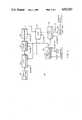
- FIG. 2is a block diagram of a voltage-controlled oscillator employing the invention
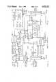
- FIG. 3is a more detailed block diagram of a compensating signal value calculator shown in FIG. 2;
- FIG. 4is a block diagram of an arithmetic logic unit shown in FIG. 2.
- FIG. 1is an illustration of a temperature-frequency transfer curve, depicting the frequency of the oscillator output signal as a function of ambient temperature.
- compensating signals offsetting the frequency changesare used to control the oscillator output signal.
- the value of the compensating signal corresponding to a particular ambient temperaturemay be determined by comparing the point of the transfer curve corresponding to the ambient temperature with the desired output signal frequency.
- the compensation signal valueis the inverse, that is, the negative, of this frequency difference.
- the purpose of the circuitryis to calculate the compensating signal value which will precisely compensate the oscillator output signal by characterizing the portion of transfer curve surrounding the ambient temperature. Rather than storing a value for every temperature, we partition the transfer curve corresponding to the operative temperature range into segments and store only one value for each segment.
- the stored valueis the compensating value corresponding to a temperature within each segment. In the preferred embodiment the stored values correspond to the temperature at the start of each segment.
- a function representing the parabolic curve that includes the stored values for the k-1, k and k+1 transfer curve segmentsis formulated.
- the compensating signal valueis equal to the value of the function at the ambient temperature.
- the transfer curveis partitioned into "n" segments, with n equaling 64 in the preferred embodiment.
- the segmentsneed not be of equal size, and, in fact, in the preferred embodiment the segments corresponding to steeper portions of the curve are smaller than the segments corresponding to portions of the curve that are not so steep.
- the segmentsare partitioned into "q" sub-segments, with q equaling 16 in the preferred embodiment.
- the ambient temperatureis characterized by the transfer curve segment and sub-segment associated with it. As described in more detail with reference to FIG. 2 below, the sub-segment values are used to measure the difference between the ambient temperature and the temperature at the start of a segment in which the ambient temperature falls. This difference, labeled "delta T", is substituted into the appropriate Taylor Series function to calculate the compensating signal value.
- the offset valueis equal to the signal value which compensates for the difference between the desired frequency and the frequency at the segment starting point on the transfer curve 1.
- the offset valuesare then stored in a look-up table.
- T Alocated in segment k
- the offset values x k-1 , x k and x k+1 associated with segments k-1, k and k+1, respectively,are retrieved from the look-up table.
- the calculator circuitryuses these values to compute the parabola that passes through the points that the values represent.
- the compensating signal valueis calculated by substituting the actual value of delta T into equation 2.
- the oscillator output signalis then compensated by applying to the oscillator as the control voltage a compensating signal corresponding to the calculated value.
- the frequency of its output signalshifts up or down. This frequency shift is unrelated to the ambient temperature. Thus the frequency shift, in effect, moves the entire temperature-frequency transfer curve up or down by some amount.
- the compensating signal calculatoris recalibrated every so often to determine the amount of the shift and the voltage required to offset it, that is, the aging offset value. This aging offset value is then included in the Taylor Series function and equation 2 becomes: ##EQU10## where x A is the aging offset value.
- FIG. 2depicts a compensating signal value calculator circuit 10.
- a temperature sensor 12produces a voltage related to the ambient temperature and provides it to an analog-to-digital (“A/D") converter 14.
- the A/D converter 14converts the voltage to a 10-bit digital symbol, or temperature word.
- the six most significant bits of the temperature worddesignate the transfer curve segment corresponding to the ambient temperature.
- the four least significant bits of the temperature worddesignate the sub-segment containing the temperature.
- the six most significant bits of the temperature word designate segment k and the four least significant bitsdesignate delta T.
- the A/D converter 14applies the 10-bit temperature word to both an address decoder 16 and an arithmetic logic unit ("ALU") 22.
- ALUarithmetic logic unit
- the address decoder 16formulates addresses for accessing locations associated with the ambient temperature in a memory 18.
- the memory 18contains the offset value look-up table.
- the addresses supplied by the address decoder 16access the locations containing the offset values for the k, k-1 and k+1 transfer curve segments.
- the offset values for the three segments x k-1 , x k , and x k+1are retrieved from the look-up table and applied to the ALU 22.
- the ALU 22then calculates the coefficients for the Taylor Series function representing the k th segment of the transfer curve in the manner described with reference to FIG. 1 above.
- the ALU 22next calculates the compensation signal value by substituting into the Taylor Series function the delta T value received from the A/D converter 14, that is, the four least significant bits of the temperature word.
- a digital-to-analog (“D/A") converter 24then converts the compensation signal value, which is a 10-bit digital symbol, to an analog signal.
- the analog signalis the control voltage applied to voltage-controlled oscillator 26 producing a stable frequency output signal on line 26A.
- Circuit control signals and clock information from an external sourceare supplied to the circuit through a serial interface 20.
- the system CPUdictates in which of four modes, namely, calibrate, program, normal, or test, the circuit operates.
- the serial interface 20communicates the operating mode to the remaining circuit elements using two MODE lines. The operation of the circuit 10 in each of the four modes will be described in more detail with reference to FIG. 3 below.
- the compensating signal value calculator circuit 10, exclusive of the memory 18,is designed for fabrication on a single integrated circuit chip.
- the serial interface 20allows external circuitry access to the circuit through clock and data lines. When the circuit is operating in the normal mode, that is, calculating compensation signal values based on ambient temperature readings, it is internally controlled based on system clock information provIded by the CPU.
- a state controller 26 and a sequencer state machine 28control the operation of the circuit when it is operating in the normal mode.
- the state controller 26is an 8-bit counter and the sequencer state machine 28 is a read only memory ("ROM").
- the counterclocked by the system clock, counts the states through which the sequencer state machine SSM 28 steps, addressing the ROM with each count
- the ROM 28in response to the changing count, applies various control signals to the remainder of the circuit 10 over SSM control lines 28A.
- the serial interface 20sets the MODE lines to the appropriate value, and forwards from the CPU a chip select, CS, signal which enables the address decoder 16.
- the calculator circuit 10is clocked by the system clock signal which is supplied by the system CPU on line 11.
- the serial interface 20may be used to slow the operation of the circuit 10, for example, during periods of relatively infrequent changes in ambient temperature, by asserting a slow clock signal on line 13A.
- the slow clock signalenables a clock controller 13 which, in effect, divides the master clock signal by some predetermined value. By slowing the clock, the circuit 10 requires less power to perform the calculation, and it is thus well suited to battery-powered operation.
- the A/D converter 14,which is enabled and strobed by the sequencer state machine 28, converts the temperature reading of the temperature sensor 12 to a corresponding 10-bit temperature word.
- the temperature wordis applied to a multiplexer 15 which normally forwards the six most significant bits to the address decoder 16 and the four least significant bits to the ALU 22.
- the address decoder 16formulates the memory address corresponding to the k th segment of the transfer curve.
- the sequencer state machine 28next sends control signals to the address decoder 16 over a REL ADDR line, one of the SSM control lines 28A, instructing the address decoder 16 to formulate the addresses corresponding to the k+1 and k-1 transfer curve segments.
- the address decoder 16then sends the addresses to the memory 18 over a MEMORY DATA line. It also sends chip select and memory read instructions, and clock information over a MEMORY CS line and a MEMORY CLK line, respectively. In response the memory 18 retrieves the stored offset values, x k , x k+1 and x k-1 , and sends them to a buffer 21.
- the buffer 21includes four 10-bit registers, three for storing the retrieved transfer curve offset values and a fourth for storing the aging offset value, x A , as discussed above with reference to FIG. 1.
- the aging offset value, x Ais stored in the memory 18 at a location corresponding to an address contained in an offset register 17.
- the address decoder 16retrieves from the offset register 17 the aging offset value address and applies it to the memory 18.
- the memory 18accesses the location and supplies the contents of it, the aging offset value, x A , to the buffer 21.
- the ALU 22acquires the contents of the buffer 21 and calculates the Taylor Series coefficients for the k th segment of the transfer curve. Using this function and the delta T value received from the A/D converter 14, the ALU 22 calculates the compensating signal value.
- the compensating signal value calculationcan be performed in one step using equation 2.
- the offset values in buffer 21are combined with the delta T value in accordance with equation 3 and the compensating signal value is calculated without explicitly determining the Taylor Series coefficients.
- the resulting compensating signal valuewhich is a 10-bit digital symbol, is stored in ALU register 22A.
- the ALU register 22Athen transmits the symbol, in parallel, to the D/A converter 24.
- the D/A converter 24converts the signal value from digital to analog and applies it to the oscillator 26 (FIG. 2).
- the circuit 10Before the circuit 10 can calculate compensating signal values, it must be calibrated and programmed. Calibration involves operating the circuit 10 at various temperatures and plotting the temperature-frequency transfer curve. Programming involves writing offset values to the memory 18 locations corresponding to known temperatures. Accordingly, the circuit 10 operates first in the calibrate mode and then in the program mode before it ever operates in normal mode.
- the circuit 10is calibrated and programmed at the factory under the control of a calibrating-programming CPU.
- the external CPUcommunicates with the circuit components through the serial interface 20 over DATA IN and DATA OUT lines.
- the CPU(not shown) instructs the serial interface 20 to operate the circuit 10 in calibrate mode, and the serial interface 20 communicates the appropriate mode information to the circuit components over the MODE lines.
- the circuit 10 operating in calibrate modeis placed in an oven and the ambient temperature is increased.
- the CPUthrough the serial interface 20, applies successive signal values to the D/A converter 24 until a value is found which precisely compensates the oscillator output signal.
- the CPUthen stores this value and the corresponding temperature word produced by the A/D converter 14 in response to the corresponding temperature signal from temperature sensor 12. This procedure is repeated for various temperatures until the temperature-frequency characteristics of the oscillator are determined.
- the CPUthen plots the temperature-frequency transfer curve.
- the CPUpartitions the curve into n segments and determines the offset value, x n , corresponding to the start of each segment.
- the circuit 10is then operated in program mode to write the offset values to the memory 18.
- the CPUIn program mode the CPU, through serial interface 20, loads the memory 18.
- the serial interface 20behaves as a transparent interface between the CPU and the address decoder 16.
- the CPUsupplies to the address decoder 16, over the DATA IN line, the temperature word and the associated offset values, x n , corresponding to the starting point of each of the n transfer curve segments.
- the address decoder 16uses the six most significant bits of a temperature word, addresses a location in the memory 18 and writes to it the associated offset value, x n .
- the memory location assigned to the aging offset valueis written with an offset value, x A , signifying the lack of aging effects.
- the locationmay have an all ZERO symbol written in.
- the calibrated aging offset values written to the locationwill contain a sign-bit to indicate positive or negative offset.
- the locationis first written with the symbol 0111111111, which is the mid-point of all possible offset values. Therafter, the calibrated aging offset values written to the location will be either (numerically) higher or lower to indicate positive or negative offset.
- the circuitAfter the circuit has been operating for some time it is re-calibrated at a known temperature, for example, room temperature, to determine if the output signal frequency has shifted due to the aging of the crystal. If there is such a frequency shift, successive compensating signal values are applied to the D/A converter 24 until the oscillator output signal is precisely compensated.
- the compensating signal value attributable to agingthat is, the difference between the calculated offset value and the calibrated offset value, is then written to the memory location reserved for the aging offset value, x A . Thereafter, the circuit is re-calibrated at room temperature as often as necessary. The need for re-calibration is determined by the particular aging characteristic of the crystal and, also, by the frequency-precision requirements of the system in which the oscillator is operating.
- re-calibrationis performed by comparing the frequency of the output signal with a known, highly precise clock signal.
- the CPUperforms the comparison, integrates and averages the signal difference over time, and combines the results with the stored x A value to calculate a new x A value.
- This new x A valueis then stored in the memory 18.
- Re-calibrationis thus performed using integrated circuit components and the system CPU. Accordingly, re-calibration can be performed automatically and relatively frequently, for example, each time the circuitry is powered-up.
- the calculator circuit 10is configured for easy testing. Several components have "scan" architecture enabling them to operate their internal registers as shift registers, serially shifting out the register contents.
- the serial interface 20receives from the system CPU an instruction to perform testing, it asserts a testing mode signal over the MODE lines. Operating in testing mode, various scan architecture components are tested by scanning, and various other components are tested by checking the results of predetermined operations, for example, analog-to-digital conversion of a known value.
- the serial interface 20controls the testing of the scan-type components using scan control lines, namely SCAN IN, SCAN SEL, and SCAN CLK.
- the system CPUsends testing instructions to the serial interface 20 over a DATA IN line.
- the serial interface 20selects the components for testing, by asserting the appropriate chip select lines, and provides data and clock information to them, as necessary, over the SCAN control lines.
- the componentssend test information back to the serial interface 20 over a SCAN OUT line, and the serial interface 20 transmits this information to the system CPU over the DATA OUT line.
- the CPUanalyzes the data to determine if the components are correctly operating.
- the circuit 10may also be fully digitally tested by by-passing the A/D converter 14 and the D/A converter 28.
- the serial interface 20transmits a digital symbol directly to the multiplexer 15 and operates the decoder 16 and the ALU 22 to complete the compensating signal calculation.
- the serial interface 20then retrieves the resulting compensating signal value from the ALU register 22A before the D/A converter 28 converts it to an analog signal.
- FIG. 4depicts the ALU 22 in block diagram form. It is hardware efficient, containing a minimal number of gates.
- the ALU 22includes sixteen full adders 22B connected such that each adder 22B corresponds to one of sixteen data bits.
- Each adder 22Balso includes a 2:1 multiplexer for multiplexing the data bit to the adder 22B in a true or inverted form, allowing the adder 22B to perform addition or subtraction, respectively.
- the ALU 22retrieves the four offset values stored in buffer 21 (FIG. 3) and manipulates them in the manner described above with reference to FIG. 1, producing the offset, linear and second-order coefficients of a second-order Taylor Series function.
- the coefficientsare stored in ALU register 22A.
- the four adders 22B corresponding to bits 0-3also function is full multipliers with a summing capability implementing a bit serial architecture.
- the adder-multipliers 22Bmultiply the contents of ALU register 22A by the four-bit delta T value, that is, the four least significant bits of the 10-bit temperature word received from A/D converter 14, by serially shifting in the coefficients stored in the 16-bit ALU register 22A. The products are summed and shifted to achieve the proper placement of the binary digits in the ALU register 22A, forming a 10-bit compensating signal value.
- the ALU 22may be configured to calculate the compensating signal value using equation 3.
- the temperature and aging offset valuesare retrieved from the buffer 21 (FIG. 3) and they are combined with the delta T value received from the A/D converter 14 (FIG. 3) to calculate the various terms of equation 3, without explicitly calculating the linear and second order coefficients.
- the termsare then summed and shifted, as set forth above, to achieve the proper placement of the binary digits in the ALU register 22A.
- the compensating signal value calculatorgenerates a compensating signal which accurately compensates for frequency variations in the output signal of a voltage-controlled oscillator.
- the circuitgenerates the compensating signal by calculating coefficients for a second-order Taylor Series function describing the portion of the oscillator temperature-frequency transfer curve corresponding to the ambient temperature. Using this function and the ambient temperature, the circuit then calculates the compensating signal value required to maintain the output signal precisely at the desired frequency.
- the circuitnot only compensates the output signal for frequency variations due to changes in ambient temperature, it also compensates for variations due to the aging of the oscillator crystal.
- An aging offset valueis included in the second-order Taylor Series to offset the inevitable shift, up or down, of the transfer curve due to the aging of the crystal.
- the circuitprecisely compensates the oscillator output signal for both temperature and age.
- the compensating signal value calculation circuitis designed for ease of manufacturability and low power consumption.
- the circuitis configured to fit on a single integrated circuit chip with an external, programmable memory. Due to its low power consumption, the circuit may be used in connection with battery-powered circuitry, for example, as part of a cellular telephone.
Landscapes
- Oscillators With Electromechanical Resonators (AREA)
- Stabilization Of Oscillater, Synchronisation, Frequency Synthesizers (AREA)
Abstract
Description
Claims (13)
Priority Applications (8)
| Application Number | Priority Date | Filing Date | Title |
|---|---|---|---|
| US07/361,551US4922212A (en) | 1989-06-05 | 1989-06-05 | Oscillator temperature compensating circuit using stored and calculated values |
| CA002018264ACA2018264C (en) | 1989-06-05 | 1990-06-05 | Oscillator temperature compensating circuit using stored and calculated values |
| AU57378/90AAU5737890A (en) | 1989-06-05 | 1990-06-05 | Oscillator temperature compensating circuit using stored and calculated values |
| EP90908447AEP0428672A1 (en) | 1989-06-05 | 1990-06-05 | Oscillator temperature compensating circuit using stored and calculated values |
| FI910535AFI910535A7 (en) | 1989-06-05 | 1990-06-05 | Oscillator temperature compensation circuit using stored and calculated values |
| JP2507883AJPH04503447A (en) | 1989-06-05 | 1990-06-05 | Oscillator temperature compensation circuit using stored calculated values |
| PCT/CA1990/000183WO1990015483A1 (en) | 1989-06-05 | 1990-06-05 | Oscillator temperature compensating circuit using stored and calculated values |
| NO91910419ANO910419L (en) | 1989-06-05 | 1991-02-04 | TEMPERATURE CORRECTION CIRCUITS FOR OSCILLATOR, BASED ON USE OF STORED AND CALCULATED VALUES. |
Applications Claiming Priority (1)
| Application Number | Priority Date | Filing Date | Title |
|---|---|---|---|
| US07/361,551US4922212A (en) | 1989-06-05 | 1989-06-05 | Oscillator temperature compensating circuit using stored and calculated values |
Publications (1)
| Publication Number | Publication Date |
|---|---|
| US4922212Atrue US4922212A (en) | 1990-05-01 |
Family
ID=23422498
Family Applications (1)
| Application Number | Title | Priority Date | Filing Date |
|---|---|---|---|
| US07/361,551Expired - LifetimeUS4922212A (en) | 1989-06-05 | 1989-06-05 | Oscillator temperature compensating circuit using stored and calculated values |
Country Status (6)
| Country | Link |
|---|---|
| US (1) | US4922212A (en) |
| EP (1) | EP0428672A1 (en) |
| JP (1) | JPH04503447A (en) |
| AU (1) | AU5737890A (en) |
| CA (1) | CA2018264C (en) |
| WO (1) | WO1990015483A1 (en) |
Cited By (44)
| Publication number | Priority date | Publication date | Assignee | Title |
|---|---|---|---|---|
| US5170136A (en)* | 1990-09-14 | 1992-12-08 | Nihon Dempa Kogyo Co., Ltd. | Digital temperature compensation oscillator |
| US5349676A (en)* | 1991-02-11 | 1994-09-20 | General Electric Company | Data acquisition systems with programmable bit-serial digital signal processors |
| US5392005A (en)* | 1993-09-30 | 1995-02-21 | At&T Corp. | Field calibration of a digitally compensated crystal oscillator over a temperature range |
| WO1996024097A1 (en)* | 1995-01-31 | 1996-08-08 | Motorola Inc. | Logarithm/inverse-logarithm converter and method of using same |
| WO1996024094A1 (en)* | 1995-01-31 | 1996-08-08 | Motorola Inc. | Logarithm/inverse-logarithm converter utilizing second-order term and method of using same |
| WO1996024096A1 (en)* | 1995-01-31 | 1996-08-08 | Motorola Inc. | Logarithm/inverse-logarithm converter utilizing a truncated taylor series and method of use thereof |
| WO1996024986A1 (en)* | 1995-02-10 | 1996-08-15 | Matsushita Communication Industrial Corporation Of America | Crystal oscillator with automatic compensation for aging and temperature |
| WO1996026478A1 (en)* | 1995-02-22 | 1996-08-29 | Motorola Inc. | Logarithm/inverse-logarithm converter utilizing linear interpolation and method of using same |
| US5585750A (en)* | 1994-06-07 | 1996-12-17 | Hitachi, Ltd. | Logic LSI |
| EP0744836A3 (en)* | 1995-05-25 | 1998-03-25 | Kabushiki Kaisha Meidensha | Temperature compensated crystal oscillator |
| US5757244A (en)* | 1996-02-23 | 1998-05-26 | Kyocera Corporation | Digital control type oscillation circuit of portable telephone, crystal resonator oscillation frequency calculating method, and outputfrequency correcting method |
| US5771180A (en)* | 1994-09-30 | 1998-06-23 | Apple Computer, Inc. | Real time clock and method for providing same |
| US5892408A (en)* | 1997-01-31 | 1999-04-06 | Binder; Yehuda | Method and system for calibrating a crystal oscillator |
| US5897605A (en)* | 1996-03-15 | 1999-04-27 | Sirf Technology, Inc. | Spread spectrum receiver with fast signal reacquisition |
| US5901171A (en)* | 1996-03-15 | 1999-05-04 | Sirf Technology, Inc. | Triple multiplexing spread spectrum receiver |
| US6018704A (en)* | 1996-04-25 | 2000-01-25 | Sirf Tech Inc | GPS receiver |
| US6041280A (en)* | 1996-03-15 | 2000-03-21 | Sirf Technology, Inc. | GPS car navigation system |
| US6047017A (en)* | 1996-04-25 | 2000-04-04 | Cahn; Charles R. | Spread spectrum receiver with multi-path cancellation |
| US6125325A (en)* | 1996-04-25 | 2000-09-26 | Sirf Technology, Inc. | GPS receiver with cross-track hold |
| US6198765B1 (en) | 1996-04-25 | 2001-03-06 | Sirf Technologies, Inc. | Spread spectrum receiver with multi-path correction |
| US20010002203A1 (en)* | 1996-04-25 | 2001-05-31 | Cahn Charles R. | Spread spectrum receiver with multi-path correction |
| US6249542B1 (en) | 1997-03-28 | 2001-06-19 | Sirf Technology, Inc. | Multipath processing for GPS receivers |
| US6282231B1 (en) | 1999-12-14 | 2001-08-28 | Sirf Technology, Inc. | Strong signal cancellation to enhance processing of weak spread spectrum signal |
| US6393046B1 (en) | 1996-04-25 | 2002-05-21 | Sirf Technology, Inc. | Spread spectrum receiver with multi-bit correlator |
| US6483371B1 (en) | 2000-10-02 | 2002-11-19 | Northrop Grumman Corporation | Universal temperature compensation application specific integrated circuit |
| US6559731B2 (en) | 2000-03-17 | 2003-05-06 | Telefonaktiebolaget Lm Ericsson (Publ) | VCXO temperature compensation circuit |
| US20040038659A1 (en)* | 2002-08-14 | 2004-02-26 | Nec Corporation | Automatic frequency control system, operation control method thereof and mobile communication device using the same |
| US6853259B2 (en)* | 2001-08-15 | 2005-02-08 | Gallitzin Allegheny Llc | Ring oscillator dynamic adjustments for auto calibration |
| US20050146244A1 (en)* | 2004-01-07 | 2005-07-07 | Ruvinda Gunawardana | Frequency characterization of quartz crystals |
| US20060284733A1 (en)* | 2005-06-20 | 2006-12-21 | Mccall James A | Initiation of differential link retraining upon temperature excursion |
| US20070092035A1 (en)* | 2005-10-26 | 2007-04-26 | Lg Electronics Inc. | Method of compensating for the frequency error of system clock in mobile communication terminal with digitally controlled crystal oscillator and mobile communication terminal thereof |
| US20080061899A1 (en)* | 2006-09-12 | 2008-03-13 | Stolpman James L | Apparatus and method for temperature compensation of crystal oscillators |
| US7371005B1 (en)* | 2006-11-16 | 2008-05-13 | Intersil Americas Inc. | Automatic circuit and method for temperature compensation of oscillator frequency variation over temperature for a real time clock chip |
| US20090160569A1 (en)* | 2007-12-20 | 2009-06-25 | Pentad Design Corporation | Systems and methods for compensating for variations of the output of a real-time clock |
| WO2014018401A1 (en)* | 2012-07-27 | 2014-01-30 | Qualcomm Incorporated | Methods for addressing aging of xo crystals |
| US9537448B2 (en)* | 2015-02-04 | 2017-01-03 | Seiko Epson Corporation | Oscillator, electronic apparatus, and moving object |
| CN106953597A (en)* | 2016-01-06 | 2017-07-14 | 精工爱普生株式会社 | Circuit devices, oscillators, electronic equipment, and moving objects |
| EP3226419A1 (en) | 2016-03-31 | 2017-10-04 | u-blox AG | Adaptive temperature compensation for an oscillator |
| US20180212609A1 (en)* | 2017-01-24 | 2018-07-26 | Seiko Epson Corporation | Circuit device, oscillator, physical quantity measurement device, electronic apparatus, and vehicle |
| EP3355626A1 (en)* | 2017-01-30 | 2018-08-01 | Commsolid GmbH | Method and apparatus for digital quartz temperature and drift compensation for a sleep timer of a nb-iot device |
| US20180241344A1 (en)* | 2017-02-23 | 2018-08-23 | Seiko Epson Corporation | Circuit device, oscillator, electronic apparatus, vehicle, and manufacturing method for circuit device |
| US10985928B2 (en) | 2017-01-24 | 2021-04-20 | Seiko Epson Corporation | Circuit device, oscillation device, physical quantity measuring device, electronic apparatus, and vehicle |
| WO2021116911A1 (en)* | 2019-12-10 | 2021-06-17 | Wiliot, LTD. | Single layer lc oscillator |
| CN114113974A (en)* | 2021-11-01 | 2022-03-01 | 海光信息技术股份有限公司 | Chip system level test method and device |
Families Citing this family (6)
| Publication number | Priority date | Publication date | Assignee | Title |
|---|---|---|---|---|
| ES2040622B1 (en)* | 1991-09-30 | 1995-12-16 | Tiempo Frecuencia Y Electronic | SELF-COMPENSATED OSCILLATOR IN TEMPERATURE. |
| DE4209843A1 (en)* | 1992-03-26 | 1993-11-18 | Telefunken Microelectron | Temp. compensated oscillator circuit - stores tuning element setting signal and corresponding temp. signal during calibration phase for subsequent provision of correction signal |
| NL9201372A (en)* | 1992-07-29 | 1994-02-16 | Sierra Semiconductor Bv | Temperature compensated oscillator circuit. |
| JP6415285B2 (en)* | 2014-12-08 | 2018-10-31 | セイコーNpc株式会社 | Temperature voltage sensor |
| US10886929B2 (en) | 2018-05-31 | 2021-01-05 | Wiliot, LTD. | Oscillator calibration from over-the-air signals for low power frequency/time references wireless radios |
| US10700718B2 (en) | 2018-07-19 | 2020-06-30 | Wiliot, LTD. | Frequency detection for over-the-air calibration of oscillators |
Citations (8)
| Publication number | Priority date | Publication date | Assignee | Title |
|---|---|---|---|---|
| US3713033A (en)* | 1971-09-01 | 1973-01-23 | Collins Radio Co | Digitally temperature compensated oscillator |
| US3719838A (en)* | 1971-08-02 | 1973-03-06 | Bulova Watch Co Inc | Temperature compensating digital system for electromechanical resonators |
| US3821665A (en)* | 1973-06-11 | 1974-06-28 | Motorola Inc | Temperature compensated crystal oscillator |
| US4160183A (en)* | 1978-05-26 | 1979-07-03 | Hewlett-Packard Company | Oscillator having a quartz resonator cut to compensate for static and dynamic thermal transients |
| US4560959A (en)* | 1982-05-18 | 1985-12-24 | Standard Telephones And Cables Public Limited Company | Temperature controlled crystal oscillator arrangement |
| US4611181A (en)* | 1984-09-10 | 1986-09-09 | Nec Corporation | Temperature compensated oscillator with reduced noise |
| US4633422A (en)* | 1983-07-26 | 1986-12-30 | Cincinnati Electronics Corporation | Apparatus for and method of compensating for variations due to aging |
| US4746879A (en)* | 1986-08-28 | 1988-05-24 | Ma John Y | Digitally temperature compensated voltage-controlled oscillator |
Family Cites Families (1)
| Publication number | Priority date | Publication date | Assignee | Title |
|---|---|---|---|---|
| SU1136299A1 (en)* | 1982-04-29 | 1985-01-23 | Войсковая Часть 25871 | Process for temperature compensation of crystal oscillator |
- 1989
- 1989-06-05USUS07/361,551patent/US4922212A/ennot_activeExpired - Lifetime
- 1990
- 1990-06-05JPJP2507883Apatent/JPH04503447A/enactivePending
- 1990-06-05WOPCT/CA1990/000183patent/WO1990015483A1/ennot_activeApplication Discontinuation
- 1990-06-05CACA002018264Apatent/CA2018264C/ennot_activeExpired - Lifetime
- 1990-06-05AUAU57378/90Apatent/AU5737890A/ennot_activeAbandoned
- 1990-06-05EPEP90908447Apatent/EP0428672A1/ennot_activeWithdrawn
Patent Citations (8)
| Publication number | Priority date | Publication date | Assignee | Title |
|---|---|---|---|---|
| US3719838A (en)* | 1971-08-02 | 1973-03-06 | Bulova Watch Co Inc | Temperature compensating digital system for electromechanical resonators |
| US3713033A (en)* | 1971-09-01 | 1973-01-23 | Collins Radio Co | Digitally temperature compensated oscillator |
| US3821665A (en)* | 1973-06-11 | 1974-06-28 | Motorola Inc | Temperature compensated crystal oscillator |
| US4160183A (en)* | 1978-05-26 | 1979-07-03 | Hewlett-Packard Company | Oscillator having a quartz resonator cut to compensate for static and dynamic thermal transients |
| US4560959A (en)* | 1982-05-18 | 1985-12-24 | Standard Telephones And Cables Public Limited Company | Temperature controlled crystal oscillator arrangement |
| US4633422A (en)* | 1983-07-26 | 1986-12-30 | Cincinnati Electronics Corporation | Apparatus for and method of compensating for variations due to aging |
| US4611181A (en)* | 1984-09-10 | 1986-09-09 | Nec Corporation | Temperature compensated oscillator with reduced noise |
| US4746879A (en)* | 1986-08-28 | 1988-05-24 | Ma John Y | Digitally temperature compensated voltage-controlled oscillator |
Non-Patent Citations (2)
| Title |
|---|
| T. Miyayama et al., "A New Digitally Temperature Compensated Crystal Oscillator for a Mobile Telephone System", pp. 327-333, 42nd Annual Frequency Control Symposium--1988, CH2588-2/88/0000--327 IEEE. |
| T. Miyayama et al., A New Digitally Temperature Compensated Crystal Oscillator for a Mobile Telephone System , pp. 327 333, 42nd Annual Frequency Control Symposium 1988, CH2588 2/88/0000 327 IEEE.* |
Cited By (87)
| Publication number | Priority date | Publication date | Assignee | Title |
|---|---|---|---|---|
| US5170136A (en)* | 1990-09-14 | 1992-12-08 | Nihon Dempa Kogyo Co., Ltd. | Digital temperature compensation oscillator |
| US5349676A (en)* | 1991-02-11 | 1994-09-20 | General Electric Company | Data acquisition systems with programmable bit-serial digital signal processors |
| US5448747A (en)* | 1991-02-11 | 1995-09-05 | General Electric Company | Analog voltage metering system with programmable bit-serial digital signal processors |
| US5392005A (en)* | 1993-09-30 | 1995-02-21 | At&T Corp. | Field calibration of a digitally compensated crystal oscillator over a temperature range |
| US5585750A (en)* | 1994-06-07 | 1996-12-17 | Hitachi, Ltd. | Logic LSI |
| US5771180A (en)* | 1994-09-30 | 1998-06-23 | Apple Computer, Inc. | Real time clock and method for providing same |
| US5642305A (en)* | 1995-01-31 | 1997-06-24 | Motorola, Inc. | Logarithm/inverse-logarithm converter and method of using same |
| WO1996024097A1 (en)* | 1995-01-31 | 1996-08-08 | Motorola Inc. | Logarithm/inverse-logarithm converter and method of using same |
| WO1996024094A1 (en)* | 1995-01-31 | 1996-08-08 | Motorola Inc. | Logarithm/inverse-logarithm converter utilizing second-order term and method of using same |
| WO1996024096A1 (en)* | 1995-01-31 | 1996-08-08 | Motorola Inc. | Logarithm/inverse-logarithm converter utilizing a truncated taylor series and method of use thereof |
| US5703801A (en)* | 1995-01-31 | 1997-12-30 | Motorola, Inc. | Logarithm/inverse-logarithm converter utilizing second-order term and method of using same |
| US5604691A (en)* | 1995-01-31 | 1997-02-18 | Motorola, Inc. | Logarithm/inverse-logarithm converter utilizing a truncated Taylor series and method of use thereof |
| US5875388A (en)* | 1995-02-10 | 1999-02-23 | Matsushita Communication Industrial Corporation Of America | Crystal oscillator with automatic compensation for aging and temperature |
| WO1996024986A1 (en)* | 1995-02-10 | 1996-08-15 | Matsushita Communication Industrial Corporation Of America | Crystal oscillator with automatic compensation for aging and temperature |
| US5659884A (en)* | 1995-02-10 | 1997-08-19 | Matsushita Communication Industrial Corp. Of America | System with automatic compensation for aging and temperature of a crystal oscillator |
| US5600581A (en)* | 1995-02-22 | 1997-02-04 | Motorola, Inc. | Logarithm/inverse-logarithm converter utilizing linear interpolation and method of using same |
| WO1996026478A1 (en)* | 1995-02-22 | 1996-08-29 | Motorola Inc. | Logarithm/inverse-logarithm converter utilizing linear interpolation and method of using same |
| EP0744836A3 (en)* | 1995-05-25 | 1998-03-25 | Kabushiki Kaisha Meidensha | Temperature compensated crystal oscillator |
| US5757244A (en)* | 1996-02-23 | 1998-05-26 | Kyocera Corporation | Digital control type oscillation circuit of portable telephone, crystal resonator oscillation frequency calculating method, and outputfrequency correcting method |
| US6522682B1 (en) | 1996-03-15 | 2003-02-18 | Sirf Technology, Inc. | Triple multiplexing spread spectrum receiver |
| US5897605A (en)* | 1996-03-15 | 1999-04-27 | Sirf Technology, Inc. | Spread spectrum receiver with fast signal reacquisition |
| US5901171A (en)* | 1996-03-15 | 1999-05-04 | Sirf Technology, Inc. | Triple multiplexing spread spectrum receiver |
| US6788735B2 (en) | 1996-03-15 | 2004-09-07 | Sirf Technology, Inc. | Triple multiplexing spread spectrum receiver |
| US6041280A (en)* | 1996-03-15 | 2000-03-21 | Sirf Technology, Inc. | GPS car navigation system |
| US6292749B2 (en) | 1996-03-15 | 2001-09-18 | Sirf Technology, Inc. | GPS receiver with cross-track hold |
| US7295633B2 (en) | 1996-03-15 | 2007-11-13 | Sirf Technology, Inc. | Triple multiplexing spread spectrum receiver |
| US6125325A (en)* | 1996-04-25 | 2000-09-26 | Sirf Technology, Inc. | GPS receiver with cross-track hold |
| US6236937B1 (en) | 1996-04-25 | 2001-05-22 | Sirf Technology, Inc. | GPS receiver with cross-track hold |
| US20010002203A1 (en)* | 1996-04-25 | 2001-05-31 | Cahn Charles R. | Spread spectrum receiver with multi-path correction |
| US6198765B1 (en) | 1996-04-25 | 2001-03-06 | Sirf Technologies, Inc. | Spread spectrum receiver with multi-path correction |
| US6917644B2 (en) | 1996-04-25 | 2005-07-12 | Sirf Technology, Inc. | Spread spectrum receiver with multi-path correction |
| US6047017A (en)* | 1996-04-25 | 2000-04-04 | Cahn; Charles R. | Spread spectrum receiver with multi-path cancellation |
| US6393046B1 (en) | 1996-04-25 | 2002-05-21 | Sirf Technology, Inc. | Spread spectrum receiver with multi-bit correlator |
| US6400753B1 (en) | 1996-04-25 | 2002-06-04 | Sirf Technology, Inc. | Pseudo-noise correlator for a GPS spread spectrum receiver |
| US6421609B2 (en) | 1996-04-25 | 2002-07-16 | Sirf Technology, Inc. | GPS receiver with cross-track hold |
| US6018704A (en)* | 1996-04-25 | 2000-01-25 | Sirf Tech Inc | GPS receiver |
| US6574558B2 (en) | 1996-04-25 | 2003-06-03 | Sirf Technology, Inc. | GPS receiver with cross-track hold |
| US6633814B2 (en) | 1996-04-25 | 2003-10-14 | Sirf Technology, Inc. | GPS system for navigating a vehicle |
| US5892408A (en)* | 1997-01-31 | 1999-04-06 | Binder; Yehuda | Method and system for calibrating a crystal oscillator |
| US6760364B2 (en)* | 1997-03-28 | 2004-07-06 | Sirf Technology, Inc. | Multipath processing for GPS receivers |
| US20040184516A1 (en)* | 1997-03-28 | 2004-09-23 | Sanjai Kohli | Multipath processing for GPS receivers |
| US20030165186A1 (en)* | 1997-03-28 | 2003-09-04 | Sanjai Kohli | Multipath processing for GPS receivers |
| US7301992B2 (en) | 1997-03-28 | 2007-11-27 | Sirf Technology, Inc. | Multipath processing for GPS receivers |
| US6249542B1 (en) | 1997-03-28 | 2001-06-19 | Sirf Technology, Inc. | Multipath processing for GPS receivers |
| US6466612B2 (en) | 1997-03-28 | 2002-10-15 | Sirf Technology, Inc. | Multipath processing for GPS receivers |
| US6282231B1 (en) | 1999-12-14 | 2001-08-28 | Sirf Technology, Inc. | Strong signal cancellation to enhance processing of weak spread spectrum signal |
| US20050032513A1 (en)* | 1999-12-14 | 2005-02-10 | Norman Charles P. | Strong signal cancellation to enhance processing of weak spread spectrum signal |
| US7116704B2 (en) | 1999-12-14 | 2006-10-03 | Sirf Technology, Inc. | Strong signal cancellation to enhance processing of weak spread spectrum signal |
| US6559731B2 (en) | 2000-03-17 | 2003-05-06 | Telefonaktiebolaget Lm Ericsson (Publ) | VCXO temperature compensation circuit |
| US6483371B1 (en) | 2000-10-02 | 2002-11-19 | Northrop Grumman Corporation | Universal temperature compensation application specific integrated circuit |
| US6853259B2 (en)* | 2001-08-15 | 2005-02-08 | Gallitzin Allegheny Llc | Ring oscillator dynamic adjustments for auto calibration |
| US20050125181A1 (en)* | 2001-08-15 | 2005-06-09 | Norman Robert D. | Ring oscillator dynamic adjustments for auto calibration |
| US7068557B2 (en) | 2001-08-15 | 2006-06-27 | Robert D Norman | Ring oscillator dynamic adjustments for auto calibration |
| US20060197696A1 (en)* | 2001-08-15 | 2006-09-07 | Norman Robert D | Ring oscillator dynamic adjustments for auto calibration |
| US7209401B2 (en) | 2001-08-15 | 2007-04-24 | Robert D Norman | Ring oscillator dynamic adjustments for auto calibration |
| US20040038659A1 (en)* | 2002-08-14 | 2004-02-26 | Nec Corporation | Automatic frequency control system, operation control method thereof and mobile communication device using the same |
| US20050146244A1 (en)* | 2004-01-07 | 2005-07-07 | Ruvinda Gunawardana | Frequency characterization of quartz crystals |
| US7113051B2 (en) | 2004-01-07 | 2006-09-26 | Schlumberger Technology Corporation | Frequency characterization of quartz crystals |
| US7246022B2 (en)* | 2005-06-20 | 2007-07-17 | Intel Corporation | Initiation of differential link retraining upon temperature excursion |
| US20060284733A1 (en)* | 2005-06-20 | 2006-12-21 | Mccall James A | Initiation of differential link retraining upon temperature excursion |
| US20070092035A1 (en)* | 2005-10-26 | 2007-04-26 | Lg Electronics Inc. | Method of compensating for the frequency error of system clock in mobile communication terminal with digitally controlled crystal oscillator and mobile communication terminal thereof |
| US20080061899A1 (en)* | 2006-09-12 | 2008-03-13 | Stolpman James L | Apparatus and method for temperature compensation of crystal oscillators |
| US7649426B2 (en) | 2006-09-12 | 2010-01-19 | Cts Corporation | Apparatus and method for temperature compensation of crystal oscillators |
| US7371005B1 (en)* | 2006-11-16 | 2008-05-13 | Intersil Americas Inc. | Automatic circuit and method for temperature compensation of oscillator frequency variation over temperature for a real time clock chip |
| US20080117722A1 (en)* | 2006-11-16 | 2008-05-22 | Ahuja Bhupendra K | Automatic circuit and method for temperature compensation of oscillator frequency variation over temperature for a real time clock chip |
| USRE43236E1 (en) | 2006-11-16 | 2012-03-13 | Intersil Americas Inc. | Automatic circuit and method for temperature compensation of oscillator frequency variation over temperature for a real time clock chip |
| US7791418B2 (en) | 2007-12-20 | 2010-09-07 | Pentad Design, Llc | Systems and methods for compensating for variations of the output of a real-time clock |
| US20090160569A1 (en)* | 2007-12-20 | 2009-06-25 | Pentad Design Corporation | Systems and methods for compensating for variations of the output of a real-time clock |
| WO2014018401A1 (en)* | 2012-07-27 | 2014-01-30 | Qualcomm Incorporated | Methods for addressing aging of xo crystals |
| US8994466B2 (en) | 2012-07-27 | 2015-03-31 | Qualcomm Incorporated | Methods for addressing aging of XO crystals |
| US9537448B2 (en)* | 2015-02-04 | 2017-01-03 | Seiko Epson Corporation | Oscillator, electronic apparatus, and moving object |
| CN106953597A (en)* | 2016-01-06 | 2017-07-14 | 精工爱普生株式会社 | Circuit devices, oscillators, electronic equipment, and moving objects |
| US10651854B2 (en) | 2016-03-31 | 2020-05-12 | U-Blox Ag | Adaptive temperature compensation |
| EP3226419A1 (en) | 2016-03-31 | 2017-10-04 | u-blox AG | Adaptive temperature compensation for an oscillator |
| US10742221B2 (en)* | 2017-01-24 | 2020-08-11 | Seiko Epson Corporation | Circuit device, oscillator, physical quantity measurement device, electronic apparatus, and vehicle |
| US20180212609A1 (en)* | 2017-01-24 | 2018-07-26 | Seiko Epson Corporation | Circuit device, oscillator, physical quantity measurement device, electronic apparatus, and vehicle |
| US10985928B2 (en) | 2017-01-24 | 2021-04-20 | Seiko Epson Corporation | Circuit device, oscillation device, physical quantity measuring device, electronic apparatus, and vehicle |
| EP3355626A1 (en)* | 2017-01-30 | 2018-08-01 | Commsolid GmbH | Method and apparatus for digital quartz temperature and drift compensation for a sleep timer of a nb-iot device |
| US20180241344A1 (en)* | 2017-02-23 | 2018-08-23 | Seiko Epson Corporation | Circuit device, oscillator, electronic apparatus, vehicle, and manufacturing method for circuit device |
| CN108512546A (en)* | 2017-02-23 | 2018-09-07 | 精工爱普生株式会社 | The manufacturing method of circuit device, oscillator, electronic equipment, moving body and circuit device |
| US10461694B2 (en)* | 2017-02-23 | 2019-10-29 | Seiko Epson Corporation | Circuit device, oscillator, electronic apparatus, vehicle, and manufacturing method for circuit device |
| CN108512546B (en)* | 2017-02-23 | 2023-08-25 | 精工爱普生株式会社 | Circuit device, oscillator, electronic apparatus, moving object, and method for manufacturing circuit device |
| WO2021116911A1 (en)* | 2019-12-10 | 2021-06-17 | Wiliot, LTD. | Single layer lc oscillator |
| US11609128B2 (en)* | 2019-12-10 | 2023-03-21 | Wiliot, LTD. | Single layer LC oscillator |
| US12098962B2 (en) | 2019-12-10 | 2024-09-24 | Wiliot, LTD. | Single layer LC oscillator |
| CN114113974A (en)* | 2021-11-01 | 2022-03-01 | 海光信息技术股份有限公司 | Chip system level test method and device |
| CN114113974B (en)* | 2021-11-01 | 2023-10-27 | 海光信息技术股份有限公司 | Chip system level test method and device |
Also Published As
| Publication number | Publication date |
|---|---|
| JPH04503447A (en) | 1992-06-18 |
| EP0428672A1 (en) | 1991-05-29 |
| AU5737890A (en) | 1991-01-07 |
| WO1990015483A1 (en) | 1990-12-13 |
| CA2018264C (en) | 1996-03-12 |
| CA2018264A1 (en) | 1990-12-05 |
Similar Documents
| Publication | Publication Date | Title |
|---|---|---|
| US4922212A (en) | Oscillator temperature compensating circuit using stored and calculated values | |
| US5892408A (en) | Method and system for calibrating a crystal oscillator | |
| US4633422A (en) | Apparatus for and method of compensating for variations due to aging | |
| US4513259A (en) | Closed loop temperature compensated frequency reference | |
| CN103809658B (en) | Semiconductor device and clock correction method | |
| US6249155B1 (en) | Frequency correction circuit for a periodic source such as a crystal oscillator | |
| US5657237A (en) | Instrument and method for the digital electronic measurement of periodic electrical quantities | |
| JPS6123895B2 (en) | ||
| KR100235388B1 (en) | Energy measurement machine register device | |
| JPH03253108A (en) | Direct digital synthesizer and signal generation | |
| KR960003992B1 (en) | Variable delay circuit | |
| EP0536504B1 (en) | Calibration of a system comprising a reconfigurable sequence of stages | |
| US4217651A (en) | Electrical measurements | |
| US5004987A (en) | Temperature compensated crystal resonator found in a dual-mode oscillator | |
| CN101488752B (en) | Temperature frequency correction device | |
| GB2112527A (en) | Temperature measuring system | |
| JP4454126B2 (en) | Temperature compensation oscillator adjustment method | |
| KR940001682B1 (en) | Timing signal generator | |
| CN101388646B (en) | Successive approximation temperature and frequency correcting method and device | |
| CN102025368A (en) | Temperature sensing oscillator and production method thereof as well as temperature frequency correction system | |
| CN101488751B (en) | Measurement system and method for temperature frequency correcting apparatus | |
| JPH1172538A (en) | Ic testing device, measurement method and storage medium for ic testing device | |
| CN201515347U (en) | Temperature frequency correcting device | |
| US6728651B1 (en) | Methods and apparatuses for digitally tuning a phased-lock loop circuit | |
| CN201436786U (en) | Testing system of temperature frequency correction device |
Legal Events
| Date | Code | Title | Description |
|---|---|---|---|
| STCF | Information on status: patent grant | Free format text:PATENTED CASE | |
| AS | Assignment | Owner name:NOVATEL COMMUNICATIONS, LTD., CANADA Free format text:ASSIGNMENT OF ASSIGNORS INTEREST.;ASSIGNOR:PAYNTER, GORDON;REEL/FRAME:005287/0821 Effective date:19900312 Owner name:NOVATEL COMMUNICATIONS, LTD., CANADA Free format text:ASSIGNMENT OF ASSIGNORS INTEREST.;ASSIGNOR:KRISHNASASTRY, REMESH B.;REEL/FRAME:005287/0826 Effective date:19900406 Owner name:NOVATEL COMMUNICATIONS, LTD., CANADA Free format text:ASSIGNMENT OF ASSIGNORS INTEREST.;ASSIGNOR:ROBERTS, GLYN;REEL/FRAME:005287/0816 Effective date:19900221 | |
| FEPP | Fee payment procedure | Free format text:PAYOR NUMBER ASSIGNED (ORIGINAL EVENT CODE: ASPN); ENTITY STATUS OF PATENT OWNER: LARGE ENTITY | |
| FPAY | Fee payment | Year of fee payment:4 | |
| AS | Assignment | Owner name:HARRIS CANADA, INC., CANADA Free format text:ASSIGNMENT OF ASSIGNORS INTEREST;ASSIGNOR:NOVATEL COMMUNICATIONS LTD.;REEL/FRAME:007824/0339 Effective date:19960123 | |
| FPAY | Fee payment | Year of fee payment:8 | |
| FPAY | Fee payment | Year of fee payment:12 | |
| AS | Assignment | Owner name:HARRIS STRATEX NETWORKS CANADA, ULC, CANADA Free format text:ASSIGNMENT OF ASSIGNORS INTEREST;ASSIGNOR:HARRIS CANADA, INC.;REEL/FRAME:019181/0465 Effective date:20070126 |