US4922079A - Combination cooking cartridge - Google Patents
Combination cooking cartridgeDownload PDFInfo
- Publication number
- US4922079A US4922079AUS07/407,673US40767389AUS4922079AUS 4922079 AUS4922079 AUS 4922079AUS 40767389 AUS40767389 AUS 40767389AUS 4922079 AUS4922079 AUS 4922079A
- Authority
- US
- United States
- Prior art keywords
- pan
- heating element
- food
- floor
- recited
- Prior art date
- Legal status (The legal status is an assumption and is not a legal conclusion. Google has not performed a legal analysis and makes no representation as to the accuracy of the status listed.)
- Expired - Fee Related
Links
- 238000010411cookingMethods0.000titleclaimsabstractdescription38
- 235000013305foodNutrition0.000claimsabstractdescription77
- 238000010438heat treatmentMethods0.000claimsabstractdescription61
- XLYOFNOQVPJJNP-UHFFFAOYSA-NwaterSubstancesOXLYOFNOQVPJJNP-UHFFFAOYSA-N0.000claimsabstractdescription27
- 238000009423ventilationMethods0.000claimsdescription9
- 239000007769metal materialSubstances0.000claimsdescription7
- 229910010293ceramic materialInorganic materials0.000claimsdescription2
- 238000001816coolingMethods0.000claims2
- 238000007373indentationMethods0.000claims2
- 238000009413insulationMethods0.000claims2
- 238000013022ventingMethods0.000claims2
- 241000287828Gallus gallusSpecies0.000abstractdescription19
- 238000010025steamingMethods0.000abstractdescription11
- 238000010792warmingMethods0.000abstractdescription5
- 239000000919ceramicSubstances0.000abstractdescription3
- 239000011521glassSubstances0.000abstractdescription2
- 238000005485electric heatingMethods0.000description6
- 239000002184metalSubstances0.000description6
- 238000009835boilingMethods0.000description5
- 238000002844meltingMethods0.000description4
- 230000008018meltingEffects0.000description4
- RZVAJINKPMORJF-UHFFFAOYSA-NAcetaminophenChemical compoundCC(=O)NC1=CC=C(O)C=C1RZVAJINKPMORJF-UHFFFAOYSA-N0.000description3
- 239000000463materialSubstances0.000description3
- 239000005297pyrexSubstances0.000description3
- 229910000831SteelInorganic materials0.000description2
- 238000005336crackingMethods0.000description2
- 238000000034methodMethods0.000description2
- 229910001220stainless steelInorganic materials0.000description2
- 239000010935stainless steelSubstances0.000description2
- 239000010959steelSubstances0.000description2
- 235000014121butterNutrition0.000description1
- 238000004140cleaningMethods0.000description1
- 239000004020conductorSubstances0.000description1
- 230000005611electricityEffects0.000description1
- 239000002320enamel (paints)Substances0.000description1
- 235000011389fruit/vegetable juiceNutrition0.000description1
- 235000015097nutrientsNutrition0.000description1
- 238000013021overheatingMethods0.000description1
- 230000001681protective effectEffects0.000description1
- 230000001105regulatory effectEffects0.000description1
- 230000000284resting effectEffects0.000description1
- 230000000630rising effectEffects0.000description1
- 239000000779smokeSubstances0.000description1
- 238000003756stirringMethods0.000description1
- 235000013311vegetablesNutrition0.000description1
- 235000021269warm foodNutrition0.000description1
Images


Classifications
- A—HUMAN NECESSITIES
- A47—FURNITURE; DOMESTIC ARTICLES OR APPLIANCES; COFFEE MILLS; SPICE MILLS; SUCTION CLEANERS IN GENERAL
- A47J—KITCHEN EQUIPMENT; COFFEE MILLS; SPICE MILLS; APPARATUS FOR MAKING BEVERAGES
- A47J37/00—Baking; Roasting; Grilling; Frying
- A47J37/06—Roasters; Grills; Sandwich grills
- A47J37/0623—Small-size cooking ovens, i.e. defining an at least partially closed cooking cavity
- A47J37/0629—Small-size cooking ovens, i.e. defining an at least partially closed cooking cavity with electric heating elements
- A—HUMAN NECESSITIES
- A47—FURNITURE; DOMESTIC ARTICLES OR APPLIANCES; COFFEE MILLS; SPICE MILLS; SUCTION CLEANERS IN GENERAL
- A47J—KITCHEN EQUIPMENT; COFFEE MILLS; SPICE MILLS; APPARATUS FOR MAKING BEVERAGES
- A47J27/00—Cooking-vessels
- A47J27/04—Cooking-vessels for cooking food in steam; Devices for extracting fruit juice by means of steam ; Vacuum cooking vessels
- A—HUMAN NECESSITIES
- A47—FURNITURE; DOMESTIC ARTICLES OR APPLIANCES; COFFEE MILLS; SPICE MILLS; SUCTION CLEANERS IN GENERAL
- A47J—KITCHEN EQUIPMENT; COFFEE MILLS; SPICE MILLS; APPARATUS FOR MAKING BEVERAGES
- A47J37/00—Baking; Roasting; Grilling; Frying
- A47J37/01—Vessels uniquely adapted for baking
- A47J37/015—Vessels uniquely adapted for baking electrically heated
- A—HUMAN NECESSITIES
- A47—FURNITURE; DOMESTIC ARTICLES OR APPLIANCES; COFFEE MILLS; SPICE MILLS; SUCTION CLEANERS IN GENERAL
- A47J—KITCHEN EQUIPMENT; COFFEE MILLS; SPICE MILLS; APPARATUS FOR MAKING BEVERAGES
- A47J37/00—Baking; Roasting; Grilling; Frying
- A47J37/06—Roasters; Grills; Sandwich grills
- A47J37/0623—Small-size cooking ovens, i.e. defining an at least partially closed cooking cavity
Definitions
- the inventionrelates generally to a combination bake oven/steamer/broiler/warmer and more particularly to electric cooking in a cartridge cooktop.
- one type of cooking deviceincludes electric cartridge cooking.
- An electric cartridge cooktopprovides a cooking device that is mounted on the top of a counter.
- An electric cartridge cooktopsuch as Caloric Co. Model No. EDR648 allows interchangeable cooktop accessories within a cooktop frame.
- Some of the cooktop accessories available that can be plugged into a cooktop frameare a grill, a griddle, a rotisserie, ceramic glass and electric heating elements. These accessories require that food be cooked above the cooktop surface to avoid excess buildup of heat within the counter and under the cooking utensil. Further, these cooktop accessories generate heat to the cooktop surrounding area.
- Steamersprovide a method of cooking food to lock in nutrients in vegetables. Steaming is performed by placing food into a container a layer of water container is placed above a pan containing a layer of water on the bottom of the pan. The water is brought to a boil by a heating element on the top of the stove. The boiling water produces steam which seeps into the holes in the container and cooks the food. Steamers that are used in stove top cooking have a high profile which makes visibility of the food while cooking more difficult.
- a bakercontains a bounded insulated cavity with a heating device located in the cavity.
- the cavitywill also contain a rack in which food is held during cooking.
- the rackallows regulation of the distance of the food from the heat source.
- Bakers or ovensare built into walls or may be freestanding. However, bakers do not permit easy access by cover removal. Further, bakers allow easy removal of the walls of the cavity for cleaning. Also, stirring or basting food within bakers is more difficult without removal of the food from the baking compartment.
- a double boileris made up of two pans.
- the first pancontains water and is placed over the heat source.
- the second panis inserted into the first pan.
- the wateris then heated, which then boils and heats the second pan.
- foodcan be placed into the second pan and kept warm at a constant temperature. Further, this configuration keeps the second pan warm without burning as the temperature of the second pan is limited to the boiling point of water.
- Household double boilersare typically placed on the top of the stove.
- the double boiler first panis heated with a stove top heating element.
- the stove top double boilerprovides a high profile which makes visibility of the food being warmed more difficult.
- the bottom of the first pan of a stove top double boilertypically has small surface area. This small surface area results in the water on the bottom of the first pan reaching the boiling point at a slower rate. Double boilers can also melt, burn or crack when they run out of water due to the closeness of the heater to the first pan.
- a broilerworks by placing food in a pan. The pan is then placed on a shelf in a stove or oven cavity with a heat source located near the top of the oven cavity. The shelf is adjusted to place the food near the heat source.
- an apparatus for cooking foodcomprising a counter cooktop frame having a top surface with an aperture formed therein. Also provided is a second pan having a floor, being disposed within said aperture and being supported by the counter cooktop frame, wherein the level of the floor is below the level of the top surface.
- a heat sourceis supported by the second pan, a first pan having a floor and a plurality of walls forming a cavity therein, the first pan being supported by the second pan wherein the cavity of the first pan is heated by the heat source.
- the apparatusfurther comprises means supported by the first pan for supporting food in an elevated position, and means for covering the first pan to contain heat generated by the heat source.
- FIG. 1is a top perspective view, showing the combination cooking cartridge mounted on a counter;
- FIG. 2is an exploded perspective view, showing a bake oven, steamer and warmer cartridge according to our invention
- FIG. 3is a side cross-sectional view of the counter and a bake oven of the combination cooking cartridge shown in FIG. 1;
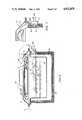
- FIG. 5is a side cross-sectional view of the broiler embodiment of the combination cooking cartridge
- FIG. 6is a top isometric view of the broiler cover shown in FIG. 6, such view taken along line 6--6 in such FIG. 5;
- FIG. 7is a side cross-sectional view of the connection between the broiler element and electric plug shown in FIG. 5, such view taken along line 7--7 in such FIG. 5;
- FIG. 8is a side cross-sectional view showing a steamer version of an alternate embodiment of the combination cooking cartridge.
- combination cooking cartridge 22includes a bottom or second pan 24, an electric resistive heating element 26, a cook'n serve vessel or first pan 28, a cover 30 and a melting tray 32.
- the second pan 24is inserted into counter 10.
- the floor of second pan 24is rectangularly shaped and made from a metal material. Cut out of the center of second pan 24 is hole 71.
- Heating element 26is mounted to the bottom of second pan 24 .
- Heating element 26is constructed with a flat CALROD and shaped into a snake-like pattern.
- Heating element 26is secured to second pan 24 with bracket 34.
- Heating element 26pertrudes through hole 24a in the back of second pan 24 and makes contact with a plug 50 (FIG. 3).
- Resting on top of heating element 26 and also connected to bracket 34is sheet 27.
- Sheet 27is constructed from a heat conducting material and contains a plurality of perforations. Sheet 27 allows heating element 26 to dissipate heat more evenly to second pan 24.
- First pan 28rests on ridge 36 in second pan 24.
- First pan 28 flooris also shaped in a rectangular pattern.
- shelf 56Along the top inner edge of first pan 28 is shelf 56.
- first pan 28has a groove 38 and ridges 40 along its bottom outside perimeter. The combination of grooves 38 and ridges 40 allow air to circulate through second pan 24.
- First pan 28may be constructed from either a metal material, such as formed steel, to provide a fast cooking device or a ceramic material such as silverstone, earthware or pyrex to provide a slow cooking device.
- the lid or cover 30rests on top of first pan 28.
- the cover 30is shaped to conform with the top edge surface of first pan 28.
- the cover 30is sloped along its outer edges to allow moisture that collects on cover 30 to drip downward into the first pan 28 below.
- Cover 30may be constructed from an earthware, pyrex or formulated steel. Further, cover 30 may also have an enamel coating.
- Connected to the top of cover 30is an insulated handle 42 to allow easy removal.
- Melting tray 32rests on the upper edge of second pan 24.
- Melting tray 32has a rectangular shaped outer edge with a rectangular trough 32a formed therein.
- Melting tray 32is used to hold various cooking utensils or to melt butter or the like.
- the second pan 24is inserted into the counter 10.
- the heating element 26, attached sheet 27 and bracket 34are inserted into the second pan 24.
- the first pan 28is then inserted over the second pan 28.
- a food rack 44is then inserted into first pan 28.
- the food rack 44is constructed out of a metal or stainless steel material.
- the food rack 44has a food supporting surface containing a first set of evenly spaced horizontal bars 44a, over a second set, perpendicular to the first set, of evenly spaced horizontal bars. Attached to the lower side of the food supporting surface are legs 44c which extend downwardly and attach to the first pans 28 upper surface.
- a steaming basket 46rather than food rack 44, may be inserted into first pan 28.
- the cover 30can then be inserted over first pan to form a cavity.
- the steamer basket 46has a rectangular shape floor 58 with sides formed to fit into first pan 28.
- the steamer basket 46has a top edge 54 that fits onto shelf 56.
- Steam basket 46 with is corresponding floor 58is typically positioned 1"-3"above the floor of first pan 28.
- Steamer basket 46also has a plurality of holes 46a, approximately 1/8" in diameter, large enough to let steam enter the cavity where the food is held but small enough not to allow food to fall through.
- the steameris typically constructed from a stainless steel material.
- first pan 28On the floor of the second pan 24 is hole 71.
- cool airenters from hole 71 and flows into the chamber 68 formed between first pan 28 and second pan 24.
- heating element 26When heating element 26 is turned on, heat is dissipated to the air between the first pan 28 and second pan 24. The heat radiates upward to heat the first pan 28. The heated air is then dissipated outward through grooves 38 between the first pan 28 and second pan 24. Without grooves 38, hot air would be collected in chamber 68, causing first pan 28 to crack.
- By allowing air to dissipate upward and out through grooves 38hot air does not collect in chamber 68 and the first pan 28 is prevented from cracking. Further, by allowing the hot air to flow along the perimeter of first pan 28, first pan 28 has a more uniform heat distribution.
- ventilation system 20may be turned on. The ventilation system 20 draws a flow cool air through hole 71 into chamber 68 and across heating element 26. Air then flows out of chamber 68, up and out groove 38 and downward into ventilation system 20.
- the ventilation system 20If the ventilation system 20 is turned off when the heating element 26 is turned on, cool air enters a chamber 68 through hole 71. The cool air then passes over heating element 26 and rises to heat the bottom first pan 28. Further, the hot air rises along the sides of first pan 28. Air flows through groove 38 on both sides of first pan 28. Due to the natural connection, hot air rises out of chamber 68, up along the sides of first pan 68, and out groove 38, thereby preventing cracking of first pan 28.
- a dish support 74is seated on shelf 56 of first pan 28 in place of the steamer pan 46 shown in FIG. 4.
- Dish support 74is made from a plastic or metal material.
- One or more warming dishesis then inserted into dish support 74.
- Warming dishes 76may be made from a metal, ceramic or pyrex material.
- first pan 28To operate the food warmer, approximately 1"-3" of water 60 is placed on the bottom of first pan 28. Heating element 26 is turned on, warming the bottom of first pan 28. The water 60 in first pan 28 is heated to a boil, thereby generating steam 60a. The rising steam 60a heats warying dishes 76, thereby waming the food (not shown).
- the rack 80 for supporting food 47has a first set of horizontal bars 80a supported on a second set of horizontal bars 80b, perpendicular to the first set of bars.
- the rackallows juice to drain between bars 80a and 80b from food 47 when the food is being cooked.
- the broiler cover 82has a metal top 82a with a handle 84.
- the metal top 82ais sized to cover the first pan 28' and second pan 24'.
- Located under the metal top 82ais a parabolic reflector 86 shaped in a snakelike pattern.
- the parabolic reflector 86is attached to the metal top with an insulated securing bracket 88.
- Parabolic reflectormay be constructed as described in U.S. Pat. No. 4,629,865.
- the electric heating element 90has a connector block 92 and jack 92a mounted at each end. Jack 92a is in electric contact with heating element 90 through connector block 92.
- Cartridge block 94Built into second pan 24' is a cartridge block 94 to which electric power is distributed to either heating element 90 or heating element 26' from the control panel 16.
- Cartridge block 94contains four jacks 94b in which to attach to a plug (not shown) disposed within cooktop frame 12. Two jacks distribute power for heating element 26' and the other two jacks 94b distribute power to electric heating element 90.
- Cartridge block 94has a receptacle 94a in which to receive jack 92a and 26' When broiler cover 82 is placed over second pan 24', jack 92a is inserted into receptacle 94. When cover is removed, jack 92a slides out of receptacle 94.
- Receive jack 26a'is permanently connected to receptacle 94.
- electric heating element 90is powered on.
- the heating element 90then becomes hot. Heat is thus reflected downward to food 47 on food holding rack 80.
- the cover 82can easily be removed during cooking. Once the cover is removed, food 47 can be turned to allow broiling on its other side.
- the combination cooking cartridge 22'can alternatively be constructed with the heating element 26' constructed within the first pan 24'.
- This embodimentis similar to the steamer shown in FIG. 3, except this embodiment contains a specially constructed first pan 24' and a second cover 100.
- the first pan 24'has a top surface and a bottom surface made out of a metal material. Sandwiched between the top and bottom surface of first pan 24' is an electric heating element 26'.
- the bottom surface of first pan 24'is insulated 102 from the heating element 26' to prevent heat from escaping out the sides and the bottom of first pan 24'.
- the second pan 28'is inserted into first pan 24'
- a steaming pan 46'is then inserted into second pan 28'.
- Steaming or pan 46'is supported by second pan 28'.
- steaming pan 46'has a plurality of holes 46a' in its sides and bottom.
- a rack 44'can be placed on steaming pan 46' to hold food 47.
- a first cover 100is inserted over second pan 28' and steamer pan 46'.
- First cover 106contains steam 60a within steamer pan 46' and second pan 28'.
- a second cover 82is placed over first cover 100 and first pan 24' to hide the first pan 24' and first cover 100 from view.
- Second cover 82also has a handle 84 to allow easy removal.
- the first pan 24'is filled with about 1"-3" of water 60.
- the heating element 26'is then turned on via control panel 16. Heating element 26' then heats second pan 28', resulting in water 60 boiling and generating steam. Steam then rises and enters the cavity within steaming pan 28' through holes 46a', thereby steaming food 47 through steaming pan 46' and rack 44'.
- the steam 60acontinues to rise and eventually contacts first cover 100 where water vapor condenses and driplets 60b form on the cover. Due to the shape of first cover 100, the driplets 60b then slide down first cover 100 and collect on the fold on the outer periphery of the cover 100b. Water 60c then drips from the fold and falls back into second pan 28'. Due to the movement of the condensed water, driplets 60c do not fall directly onto the food 47. By having the condensed drippings 60c avoid contact with the food 47, the food 47 when cooked is less soggy.
- FIG. 8is a steamer and FIG. 5 is a broiler; however, other cartridges (see FIG. 7) can be placed into first pan 28' to configure a baker or a food warmer.
Landscapes
- Engineering & Computer Science (AREA)
- Food Science & Technology (AREA)
- Cookers (AREA)
Abstract
Description
Claims (19)
Priority Applications (1)
| Application Number | Priority Date | Filing Date | Title |
|---|---|---|---|
| US07/407,673US4922079A (en) | 1988-03-18 | 1989-09-13 | Combination cooking cartridge |
Applications Claiming Priority (2)
| Application Number | Priority Date | Filing Date | Title |
|---|---|---|---|
| US17019588A | 1988-03-18 | 1988-03-18 | |
| US07/407,673US4922079A (en) | 1988-03-18 | 1989-09-13 | Combination cooking cartridge |
Related Parent Applications (1)
| Application Number | Title | Priority Date | Filing Date |
|---|---|---|---|
| US17019588AContinuation | 1988-03-18 | 1988-03-18 |
Publications (1)
| Publication Number | Publication Date |
|---|---|
| US4922079Atrue US4922079A (en) | 1990-05-01 |
Family
ID=26865825
Family Applications (1)
| Application Number | Title | Priority Date | Filing Date |
|---|---|---|---|
| US07/407,673Expired - Fee RelatedUS4922079A (en) | 1988-03-18 | 1989-09-13 | Combination cooking cartridge |
Country Status (1)
| Country | Link |
|---|---|
| US (1) | US4922079A (en) |
Cited By (48)
| Publication number | Priority date | Publication date | Assignee | Title |
|---|---|---|---|---|
| US5085505A (en)* | 1989-12-28 | 1992-02-04 | Nipox Kabushiki Kaisha | Overhead projector |
| US5134265A (en)* | 1990-02-16 | 1992-07-28 | Metcal, Inc. | Rapid heating, uniform, highly efficient griddle |
| US5227597A (en)* | 1990-02-16 | 1993-07-13 | Electric Power Research Institute | Rapid heating, uniform, highly efficient griddle |
| USD348801S (en) | 1992-10-19 | 1994-07-19 | Kathleen Romano | Frame for supporting and displaying food trays |
| US5782165A (en)* | 1992-09-01 | 1998-07-21 | Ever Splendor Enterprises Co., Ltd. | Multi-purpose cooking apparatus |
| US6089145A (en)* | 1999-07-26 | 2000-07-18 | Watson; Lance | Cooking apparatus |
| US6213006B1 (en)* | 2000-06-26 | 2001-04-10 | Lee J. Reardon | Cooking apparatus |
| US6220149B1 (en)* | 2000-07-17 | 2001-04-24 | Uni-Splendor Corp. | Barbeque grill structure |
| US6272975B1 (en) | 1999-10-28 | 2001-08-14 | Franklin Industries, Llc | Rotisserie cooking apparatus |
| US6298774B1 (en)* | 2001-02-09 | 2001-10-09 | Gary A. Latham | Barbecue grill with an automobile-shaped cover |
| US6349717B1 (en) | 2000-10-05 | 2002-02-26 | Whirlpool Corporation | Oven rack system having cutout area and insert rack |
| US6389961B1 (en)* | 2001-08-21 | 2002-05-21 | Tsann Kuen Usa Inc | Grill plate |
| WO2002039860A1 (en)* | 2000-11-16 | 2002-05-23 | Shunde Jane's Electrical Home Appliances Factory | A quick energy-saving red stoneware ceramic electric heating cooker |
| US20050034718A1 (en)* | 2003-08-15 | 2005-02-17 | Charles Van Over | Steaming device and system for residential ovens |
| US20060048768A1 (en)* | 2004-09-08 | 2006-03-09 | Michel Champagne | Dinner plate warmer |
| US20070116807A1 (en)* | 2005-11-21 | 2007-05-24 | Parsons Steven M | Food Tray |
| US20070181008A1 (en)* | 2005-10-20 | 2007-08-09 | Adam Pawlick | Cooking method and apparatus |
| US20070196552A1 (en)* | 2004-03-24 | 2007-08-23 | Robero Badin | Mobile apparatus provided with a surface for cooking by contact |
| US20070221667A1 (en)* | 2006-03-13 | 2007-09-27 | Xu Tian K | Buffet sever |
| US20080213447A1 (en)* | 2004-06-08 | 2008-09-04 | Seb S.A. | Fryer with Automatic Coating of Fat |
| US20080271611A1 (en)* | 2007-05-03 | 2008-11-06 | Gino Cocchi | Machine for heating and dispensing liquid or semi-liquid food products |
| US20090186139A1 (en)* | 2008-01-17 | 2009-07-23 | Marinela Luminita Dragan | Steam -Heat-Only, Food-Preparation Bowl Structure and Related Methodology |
| EP2468150A1 (en)* | 2010-12-22 | 2012-06-27 | BSH Bosch und Siemens Hausgeräte GmbH | Steam treatment insert |
| US20120180674A1 (en)* | 2011-01-13 | 2012-07-19 | Bradley Lewis | Grill Insert |
| US20120285935A1 (en)* | 2011-05-10 | 2012-11-15 | Hitachi High-Technologies Corporation | Heat treatment apparatus |
| US20130011526A1 (en)* | 2005-10-20 | 2013-01-10 | Conagra Foods Rdm, Inc. | Cooking method and apparatus |
| US20130112670A1 (en)* | 2011-11-08 | 2013-05-09 | Hitachi High-Technologies Corporation | Heat treatment apparatus |
| US8534188B1 (en) | 2011-09-01 | 2013-09-17 | Barbara A. Winfield | Cheesecake pan system |
| US20140083304A1 (en)* | 2012-09-27 | 2014-03-27 | Zhipeng He | Puree vegetable soup maker |
| US8866056B2 (en) | 2007-03-02 | 2014-10-21 | Conagra Foods Rdm, Inc. | Multi-component packaging system and apparatus |
| USD717162S1 (en) | 2012-06-12 | 2014-11-11 | Conagra Foods Rdm, Inc. | Container |
| US9027825B2 (en) | 2012-06-12 | 2015-05-12 | Conagra Foods Rdm, Inc. | Container assembly and foldable container system |
| US9132951B2 (en) | 2005-11-23 | 2015-09-15 | Conagra Foods Rdm, Inc. | Food tray |
| US9211030B2 (en) | 2005-10-20 | 2015-12-15 | Conagra Foods Rdm, Inc. | Steam cooking apparatus |
| US9532676B1 (en) | 2011-09-01 | 2017-01-03 | Barbara A. Winfield | Cheesecake pan system |
| US9675186B2 (en) | 2010-08-31 | 2017-06-13 | Hussmann Corporation | Merchandiser including venting frame for top containers |
| WO2017201530A1 (en)* | 2016-05-20 | 2017-11-23 | Ovention, Inc. | Systems and methods for an oven with a movable cook surface |
| EP3287700A1 (en)* | 2016-08-23 | 2018-02-28 | Electrolux Appliances Aktiebolag | Oven and oven tray for smoking or aromatic vapour treatment applications |
| EP3343115A1 (en)* | 2016-12-27 | 2018-07-04 | LG Electronics Inc. | Cooking appliance |
| WO2018219709A1 (en)* | 2017-05-31 | 2018-12-06 | Electrolux Appliances Aktiebolag | Cooker with vapor generator |
| US20190101293A1 (en)* | 2017-09-29 | 2019-04-04 | Lg Electronics Inc. | Cooking apparatus |
| CN110604463A (en)* | 2018-06-14 | 2019-12-24 | Bsh家用电器有限公司 | Method for operating a cooking appliance and cooking appliance |
| US10743715B2 (en) | 2015-08-10 | 2020-08-18 | Duke Manufacturing Co. | Food serving station and associated appliances and methods |
| US11019953B2 (en) | 2016-12-27 | 2021-06-01 | Lg Electronics Inc. | Vacuum cooking appliance |
| US20210177201A1 (en)* | 2015-10-08 | 2021-06-17 | Les Accessoires Multifonctions Inc. | Modular barbecue system and kits therefore |
| CN114073398A (en)* | 2020-08-13 | 2022-02-22 | 蔡建佑 | Hasp type socket steam function combination device |
| US11639797B2 (en) | 2015-05-05 | 2023-05-02 | Ovention, Inc. | Cooking oven having an active vent |
| US11832764B2 (en) | 2017-10-13 | 2023-12-05 | Lg Electronics Inc. | Cooking apparatus |
Citations (22)
| Publication number | Priority date | Publication date | Assignee | Title |
|---|---|---|---|---|
| US1378566A (en)* | 1919-09-19 | 1921-05-17 | Gen Electric | Electric cooker |
| US1383971A (en)* | 1920-09-11 | 1921-07-05 | Audley Pierce J | Cooking utensil |
| US1415049A (en)* | 1920-10-07 | 1922-05-09 | Sterolectric Company | Fireless cooker |
| US1485292A (en)* | 1918-12-14 | 1924-02-26 | Theroz Company | Sterilizer |
| US1550707A (en)* | 1923-02-13 | 1925-08-25 | Jacob L Moore | Stove |
| US2182682A (en)* | 1936-12-08 | 1939-12-05 | Edison General Elec Appliance | Food warming table |
| US2187888A (en)* | 1936-05-21 | 1940-01-23 | Nachumsohn Irving | Cooking apparatus |
| FR870647A (en)* | 1940-11-21 | 1942-03-18 | Container with athermal walls, especially for domestic applications | |
| US2329760A (en)* | 1940-02-03 | 1943-09-21 | Westinghouse Electric & Mfg Co | Cooking appliance |
| FR984491A (en)* | 1943-10-05 | 1951-07-06 | Improvements to electrical appliances for cooking food | |
| FR1026817A (en)* | 1949-08-19 | 1953-05-05 | Kitchen electric appliance | |
| US2695352A (en)* | 1952-10-22 | 1954-11-23 | Dekold Nickolas | Hot table |
| US2695947A (en)* | 1952-10-01 | 1954-11-30 | Gen Electric | Deep fat frying attachment for electric ranges |
| US2715898A (en)* | 1951-09-27 | 1955-08-23 | Gen Electric | Food warming and conditioning device |
| US2831956A (en)* | 1954-01-19 | 1958-04-22 | Gen Motors Corp | Domestic appliance |
| CA733201A (en)* | 1966-04-26 | H. Barker Harry | Electric cooking apparatus | |
| US3364844A (en)* | 1966-05-19 | 1968-01-23 | Gen Electric | Food steamer with multi-level food supporting means |
| US3443063A (en)* | 1967-02-27 | 1969-05-06 | Harvic Mfg Corp | Food heating and conditioning device |
| US3641926A (en)* | 1969-07-02 | 1972-02-15 | James M Williams | Combination of cooking utensils |
| US3869595A (en)* | 1974-06-19 | 1975-03-04 | Walter Collins | Insulated heated lunch box |
| FR2416427A1 (en)* | 1978-02-02 | 1979-08-31 | Pedrini Ivano | PORTABLE COOKING APPLIANCE |
| GB2185876A (en)* | 1985-12-20 | 1987-08-05 | Matsushita Electric Industrial Co Ltd | Electric cooker |
- 1989
- 1989-09-13USUS07/407,673patent/US4922079A/ennot_activeExpired - Fee Related
Patent Citations (22)
| Publication number | Priority date | Publication date | Assignee | Title |
|---|---|---|---|---|
| CA733201A (en)* | 1966-04-26 | H. Barker Harry | Electric cooking apparatus | |
| US1485292A (en)* | 1918-12-14 | 1924-02-26 | Theroz Company | Sterilizer |
| US1378566A (en)* | 1919-09-19 | 1921-05-17 | Gen Electric | Electric cooker |
| US1383971A (en)* | 1920-09-11 | 1921-07-05 | Audley Pierce J | Cooking utensil |
| US1415049A (en)* | 1920-10-07 | 1922-05-09 | Sterolectric Company | Fireless cooker |
| US1550707A (en)* | 1923-02-13 | 1925-08-25 | Jacob L Moore | Stove |
| US2187888A (en)* | 1936-05-21 | 1940-01-23 | Nachumsohn Irving | Cooking apparatus |
| US2182682A (en)* | 1936-12-08 | 1939-12-05 | Edison General Elec Appliance | Food warming table |
| US2329760A (en)* | 1940-02-03 | 1943-09-21 | Westinghouse Electric & Mfg Co | Cooking appliance |
| FR870647A (en)* | 1940-11-21 | 1942-03-18 | Container with athermal walls, especially for domestic applications | |
| FR984491A (en)* | 1943-10-05 | 1951-07-06 | Improvements to electrical appliances for cooking food | |
| FR1026817A (en)* | 1949-08-19 | 1953-05-05 | Kitchen electric appliance | |
| US2715898A (en)* | 1951-09-27 | 1955-08-23 | Gen Electric | Food warming and conditioning device |
| US2695947A (en)* | 1952-10-01 | 1954-11-30 | Gen Electric | Deep fat frying attachment for electric ranges |
| US2695352A (en)* | 1952-10-22 | 1954-11-23 | Dekold Nickolas | Hot table |
| US2831956A (en)* | 1954-01-19 | 1958-04-22 | Gen Motors Corp | Domestic appliance |
| US3364844A (en)* | 1966-05-19 | 1968-01-23 | Gen Electric | Food steamer with multi-level food supporting means |
| US3443063A (en)* | 1967-02-27 | 1969-05-06 | Harvic Mfg Corp | Food heating and conditioning device |
| US3641926A (en)* | 1969-07-02 | 1972-02-15 | James M Williams | Combination of cooking utensils |
| US3869595A (en)* | 1974-06-19 | 1975-03-04 | Walter Collins | Insulated heated lunch box |
| FR2416427A1 (en)* | 1978-02-02 | 1979-08-31 | Pedrini Ivano | PORTABLE COOKING APPLIANCE |
| GB2185876A (en)* | 1985-12-20 | 1987-08-05 | Matsushita Electric Industrial Co Ltd | Electric cooker |
Non-Patent Citations (2)
| Title |
|---|
| Jenn Air Quality Appliances for Distinctive Kitchens; Jenn Air Company, Indiana; Jul. 1987.* |
| Jenn-Air Quality Appliances for Distinctive Kitchens; Jenn-Air Company, Indiana; Jul. 1987. |
Cited By (74)
| Publication number | Priority date | Publication date | Assignee | Title |
|---|---|---|---|---|
| US5085505A (en)* | 1989-12-28 | 1992-02-04 | Nipox Kabushiki Kaisha | Overhead projector |
| US5134265A (en)* | 1990-02-16 | 1992-07-28 | Metcal, Inc. | Rapid heating, uniform, highly efficient griddle |
| US5227597A (en)* | 1990-02-16 | 1993-07-13 | Electric Power Research Institute | Rapid heating, uniform, highly efficient griddle |
| US5782165A (en)* | 1992-09-01 | 1998-07-21 | Ever Splendor Enterprises Co., Ltd. | Multi-purpose cooking apparatus |
| USD348801S (en) | 1992-10-19 | 1994-07-19 | Kathleen Romano | Frame for supporting and displaying food trays |
| US6089145A (en)* | 1999-07-26 | 2000-07-18 | Watson; Lance | Cooking apparatus |
| US6272975B1 (en) | 1999-10-28 | 2001-08-14 | Franklin Industries, Llc | Rotisserie cooking apparatus |
| US6213006B1 (en)* | 2000-06-26 | 2001-04-10 | Lee J. Reardon | Cooking apparatus |
| US6220149B1 (en)* | 2000-07-17 | 2001-04-24 | Uni-Splendor Corp. | Barbeque grill structure |
| US6349717B1 (en) | 2000-10-05 | 2002-02-26 | Whirlpool Corporation | Oven rack system having cutout area and insert rack |
| WO2002039860A1 (en)* | 2000-11-16 | 2002-05-23 | Shunde Jane's Electrical Home Appliances Factory | A quick energy-saving red stoneware ceramic electric heating cooker |
| US6298774B1 (en)* | 2001-02-09 | 2001-10-09 | Gary A. Latham | Barbecue grill with an automobile-shaped cover |
| US6389961B1 (en)* | 2001-08-21 | 2002-05-21 | Tsann Kuen Usa Inc | Grill plate |
| US20050034718A1 (en)* | 2003-08-15 | 2005-02-17 | Charles Van Over | Steaming device and system for residential ovens |
| US7100598B2 (en)* | 2003-08-15 | 2006-09-05 | Charles Van Over | Steaming device and system for residential ovens |
| US20070196552A1 (en)* | 2004-03-24 | 2007-08-23 | Robero Badin | Mobile apparatus provided with a surface for cooking by contact |
| US8166870B2 (en)* | 2004-03-24 | 2012-05-01 | Smartech Italia S.P.A. | Mobile apparatus provided with a surface for cooking by contact |
| US20080213447A1 (en)* | 2004-06-08 | 2008-09-04 | Seb S.A. | Fryer with Automatic Coating of Fat |
| US9301644B2 (en)* | 2004-06-08 | 2016-04-05 | Seb S.A. | Fryer with automatic coating of fat |
| US20060048768A1 (en)* | 2004-09-08 | 2006-03-09 | Michel Champagne | Dinner plate warmer |
| US8850964B2 (en)* | 2005-10-20 | 2014-10-07 | Conagra Foods Rdm, Inc. | Cooking method and apparatus |
| US20130011526A1 (en)* | 2005-10-20 | 2013-01-10 | Conagra Foods Rdm, Inc. | Cooking method and apparatus |
| US9505542B2 (en) | 2005-10-20 | 2016-11-29 | Conagra Foods Rdm, Inc. | Cooking method and apparatus |
| US9211030B2 (en) | 2005-10-20 | 2015-12-15 | Conagra Foods Rdm, Inc. | Steam cooking apparatus |
| US20070181008A1 (en)* | 2005-10-20 | 2007-08-09 | Adam Pawlick | Cooking method and apparatus |
| US10569949B2 (en)* | 2005-10-20 | 2020-02-25 | Conagra Foods Rdm, Inc. | Cooking method and apparatus |
| US8887918B2 (en) | 2005-11-21 | 2014-11-18 | Conagra Foods Rdm, Inc. | Food tray |
| US20070116807A1 (en)* | 2005-11-21 | 2007-05-24 | Parsons Steven M | Food Tray |
| US9815607B2 (en) | 2005-11-21 | 2017-11-14 | Conagra Foods Rdm, Inc. | Food tray |
| US9132951B2 (en) | 2005-11-23 | 2015-09-15 | Conagra Foods Rdm, Inc. | Food tray |
| US20070221667A1 (en)* | 2006-03-13 | 2007-09-27 | Xu Tian K | Buffet sever |
| US8866056B2 (en) | 2007-03-02 | 2014-10-21 | Conagra Foods Rdm, Inc. | Multi-component packaging system and apparatus |
| US20080271611A1 (en)* | 2007-05-03 | 2008-11-06 | Gino Cocchi | Machine for heating and dispensing liquid or semi-liquid food products |
| US20090186139A1 (en)* | 2008-01-17 | 2009-07-23 | Marinela Luminita Dragan | Steam -Heat-Only, Food-Preparation Bowl Structure and Related Methodology |
| US8813635B2 (en)* | 2008-01-17 | 2014-08-26 | Marinela Luminita Dragan | Steam-heat-only, food-preparation bowl structure and related methodology |
| US9675186B2 (en) | 2010-08-31 | 2017-06-13 | Hussmann Corporation | Merchandiser including venting frame for top containers |
| EP2468150A1 (en)* | 2010-12-22 | 2012-06-27 | BSH Bosch und Siemens Hausgeräte GmbH | Steam treatment insert |
| US20120180674A1 (en)* | 2011-01-13 | 2012-07-19 | Bradley Lewis | Grill Insert |
| US20120285935A1 (en)* | 2011-05-10 | 2012-11-15 | Hitachi High-Technologies Corporation | Heat treatment apparatus |
| US8569647B2 (en)* | 2011-05-10 | 2013-10-29 | Hitachi High-Technologies Corporation | Heat treatment apparatus |
| US8534188B1 (en) | 2011-09-01 | 2013-09-17 | Barbara A. Winfield | Cheesecake pan system |
| US9532676B1 (en) | 2011-09-01 | 2017-01-03 | Barbara A. Winfield | Cheesecake pan system |
| US9490104B2 (en)* | 2011-11-08 | 2016-11-08 | Hitachi High-Technologies Corporation | Heat treatment apparatus |
| US20130112670A1 (en)* | 2011-11-08 | 2013-05-09 | Hitachi High-Technologies Corporation | Heat treatment apparatus |
| USD717162S1 (en) | 2012-06-12 | 2014-11-11 | Conagra Foods Rdm, Inc. | Container |
| US9027825B2 (en) | 2012-06-12 | 2015-05-12 | Conagra Foods Rdm, Inc. | Container assembly and foldable container system |
| US20140083304A1 (en)* | 2012-09-27 | 2014-03-27 | Zhipeng He | Puree vegetable soup maker |
| US11639797B2 (en) | 2015-05-05 | 2023-05-02 | Ovention, Inc. | Cooking oven having an active vent |
| US10743715B2 (en) | 2015-08-10 | 2020-08-18 | Duke Manufacturing Co. | Food serving station and associated appliances and methods |
| US12035846B2 (en) | 2015-08-10 | 2024-07-16 | Duke Manufacturing Co. | Food serving station and associated appliances and methods |
| US12127709B2 (en)* | 2015-10-08 | 2024-10-29 | Les Accessoires Multifonctions Inc. | Modular barbecue system and kits therefore |
| US20210177201A1 (en)* | 2015-10-08 | 2021-06-17 | Les Accessoires Multifonctions Inc. | Modular barbecue system and kits therefore |
| WO2017201530A1 (en)* | 2016-05-20 | 2017-11-23 | Ovention, Inc. | Systems and methods for an oven with a movable cook surface |
| US11388904B2 (en) | 2016-05-20 | 2022-07-19 | Ovention, Inc. | Systems and methods for an oven with a movable cook surface |
| US10765119B2 (en) | 2016-05-20 | 2020-09-08 | Ovention, Inc. | Systems for an oven with upper and lower heat packs |
| EP3287700A1 (en)* | 2016-08-23 | 2018-02-28 | Electrolux Appliances Aktiebolag | Oven and oven tray for smoking or aromatic vapour treatment applications |
| US20210259454A1 (en)* | 2016-12-27 | 2021-08-26 | Lg Electronics Inc. | Vacuum cooking appliance |
| US12114799B2 (en)* | 2016-12-27 | 2024-10-15 | Lg Electronics Inc. | Vacuum cooking appliance |
| US10863589B2 (en) | 2016-12-27 | 2020-12-08 | Lg Electronics Inc. | Cooking appliance |
| EP3343115A1 (en)* | 2016-12-27 | 2018-07-04 | LG Electronics Inc. | Cooking appliance |
| US12082315B2 (en) | 2016-12-27 | 2024-09-03 | Lg Electronics Inc. | Cooking appliance |
| US11019953B2 (en) | 2016-12-27 | 2021-06-01 | Lg Electronics Inc. | Vacuum cooking appliance |
| KR20200013655A (en)* | 2017-05-31 | 2020-02-07 | 일렉트로룩스 어플라이언스 아크티에볼레그 | Range with steam generator |
| CN108980907A (en)* | 2017-05-31 | 2018-12-11 | 伊莱克斯家用电器股份公司 | Cooking stove |
| JP2020522667A (en)* | 2017-05-31 | 2020-07-30 | エレクトロラックス アプライアンシス アクティエボラーグ | Cooker with steam generator |
| WO2018219709A1 (en)* | 2017-05-31 | 2018-12-06 | Electrolux Appliances Aktiebolag | Cooker with vapor generator |
| US20210148574A1 (en)* | 2017-09-29 | 2021-05-20 | Lg Electronics Inc. | Cooking apparatus |
| US20190101293A1 (en)* | 2017-09-29 | 2019-04-04 | Lg Electronics Inc. | Cooking apparatus |
| US11846431B2 (en)* | 2017-09-29 | 2023-12-19 | Lg Electronics Inc. | Cooking apparatus |
| US10935247B2 (en)* | 2017-09-29 | 2021-03-02 | Lg Electronics Inc. | Cooking apparatus |
| US11832764B2 (en) | 2017-10-13 | 2023-12-05 | Lg Electronics Inc. | Cooking apparatus |
| CN110604463A (en)* | 2018-06-14 | 2019-12-24 | Bsh家用电器有限公司 | Method for operating a cooking appliance and cooking appliance |
| CN114073398B (en)* | 2020-08-13 | 2023-02-28 | 蔡建佑 | Hasp type socket steam function combination device |
| CN114073398A (en)* | 2020-08-13 | 2022-02-22 | 蔡建佑 | Hasp type socket steam function combination device |
Similar Documents
| Publication | Publication Date | Title |
|---|---|---|
| US4922079A (en) | Combination cooking cartridge | |
| US5782165A (en) | Multi-purpose cooking apparatus | |
| US11585536B2 (en) | Cooking appliance | |
| US5948301A (en) | Food thermalization device | |
| US4889972A (en) | Multi-functional electrically activated stove | |
| US6293271B1 (en) | Multifunctional cooking pot | |
| US11937736B2 (en) | Cooking appliance with conductive heating capabilities | |
| US3693534A (en) | Cooking device | |
| US6516709B1 (en) | Apparatus for steaming food | |
| US6089145A (en) | Cooking apparatus | |
| US3457852A (en) | Reversible multiple cooking oven,steamer,grill and griddle | |
| USRE31765E (en) | Counter-top oven | |
| US3713379A (en) | Bacon broiler | |
| US20030213790A1 (en) | Small electric oven | |
| US3938495A (en) | Grilling apparatus with supporting surface | |
| KR20120121497A (en) | Steamed and Barbecue combined pot | |
| WO2012174702A1 (en) | Cooking appliance | |
| US2001285A (en) | Electric cooker | |
| US2457877A (en) | Cooking unit | |
| GB2080097A (en) | Appliance for cooking various foods | |
| CA1307122C (en) | Combination cooking cartridge | |
| KR200495549Y1 (en) | Electronic oven of drawer type | |
| KR102309098B1 (en) | Single Electric Cooker using for highlight | |
| JPH0643613Y2 (en) | Roasting machine | |
| CN220588113U (en) | Cooking equipment and heat source protection components |
Legal Events
| Date | Code | Title | Description |
|---|---|---|---|
| FEPP | Fee payment procedure | Free format text:PAYOR NUMBER ASSIGNED (ORIGINAL EVENT CODE: ASPN); ENTITY STATUS OF PATENT OWNER: LARGE ENTITY | |
| FPAY | Fee payment | Year of fee payment:4 | |
| FPAY | Fee payment | Year of fee payment:8 | |
| AS | Assignment | Owner name:RAYTHEON APPLIANCES, INC., IOWA Free format text:ASSIGNMENT OF ASSIGNORS INTEREST;ASSIGNOR:RAYTHEON COMPANY;REEL/FRAME:008869/0374 Effective date:19970909 | |
| AS | Assignment | Owner name:AMANA COMPANY, L.P., A DELAWARE CORPORATION, IOWA Free format text:MERGER;ASSIGNOR:RAYTHEON APPLIANCES, INC.;REEL/FRAME:009297/0657 Effective date:19970910 | |
| AS | Assignment | Owner name:MAYTAG CORPORATION, IOWA Free format text:ASSIGNMENT OF ASSIGNORS INTEREST;ASSIGNOR:AMANA APPLIANCE COMPANY, L.P.;REEL/FRAME:012166/0406 Effective date:20010731 | |
| REMI | Maintenance fee reminder mailed | ||
| LAPS | Lapse for failure to pay maintenance fees | ||
| STCH | Information on status: patent discontinuation | Free format text:PATENT EXPIRED DUE TO NONPAYMENT OF MAINTENANCE FEES UNDER 37 CFR 1.362 | |
| FP | Lapsed due to failure to pay maintenance fee | Effective date:20020501 |