US4921129A - Liquid dispensing module - Google Patents
Liquid dispensing moduleDownload PDFInfo
- Publication number
- US4921129A US4921129AUS07/217,303US21730388AUS4921129AUS 4921129 AUS4921129 AUS 4921129AUS 21730388 AUS21730388 AUS 21730388AUS 4921129 AUS4921129 AUS 4921129A
- Authority
- US
- United States
- Prior art keywords
- container
- combination according
- liquid
- pipe
- module
- Prior art date
- Legal status (The legal status is an assumption and is not a legal conclusion. Google has not performed a legal analysis and makes no representation as to the accuracy of the status listed.)
- Expired - Fee Related
Links
- 239000007788liquidSubstances0.000titleclaimsabstractdescription70
- 239000000523sampleSubstances0.000claimsabstractdescription24
- 239000004033plasticSubstances0.000claimsabstractdescription6
- 230000008878couplingEffects0.000claimsdescription4
- 238000010168coupling processMethods0.000claimsdescription4
- 238000005859coupling reactionMethods0.000claimsdescription4
- 239000004020conductorSubstances0.000claims2
- 239000000344soapSubstances0.000abstractdescription29
- 238000004140cleaningMethods0.000abstractdescription27
- XLYOFNOQVPJJNP-UHFFFAOYSA-NwaterSubstancesOXLYOFNOQVPJJNP-UHFFFAOYSA-N0.000description12
- 239000012530fluidSubstances0.000description8
- 239000002184metalSubstances0.000description3
- 239000000203mixtureSubstances0.000description3
- 238000012544monitoring processMethods0.000description3
- 238000010276constructionMethods0.000description2
- 239000012528membraneSubstances0.000description2
- 239000007921spraySubstances0.000description2
- 239000000126substanceSubstances0.000description2
- 241000522254CassiaSpecies0.000description1
- 235000014489Cinnamomum aromaticumNutrition0.000description1
- 238000006243chemical reactionMethods0.000description1
- 235000013409condimentsNutrition0.000description1
- 238000011109contaminationMethods0.000description1
- 230000000694effectsEffects0.000description1
- 239000000945fillerSubstances0.000description1
- 239000000463materialSubstances0.000description1
- 238000000034methodMethods0.000description1
- 239000008267milkSubstances0.000description1
- 210000004080milkAnatomy0.000description1
- 235000013336milkNutrition0.000description1
- 238000012986modificationMethods0.000description1
- 230000004048modificationEffects0.000description1
- 239000002991molded plasticSubstances0.000description1
- 238000009428plumbingMethods0.000description1
- 238000005406washingMethods0.000description1
Images


Classifications
- G—PHYSICS
- G01—MEASURING; TESTING
- G01F—MEASURING VOLUME, VOLUME FLOW, MASS FLOW OR LIQUID LEVEL; METERING BY VOLUME
- G01F23/00—Indicating or measuring liquid level or level of fluent solid material, e.g. indicating in terms of volume or indicating by means of an alarm
- G01F23/22—Indicating or measuring liquid level or level of fluent solid material, e.g. indicating in terms of volume or indicating by means of an alarm by measuring physical variables, other than linear dimensions, pressure or weight, dependent on the level to be measured, e.g. by difference of heat transfer of steam or water
- G01F23/24—Indicating or measuring liquid level or level of fluent solid material, e.g. indicating in terms of volume or indicating by means of an alarm by measuring physical variables, other than linear dimensions, pressure or weight, dependent on the level to be measured, e.g. by difference of heat transfer of steam or water by measuring variations of resistance of resistors due to contact with conductor fluid
- G01F23/241—Indicating or measuring liquid level or level of fluent solid material, e.g. indicating in terms of volume or indicating by means of an alarm by measuring physical variables, other than linear dimensions, pressure or weight, dependent on the level to be measured, e.g. by difference of heat transfer of steam or water by measuring variations of resistance of resistors due to contact with conductor fluid for discrete levels
- G01F23/242—Mounting arrangements for electrodes
- A—HUMAN NECESSITIES
- A47—FURNITURE; DOMESTIC ARTICLES OR APPLIANCES; COFFEE MILLS; SPICE MILLS; SUCTION CLEANERS IN GENERAL
- A47L—DOMESTIC WASHING OR CLEANING; SUCTION CLEANERS IN GENERAL
- A47L15/00—Washing or rinsing machines for crockery or tableware
- A47L15/42—Details
- A47L15/44—Devices for adding cleaning agents; Devices for dispensing cleaning agents, rinsing aids or deodorants
- D—TEXTILES; PAPER
- D06—TREATMENT OF TEXTILES OR THE LIKE; LAUNDERING; FLEXIBLE MATERIALS NOT OTHERWISE PROVIDED FOR
- D06F—LAUNDERING, DRYING, IRONING, PRESSING OR FOLDING TEXTILE ARTICLES
- D06F39/00—Details of washing machines not specific to a single type of machines covered by groups D06F9/00 - D06F27/00
- D06F39/02—Devices for adding soap or other washing agents
- D06F39/022—Devices for adding soap or other washing agents in a liquid state
- Y—GENERAL TAGGING OF NEW TECHNOLOGICAL DEVELOPMENTS; GENERAL TAGGING OF CROSS-SECTIONAL TECHNOLOGIES SPANNING OVER SEVERAL SECTIONS OF THE IPC; TECHNICAL SUBJECTS COVERED BY FORMER USPC CROSS-REFERENCE ART COLLECTIONS [XRACs] AND DIGESTS
- Y10—TECHNICAL SUBJECTS COVERED BY FORMER USPC
- Y10T—TECHNICAL SUBJECTS COVERED BY FORMER US CLASSIFICATION
- Y10T137/00—Fluid handling
- Y10T137/8158—With indicator, register, recorder, alarm or inspection means
- Y10T137/8342—Liquid level responsive indicator, recorder or alarm
Definitions
- the system of the present inventionis particularly useful in conjunction with modern lavage devices where the cleaning solution is supplied through the liquid jet cleaning arms.
- itis necessary to replenish the soap or other cleaning solution from time to time as it is consumed in the machine.
- thisis accomplished by pouring cleaning solution or liquid soap into a reservoir which is permanently built into the lavage machine.
- the refilling of such a reservoiris from a large bottle or other container which is used to store the cleaning solution and which most frequently holds a greater amount of cleaning solution than the reservoir in the lavage machine.
- Such soap dispensersare widely used in public restrooms to dispense a measured amount of liquid soap onto the hands of the user. Since the soap is stored in a closed container, no unsightly dirty soap bars are left on the counter top. Furthermore, the use of liquid soap within a dispensing container prevents the theft of or removal of soap from the restroom or the like where it is used.
- Liquid soap dispensers of the type typically used in public restrooms and which employ a modular or throw-away container for replenishing the soapare disclosed in the Pat. Nos. to Darr No. 2,965,267; Cassia No. 4,245,627; and Steiner No. 4,391,309.
- the dispensers which are disclosed in all three of these patentsuse a replaceable liquid container which is placed upside down in a container holding portion of the dispenser. During placement of a new liquid container, a puncturing or piercing member opens the new container to permit the fluid in it to flow into a sump located immediately below the container. This essentially prevents spilling of liquid soap from the new container during the refilling operation.
- the DeHarde U.S. Pat. No. 3,465,916discloses a sump system in which bottles for various liquids are first opened and then inserted upside down over the sumps. Consequently, this patent is similar to the Perrin and Batlas Patents.
- the device of DeHardeincludes electrical liquid level monitoring sensors. These sensors are built into and remain in place in the sump.
- the DeHarde deviceis refilled from standard bottles or containers for the various liquids which are to be dispensed from the apparatus. Such containers first are opened and then poured into the sump.
- an improved disposable liquid dispensing modulefor use in equipment having apparatus for withdrawing liquid therefrom, such as lavage machines and the like.
- Such a moduleideally, should be self-contained and capable of simple and effective replacement with a minimum possibility of spillage of the cleaning solution.
- a disposable liquid dispensing moduleis made for use with equipment having apparatus in it for withdrawing liquid from the module.
- the moduleitself comprises a hollow container for holding the liquid to be dispensed.
- a liquid level sensoris mounted in the container for use in conjunction with the liquid withdrawing apparatus in the equipment to provide an indication when the level of liquid in the container is less than a pre-established minimum threshold.
- a liquid withdrawal openingis provided in the container for connection with the withdrawing apparatus.
- An indicator couplingis also provided in the container for connection to the liquid level sensing device for releaseable connection with an indicator in the equipment to provide an indication of the level of liquid in the container.
- a provisionalso is made for closing the liquid withdrawal opening during shipping and storage of the container.
- FIG. 1is a diagrammatic representation of a lavage machine in which a preferred embodiment of the invention is used;
- FIG. 2is a top perspective view of a preferred embodiment of the invention
- FIG. 3is a side view of the embodiment shown in FIG. 2;
- FIG. 4is a bottom view of the embodiment shown in FIG. 2;
- FIG. 5is an enlarged top view of a portion of the embodiment shown in FIGS. 2, 3 and 4;
- FIG. 6is a cross-sectional view across the width of the embodiment shown in FIG. 3;
- FIG. 7is a top view of a portion of the embodiment shown in FIG. 2;
- FIGS. 8 and 9are cross-sectional side and end views, respectively, of the portion of the device shown in FIG. 7;
- FIG. 10is an enlarged view of a portion of the device shown in FIGS. 7 and 8;
- FIG. 11is a cross-sectional view across the length of the assembly of the embodiment of FIGS. 2 and 3.
- FIG. 1is a diagrammatic representation of a lavage machine 10 which is of the type disclosed in the above-identified co-pending application Ser. No. 07/176,361. Since the actual construction of the lavage machine essentially can be of any known type, details of that construction have not been shown in the diagrammatic representation of the machine in FIG. 1.
- the lavage machine 10includes a pair of spray nozzle manifolds 12 and 14 for washing the left and right hands, respectively, of a user. These manifolds may be of any desired type.
- wateris obtained from a standard municipal water supply line 16 (preferably after being heated in a water heater). Normally, water from the supply line 16 is prevented from being applied to the manifolds 12 and 14 by closed electric valves 18 and 19.
- a control system 15, supplied with suitable operating power from a source 9 (not shown)is operated to open both of the valves 18 and 19.
- Some of the water from the supply 16passes directly through the valve 18 and through a conventional plumbing "Tee" 26, to a pulsator 28.
- Wateralso is supplied from the line 16 through the valve 19 over a line 20 into a venturi "Tee” 21 connected to a modular liquid soap or liquid cleaning solution dispenser 23.
- the water passing through the venturi 21withdraws a predetermined amount of soap or cleaning solution from the dispensing module 23 through a flexible withdrawal hose 35.
- the soap which is withdrawn from the dispenser 23is mixed with the water and is provided through a pipe 24 to the "Tee" 26. There it is mixed with the water flowing through the valve 18 from the water supply, and this mixture is supplied as a combination water/soap mixture to the pulsator 28.
- the pulsator 28is used to provide cylically varying pulses of water, 180° out of phase, through a pair of outlet pipes 31 and 30, respectively, to the spray manifolds 12 and 14 in the lavage machine.
- the manner in which this operation is effected by the pulsator 28is described in detail in co-pending application Ser. No. 07/176,361. Briefly, however, operation of the pulsator 26 to effect the cleaning function is provided by a motor 29, which is turned on by the control system 15 at the time the valves 18 and 19 are opened. A drain (not shown) removes the spent fluid from the machine. At the end of a lavage cycle, the control system 15 closes the valves 18 and 19 and turns off the motor 29. The system then remains in this standby state until the next time it is to be used.
- the soap dispensing module 23has a liquid level sensor built into it to provide signals over a pair of wires 36 and 37 to the control system 15. These wires are connected to the liquid level sensors, located within the module 23, at a cap or plug 38. Whenever the level of the soap or cleaning solution within the dispensing module 23 is nearly exhausted, an indication is provided over the wires 36 and 37 to control system 15 which causes an indicator light 32 on a front panel to be turned on to alert users of the machine that the cleaning solution or soap is used up or is nearly used up and that the dispenser module 23 needs to be replaced.
- the module 23may be located at any convenient place in the machine. Typically the module is accessible through the front or side behind a hinged door or panel 40. Normally, when the machine is in use, no attention whatsoever needs to be paid to the module 23 or the amount of cleaning solution in it.
- the door 40is opened and the module 23 is withdrawn outwardly through the door 40 for replacement.
- the plug or connector 38is detached from the module 23 which then is thrown away.
- a new module 23then is attached to the plug 38, is inserted through the open door 40 to the position shown in FIG. 1, and the machine is ready for continued operation until the level of cleaning solution in the new module is depleated. At such time, the foregoing replacement cycle is repeated.
- FIGS. 2 through 6illustrate details of the module 23.
- the soap or cleaning solution dispensing module 23is in the form of a low profile, elongated container, the vertical height of which is less than both the width and length and in which the length is approximately one and one-half (11/2 ) times the width. These dimensions, however, are not critical but have been found to be particularly well suited with the lavage machine of the type shown in FIG. 1. Because of the low profile of the dispensing module 23, it may be located in an area near the bottom of the lavage machine where limited vertical space is present.
- the module 23is made of any suitable disposable material and typically is in the form of an molded plastic "bottle" having the shape shown in FIGS. 2, 3 and 4.
- the end of the module which is adjacent the door 40 in the machinehas a handle 41 formed in it.
- This handletypically is hollow, so that cleaning solution may flow into and out of it.
- FIGS. 2 through 4By forming the handle 41 as illustrated in FIGS. 2 through 4, withdrawal of and replacement of different modules 23 in the lavage machine shown in FIG. 1 is readily effected.
- a pair of projections 44are provided on the end of the module opposite the handle 41 and a circular enlarged sump 45 is provided at the bottom of the module near the handle 41. The relationship of this sump to the bottom of the module 23 is illustrated most clearly in FIG. 6.
- a threaded "fill" opening 50(shown most clearly in FIG. 6). Cleaning solution or liquid soap is poured through the opening 50 during the filling operation of the module 23.
- a closure cap 55is permanently bonded (such as by heat staking) to an inwardly turned ledge 51 formed at the top of the opening 50 to seal the opening.
- the cap 55as shown most clearly in FIGS. 5 and 6, has a single probe 63 or a pair of electrically conductive probes 62 and 63 extending downwardly through it.
- the probe 62has a length which causes it to extend to the bottom of the sump 45 or to a position close to the bottom.
- the probe 63is shortr than the probe 62 (when it is used) and extends to a position which is indicated in FIG. 6 as being slightly above the bottom of the main portion of the dispenser module 23.
- the center of the cap 55has a liquid withdrawal opening 57 in it.
- the dimensions of the opening 57are selected to conform to the outer dimensions of a withdrawal probe which is subsequently inserted through the opening 57 when a new module is to be placed in operation in a lavage machine of the type shown in FIG. 1.
- a temporary shipping cap 65is screwed downwardly onto the neck 50 to seal the opening 57 and to cover a pair of connector receiving openings 58 and 59 which electrically interconnect with the upper ends of the probes 62 and 63.
- the shipping cap 65may be any suitable type of disposable plastic cap or the like typically used with milk containers, condiment bottles or the like.
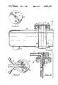
- FIGS. 7 through 10illustrate the connecting plug portion of the system which interconnects the disposable dispenser module of FIGS. 2 through 6 with the control system 15 and the pipe 35 of the system shown in FIG. 1.
- the cap 65FIG. 6
- the plug assembly shown in FIGS. 7 through 10then is placed on top of the neck 50 to provide the fluid withdrawal and electrical interconnections with the module 23 which are necessary to permit it to be used in the system shown in FIG. 1.
- the plug assembly 38which includes an upper housing member 67 with an outwardly extending flange (most clearly shown in FIGS. 8 and 9) around its bottom edge. This flange is dimensioned to overlie the top of the threaded neck 50 and is adapted to press firmly against the upper surface of the cap 55 permanently secured in the opening of the neck 50 as described previously.
- two electrically conductive pins 80 and 81are mounted in the member 67 and are securely held in place in it. These pins 80 and 81 extend beneath the flange 69 and are spaced apart to fit within the openings 58 and 59 to provide electrical interconnections between the pins 80 and 81 and the probes 62 and 63, respectively. This form of electrical connection is used extensively in a variety of different applications.
- the wires 36 and 37are attached to the tops of the pins 80 and 81 and are in electrical contact with the pins.
- a fluid withdrawal tube 71which may be made either of plastic or of metal, extends downwardly substantially near the center of the member 67, and an air admitting pipe 72 is provided through the member 67 immediately adjacent the withdrawal tube 71. This is shown most clearly in FIG. 8.
- the tube 71 and the air withdrawal pipe 72fit snugly within the correspondingly shaped opening 57 in the top of the cap 55.
- An elbow 70extends at 90° (degrees) from the top of the tube 71 (and may be integrally formed with the tube 71) for connection to the flexible withdrawal hose 35. This connection may be made in any suitable manner, such as a threaded connector or a force fit connection, depending upon the specific application desired.
- Sufficient lengthis provided in the wires 36 and 37 which extend from the control system 15 (FIG. 1) and the flexible hose 35 to permit the connections to be made to the member 67 in a manner allowing the plug to be moved into and out of the lavage machine through the door 40 at least to an extent sufficient to permit easy connection of the plug 67 with the cap 55 on the filler neck 50 of the disposable module 23 outside the lavage machine.
- an alternative arrangementuses only a single conductive probe 63.
- the pipe 71is made of metal and the wire 37 is connected to a metal spring clip 84 (FIG. 7) attached to the pipe 71. This is shown in dotted lines in FIG. 7.
- the pipe 71then serves the added function of the eliminated probe 62.
- the level sensing functionis otherwise exactly the same as described above for the two probe embodiments shown in solid lines.
- an open threaded ring 68is placed over the member 67 and overlies the top of the outwardly extending flange 69, as shown in FIG. 8.
- the cap 68is screwed onto the neck 50 (from which the throw-away cap 65 has been removed) to hold the cap 67 securely in place on the top of the module 23.
- the lower side of the flange 69is pressed tightly against the top surface of the cap 55, as described previously.
- fluidmay be withdrawn from the module 23 as required by the lavage machine of FIG. 1.
- the "add solution” light 32 on the control panelis turned on, as described previously. When this occurs, reversal of the process which is used to interconnect a new module into the system is used to disconnect the old module. A new one then is inserted and placed within the machine for subsequent use.
- the light 32typically is turned on when the amount of remaining solution in the module is enough to complete the current cycle of operation of the lavage machine.
Landscapes
- Physics & Mathematics (AREA)
- Thermal Sciences (AREA)
- Fluid Mechanics (AREA)
- General Physics & Mathematics (AREA)
- Engineering & Computer Science (AREA)
- Textile Engineering (AREA)
- Infusion, Injection, And Reservoir Apparatuses (AREA)
Abstract
Description
Claims (21)
Priority Applications (1)
| Application Number | Priority Date | Filing Date | Title |
|---|---|---|---|
| US07/217,303US4921129A (en) | 1988-07-11 | 1988-07-11 | Liquid dispensing module |
Applications Claiming Priority (1)
| Application Number | Priority Date | Filing Date | Title |
|---|---|---|---|
| US07/217,303US4921129A (en) | 1988-07-11 | 1988-07-11 | Liquid dispensing module |
Publications (1)
| Publication Number | Publication Date |
|---|---|
| US4921129Atrue US4921129A (en) | 1990-05-01 |
Family
ID=22810498
Family Applications (1)
| Application Number | Title | Priority Date | Filing Date |
|---|---|---|---|
| US07/217,303Expired - Fee RelatedUS4921129A (en) | 1988-07-11 | 1988-07-11 | Liquid dispensing module |
Country Status (1)
| Country | Link |
|---|---|
| US (1) | US4921129A (en) |
Cited By (26)
| Publication number | Priority date | Publication date | Assignee | Title |
|---|---|---|---|---|
| USD352578S (en) | 1990-07-09 | 1994-11-15 | Diversey Corporation | Dishwasher detergent dispenser |
| DE19726707C1 (en)* | 1997-06-24 | 1998-09-10 | Henkel Ecolab Gmbh & Co Ohg | Dispenser for dry cleaning liquids and auxiliaries |
| US6131601A (en)* | 1999-06-04 | 2000-10-17 | S. C. Johson Commercial Markets, Inc. | Fluid mixing apparatus |
| WO2002008509A1 (en)* | 2000-07-19 | 2002-01-31 | The Procter & Gamble Company | Detergent pack |
| US20050224596A1 (en)* | 2003-07-08 | 2005-10-13 | Panopoulos Peter J | Machine that is an automatic pesticide, insecticide, repellant, poison, air freshener, disinfectant or other type of spray delivery system |
| US20090272003A1 (en)* | 2008-05-01 | 2009-11-05 | Whirlpool Corporation | Failure mode detection in an appliance dispensing system |
| WO2011009777A1 (en)* | 2009-07-21 | 2011-01-27 | BSH Bosch und Siemens Hausgeräte GmbH | Water-bearing household appliance |
| WO2011009776A1 (en)* | 2009-07-21 | 2011-01-27 | BSH Bosch und Siemens Hausgeräte GmbH | Water-bearing household appliance |
| WO2011009774A1 (en)* | 2009-07-21 | 2011-01-27 | BSH Bosch und Siemens Hausgeräte GmbH | Water-conducting domestic appliance |
| EP2184529A3 (en)* | 2008-11-06 | 2012-02-08 | Telematics Wireless Ltd. | Retrofit apparatus and method for gas line moisture detection and removal |
| US20130001248A1 (en)* | 2010-11-23 | 2013-01-03 | Whirlpool Corporation | Non-integrated bulk dispenser and method of operating a dishwasher having same |
| EP2733249A3 (en)* | 2014-02-20 | 2014-08-06 | V-Zug AG | Washing machine with storage containers for detergents |
| US8950019B2 (en) | 2007-09-20 | 2015-02-10 | Bradley Fixtures Corporation | Lavatory system |
| US8997271B2 (en) | 2009-10-07 | 2015-04-07 | Bradley Corporation | Lavatory system with hand dryer |
| US9170148B2 (en) | 2011-04-18 | 2015-10-27 | Bradley Fixtures Corporation | Soap dispenser having fluid level sensor |
| US9267736B2 (en) | 2011-04-18 | 2016-02-23 | Bradley Fixtures Corporation | Hand dryer with point of ingress dependent air delay and filter sensor |
| WO2016094650A1 (en)* | 2014-12-10 | 2016-06-16 | The Procter & Gamble Company | Container for fabric treatment composition |
| US9758953B2 (en) | 2012-03-21 | 2017-09-12 | Bradley Fixtures Corporation | Basin and hand drying system |
| CN106319875B (en)* | 2015-07-04 | 2018-06-08 | 杭州神林电子有限公司 | A kind of detergent with detection function storage delivery device of roller washing machine |
| US9999340B2 (en) | 2010-11-23 | 2018-06-19 | Whirlpool Corporation | Dishwasher and dispensing assembly |
| US10041236B2 (en) | 2016-06-08 | 2018-08-07 | Bradley Corporation | Multi-function fixture for a lavatory system |
| US10100501B2 (en) | 2012-08-24 | 2018-10-16 | Bradley Fixtures Corporation | Multi-purpose hand washing station |
| CN109554894A (en)* | 2018-11-30 | 2019-04-02 | 余姚市朗硕电器科技有限公司 | Children's garment conditioning liquid release platform |
| US20200080247A1 (en)* | 2018-09-12 | 2020-03-12 | Haier Us Appliance Solutions, Inc. | Fluid sensor assembly for a washing machine appliance |
| US11015329B2 (en) | 2016-06-08 | 2021-05-25 | Bradley Corporation | Lavatory drain system |
| CN115627619A (en)* | 2021-05-20 | 2023-01-20 | 青岛海尔滚筒洗衣机有限公司 | Sealing cover structure of liquid storage box, feeding device and clothes treatment equipment |
Citations (15)
| Publication number | Priority date | Publication date | Assignee | Title |
|---|---|---|---|---|
| US2673007A (en)* | 1950-08-03 | 1954-03-23 | Debrie Andre Victor Le Clement | Removable pumping tank for automatic developing machines |
| US2965267A (en)* | 1958-06-26 | 1960-12-20 | Harold B Shapira | Liquid soap dispenser |
| US3459343A (en)* | 1967-08-24 | 1969-08-05 | Holger Rasmussen | Soap dispenser |
| US3465915A (en)* | 1966-08-11 | 1969-09-09 | Robert De Harde | Liquid metering and dispensing apparatus |
| US3836050A (en)* | 1973-04-20 | 1974-09-17 | Emerson Electric Co | Remote plastic dispensing head with fluid level actuated expansion chamber shut off |
| US3871560A (en)* | 1973-08-01 | 1975-03-18 | Prod Associes Sa | Reservoir for a liquid pump including means for initially forcing liquid into the pump |
| US4009598A (en)* | 1975-11-26 | 1977-03-01 | General Motors Corporation | Automatic treating agent dispenser for washing appliance |
| US4164306A (en)* | 1978-04-03 | 1979-08-14 | Towlsaver, Inc. | Soap dispenser including removable soap supply container positioner and stabilizer |
| US4186849A (en)* | 1978-04-04 | 1980-02-05 | Spangler Searle T | Control circuit for automatically monitoring, dispensing, and filling a liquid in a container |
| US4264019A (en)* | 1979-08-17 | 1981-04-28 | The Firestone Tire & Rubber Company | Beverage dispenser |
| CH631134A5 (en)* | 1978-09-04 | 1982-07-30 | Ciba Geigy Ag | Outflow fitting for a liquid container |
| US4345627A (en)* | 1980-01-21 | 1982-08-24 | Steiner Corporation | Soap dispensing system |
| US4391309A (en)* | 1981-04-16 | 1983-07-05 | Steiner Corporation | Soap dispensing system |
| US4489857A (en)* | 1982-03-22 | 1984-12-25 | Bobrick Washroom Equipment, Inc. | Liquid dispenser |
| US4714176A (en)* | 1985-01-24 | 1987-12-22 | Oce-Nederland B.V. | Liquid supply reservoir |
- 1988
- 1988-07-11USUS07/217,303patent/US4921129A/ennot_activeExpired - Fee Related
Patent Citations (15)
| Publication number | Priority date | Publication date | Assignee | Title |
|---|---|---|---|---|
| US2673007A (en)* | 1950-08-03 | 1954-03-23 | Debrie Andre Victor Le Clement | Removable pumping tank for automatic developing machines |
| US2965267A (en)* | 1958-06-26 | 1960-12-20 | Harold B Shapira | Liquid soap dispenser |
| US3465915A (en)* | 1966-08-11 | 1969-09-09 | Robert De Harde | Liquid metering and dispensing apparatus |
| US3459343A (en)* | 1967-08-24 | 1969-08-05 | Holger Rasmussen | Soap dispenser |
| US3836050A (en)* | 1973-04-20 | 1974-09-17 | Emerson Electric Co | Remote plastic dispensing head with fluid level actuated expansion chamber shut off |
| US3871560A (en)* | 1973-08-01 | 1975-03-18 | Prod Associes Sa | Reservoir for a liquid pump including means for initially forcing liquid into the pump |
| US4009598A (en)* | 1975-11-26 | 1977-03-01 | General Motors Corporation | Automatic treating agent dispenser for washing appliance |
| US4164306A (en)* | 1978-04-03 | 1979-08-14 | Towlsaver, Inc. | Soap dispenser including removable soap supply container positioner and stabilizer |
| US4186849A (en)* | 1978-04-04 | 1980-02-05 | Spangler Searle T | Control circuit for automatically monitoring, dispensing, and filling a liquid in a container |
| CH631134A5 (en)* | 1978-09-04 | 1982-07-30 | Ciba Geigy Ag | Outflow fitting for a liquid container |
| US4264019A (en)* | 1979-08-17 | 1981-04-28 | The Firestone Tire & Rubber Company | Beverage dispenser |
| US4345627A (en)* | 1980-01-21 | 1982-08-24 | Steiner Corporation | Soap dispensing system |
| US4391309A (en)* | 1981-04-16 | 1983-07-05 | Steiner Corporation | Soap dispensing system |
| US4489857A (en)* | 1982-03-22 | 1984-12-25 | Bobrick Washroom Equipment, Inc. | Liquid dispenser |
| US4714176A (en)* | 1985-01-24 | 1987-12-22 | Oce-Nederland B.V. | Liquid supply reservoir |
Cited By (38)
| Publication number | Priority date | Publication date | Assignee | Title |
|---|---|---|---|---|
| USD352578S (en) | 1990-07-09 | 1994-11-15 | Diversey Corporation | Dishwasher detergent dispenser |
| DE19726707C1 (en)* | 1997-06-24 | 1998-09-10 | Henkel Ecolab Gmbh & Co Ohg | Dispenser for dry cleaning liquids and auxiliaries |
| US6131601A (en)* | 1999-06-04 | 2000-10-17 | S. C. Johson Commercial Markets, Inc. | Fluid mixing apparatus |
| WO2002008509A1 (en)* | 2000-07-19 | 2002-01-31 | The Procter & Gamble Company | Detergent pack |
| US20050224596A1 (en)* | 2003-07-08 | 2005-10-13 | Panopoulos Peter J | Machine that is an automatic pesticide, insecticide, repellant, poison, air freshener, disinfectant or other type of spray delivery system |
| US8950019B2 (en) | 2007-09-20 | 2015-02-10 | Bradley Fixtures Corporation | Lavatory system |
| US20090272003A1 (en)* | 2008-05-01 | 2009-11-05 | Whirlpool Corporation | Failure mode detection in an appliance dispensing system |
| US8756828B2 (en) | 2008-05-01 | 2014-06-24 | Whirlpool Corporation | Failure mode detection in an appliance dispensing system |
| EP2184529A3 (en)* | 2008-11-06 | 2012-02-08 | Telematics Wireless Ltd. | Retrofit apparatus and method for gas line moisture detection and removal |
| CN102481085B (en)* | 2009-07-21 | 2014-08-20 | Bsh博世和西门子家用电器有限公司 | Water-bearing household appliance |
| CN102481085A (en)* | 2009-07-21 | 2012-05-30 | Bsh博世和西门子家用电器有限公司 | Water-containing domestic appliance |
| WO2011009774A1 (en)* | 2009-07-21 | 2011-01-27 | BSH Bosch und Siemens Hausgeräte GmbH | Water-conducting domestic appliance |
| EA021272B1 (en)* | 2009-07-21 | 2015-05-29 | Бсх Бош Унд Сименс Хаусгерете Гмбх | Water-bearing household appliance |
| WO2011009777A1 (en)* | 2009-07-21 | 2011-01-27 | BSH Bosch und Siemens Hausgeräte GmbH | Water-bearing household appliance |
| EA019576B1 (en)* | 2009-07-21 | 2014-04-30 | Бсх Бош Унд Сименс Хаусгерете Гмбх | Water-conducting domestic appliance |
| WO2011009776A1 (en)* | 2009-07-21 | 2011-01-27 | BSH Bosch und Siemens Hausgeräte GmbH | Water-bearing household appliance |
| US8997271B2 (en) | 2009-10-07 | 2015-04-07 | Bradley Corporation | Lavatory system with hand dryer |
| US20130001248A1 (en)* | 2010-11-23 | 2013-01-03 | Whirlpool Corporation | Non-integrated bulk dispenser and method of operating a dishwasher having same |
| US20140110430A1 (en)* | 2010-11-23 | 2014-04-24 | Whirlpool Corporation | Non-integrated bulk dispenser and method of operating a dishwasher having same |
| US8627984B2 (en)* | 2010-11-23 | 2014-01-14 | Whirlpool Corporation | Non-integrated bulk dispenser and method of operating a dishwasher having same |
| US9420935B2 (en)* | 2010-11-23 | 2016-08-23 | Whirlpool Corporation | Non-integrated bulk dispenser and method of operating a dishwasher having same |
| US10285563B2 (en) | 2010-11-23 | 2019-05-14 | Whirlpool Corporation | Non-integrated bulk dispenser and method of operating a dishwasher having same |
| US9999339B2 (en) | 2010-11-23 | 2018-06-19 | Whirlpool Corporation | Non-integrated bulk dispenser and method of operating a dishwasher having same |
| US9999340B2 (en) | 2010-11-23 | 2018-06-19 | Whirlpool Corporation | Dishwasher and dispensing assembly |
| US9170148B2 (en) | 2011-04-18 | 2015-10-27 | Bradley Fixtures Corporation | Soap dispenser having fluid level sensor |
| US9267736B2 (en) | 2011-04-18 | 2016-02-23 | Bradley Fixtures Corporation | Hand dryer with point of ingress dependent air delay and filter sensor |
| US9441885B2 (en) | 2011-04-18 | 2016-09-13 | Bradley Fixtures Corporation | Lavatory with dual plenum hand dryer |
| US9758953B2 (en) | 2012-03-21 | 2017-09-12 | Bradley Fixtures Corporation | Basin and hand drying system |
| US10100501B2 (en) | 2012-08-24 | 2018-10-16 | Bradley Fixtures Corporation | Multi-purpose hand washing station |
| EP2733249A3 (en)* | 2014-02-20 | 2014-08-06 | V-Zug AG | Washing machine with storage containers for detergents |
| WO2016094650A1 (en)* | 2014-12-10 | 2016-06-16 | The Procter & Gamble Company | Container for fabric treatment composition |
| CN106319875B (en)* | 2015-07-04 | 2018-06-08 | 杭州神林电子有限公司 | A kind of detergent with detection function storage delivery device of roller washing machine |
| US10041236B2 (en) | 2016-06-08 | 2018-08-07 | Bradley Corporation | Multi-function fixture for a lavatory system |
| US11015329B2 (en) | 2016-06-08 | 2021-05-25 | Bradley Corporation | Lavatory drain system |
| US20200080247A1 (en)* | 2018-09-12 | 2020-03-12 | Haier Us Appliance Solutions, Inc. | Fluid sensor assembly for a washing machine appliance |
| US10914029B2 (en)* | 2018-09-12 | 2021-02-09 | Haier Us Appliance Solutions, Inc. | Fluid sensor assembly for a washing machine appliance |
| CN109554894A (en)* | 2018-11-30 | 2019-04-02 | 余姚市朗硕电器科技有限公司 | Children's garment conditioning liquid release platform |
| CN115627619A (en)* | 2021-05-20 | 2023-01-20 | 青岛海尔滚筒洗衣机有限公司 | Sealing cover structure of liquid storage box, feeding device and clothes treatment equipment |
Similar Documents
| Publication | Publication Date | Title |
|---|---|---|
| US4921129A (en) | Liquid dispensing module | |
| US6006388A (en) | Dispenser for dispensing concentrated liquid soap to industrial cleaning apparatuses | |
| US6138693A (en) | Automatic detergent dispenser | |
| EP0551254B1 (en) | Chemical solution dispensing and handling system | |
| US5056685A (en) | Spraying device | |
| US6039219A (en) | Liquid dispensing system for a refrigerator | |
| CA2487816C (en) | Automated cleansing sprayer | |
| CA2125160C (en) | Dispenser of doses of liquid soap or the like | |
| US20080078780A1 (en) | Automatic dispenser | |
| MXPA97002302A (en) | Quim solution filling system | |
| CA2397073A1 (en) | Device for dispensing soap-solution in a dispenser | |
| US4830509A (en) | Automatic system for dissolving dry detergent | |
| GB2194258A (en) | Lavatory cleansing device | |
| CA2295774A1 (en) | Compact liquid dosing apparatus with a reservoir | |
| KR101949327B1 (en) | A faucet capable of automatic discharge of water and detergent | |
| US5184476A (en) | Counter-height water dispenser | |
| US4749107A (en) | Beverage reservoir with overflow passageway in the handle | |
| US4732297A (en) | Liquid level detector apparatus for a concentrate dispenser tank | |
| US2910075A (en) | Pressurized device for injecting drying agent into rinse spray system | |
| AU725338B2 (en) | Dual-chamber canister for producing diluted ready-to-use solutions with anti-confusion protection | |
| GB2306303A (en) | Detergent dispenser | |
| CA1116131A (en) | Dispensing device for windshield washer liquid | |
| EP0636103B1 (en) | Coupling for connecting conduits in an automatic device for distributing a food product and connection pieces thereof | |
| GB2049623A (en) | Improvements in or Relating to Dispensing Machines | |
| JPH0354218Y2 (en) |
Legal Events
| Date | Code | Title | Description |
|---|---|---|---|
| AS | Assignment | Owner name:PACIFIC BIOSYSTEMS, INC., A CORP. OF ARIZONA Free format text:ASSIGNMENT OF ASSIGNORS INTEREST.;ASSIGNORS:JONES, K. TOM;CALDWELL, RICHARD J.;REEL/FRAME:004907/0507 Effective date:19880622 Owner name:PACIFIC BIOSYSTEMS, INC.,ARIZONA Free format text:ASSIGNMENT OF ASSIGNORS INTEREST;ASSIGNORS:JONES, K. TOM;CALDWELL, RICHARD J.;REEL/FRAME:004907/0507 Effective date:19880622 | |
| REMI | Maintenance fee reminder mailed | ||
| LAPS | Lapse for failure to pay maintenance fees | ||
| FP | Lapsed due to failure to pay maintenance fee | Effective date:19940501 | |
| AS | Assignment | Owner name:LEMBERG, DANNY, NEW YORK Free format text:ASSIGNMENT OF ASSIGNORS INTEREST;ASSIGNOR:ABELE, ROBERT PATRICK, TRUSTEE FOR BANKRUPTCY ESTATE OF PACIFIC BIOSYSTEMS, INC.;REEL/FRAME:007132/0813 Effective date:19940826 Owner name:CARL, SHELBY A., ARIZONA Free format text:ASSIGNMENT OF ASSIGNORS INTEREST;ASSIGNOR:ABELE, ROBERT PATRICK, TRUSTEE FOR BANKRUPTCY ESTATE OF PACIFIC BIOSYSTEMS, INC.;REEL/FRAME:007132/0813 Effective date:19940826 | |
| STCH | Information on status: patent discontinuation | Free format text:PATENT EXPIRED DUE TO NONPAYMENT OF MAINTENANCE FEES UNDER 37 CFR 1.362 |