US4920381A - Toner container lift mechanism - Google Patents
Toner container lift mechanismDownload PDFInfo
- Publication number
- US4920381A US4920381AUS07/293,033US29303389AUS4920381AUS 4920381 AUS4920381 AUS 4920381AUS 29303389 AUS29303389 AUS 29303389AUS 4920381 AUS4920381 AUS 4920381A
- Authority
- US
- United States
- Prior art keywords
- toner
- container
- cam
- spring
- cams
- Prior art date
- Legal status (The legal status is an assumption and is not a legal conclusion. Google has not performed a legal analysis and makes no representation as to the accuracy of the status listed.)
- Expired - Lifetime
Links
Images
Classifications
- G—PHYSICS
- G03—PHOTOGRAPHY; CINEMATOGRAPHY; ANALOGOUS TECHNIQUES USING WAVES OTHER THAN OPTICAL WAVES; ELECTROGRAPHY; HOLOGRAPHY
- G03G—ELECTROGRAPHY; ELECTROPHOTOGRAPHY; MAGNETOGRAPHY
- G03G15/00—Apparatus for electrographic processes using a charge pattern
- G03G15/06—Apparatus for electrographic processes using a charge pattern for developing
- G03G15/08—Apparatus for electrographic processes using a charge pattern for developing using a solid developer, e.g. powder developer
- G03G15/0822—Arrangements for preparing, mixing, supplying or dispensing developer
- G—PHYSICS
- G03—PHOTOGRAPHY; CINEMATOGRAPHY; ANALOGOUS TECHNIQUES USING WAVES OTHER THAN OPTICAL WAVES; ELECTROGRAPHY; HOLOGRAPHY
- G03G—ELECTROGRAPHY; ELECTROPHOTOGRAPHY; MAGNETOGRAPHY
- G03G15/00—Apparatus for electrographic processes using a charge pattern
- G03G15/06—Apparatus for electrographic processes using a charge pattern for developing
- G03G15/08—Apparatus for electrographic processes using a charge pattern for developing using a solid developer, e.g. powder developer
- G03G15/0896—Arrangements or disposition of the complete developer unit or parts thereof not provided for by groups G03G15/08 - G03G15/0894
Definitions
- This inventionrelates to apparatus in an electrostatographic copier or printer for developing electrostatic images with toner, and more particularly to a mechanism in a space restricted development apparatus for automatically and gradually lifting a toner container in order to maintain contact between toner in the container and means, including a replenishment roller, for transferring the toner to the electrostatic images.
- electrostatic images, on an insulated image bearing member, such as a photoconductorare developed, that is, made visible with toner particles.
- a development apparatustypically includes a development roller, a toner replenishment roller, and a container for holding the toner particles.
- the development rollerwhich rotates about a fixed axis, and spaced from the image bearing member, functions to carry and bring toner particles into transfer contact with electrostatic images on the image bearing member.
- the toner particleswhich are precharged, triboelectrically, for example, are supplied to the development roller by the toner replenishment roller.
- the toner replenishment rollerrotates about a fixed axis, and is in contact with the development roller. -n addition, the replenishment roller must also rotate in contact with the toner particles being held in the container or sump portion of the development apparatus.
- the development apparatus of an electrostatographic copier or printerincludes a cam and spring assembly for supporting, and for automatically lifting and lowering a toner container in response to changes in the weight of toner in the container.
- the cam and spring assemblyincludes a pivotable cam with at least one flat side, as well as, a horizontal spring that is connected to the cam. The spring operates to resist the pivoting movement of the cam, as well as, to return the cam after it has moved in response to changes in the quantity of toner in the container.
- cam and spring assembly mechanism of the present inventionis suitable for use in height restricted environments. It is simple and inexpensive, and it substantially maintains a constant lifting force on the toner container throughout the lift distance. Other aspects and advantages of the mechanism of the present invention will become more apparent from the following drawing and detailed description.
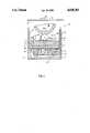
- the figureis a side sectional view of part of a development apparatus in an electrostatographic copier or printer including the cam and spring assembly lift mechanism of the present invention.
- the development apparatus 20For developing electrostatic images 12 on an image bearing member 10 being moved, for example, in the direction of the arrow 18, in an electrostatographic copier or printer.
- the development apparatus 20includes a housing 22 that may be fixed to the support frame of the copier or printer.
- the housing 22has a base 24, side walls 26, 28, and a back wall (not shown).
- housing 22may have an open front end for providing front access into the housing.
- a container 32which has a base 34 and side walls 36, 38, is located and adapted to move up and down on the side walls 26, 28 of the housing.
- the container 32which also includes end walls (not shown), is suitable for holding toner particles 40, and can be moved so that its bottom 34 goes from a lowered position along the line B--B, to a fully raised position, for example, along the line C--C.
- the tonerWhen the container 32 is full of toner, the toner will occupy it, for example, to a level F.
- the level Fis chosen so as to maximize the quantity of toner 40 that the container 32 can hold. Since the housing 22 includes an open front end, the container 32 may come in the form of a cartridge, prefilled with toner to the level F, and ready for front to back loading into the housing 22.
- Development apparatus 20further includes a development roller 42 that is rotatable about a fixed axis in the direction of the arrow 42A, for example.
- Development roller 42which rotates as such, and is spaced from the image bearing member 10, includes a series of magnets on its periphery for carrying and bringing charged toner into transfer contact with the electrostatic latent images 12 on the image bearing member 10.
- the charged toner 40is supplied to the development roller 42 by a toner replenishment roller 44.
- Roller 44which may include brush type bristles for carrying the toner, rotates about a fixed axis in the direction of the arrow 44A, as well as, in contact with the development roller 42. In addition, roller 44 must also rotate in contact with the toner 40 within the container 32.
- Rotation of the roller 44will contact and carry toner from the container into transfer contact with the development roller 42.
- the roller 42in turn will carry the toner into transfer contact with electrostatic latent images on the image bearing member 10, where the toner is attracted and held making the electrostatic images visible.
- Such transfer of tonerdepletes the quantity of toner within the container 32, therefore tending to cause the level of toner remaining in the container to drop below, and out of contact with the roller 44.
- the roller 44since the roller 44 rotates about a fixed axis, the container 32 must be moved upwards towards the roller 44 in order to maintain the desired transfer contact between the roller 44 and the depleting level of toner within the container 32.
- Development apparatus 20therefore includes a mechanism, generally designated 50, for supporting, and for automatically lifting and lowering the container 32 in order to maintain the desired transfer contact with the replenishment roller 44.
- the mechanism 50as shown, is located in the housing 22 underneath the container 32, within a restricted space shown as having a height AB.
- the height ABis made as minimal as possible in order to maximize the distance BD between mechanism 50 and roller 44, and hence to maximize the quantity of toner 40 in a full container 32.
- the mechanism 50must be such that when the container 32 is filled with toner 40 to the level F, the mechanism 50 will support the bottom of the container 32 in its lowered position along B--B such that the toner at the level F just makes contact with the roller 44.
- the mechanism 50consists essentially of a cam and spring assembly, in which a pair of cams 51, 53, are connected by a spring 55.
- the cams 51, 53which can be made inexpensively from a plastic material, are supported pivotably about fixed axes P1, P2, respectively. Axes P1, P2 are spaced and centered between the walls 26, 28.
- the means of such axial supportfor example a shaft, must be strong enough to enable the cams to safely support the weight of the container 32 when it is full of toner.
- each cam 51, 53has at least one flat side 56, 58, respectively.
- cam 51As supported about the axis P1, cam 51, for example, is capable of resting at a lowered position along the line B--B In this lowered position, the flat side 56 of cam 51, is essentially horizontal to the line B--B, and can fully contact and support the flat bottom 34 of the container 32. From the position along B--B, the cam 51 can be pivoted upwards, and variably about P1, until the distal end 61 of the flat side 56 reaches or is close to a fully raised position along the line C--C.
- the flat side 56is preferably short of the vertical V1 in order to insure that the cam 51, if loaded at the distal end 61 of such flat side, will reverse its pivotal movement, rather than continue its upwards pivotal movement.
- the cam 53 as supported about the axis, P2exactly mirrors the operation of cam 51 with respect to its pivoting movements between a lowered position along the line B--B (shown in phantom) to a raised position along the line C--C.
- each cam 51, 53can be L-shaped, thereby consisting of first portions 60, 66 and second portions 62, 64, respectively such that, as clearly shown in the drawing, the first portion of each cam is longer than its second portion.
- each first and second portionsare connected at an elbow through, and along which run the axes P1, P2.
- the outside surfaces of the first portions 60, 66form the flat sides 56, 58.
- the spring 55is connected to each cam 51, 53 at a fixed point that is below the pivot and support axes P1, P2, and preferably diagonally across from the distal end of each flat side 56, 58. As shown, such connection can be suitably made at the distal ends of the second portions 62, 64 of the L-shaped cams. When a pair of cams is utilized, as shown, the cams are connected to each other by the spring 55.
- a single camcan be employed in which case the spring 55 will be connected to the cam as described, and then to an appropriate point on side wall 26 or 28.
- the spring 55which may be a cylindrical helical spring of circular cross-section, can be made of stainless steel wire. Because of buckling problems associated with unsupported compression springs, spring 55 is preferably an unsupported tension spring, and its free length should be such that the spring, when connected as described above, experiences zero deflection with the cam or cams in their fully raised positions along the line C--C. For example, the spring 55 will have zero deflection when the second portions 62, 64 of the cams 51, 53, are pulled toward each other, while the first portions 60, 66 are in their fully raised positions along C--C.
- the spring 55should be made so as to have an available deflection sufficient to enable the first portions 60, 66 of the cams 51, 53 to be lowered pivotably from their fully raised positions along C--C, down to their lowered and horizontal positions along the line B--B.
- spring 55should be made so that its load characteristics are such that the weight of the container 32, when filled with toner 40 to the level F, is sufficient to fully load and fully deflect the spring 55. Filling the container 32 to the level F with toner, should therefore lower the distal ends 61, 63 of the flat sides 56, 58, from their fully raised positions along C--C, to their lowered, horizontal positions along B--B while loading and fully deflecting the spring 55 in the process.
- spring 55of course will act to exert constant inward forces, for example, on the second portions 62, 64 of the cams 51, 53, respectively.
- inward forcesresult in a pivoting tendency of the cams 51, 53, about the axes P1, P2, and hence also in a pivoting tendency of the first portions 60, 66, upwards.
- the portions 60, 66therefore push upwardly against the weight of toner in the container 32.
- the load characteristics of the spring 55should also be such that this upward pushing imparted to the portions 60, 66, is just equal to the weight of toner in the container 32, when the portions 60, 66 are in their lowered positions along B--B.
- the load characteristics of the spring 55for example, the spring rate, should be such that, as the quantity of toner in the container 32 is depleted over time by continued transfer to electrostatic latent images on the member 10, the upward pushing imparted to the portions 60, 66 remains constant, and therefore proportionally becomes greater and greater than the weight of the remaining quantity of toner in the container.
- the resultis a constant, gradual and proportional lifting of the container 32 in direct response to the degree of depletion or reduction of the quantity of toner in the container.
- the lifting force imparted to the portions 60, 66becomes greater than the weight of the depleting toner in the container 32, the force on the container is constant because the lifting force acts at a fixed point relative to the pivot points P1, P2, but the decreasing weight of toner gradually acts effectively at an increasing distance from the pivots P1, P2.
- the momentums created about the pivots P1, P2are equalized gradually as the point of contact between the bottom of the container 32 and the portions 60, 66 move away from pivot points P1, P2 towards the distal ends 61, 63 of the flat sides 56, 58.
- the container 32When the container 32 is so depleted of toner such that the portions 60, 66 are at their fully raised positions, the container 32 (now essentially empty) can be refilled with precharged toner from a refill source, such as a toner bottle. As such new toner is being added to the container 32, the additional weight of toner pushes down on the portions 60, 66, counteracting their upwardly pushing forces, and thereby loading the spring 55 toward full deflection. A quantity of toner sufficient to refill the container 32 to the level F, can be added. Doing so should automatically lower the portions 60, 66 to their lowered positions along B--B while fully deflecting the spring 55.
- a refill sourcesuch as a toner bottle.
- each first portion 60, 66is preferably rounded so as to provide a rotatable surface for contact with the bottom 34, when such contact finally shifts to that area of the flat side 56, 58.
- One advantage of this shifting of the contact pointis that there is substantially no change in the force pushing the toner in the container against the roller 44, as the portions 60, 66 pivot from B--B to C--C.
- the spring 55should be selected so that the given travel of the toner container from B--B to C--C is achieved with a minimal deflection of the spring, for example, a deflection that is only about 10 percent of the free length of the spring.
- a single camcan also be employed.
- the single camfor example, can be identical to cam 51. It also can be made out of a plastic material, but it will be located such that, lowered or raised, it will tend to contact and support the center of the bottom 34 of the container 32.
- the tension spring 55will be connected, for example, to the second portion 62, and then to the opposite wall 28 of the housing 22. When so connected, such a single cam will operate to lift and lower the container 32 between the levels B--B and C--C in much the same way as the pair of cams 51, 53, responding, of course, to the depletion and addition of toner in the container 32.
- the mechanism of the present inventionis simple, low cost and less expensive than mechanisms employing bellows or pressurized air. Because it employs a horizontal tension spring, it is particularly suitable for use in height restricted spaces, and is not subject to buckling failure.
- the flat side, for example 56 of the cam 51has a profile which causes the contact point between the cam 51 and toner container 32 to move away from the pivot point P1 as the weight of toner in the container decreases, results in a gradual and desirably constant force pushing the toner in the container 32 against the replenishment roller 44.
Landscapes
- Physics & Mathematics (AREA)
- General Physics & Mathematics (AREA)
- Dry Development In Electrophotography (AREA)
Abstract
Description
Claims (10)
Priority Applications (1)
| Application Number | Priority Date | Filing Date | Title |
|---|---|---|---|
| US07/293,033US4920381A (en) | 1989-01-03 | 1989-01-03 | Toner container lift mechanism |
Applications Claiming Priority (1)
| Application Number | Priority Date | Filing Date | Title |
|---|---|---|---|
| US07/293,033US4920381A (en) | 1989-01-03 | 1989-01-03 | Toner container lift mechanism |
Publications (1)
| Publication Number | Publication Date |
|---|---|
| US4920381Atrue US4920381A (en) | 1990-04-24 |
Family
ID=23127344
Family Applications (1)
| Application Number | Title | Priority Date | Filing Date |
|---|---|---|---|
| US07/293,033Expired - LifetimeUS4920381A (en) | 1989-01-03 | 1989-01-03 | Toner container lift mechanism |
Country Status (1)
| Country | Link |
|---|---|
| US (1) | US4920381A (en) |
Cited By (15)
| Publication number | Priority date | Publication date | Assignee | Title |
|---|---|---|---|---|
| US5132732A (en)* | 1991-01-22 | 1992-07-21 | Eastman Kodak Company | Dual axis displacement lifting mechanism for a development apparatus |
| US5148223A (en)* | 1990-11-16 | 1992-09-15 | Xerox Corporation | Developer dispenser having a developer mover for transporting developer |
| US5426492A (en)* | 1994-04-11 | 1995-06-20 | Xerox Corporation | Space optimizing toner cartridge |
| US5864731A (en)* | 1996-01-09 | 1999-01-26 | Canon Kabushiki Kaisa | Process cartridge, development apparatus, and electrophotographic image formation apparatus with plural toner feeding members |
| US20040035989A1 (en)* | 2002-08-21 | 2004-02-26 | Sweere Harry C. | Stand |
| US20040250635A1 (en)* | 2003-05-20 | 2004-12-16 | Sweere Harry C. | Lift mechanism based on torque equalization principles |
| US20050034547A1 (en)* | 2003-08-01 | 2005-02-17 | Sweere Harry C. | Mechanisms based on torque equalization principles |
| US20050139734A1 (en)* | 2000-11-28 | 2005-06-30 | Constant Force Technology, Llc | Monitor support system |
| US20050145762A1 (en)* | 2000-11-28 | 2005-07-07 | Constant Force Technology, Llc | Methods and apparatus for generating force and torque |
| US20060159472A1 (en)* | 2005-01-14 | 2006-07-20 | Konica Minolta Business Technologies, Inc. | Image forming apparatus |
| US7252277B2 (en) | 2003-01-17 | 2007-08-07 | Ergotron, Inc. | Support arm |
| US20080026892A1 (en)* | 2006-07-26 | 2008-01-31 | Ergotron, Inc. | Balanced moment lift system and method |
| US20100176254A1 (en)* | 2003-05-20 | 2010-07-15 | Ergotron, Inc. | Lift mechanism systems and methods |
| US8925154B2 (en) | 2003-05-20 | 2015-01-06 | Ergotron, Inc. | Pivot mechanism for adjusting a position of an electronic display |
| US9222616B2 (en) | 2012-03-30 | 2015-12-29 | Ergotron, Inc. | Counterbalancing lift mechanisms and methods |
Citations (7)
| Publication number | Priority date | Publication date | Assignee | Title |
|---|---|---|---|---|
| US3539077A (en)* | 1968-05-01 | 1970-11-10 | Eastman Kodak Co | Container and dispensing mechanism |
| US3914460A (en)* | 1973-01-09 | 1975-10-21 | Xerox Corp | Development utilizing electric fields |
| US4353637A (en)* | 1981-08-31 | 1982-10-12 | Xerox Corporation | Development system |
| US4417802A (en)* | 1981-11-19 | 1983-11-29 | Xerox Corporation | Particle dispenser |
| US4500196A (en)* | 1981-08-19 | 1985-02-19 | Ricoh Company, Ltd. | Photoconductive element cleaning apparatus and residual toner collecting apparatus |
| US4743937A (en)* | 1983-12-12 | 1988-05-10 | Xerox Corporation | Apparatus for charging toner particles |
| JPS63137260A (en)* | 1986-11-28 | 1988-06-09 | Mita Ind Co Ltd | Developer replacing device used in copying machine or the like |
- 1989
- 1989-01-03USUS07/293,033patent/US4920381A/ennot_activeExpired - Lifetime
Patent Citations (7)
| Publication number | Priority date | Publication date | Assignee | Title |
|---|---|---|---|---|
| US3539077A (en)* | 1968-05-01 | 1970-11-10 | Eastman Kodak Co | Container and dispensing mechanism |
| US3914460A (en)* | 1973-01-09 | 1975-10-21 | Xerox Corp | Development utilizing electric fields |
| US4500196A (en)* | 1981-08-19 | 1985-02-19 | Ricoh Company, Ltd. | Photoconductive element cleaning apparatus and residual toner collecting apparatus |
| US4353637A (en)* | 1981-08-31 | 1982-10-12 | Xerox Corporation | Development system |
| US4417802A (en)* | 1981-11-19 | 1983-11-29 | Xerox Corporation | Particle dispenser |
| US4743937A (en)* | 1983-12-12 | 1988-05-10 | Xerox Corporation | Apparatus for charging toner particles |
| JPS63137260A (en)* | 1986-11-28 | 1988-06-09 | Mita Ind Co Ltd | Developer replacing device used in copying machine or the like |
Cited By (28)
| Publication number | Priority date | Publication date | Assignee | Title |
|---|---|---|---|---|
| US5148223A (en)* | 1990-11-16 | 1992-09-15 | Xerox Corporation | Developer dispenser having a developer mover for transporting developer |
| WO1992013298A1 (en)* | 1991-01-22 | 1992-08-06 | Eastman Kodak Company | Dual axis displacement lifting mechanism for a development apparatus |
| US5132732A (en)* | 1991-01-22 | 1992-07-21 | Eastman Kodak Company | Dual axis displacement lifting mechanism for a development apparatus |
| US5426492A (en)* | 1994-04-11 | 1995-06-20 | Xerox Corporation | Space optimizing toner cartridge |
| US5864731A (en)* | 1996-01-09 | 1999-01-26 | Canon Kabushiki Kaisa | Process cartridge, development apparatus, and electrophotographic image formation apparatus with plural toner feeding members |
| US6994306B1 (en) | 2000-11-28 | 2006-02-07 | Constant Force Technology, Llc | Monitor support system |
| US7506853B2 (en) | 2000-11-28 | 2009-03-24 | Ergotron, Inc. | Methods and apparatus for generating force and torque |
| US7032870B2 (en) | 2000-11-28 | 2006-04-25 | Ergotron, Inc. | Methods and apparatus for generating force and torque |
| US20050139734A1 (en)* | 2000-11-28 | 2005-06-30 | Constant Force Technology, Llc | Monitor support system |
| US20050145762A1 (en)* | 2000-11-28 | 2005-07-07 | Constant Force Technology, Llc | Methods and apparatus for generating force and torque |
| US20040035989A1 (en)* | 2002-08-21 | 2004-02-26 | Sweere Harry C. | Stand |
| US6997422B2 (en) | 2002-08-21 | 2006-02-14 | Ergotron, Inc. | Stand |
| US7252277B2 (en) | 2003-01-17 | 2007-08-07 | Ergotron, Inc. | Support arm |
| US20040250635A1 (en)* | 2003-05-20 | 2004-12-16 | Sweere Harry C. | Lift mechanism based on torque equalization principles |
| US10267451B2 (en) | 2003-05-20 | 2019-04-23 | Ergotron, Inc. | Lift mechanism systems and methods |
| US9687073B2 (en) | 2003-05-20 | 2017-06-27 | Ergotron, Inc. | Lift mechanism systems and methods |
| US9360152B2 (en) | 2003-05-20 | 2016-06-07 | Ergotron, Inc. | Lift mechanism systems and methods |
| US8925154B2 (en) | 2003-05-20 | 2015-01-06 | Ergotron, Inc. | Pivot mechanism for adjusting a position of an electronic display |
| US20100176254A1 (en)* | 2003-05-20 | 2010-07-15 | Ergotron, Inc. | Lift mechanism systems and methods |
| US20100193653A1 (en)* | 2003-05-20 | 2010-08-05 | Ergotron, Inc. | Lift mechanism systems and methods |
| US9267639B2 (en) | 2003-05-20 | 2016-02-23 | Ergotron, Inc | Lift mechanism systems and methods |
| US8286927B2 (en) | 2003-05-20 | 2012-10-16 | Ergotron, Inc. | Lift mechanism systems and methods |
| US20050034547A1 (en)* | 2003-08-01 | 2005-02-17 | Sweere Harry C. | Mechanisms based on torque equalization principles |
| US7224914B2 (en)* | 2005-01-14 | 2007-05-29 | Konica Minolta Business Technologies, Inc. | Image forming apparatus having a movable toner container |
| US20060159472A1 (en)* | 2005-01-14 | 2006-07-20 | Konica Minolta Business Technologies, Inc. | Image forming apparatus |
| US8228668B2 (en) | 2006-07-26 | 2012-07-24 | Ergotron, Inc. | Balanced moment lift system and method |
| US20080026892A1 (en)* | 2006-07-26 | 2008-01-31 | Ergotron, Inc. | Balanced moment lift system and method |
| US9222616B2 (en) | 2012-03-30 | 2015-12-29 | Ergotron, Inc. | Counterbalancing lift mechanisms and methods |
Similar Documents
| Publication | Publication Date | Title |
|---|---|---|
| US4920381A (en) | Toner container lift mechanism | |
| US4435065A (en) | Electrographic developing apparatus with toner flow director | |
| US4943830A (en) | Developer dispensing apparatus with a spring element hold down shoe mechanism | |
| US4339196A (en) | Eccentric cam for electrophotocopier developer unit | |
| US20120263493A1 (en) | Image Forming Device | |
| CN104570641B (en) | Storing apparatus and image forming apparatus | |
| US7647011B2 (en) | Toner container and image forming apparatus provided with toner container | |
| JPH05219308A (en) | Image forming device | |
| JPS5824786B2 (en) | Toner level control | |
| US5893007A (en) | Combination development unit and toner level detection service | |
| EP0808719B1 (en) | Image forming device with variable paper feeding capacity | |
| US5215299A (en) | Spring elevator system for paper supply | |
| EP0521140A1 (en) | Dual axis displacement lifting mechanism for a development apparatus. | |
| US5401014A (en) | Sheet feeder for an image forming apparatus | |
| US3896279A (en) | Toner level detector assembly including magnetically responsive switch actuated by differential loaded blade type rotor carrying magnetic actuator | |
| KR970002513A (en) | Developing apparatus for an electrophotographic processor | |
| GB2255330A (en) | Sheet feed cassette. | |
| JPH0326836B2 (en) | ||
| JPS5952832B2 (en) | Toner supply device | |
| JP3245497B2 (en) | Developing device | |
| JPS5822224A (en) | seat cassette | |
| US3679099A (en) | Balance type toner concentration sensing and monitoring system | |
| JP2002123077A (en) | Toner supply device | |
| US3250439A (en) | Xerographic toner dispenser | |
| US4470474A (en) | Low range automatic weighing device |
Legal Events
| Date | Code | Title | Description |
|---|---|---|---|
| AS | Assignment | Owner name:EASTMAN KODAK COMPANY, A NEW JERSEY CORP., NEW YOR Free format text:ASSIGNMENT OF ASSIGNORS INTEREST.;ASSIGNOR:MAHONEY, GREGORY P.;REEL/FRAME:005009/0627 Effective date:19881229 | |
| FEPP | Fee payment procedure | Free format text:PAYOR NUMBER ASSIGNED (ORIGINAL EVENT CODE: ASPN); ENTITY STATUS OF PATENT OWNER: LARGE ENTITY | |
| STCF | Information on status: patent grant | Free format text:PATENTED CASE | |
| FPAY | Fee payment | Year of fee payment:4 | |
| FEPP | Fee payment procedure | Free format text:PAYER NUMBER DE-ASSIGNED (ORIGINAL EVENT CODE: RMPN); ENTITY STATUS OF PATENT OWNER: LARGE ENTITY Free format text:PAYOR NUMBER ASSIGNED (ORIGINAL EVENT CODE: ASPN); ENTITY STATUS OF PATENT OWNER: LARGE ENTITY | |
| FPAY | Fee payment | Year of fee payment:8 | |
| FEPP | Fee payment procedure | Free format text:PAYOR NUMBER ASSIGNED (ORIGINAL EVENT CODE: ASPN); ENTITY STATUS OF PATENT OWNER: LARGE ENTITY Free format text:PAYER NUMBER DE-ASSIGNED (ORIGINAL EVENT CODE: RMPN); ENTITY STATUS OF PATENT OWNER: LARGE ENTITY | |
| AS | Assignment | Owner name:NEXPRESS SOLUTIONS LLC, NEW YORK Free format text:ASSIGNMENT OF ASSIGNORS INTEREST;ASSIGNOR:EASTMAN KODAK COMPANY;REEL/FRAME:012036/0959 Effective date:20000717 | |
| FPAY | Fee payment | Year of fee payment:12 | |
| FEPP | Fee payment procedure | Free format text:PAYER NUMBER DE-ASSIGNED (ORIGINAL EVENT CODE: RMPN); ENTITY STATUS OF PATENT OWNER: LARGE ENTITY Free format text:PAYOR NUMBER ASSIGNED (ORIGINAL EVENT CODE: ASPN); ENTITY STATUS OF PATENT OWNER: LARGE ENTITY | |
| AS | Assignment | Owner name:EASTMAN KODAK COMPANY, NEW YORK Free format text:ASSIGNMENT OF ASSIGNORS INTEREST;ASSIGNOR:NEXPRESS SOLUTIONS, INC. (FORMERLY NEXPRESS SOLUTIONS LLC);REEL/FRAME:015928/0176 Effective date:20040909 |