US4920295A - Alternator - Google Patents
AlternatorDownload PDFInfo
- Publication number
- US4920295A US4920295AUS07/230,534US23053488AUS4920295AUS 4920295 AUS4920295 AUS 4920295AUS 23053488 AUS23053488 AUS 23053488AUS 4920295 AUS4920295 AUS 4920295A
- Authority
- US
- United States
- Prior art keywords
- shaft
- rotor
- stator
- alternator
- arms
- Prior art date
- Legal status (The legal status is an assumption and is not a legal conclusion. Google has not performed a legal analysis and makes no representation as to the accuracy of the status listed.)
- Expired - Fee Related
Links
Images

Classifications
- H—ELECTRICITY
- H02—GENERATION; CONVERSION OR DISTRIBUTION OF ELECTRIC POWER
- H02K—DYNAMO-ELECTRIC MACHINES
- H02K21/00—Synchronous motors having permanent magnets; Synchronous generators having permanent magnets
- H02K21/02—Details
- H02K21/021—Means for mechanical adjustment of the excitation flux
- H02K21/022—Means for mechanical adjustment of the excitation flux by modifying the relative position between field and armature, e.g. between rotor and stator
- H02K21/025—Means for mechanical adjustment of the excitation flux by modifying the relative position between field and armature, e.g. between rotor and stator by varying the thickness of the air gap between field and armature
- H02K21/027—Conical air gap machines
- H—ELECTRICITY
- H02—GENERATION; CONVERSION OR DISTRIBUTION OF ELECTRIC POWER
- H02K—DYNAMO-ELECTRIC MACHINES
- H02K21/00—Synchronous motors having permanent magnets; Synchronous generators having permanent magnets
- H02K21/12—Synchronous motors having permanent magnets; Synchronous generators having permanent magnets with stationary armatures and rotating magnets
- H02K21/14—Synchronous motors having permanent magnets; Synchronous generators having permanent magnets with stationary armatures and rotating magnets with magnets rotating within the armatures
Definitions
- the inventionis for an alternator or synchronous generator, principally for supplying electrical current to batteries and other apparatus in cars, ships, aeroplanes and other means of transport.
- alternatorhas the advantage that it can be constructed relatively cheaply because the aforementioned parts are dispensed with and permanent magnets are used in the rotor. Another advantage is that the alternator works smoothly in all circumstances regardless of the speed of revolution of the motors of the means of transport which are to be supplied.
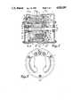
- FIG. 1is a vertical section of the alternator along the line I--I of FIG. 2;
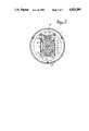
- FIG. 2is a front elevation of the alternator
- FIGS. 3, 4 and 5are cross sections of the alternator, along lines III--III, IV--IV and V--V of FIG. 1 respectively.
- the alternatorhas a housing 1 in which two roller bearings 2-3 are installed in which a rotating shaft 4 rests. Furthermore in this housing there is a stator 5 with windings 6 for three-phase alternating current the inner shell of which is conical in form. On shaft 4 four sunk keys 7 are arranged in cross form over which four keyways 8 arranged in cross form fit which have been provided in the central opening 9 of the conical rotor 10 which is provided with built-in permanent magnets 11 of alternating polarity.
- rotor 10is mounted to the shaft 4 in such a way that it can rotate and slide axially along the shaft, which means that the distance between the rotor and the stator is variable, so that the magnetizing current and consequently the current of induction can be adjusted.
- a chamber 12which contains a main compression spring 13 which on the one hand presses against a thrust plate 14 applied over the shaft 4 and on the other hand presses against a thrust ring 15 which can be shifted by means of setting bolts 16 in the chamber 12 in order to adjust the pressure of the main spring 13.
- This main compression springpresses the rotor 10 out of the stator 5 until is meets a disc 17 mounted on the shaft which itself is retained on the shaft by an intermediate disc 18 and a nut 19.
- a second chamber 20is provided in which an auxiliary compression spring 21 weaker than the main spring 13 is installed and which presses on the one hand against rotor 10 and on the other hand presses against disc 17, in such a way that this spring tries to push the rotor in the direction of the stator.
- a centrifugal voltage controller 22for adjusting the voltage of the supply current is installed.
- This controllerconsists of a collar 23 which is held in position by means of screws 24 on shaft 4.
- Two pairs of arms 26 swivelling on spindles 25 and both provided with a weight 27are mounted on this collar. Each arm has a cam end 28 which operates in conjunction with the thrust plate 14.
- each weight 27is limited by a striker 29 which operates in conjunction with a striker plate 30 on the collar.
- Two tension springs 31are attached between the two pairs of arms 26 and which subject them to tension.
- the alternatoris provided with rectifiers of a known type 32 for the conversion of the three-phase alternating current into direct current.
Landscapes
- Engineering & Computer Science (AREA)
- Power Engineering (AREA)
- Permanent Magnet Type Synchronous Machine (AREA)
- Connection Of Motors, Electrical Generators, Mechanical Devices, And The Like (AREA)
- Synchronous Machinery (AREA)
Abstract
Description
The invention is for an alternator or synchronous generator, principally for supplying electrical current to batteries and other apparatus in cars, ships, aeroplanes and other means of transport.
In a known alternator use is made among other things of a rotor winding, carbon brushes and a relatively complicated current and voltage controller. In this alternator the current and voltage controller is dependent on a control relay and the current input in the rotor winding. A disadvantage of this is that in the event of a defect in the relay this gives rise in a short period of time to a disturbance in the alternator, the battery or in other equipment.
In the alternator pursuant to the invention these advantages are countered by the fact that the rotor winding and the carbon brushes are dispensed with and the relatively complicated current and voltage controller is simplified.
Moreover this alternator has the advantage that it can be constructed relatively cheaply because the aforementioned parts are dispensed with and permanent magnets are used in the rotor. Another advantage is that the alternator works smoothly in all circumstances regardless of the speed of revolution of the motors of the means of transport which are to be supplied.
The principle characteristic of this alternator is described in claim no. 1 following below.
As an example, but without in any way attempting to be exhaustive, a more detailed description of a preferred embodiment of the alternator in accordance with the invention is given below. This description refers to the attached drawings where:
FIG. 1 is a vertical section of the alternator along the line I--I of FIG. 2;
FIG. 2 is a front elevation of the alternator;
FIGS. 3, 4 and 5 are cross sections of the alternator, along lines III--III, IV--IV and V--V of FIG. 1 respectively.
In these figures it can be seen that the alternator has ahousing 1 in which two roller bearings 2-3 are installed in which a rotatingshaft 4 rests. Furthermore in this housing there is astator 5 withwindings 6 for three-phase alternating current the inner shell of which is conical in form. Onshaft 4 four sunk keys 7 are arranged in cross form over which fourkeyways 8 arranged in cross form fit which have been provided in thecentral opening 9 of theconical rotor 10 which is provided with built-inpermanent magnets 11 of alternating polarity. As aresult rotor 10 is mounted to theshaft 4 in such a way that it can rotate and slide axially along the shaft, which means that the distance between the rotor and the stator is variable, so that the magnetizing current and consequently the current of induction can be adjusted. In the rotor achamber 12 is provided which contains amain compression spring 13 which on the one hand presses against athrust plate 14 applied over theshaft 4 and on the other hand presses against athrust ring 15 which can be shifted by means of settingbolts 16 in thechamber 12 in order to adjust the pressure of themain spring 13. This main compression spring presses therotor 10 out of thestator 5 until is meets adisc 17 mounted on the shaft which itself is retained on the shaft by an intermediate disc 18 and anut 19. In the rotor 10 a second chamber 20 is provided in which an auxiliary compression spring 21 weaker than themain spring 13 is installed and which presses on the one hand againstrotor 10 and on the other hand presses againstdisc 17, in such a way that this spring tries to push the rotor in the direction of the stator. On shaft 4 acentrifugal voltage controller 22 for adjusting the voltage of the supply current is installed. This controller consists of acollar 23 which is held in position by means ofscrews 24 onshaft 4. Two pairs ofarms 26 swivelling onspindles 25 and both provided with aweight 27 are mounted on this collar. Each arm has acam end 28 which operates in conjunction with thethrust plate 14. The position furthest from the shaft of eachweight 27 is limited by astriker 29 which operates in conjunction with astriker plate 30 on the collar. Twotension springs 31 are attached between the two pairs ofarms 26 and which subject them to tension. On the front the alternator is provided with rectifiers of a knowntype 32 for the conversion of the three-phase alternating current into direct current.
When therotor 10 starts to turn, current is excited in the stator winding by induction. The strength of the current depends on the speed of rotation of the rotor. During rotation themain compression spring 13 pressesrotor 10 out of thestator 5 causing the distance between rotor and stator to increase. As a result the magnetization current diminishes and consequently so does the current induction in the stator winding. When current consumption is increased a larger quantity of current flows through the winding resulting in a greater reaction force which causesrotor 10 to shift overshaft 4 towardsstator 5 with the assistance of the auxiliary spring 21. This reduces the distance betweenrotor 10 andstator 5 so that the magnetization current increases in strength just as the current induction does. As the speed of revolution ofshaft 4 androtor 10 increases,arms 26 andweights 27 ofvoltage controller 22 open outwards around thespindles 25 under the effect of centrifugal force, so that the cam ends 2B ofarms 26 exert more pressure onthrust plate 14 and consequently onmain compression spring 13. As this compression spring is morecompressed rotor 10 will slide out of the stator, so that the distance between both increases and the voltage of induced current voltage decreases. The voltage controller thus ensures that for differing speeds of the shaft and rotor and differing current consumptions the induced current voltage remains the same.
It goes without saying that the form, dimensions and mutual disposition of the components described above can differ and that moreover some of these components could be replaced by others which have the same purpose.
Claims (3)
1. Alternator, comprising in combination a housing, a hollow stator with windings fixed in said housing and having a conical inner shell, an axial rotary shaft in said housing, a rotor with a conical outer shell on said shaft and operating in conjunction with the conical inner shell of said stator, a slide between the shaft and the rotor for the axial motion of said rotor over the shaft and in said stator for the current control, a disc mounted on said shaft and dispersed near one end of said rotor, a compression spring for sliding said rotor over the shaft into said stator and arranged between said rotor and disc, a thrust plate movable over the shaft and disposed near the other end of said rotor, a thrust ring arranged around said shaft, a compression spring for sliding said rotor over the shaft out of the stator and arranged between said thrust plate and thrust ring, setting bolts working in conjunction with said thrust ring for the adjustment of the compression of said compression spring, and a centrifugal voltage controller for fine-adjusting the compression of said compression spring sliding said rotor out of the stator and keeping the induced current voltage the same, said controller fixed on said shaft and having swivel arms with weights to exert a pressure on the adjacent thrust plate and compression spring.
2. Alternator as defined in claim 1 in which the rotor has an axial chamber, housing the thrust ring and one end of the compression spring arranged between the thrust plate movable over the shaft and said thrust ring, said thrust ring being fixed to the setting bolts.
3. Alternator as defined in claim 1 in which the centrifugal voltage controller consists of a collar fixed on the rotary shaft, two pairs of arms with weights pivotally secured on said collar, a striker plate for each pair of arms and mounted on said collar, a striker between each pair of arms and operating in conjunction with said striker plate to limit the extreme positions of said arms with weights, a pair of draw springs between said two pairs of arms, each arm provided with a cam end operating in conjunction with the thrust plate free movable over the shaft.
Applications Claiming Priority (2)
| Application Number | Priority Date | Filing Date | Title |
|---|---|---|---|
| BE08700892 | 1987-08-10 | ||
| BE8700892ABE1000820A7 (en) | 1987-08-10 | 1987-08-10 | Alternator. |
Publications (1)
| Publication Number | Publication Date |
|---|---|
| US4920295Atrue US4920295A (en) | 1990-04-24 |
Family
ID=3882812
Family Applications (1)
| Application Number | Title | Priority Date | Filing Date |
|---|---|---|---|
| US07/230,534Expired - Fee RelatedUS4920295A (en) | 1987-08-10 | 1988-08-10 | Alternator |
Country Status (4)
| Country | Link |
|---|---|
| US (1) | US4920295A (en) |
| EP (1) | EP0304974A1 (en) |
| JP (1) | JPS6450744A (en) |
| BE (1) | BE1000820A7 (en) |
Cited By (38)
| Publication number | Priority date | Publication date | Assignee | Title |
|---|---|---|---|---|
| US5233254A (en)* | 1992-03-27 | 1993-08-03 | General Electric Company | Conical rotor for switched reluctance machine |
| US5486730A (en)* | 1993-03-18 | 1996-01-23 | Solar Turbines Incorporated | Rotor assembly |
| US5627419A (en)* | 1994-03-31 | 1997-05-06 | United Technologies Corporation | Self-adjusting airgap motor/generator for flywheel system |
| US5834874A (en)* | 1997-09-30 | 1998-11-10 | Outboard Marine Corporation | Alternator with mechanically adjustable output |
| US6249069B1 (en) | 1999-11-22 | 2001-06-19 | Bomardier Motor Corporation Of America | Output regulation of internal combustion engine alternator by mechanical means |
| US6492753B2 (en) | 2002-03-08 | 2002-12-10 | Dura-Trac Motors, Inc. | Brushless permanent magnet motor with variable axial rotor/stator alignment to increase speed capability |
| US6555941B1 (en)* | 2002-03-08 | 2003-04-29 | Dura-Trac Motors, Inc. | Brushless permanent magnet motor or alternator with variable axial rotor/stator alignment to increase speed capability |
| US6664694B2 (en)* | 2001-09-27 | 2003-12-16 | Tai-Her Yang | Rotor axial activation modulation of electric machinery due to centrifugal force |
| US20040041485A1 (en)* | 2002-08-27 | 2004-03-04 | Horber Ralph W. | Permanent magnet motor having flux density characteristics that are internally variable |
| US20050104469A1 (en)* | 2003-11-14 | 2005-05-19 | Zepp Lawrence P. | Brushless permanent magnet wheel motor with variable axial rotor/stator alignment |
| US20060087188A1 (en)* | 2004-10-25 | 2006-04-27 | Petro John P | Rotor-stator structure for electrodynamic machines |
| US20060087186A1 (en)* | 2004-10-25 | 2006-04-27 | Wasson Ken G | Rotor-stator structure for electrodynamic machines |
| US20070018524A1 (en)* | 2005-07-22 | 2007-01-25 | Mazda Motor Corporation | Electric machine and method of using electric machine |
| US20070108860A1 (en)* | 2003-12-01 | 2007-05-17 | Siemens Aktiengesellschaft | Motor for a fuel pump |
| US20070176427A1 (en)* | 2006-01-30 | 2007-08-02 | Society For Research And Initiatives For Sustainable Technologies And Institutions | Alternate current power generator |
| US20070205675A1 (en)* | 2004-10-25 | 2007-09-06 | Petro John P | Field pole members and methods of forming same for electrodynamic machines |
| US20070241628A1 (en)* | 2006-04-17 | 2007-10-18 | Himmelmann Richard A | Permanent magnet dynamoelectric machine with axially displaceable permanent magnet rotor assembly |
| US20080265702A1 (en)* | 2007-04-26 | 2008-10-30 | Don-Lon Yeh | Permanent magnetic brushless motor with length adjustable air gap based on load |
| US20090256430A1 (en)* | 2008-04-10 | 2009-10-15 | Burgess-Norton Mfg. Co., Inc. | Manufacture of electric motor component |
| US20100026221A1 (en)* | 2008-07-30 | 2010-02-04 | Himmelmann Richard A | Dual redundant variable field permanent magnet dynamoelectric machine |
| US20100026228A1 (en)* | 2008-07-30 | 2010-02-04 | Himmelmann Richard A | Variable field permanent magnet dynamoelectric machine |
| CN101931358A (en)* | 2010-07-06 | 2010-12-29 | 华南理工大学 | Low-speed start-up wind power generator with automatic magnetic adjustment |
| US7884522B1 (en) | 2004-10-25 | 2011-02-08 | Novatorque, Inc. | Stator and rotor-stator structures for electrodynamic machines |
| US7982350B2 (en) | 2004-10-25 | 2011-07-19 | Novatorque, Inc. | Conical magnets and rotor-stator structures for electrodynamic machines |
| US8330316B2 (en) | 2011-03-09 | 2012-12-11 | Novatorque, Inc. | Rotor-stator structures including boost magnet structures for magnetic regions in rotor assemblies disposed external to boundaries of conically-shaped spaces |
| US20130009507A1 (en)* | 2010-03-15 | 2013-01-10 | Do Tae Whan | Permanent magnet generator for stabilizing electromotive force |
| US20130028737A1 (en)* | 2011-07-25 | 2013-01-31 | Sports Art Industrial Co., Ltd. | Adjustable wind turbine generating device |
| US20130069604A1 (en)* | 2011-09-15 | 2013-03-21 | Lovejoy Controls Corp. | Permanent magnet generator |
| US8471425B2 (en) | 2011-03-09 | 2013-06-25 | Novatorque, Inc. | Rotor-stator structures including boost magnet structures for magnetic regions having angled confronting surfaces in rotor assemblies |
| US8543365B1 (en) | 2004-10-25 | 2013-09-24 | Novatorque, Inc. | Computer-readable medium, a method and an apparatus for designing and simulating electrodynamic machines implementing conical and cylindrical magnets |
| US20150171721A1 (en)* | 2013-12-18 | 2015-06-18 | Hyundai Motor Company | Air gap variable motor |
| US9093874B2 (en) | 2004-10-25 | 2015-07-28 | Novatorque, Inc. | Sculpted field pole members and methods of forming the same for electrodynamic machines |
| US20170328323A1 (en)* | 2016-05-13 | 2017-11-16 | Rolls-Royce Plc | Axial piston pump |
| CN107803569A (en)* | 2017-10-16 | 2018-03-16 | 重庆卡滨通用机械有限公司 | A kind of minitype permanent magnetism generating welding machine stepless-adjustment flow structure |
| US20190074736A1 (en)* | 2017-09-05 | 2019-03-07 | Nucleus Scientific Inc. | Permanent magnet motor with passively controlled variable rotor/stator alignment |
| DE102008026235B4 (en) | 2007-09-17 | 2019-07-25 | Volkswagen Ag | Electric machine |
| US10476360B2 (en) | 2016-09-13 | 2019-11-12 | Indigo Technologies, Inc. | Axial flux motor having rotatably coupled coil stator assemblies and methods of using same |
| US12054021B2 (en) | 2018-12-03 | 2024-08-06 | Indigo Technologies, Inc. | Multi-input, multi-output actuator and assemblies using same |
Families Citing this family (12)
| Publication number | Priority date | Publication date | Assignee | Title |
|---|---|---|---|---|
| FR2714232B1 (en)* | 1993-12-21 | 1996-01-19 | Gec Alsthom Transport Sa | Synchronous magnet machine with air gap variation. |
| US6455975B1 (en)* | 1999-12-03 | 2002-09-24 | Pacific Scientific Electro Kinetics Division | Regulated permanent magnet generator |
| JP4028322B2 (en)* | 2002-08-09 | 2007-12-26 | ヤマハ発動機株式会社 | Rotating electric machine |
| EP3358723A1 (en)* | 2002-12-20 | 2018-08-08 | Tai-Her Yang | Electrical machine with structure for axially moving the rotor using centrifugal force |
| DE102006020867A1 (en)* | 2006-05-04 | 2007-11-15 | Siemens Ag | Electrical machine, in particular permanent-magnet synchronous motor with adjustable field weakening |
| DE102007011655A1 (en)* | 2007-03-09 | 2008-09-11 | Continental Automotive Gmbh | Permanently excited electric motor has stator and rotor, where magnetic pole generates exciting field either at stator or at rotor |
| JP5164611B2 (en)* | 2008-03-04 | 2013-03-21 | 株式会社牧野フライス製作所 | Machine Tools |
| IT1392226B1 (en) | 2008-12-15 | 2012-02-22 | Appliances Components Companies S P A | "PERMANENT MAGNET ELECTRIC MOTOR" |
| JP2013165580A (en)* | 2012-02-10 | 2013-08-22 | Ulvac Japan Ltd | Power generator |
| US10530209B2 (en)* | 2016-10-28 | 2020-01-07 | Waymo Llc | Devices and methods for driving a rotary platform |
| CN108667164A (en)* | 2018-05-30 | 2018-10-16 | 宁波诺丁汉大学 | Permanent magnet conical motor with stator and rotor |
| US12009702B2 (en)* | 2022-05-18 | 2024-06-11 | Hamilton Sundstrand Corporation | Permanent magnet generator systems |
Citations (14)
| Publication number | Priority date | Publication date | Assignee | Title |
|---|---|---|---|---|
| US646309A (en)* | 1898-06-07 | 1900-03-27 | Albert Koppitz | Induction-motor. |
| US1039197A (en)* | 1909-11-03 | 1912-09-24 | Charles H Roth | Variable-speed electric generator. |
| US1194645A (en)* | 1916-08-15 | lincoln | ||
| US1763104A (en)* | 1927-05-25 | 1930-06-10 | Herman Nelson Corp | Variable-speed alpha c motors |
| US1935005A (en)* | 1931-06-08 | 1933-11-14 | Stone J & Co Ltd | Bulkhead door, sluice gate, and the like |
| US1979445A (en)* | 1931-12-30 | 1934-11-06 | Gen Motors Corp | Centrifugal switch |
| US2072008A (en)* | 1935-02-07 | 1937-02-23 | Reliance Electric & Eng Co | Adjustable speed electric motor |
| US2492810A (en)* | 1948-08-02 | 1949-12-27 | Mcdermott Carl | Electric light generator for motor scooters and the like |
| DE839224C (en)* | 1949-11-08 | 1952-05-19 | Werner Braun | Magnetic electric small machine with changing drive speed |
| FR1009925A (en)* | 1948-07-12 | 1952-06-05 | Kampnagel Ag | Electrical apparatus intended to produce a kinetic adjusting force, for example to release brakes, disengage couplings, etc. |
| GB733975A (en)* | 1952-10-01 | 1955-07-20 | Bendix Aviat Corp | Improvements in or relating to alternators |
| DE1088600B (en)* | 1958-09-09 | 1960-09-08 | Siemens Ag | Electric power generator, especially for use as an alternator |
| US3299335A (en)* | 1963-03-12 | 1967-01-17 | Philips Corp | Self-starting direct-current motors having no commutator |
| SU626470A1 (en)* | 1976-05-03 | 1978-09-30 | Предприятие П/Я А-7677 | Reduction synchronous electric motor |
Family Cites Families (3)
| Publication number | Priority date | Publication date | Assignee | Title |
|---|---|---|---|---|
| DE726020C (en)* | 1938-11-19 | 1942-10-05 | Demag Ag | Electric drive with controllable coupling for conveyor reel or the like. |
| DE929911C (en)* | 1950-05-04 | 1955-07-07 | Demag Zug Gmbh | Device for releasing the brake of sliding armature motors |
| DE1488273A1 (en)* | 1964-05-26 | 1969-08-14 | Garrett Corp | Alternator |
- 1987
- 1987-08-10BEBE8700892Apatent/BE1000820A7/ennot_activeIP Right Cessation
- 1988
- 1988-07-18EPEP88201547Apatent/EP0304974A1/ennot_activeWithdrawn
- 1988-08-03JPJP63194278Apatent/JPS6450744A/enactivePending
- 1988-08-10USUS07/230,534patent/US4920295A/ennot_activeExpired - Fee Related
Patent Citations (14)
| Publication number | Priority date | Publication date | Assignee | Title |
|---|---|---|---|---|
| US1194645A (en)* | 1916-08-15 | lincoln | ||
| US646309A (en)* | 1898-06-07 | 1900-03-27 | Albert Koppitz | Induction-motor. |
| US1039197A (en)* | 1909-11-03 | 1912-09-24 | Charles H Roth | Variable-speed electric generator. |
| US1763104A (en)* | 1927-05-25 | 1930-06-10 | Herman Nelson Corp | Variable-speed alpha c motors |
| US1935005A (en)* | 1931-06-08 | 1933-11-14 | Stone J & Co Ltd | Bulkhead door, sluice gate, and the like |
| US1979445A (en)* | 1931-12-30 | 1934-11-06 | Gen Motors Corp | Centrifugal switch |
| US2072008A (en)* | 1935-02-07 | 1937-02-23 | Reliance Electric & Eng Co | Adjustable speed electric motor |
| FR1009925A (en)* | 1948-07-12 | 1952-06-05 | Kampnagel Ag | Electrical apparatus intended to produce a kinetic adjusting force, for example to release brakes, disengage couplings, etc. |
| US2492810A (en)* | 1948-08-02 | 1949-12-27 | Mcdermott Carl | Electric light generator for motor scooters and the like |
| DE839224C (en)* | 1949-11-08 | 1952-05-19 | Werner Braun | Magnetic electric small machine with changing drive speed |
| GB733975A (en)* | 1952-10-01 | 1955-07-20 | Bendix Aviat Corp | Improvements in or relating to alternators |
| DE1088600B (en)* | 1958-09-09 | 1960-09-08 | Siemens Ag | Electric power generator, especially for use as an alternator |
| US3299335A (en)* | 1963-03-12 | 1967-01-17 | Philips Corp | Self-starting direct-current motors having no commutator |
| SU626470A1 (en)* | 1976-05-03 | 1978-09-30 | Предприятие П/Я А-7677 | Reduction synchronous electric motor |
Cited By (68)
| Publication number | Priority date | Publication date | Assignee | Title |
|---|---|---|---|---|
| US5233254A (en)* | 1992-03-27 | 1993-08-03 | General Electric Company | Conical rotor for switched reluctance machine |
| US5486730A (en)* | 1993-03-18 | 1996-01-23 | Solar Turbines Incorporated | Rotor assembly |
| US5627419A (en)* | 1994-03-31 | 1997-05-06 | United Technologies Corporation | Self-adjusting airgap motor/generator for flywheel system |
| US5834874A (en)* | 1997-09-30 | 1998-11-10 | Outboard Marine Corporation | Alternator with mechanically adjustable output |
| US6249069B1 (en) | 1999-11-22 | 2001-06-19 | Bomardier Motor Corporation Of America | Output regulation of internal combustion engine alternator by mechanical means |
| US6664694B2 (en)* | 2001-09-27 | 2003-12-16 | Tai-Her Yang | Rotor axial activation modulation of electric machinery due to centrifugal force |
| US6492753B2 (en) | 2002-03-08 | 2002-12-10 | Dura-Trac Motors, Inc. | Brushless permanent magnet motor with variable axial rotor/stator alignment to increase speed capability |
| US6555941B1 (en)* | 2002-03-08 | 2003-04-29 | Dura-Trac Motors, Inc. | Brushless permanent magnet motor or alternator with variable axial rotor/stator alignment to increase speed capability |
| US20040041485A1 (en)* | 2002-08-27 | 2004-03-04 | Horber Ralph W. | Permanent magnet motor having flux density characteristics that are internally variable |
| US6844647B2 (en)* | 2002-08-27 | 2005-01-18 | Seiberco Incorporated | Permanent magnet motor having flux density characteristics that are internally variable |
| US20050104469A1 (en)* | 2003-11-14 | 2005-05-19 | Zepp Lawrence P. | Brushless permanent magnet wheel motor with variable axial rotor/stator alignment |
| US6943478B2 (en) | 2003-11-14 | 2005-09-13 | Dura-Trac Motors, Inc. | Brushless permanent magnet wheel motor with variable axial rotor/stator alignment |
| US20060049712A1 (en)* | 2003-11-14 | 2006-03-09 | Zepp Lawrence P | Brushless permanent magnet wheel motor with variable axial rotor/stator alignment |
| US7042128B2 (en) | 2003-11-14 | 2006-05-09 | Dura-Trac Motors, Inc. | Brushless permanent magnet wheel motor with variable axial rotor/stator alignment |
| US20070108860A1 (en)* | 2003-12-01 | 2007-05-17 | Siemens Aktiengesellschaft | Motor for a fuel pump |
| US7345399B2 (en)* | 2003-12-01 | 2008-03-18 | Siemens Aktiengesellschaft | Motor for a fuel pump |
| US7205693B2 (en) | 2004-10-25 | 2007-04-17 | Novatorque, Inc. | Rotor-stator structure for electrodynamic machines |
| US8283832B2 (en) | 2004-10-25 | 2012-10-09 | Novatorque, Inc. | Sculpted field pole members and methods of forming the same for electrodynamic machines |
| US20060152099A1 (en)* | 2004-10-25 | 2006-07-13 | Petro John P | Rotor-stator structure for electrodynamic machines |
| US7884522B1 (en) | 2004-10-25 | 2011-02-08 | Novatorque, Inc. | Stator and rotor-stator structures for electrodynamic machines |
| US8330317B2 (en) | 2004-10-25 | 2012-12-11 | Novatorque, Inc. | Conical magnets and rotor-stator structures for electrodynamic machines |
| US7061152B2 (en) | 2004-10-25 | 2006-06-13 | Novatorque, Inc. | Rotor-stator structure for electrodynamic machines |
| US7239058B2 (en) | 2004-10-25 | 2007-07-03 | Novatorque, Inc. | Rotor-stator structure for electrodynamic machines |
| US20060087188A1 (en)* | 2004-10-25 | 2006-04-27 | Petro John P | Rotor-stator structure for electrodynamic machines |
| US20070205675A1 (en)* | 2004-10-25 | 2007-09-06 | Petro John P | Field pole members and methods of forming same for electrodynamic machines |
| US9093874B2 (en) | 2004-10-25 | 2015-07-28 | Novatorque, Inc. | Sculpted field pole members and methods of forming the same for electrodynamic machines |
| US7294948B2 (en) | 2004-10-25 | 2007-11-13 | Novatorque, Inc. | Rotor-stator structure for electrodynamic machines |
| US20060087186A1 (en)* | 2004-10-25 | 2006-04-27 | Wasson Ken G | Rotor-stator structure for electrodynamic machines |
| US8543365B1 (en) | 2004-10-25 | 2013-09-24 | Novatorque, Inc. | Computer-readable medium, a method and an apparatus for designing and simulating electrodynamic machines implementing conical and cylindrical magnets |
| US20060145555A1 (en)* | 2004-10-25 | 2006-07-06 | Petro John P | Rotor-stator structure for electrodynamic machines |
| US7982350B2 (en) | 2004-10-25 | 2011-07-19 | Novatorque, Inc. | Conical magnets and rotor-stator structures for electrodynamic machines |
| US7622840B2 (en) | 2005-07-22 | 2009-11-24 | Mazda Motor Corporation | Electric machine and method of using electric machine |
| US20070018524A1 (en)* | 2005-07-22 | 2007-01-25 | Mazda Motor Corporation | Electric machine and method of using electric machine |
| US7382074B2 (en)* | 2006-01-30 | 2008-06-03 | Society For Research And Initiatives For Sustainable Technologies And Institutions | Alternate current power generator |
| US20070176427A1 (en)* | 2006-01-30 | 2007-08-02 | Society For Research And Initiatives For Sustainable Technologies And Institutions | Alternate current power generator |
| US7385332B2 (en)* | 2006-04-17 | 2008-06-10 | Hamilton Sundstrand Corporation | Permanent magnet dynamoelectric machine with axially displaceable permanent magnet rotor assembly |
| US20070241628A1 (en)* | 2006-04-17 | 2007-10-18 | Himmelmann Richard A | Permanent magnet dynamoelectric machine with axially displaceable permanent magnet rotor assembly |
| US20080265702A1 (en)* | 2007-04-26 | 2008-10-30 | Don-Lon Yeh | Permanent magnetic brushless motor with length adjustable air gap based on load |
| DE102008026235B4 (en) | 2007-09-17 | 2019-07-25 | Volkswagen Ag | Electric machine |
| US7847443B2 (en)* | 2008-04-10 | 2010-12-07 | Burgess-Norton Mfg. Co., Inc. | Manufacture of electric motor component |
| US20090256430A1 (en)* | 2008-04-10 | 2009-10-15 | Burgess-Norton Mfg. Co., Inc. | Manufacture of electric motor component |
| CN101557129B (en)* | 2008-04-10 | 2013-03-27 | 伯吉斯-诺顿制造有限公司 | Manufacture of electric motor component |
| US20100026221A1 (en)* | 2008-07-30 | 2010-02-04 | Himmelmann Richard A | Dual redundant variable field permanent magnet dynamoelectric machine |
| US20100026228A1 (en)* | 2008-07-30 | 2010-02-04 | Himmelmann Richard A | Variable field permanent magnet dynamoelectric machine |
| US7956565B2 (en) | 2008-07-30 | 2011-06-07 | Hamilton Sundstrand Corporation | Variable field permanent magnet dynamoelectric machine |
| US7948192B2 (en) | 2008-07-30 | 2011-05-24 | Hamilton Sundstrand Corporation | Dual redundant variable field permanent magnet dynamoelectric machine |
| US20130009507A1 (en)* | 2010-03-15 | 2013-01-10 | Do Tae Whan | Permanent magnet generator for stabilizing electromotive force |
| US9013079B2 (en)* | 2010-03-15 | 2015-04-21 | Tae whan Do | Permanent magnet generator for stabilizing electromotive force |
| CN101931358A (en)* | 2010-07-06 | 2010-12-29 | 华南理工大学 | Low-speed start-up wind power generator with automatic magnetic adjustment |
| US8471425B2 (en) | 2011-03-09 | 2013-06-25 | Novatorque, Inc. | Rotor-stator structures including boost magnet structures for magnetic regions having angled confronting surfaces in rotor assemblies |
| US8330316B2 (en) | 2011-03-09 | 2012-12-11 | Novatorque, Inc. | Rotor-stator structures including boost magnet structures for magnetic regions in rotor assemblies disposed external to boundaries of conically-shaped spaces |
| US20130028737A1 (en)* | 2011-07-25 | 2013-01-31 | Sports Art Industrial Co., Ltd. | Adjustable wind turbine generating device |
| US20130069604A1 (en)* | 2011-09-15 | 2013-03-21 | Lovejoy Controls Corp. | Permanent magnet generator |
| US8823331B2 (en)* | 2011-09-15 | 2014-09-02 | Lovejoy Controls Corporation | Permanent magnet generator |
| US20150171721A1 (en)* | 2013-12-18 | 2015-06-18 | Hyundai Motor Company | Air gap variable motor |
| US10677207B2 (en)* | 2016-05-13 | 2020-06-09 | Rolls-Royce Plc | Axial piston pump having a piston housing having fixed field members mounted thereto and interacting with a stator surrounding the housing and configured to generate a force which urges the housing in an axial direction |
| US20170328323A1 (en)* | 2016-05-13 | 2017-11-16 | Rolls-Royce Plc | Axial piston pump |
| US10476360B2 (en) | 2016-09-13 | 2019-11-12 | Indigo Technologies, Inc. | Axial flux motor having rotatably coupled coil stator assemblies and methods of using same |
| US10483832B2 (en) | 2016-09-13 | 2019-11-19 | Indigo Technologies, Inc. | Multi-bar linkage electric drive system |
| US10644578B2 (en) | 2016-09-13 | 2020-05-05 | Indigo Technologies, Inc. | Guided multi-bar linkage electric drive system |
| US10938285B2 (en) | 2016-09-13 | 2021-03-02 | Indigo Technologies, Inc. | Multi-bar linkage electric drive system |
| US11368076B2 (en) | 2016-09-13 | 2022-06-21 | Indigo Technologies, Inc. | Multi-bar linkage electric drive system |
| US12170468B2 (en) | 2016-09-13 | 2024-12-17 | Indigo Technologies, Inc. | Multi-bar linkage electric drive system |
| US20190074736A1 (en)* | 2017-09-05 | 2019-03-07 | Nucleus Scientific Inc. | Permanent magnet motor with passively controlled variable rotor/stator alignment |
| US10763713B2 (en)* | 2017-09-05 | 2020-09-01 | Indigo Technologies, Inc. | Permanent magnet motor with passively controlled variable rotor/stator alignment |
| US20210044165A1 (en)* | 2017-09-05 | 2021-02-11 | Indigo Technologies, Inc. | Permanent Magnet Motor with Passively Controlled Variable Rotor/Stator Alignment |
| CN107803569A (en)* | 2017-10-16 | 2018-03-16 | 重庆卡滨通用机械有限公司 | A kind of minitype permanent magnetism generating welding machine stepless-adjustment flow structure |
| US12054021B2 (en) | 2018-12-03 | 2024-08-06 | Indigo Technologies, Inc. | Multi-input, multi-output actuator and assemblies using same |
Also Published As
| Publication number | Publication date |
|---|---|
| JPS6450744A (en) | 1989-02-27 |
| BE1000820A7 (en) | 1989-04-11 |
| EP0304974A1 (en) | 1989-03-01 |
Similar Documents
| Publication | Publication Date | Title |
|---|---|---|
| US4920295A (en) | Alternator | |
| US4879484A (en) | Alternating current generator and method of angularly adjusting the relative positions of rotors thereof | |
| US4462467A (en) | Percussion drill machine | |
| US4044274A (en) | Transmission system | |
| SU1283002A1 (en) | Electrode wire feed device | |
| RU2481157C2 (en) | Roll mill | |
| CN213693357U (en) | Magnetic suspension driving motor device in unmanned aerial vehicle power system | |
| US1039197A (en) | Variable-speed electric generator. | |
| JP2000502875A (en) | Electric motor | |
| CN106655609B (en) | A kind of Moving adjusting electromechanical actuator | |
| CN109091795A (en) | damping motor structure and body-building system | |
| US2403243A (en) | Synchronizing propeller | |
| AU2023222855A1 (en) | Electric Motor | |
| US4496864A (en) | Brake motor | |
| US2309904A (en) | Electric motor | |
| US2441605A (en) | Constant speed dynamoelectric power transmission unit | |
| CN106800224A (en) | A kind of unmanned plane list drives cable pulling-pushing device | |
| US1079008A (en) | Dynamo-electric generator. | |
| CN206735540U (en) | A kind of unmanned plane list drives cable pulling-pushing device | |
| GB2062974A (en) | Electric motor | |
| JPH02197493A (en) | Electrically driven contra-rotating propeller | |
| CN111313644B (en) | Motor rotor structure and permanent magnet synchronous motor | |
| DE3403769A1 (en) | Device for energy conversion | |
| US1298757A (en) | Dynamo-electric machine. | |
| US1251645A (en) | Reversible brush-holder for use with dynamos. |
Legal Events
| Date | Code | Title | Description |
|---|---|---|---|
| LAPS | Lapse for failure to pay maintenance fees | ||
| FP | Lapsed due to failure to pay maintenance fee | Effective date:19940705 | |
| STCH | Information on status: patent discontinuation | Free format text:PATENT EXPIRED DUE TO NONPAYMENT OF MAINTENANCE FEES UNDER 37 CFR 1.362 |