US4919508A - Fiberoptic coupler - Google Patents
Fiberoptic couplerDownload PDFInfo
- Publication number
- US4919508A US4919508AUS07/228,278US22827888AUS4919508AUS 4919508 AUS4919508 AUS 4919508AUS 22827888 AUS22827888 AUS 22827888AUS 4919508 AUS4919508 AUS 4919508A
- Authority
- US
- United States
- Prior art keywords
- optical fiber
- male plug
- catheter
- locating pin
- handle region
- Prior art date
- Legal status (The legal status is an assumption and is not a legal conclusion. Google has not performed a legal analysis and makes no representation as to the accuracy of the status listed.)
- Expired - Lifetime
Links
- 239000013307optical fiberSubstances0.000claimsabstractdescription52
- 239000000835fiberSubstances0.000claimsdescription19
- 230000003213activating effectEffects0.000claims1
- 230000013011matingEffects0.000claims1
- 230000008878couplingEffects0.000abstractdescription8
- 238000010168coupling processMethods0.000abstractdescription8
- 238000005859coupling reactionMethods0.000abstractdescription8
- 230000003287optical effectEffects0.000description10
- 239000000463materialSubstances0.000description4
- 210000004204blood vesselAnatomy0.000description3
- 239000003990capacitorSubstances0.000description3
- 238000000034methodMethods0.000description2
- 229920002379silicone rubberPolymers0.000description2
- 241000220010RhodeSpecies0.000description1
- 238000002679ablationMethods0.000description1
- 230000000903blocking effectEffects0.000description1
- 238000010586diagramMethods0.000description1
- 239000003814drugSubstances0.000description1
- 210000004013groinAnatomy0.000description1
- 238000003780insertionMethods0.000description1
- 230000037431insertionEffects0.000description1
- 238000007689inspectionMethods0.000description1
- 238000002955isolationMethods0.000description1
- 239000002184metalSubstances0.000description1
- 238000012986modificationMethods0.000description1
- 230000004048modificationEffects0.000description1
- 210000000056organAnatomy0.000description1
- 239000004033plasticSubstances0.000description1
- 235000020004porterNutrition0.000description1
- 239000000523sampleSubstances0.000description1
- 238000012163sequencing techniqueMethods0.000description1
- 230000001960triggered effectEffects0.000description1
Images


Classifications
- A—HUMAN NECESSITIES
- A61—MEDICAL OR VETERINARY SCIENCE; HYGIENE
- A61B—DIAGNOSIS; SURGERY; IDENTIFICATION
- A61B18/00—Surgical instruments, devices or methods for transferring non-mechanical forms of energy to or from the body
- A61B18/18—Surgical instruments, devices or methods for transferring non-mechanical forms of energy to or from the body by applying electromagnetic radiation, e.g. microwaves
- A61B18/20—Surgical instruments, devices or methods for transferring non-mechanical forms of energy to or from the body by applying electromagnetic radiation, e.g. microwaves using laser
- A61B18/22—Surgical instruments, devices or methods for transferring non-mechanical forms of energy to or from the body by applying electromagnetic radiation, e.g. microwaves using laser the beam being directed along or through a flexible conduit, e.g. an optical fibre; Couplings or hand-pieces therefor
- A61B18/24—Surgical instruments, devices or methods for transferring non-mechanical forms of energy to or from the body by applying electromagnetic radiation, e.g. microwaves using laser the beam being directed along or through a flexible conduit, e.g. an optical fibre; Couplings or hand-pieces therefor with a catheter
- G—PHYSICS
- G02—OPTICS
- G02B—OPTICAL ELEMENTS, SYSTEMS OR APPARATUS
- G02B6/00—Light guides; Structural details of arrangements comprising light guides and other optical elements, e.g. couplings
- G02B6/24—Coupling light guides
- G02B6/36—Mechanical coupling means
- G02B6/38—Mechanical coupling means having fibre to fibre mating means
- G02B6/3807—Dismountable connectors, i.e. comprising plugs
- G02B6/381—Dismountable connectors, i.e. comprising plugs of the ferrule type, e.g. fibre ends embedded in ferrules, connecting a pair of fibres
- G02B6/3813—Dismountable connectors, i.e. comprising plugs of the ferrule type, e.g. fibre ends embedded in ferrules, connecting a pair of fibres for transmission of high energy beam
- G—PHYSICS
- G02—OPTICS
- G02B—OPTICAL ELEMENTS, SYSTEMS OR APPARATUS
- G02B6/00—Light guides; Structural details of arrangements comprising light guides and other optical elements, e.g. couplings
- G02B6/24—Coupling light guides
- G02B6/42—Coupling light guides with opto-electronic elements
- G02B6/4296—Coupling light guides with opto-electronic elements coupling with sources of high radiant energy, e.g. high power lasers, high temperature light sources
- A—HUMAN NECESSITIES
- A61—MEDICAL OR VETERINARY SCIENCE; HYGIENE
- A61B—DIAGNOSIS; SURGERY; IDENTIFICATION
- A61B17/00—Surgical instruments, devices or methods
- A61B2017/00477—Coupling
- A61B2017/00482—Coupling with a code
- A—HUMAN NECESSITIES
- A61—MEDICAL OR VETERINARY SCIENCE; HYGIENE
- A61B—DIAGNOSIS; SURGERY; IDENTIFICATION
- A61B18/00—Surgical instruments, devices or methods for transferring non-mechanical forms of energy to or from the body
- A61B2018/00053—Mechanical features of the instrument of device
- A61B2018/00172—Connectors and adapters therefor
- G—PHYSICS
- G02—OPTICS
- G02B—OPTICAL ELEMENTS, SYSTEMS OR APPARATUS
- G02B6/00—Light guides; Structural details of arrangements comprising light guides and other optical elements, e.g. couplings
- G02B6/24—Coupling light guides
- G02B6/42—Coupling light guides with opto-electronic elements
- G02B6/4296—Coupling light guides with opto-electronic elements coupling with sources of high radiant energy, e.g. high power lasers, high temperature light sources
- G02B2006/4297—Coupling light guides with opto-electronic elements coupling with sources of high radiant energy, e.g. high power lasers, high temperature light sources having protection means, e.g. protecting humans against accidental exposure to harmful laser radiation
- G—PHYSICS
- G02—OPTICS
- G02B—OPTICAL ELEMENTS, SYSTEMS OR APPARATUS
- G02B6/00—Light guides; Structural details of arrangements comprising light guides and other optical elements, e.g. couplings
- G02B6/24—Coupling light guides
- G02B6/36—Mechanical coupling means
- G02B6/38—Mechanical coupling means having fibre to fibre mating means
- G02B6/3807—Dismountable connectors, i.e. comprising plugs
- G02B6/3887—Anchoring optical cables to connector housings, e.g. strain relief features
- G02B6/3889—Anchoring optical cables to connector housings, e.g. strain relief features using encapsulation for protection, e.g. adhesive, molding or casting resin
Definitions
- the inventionrelates to an apparatus for coupling an optical fiber to a laser light source. More particularly, this invention relates to a quick disconnect coupler which can mate optical fibers of varying size to a laser light source, the coupler of this invention being able to detect information concerning a characteristic such as size, of the optical fiber being mated to the laser light source.
- optical fiber cathetersIn the field of medicine, it is desirable to insert optical fiber catheters into the human body to probe and inspect various portions of the body.
- One such techniqueis to surgically insert a catheter into a main blood vessel and pass the catheter to various organs, such as the heart, for inspection.
- a technique being used todayis to insert an optical fiber catheter attached to a laser energy source into the body and then use laser pulses to destroy materials blocking blood vessels or remove any material towards which the optical fiber catheter directs the laser energy.
- each cathetercan be employed with only one patient. Accordingly, the catheters are disposable. Since the size of the blood vessels in human bodies varies according to age and physical attributes, different size fiberoptic catheters are needed. Therefore, a quick connect/disconnect feature for attaching the fiberoptic catheter to a laser light source is needed.
- the optical coupler for attaching an optical fiber catheter to a laser sourcemust accurately align the optical fiber with the light source to permit near 100% coupling of the laser light into the optical fiber. This requires a particularly accurate coupler.
- Optical fiber couplerssuch as those disclosed in U.S. Pat. No. 4,435,036 to Sasakawa and U.S. Pat. No. 4,607,911 to Rhodes show the use of a two part connector, the two parts being coupled by threaded engagement. Neither coupler is of a quick disconnect design nor does the coupler provide any information about the optical fibers being coupled. Likewise, the directional coupler disclosed in U.S. Pat. No. 4,423,922 to Porter uses a threaded engagement of an optical fiber and does not provide any information about the fiber being coupled.
- the optical couplershould recognize the size of fiber catheter to which it is coupling so that the energy emitted by the laser can be controlled.
- the present inventionis a quick disconnect coupler for an optical fiber which accurately aligns the optical fiber to a laser light source and conveys information concerning a characteristic of the fiber, such as the size of the fiber which is being coupled.
- the couplercomprises a first connector portion having a locking grove which permits accurate alignment of the fiber to a second connector portion mounted on the laser light source.
- a means for providing information indicative of the optical fiberis contained in the first connector portion.
- the second connector portionis removably connected to the first connector portion and contains means for decoding information about the fiber to which it is being coupled.
- Informationmay be coded in the first connector portion by a series of grooves whose position and number provide information as to its optical fiber size.
- a series of sensors contained in the second connector portion of the couplerdetermines the coding of the grooves and provides information as to the size, e.g., diameter, of the fiber being coupled to the laser light source.
- the couplermay have a male locating pin contained in the first connector portion and a cooperating female receptacle in the second connector portion.
- a series of grooves in the male locating pinmay provide information which can be decoded by a series of microswitches in the female receptacle.
- informationmay be coded in the first connector portion by a series of relief openings or slots whose presence and location are related to the optical fiber characteristics.
- a series of sensors contained in the second connector portiondetermines the coding of the relief openings and provides information as to the size, diameter, or other characteristics of the fiber catheter being coupled to the laser light source.
- the preferred embodimentis described in relation to a fiber delivery system adapted to be inserted in a subject through a catheter.
- the present inventioncan be employed with other applications in which laser energy is directed along an optical fiber.
- FIG. 1is a diagram of the laser fiberoptic catheter system employing the coupler of the present invention
- FIG. 2ais a drawing of the male portion of the optical fiber catheter
- FIG. 2bis a cross-sectional view of the coupler in a mated position
- FIG. 3is a detailed view of an electrical microswitch sensing a groove
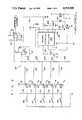
- FIG. 4is a schematic drawing of a circuit for determining the presence and size of a fiberoptic catheter
- FIG. 5is a cross-sectional view of an alternative embodiment of the coupler shown in a mated position
- FIG. 6is a cross-sectional view of the male portion showing the relief openings
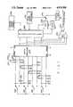
- FIG. 7is a schematic drawing of a microprocessor controlled circuit for use with the invention.
- FIG. 8is a flow chart of the microprocessor sequencing within the circuit of FIG. 7.
- FIG. 1Shown in FIG. 1 is a layout of the overall system employing the fiberoptic coupler of the present invention.
- a laser source 10contains the power supplies and laser optics to output a laser light beam of a desired energy level.
- the laseris controlled by a remote isolation controller 12 which controls the intensity and duration of the laser pulse via an optically isolated cable 14.
- Optical coupler 20 of the present inventionconnects a fiberoptical catheter 22 to laser source 10. Fiberoptic catheter 22 can be surgically inserted into the groin or other area of a patient 40.
- electronic circuit 60Associated within laser source 10 is electronic circuit 60 used in conjunction with optical coupler 20 to determine the presence and size of fiberoptic catheter 22 which is connected to laser source 10.
- Fiberoptic coupler 20 as shown in FIG. 2acomprises a male plug portion 30 having a locating pin 32 which is clad about or coupled to an end of fiberoptic catheter 22.
- Male plug 30contains a locking groove 34 and fiber diameter indicating grooves 36.
- Tip 38 of locating pin 32is tapered to allow easy insertion of the pin within the female receptacle portion of the optical coupler.
- Enlargement 40 of male plug portion 30can be used as a handle and provides a means for grasping and inserting a disposable catheter into the female portion.
- Enlarged region 40may be plastic and have a silicon rubber support 42 extending away from the handle towards fiberoptic catheter 22 to provide support for and smooth flexing of catheter 22.
- FIG. 2bA cross-sectional view of fiberoptic coupler 20 in a mated position is shown in FIG. 2b.
- Female receptacle portion 44 of optical coupler 20is connected to receive energy from laser source 10.
- Locating pin 32can be seated within metal female housing 44 which contains a spring loaded locking plunger 46 which presses against locking groove 34 to provide a rigid and accurate alignment of tip end 38 of male plug portion 30. This accurately aligns the optical fiber of catheter 22 to laser source 10.
- Also contained within housing 44is a series of microswitches 48, 50, 52, 54 and 56 which sense the presence or absence of size indicating grooves 36 at corresponding locations along locating pin 32.
- Microswitch 48is shown in detail in FIG. 3 wherein an actuating member 62 causes contacts of switch 48 to be opened or closed depending upon whether a groove is located in a position to depress actuating member 62. Electrical connections are made to microswitch 48 via leads 64.
- the switchis of standard commercially available design and can be electrically connected to be either normally opened or normally closed.
- the output of the switchesis sensed by circuit 60 shown in detail in FIG. 4 wherein switches 48-56 are shown as making contact to ground when closed.
- switches 48-56are shown as making contact to ground when closed.
- Connected to each switchis a transistor network containing pull up resistors 70, 72, 74 76 and 78 connected to transistors 80, 82, 84, 86 and 88, respectively, as shown.
- Transistors 80-88have load resistors 79, 81, 83, 85 and 87, respectively, connecting the transistors to a power supply.
- the emitter of each transistoris connected to ground. When one of microswitches is closed, the associated transistor has its base voltage grounded causing the voltage at the collector to rise to approximately the power supply voltage.
- the conduction states of transistors 80-88cause currents to flow through resistors 90, 92, 94, 96 and 98 which, in turn, cause voltage drops across resistors 100, 102, 104, 106 and 108.
- a voltageis applied to operational amplifier 110.
- This voltageis uniquely related to which of switches 48-56 is closed.
- the voltage applied to amplifier 110contains information concerning which combination of switches is closed.
- the gain of operational amplifier 110is controlled, in part, by the value of resistor 112.
- the output of amplifier 110is a DC analog voltage which is related to which of switches 48-56 are opened or closed.
- the analog outputis applied through resistor 116 to a voltage controlled oscillator 120.
- Voltage controlled oscillator 120can be fine-tuned by resistors 122, 124, 126, 132 and 134 and capacitors 128 and 130 to produce an AC output whose frequency is directly related to DC voltage input, and therefore, to which of switches 48-56 are closed.
- This AC output of voltage controlled oscillator 120is through buffer transistor 146 with optical coupling provided by photodiode 140 and photo transistor 150 to remote controller 12 which uses the frequency of the signal to control the energy emitted per pulse by laser source 10.
- the output across the resistor network 100-108is provided to one input of operational amplifier 160.
- Resistors 162 and 164set a reference voltage at the other input of amplifier 160.
- amplifier 110acts as a comparator to provide an output which is indicative of the presence of any optical fiber and can be used to control the opening and closing of a shutter of laser source 10.
- optical fiber coding of the male plug portion shown in FIG. 2bcould be coded as 01000 and correspond to a logic state represented by a binary 8.
- FIG. 5An alternate embodiment for encoding information about the optical fiber is shown in FIG. 5.
- the male plug portion 30is shown with fiberoptic catheter 22 connected to enlarged handle region 40 and having a support 42 of silicon rubber or other material.
- Enlarged handle region 40contains a number of relief slots 180 whose presence or absence is indicative of the characteristics of the fiberoptic catheter 22.
- Female housing 44contains a series of plungers 184 in longitudinal bores of the female housing 44. Plungers 184 are urged upward by springs 186 which push against the plunger 184 and spring keeper cover 188. Plungers 184 are narrowed at its one end to fit into relief slot 180, if present. At the end of plunger 184, away from male portion 30, the plunger activates a microswitch 248 having an actuating member 62 which is triggered through a lever arm 66.
- a pin 190is placed in housing 44 to rotationally align and hold housing 44 and plug 30 in a fixed position.
- one plunger 184is seated in relief slot 180 causing microswitch 250 to close while another plunger has failed to find a relief slot 180 and causes the microswitch 248 to remain open.
- FIG. 5A cross-sectional view of FIG. 5 taken through the enlarged handle region 40 showing the junction of the female housing 44 and male plug 30 is shown in FIG. 6.
- Relief slot regions 180whose presence or absence are indicative of the characteristics of the fiberoptic catheter, are placed radially about the handle region.
- Rotational alignment pin 190is shown in a bore of handle 40.
- FIG. 7A circuit for decoding information about the fiberoptic catheter which employs a microprocessor is shown in FIG. 7.
- Switches 248, 250, 252 and 254, corresponding to the microswitches shown in FIG. 5,are activated by plungers 184.
- the switchesare of a single pole double throw type and connect to a switch debouncer 270.
- Capacitors 260 and diodes 262connect the switching lines to ground or the supply voltage as shown in FIG. 7. The capacitors and diodes filter high frequency signals and high voltage spikes that might be picked up by the switch lead wires.
- the outputs of the switch debouncer 270will be high. All high signals to the input of microprocessor controller 280 indicates that there is no fiberoptic catheter in the fiberoptic coupler. When a fiberoptic catheter is present, a combination of high and low signals will indicate the diameter or other characteristic of the catheter. A total of fifteen different combinations can be decoded from a four switch input circuit.
- a synchronizer clock signal 272can be used as a strobe for the switcher debouncer 270. This will ensure that all inputs from switches 248-254 are stable when the microcontroller 280 reads its inputs.
- NAND gates 290 and 291 and NOR gate 293are used to generate via hardware a signal indicating that a catheter is not in place. This signal is used as an input signal to an EPROM which performs a hardware-software error check. A low voltage signal indicates a catheter is not in place and a high signal indicates that a fiber is in place.
- Microprocessor 280controls the laser power output to the fiberoptic catheter based on the information decoded from the fiberoptic coupler and selected energy density.
- Microprocessor 280receives inputs from the fiberoptic coupler through the switch debouncer circuit 270, the doctor's desired energy density through input 290, and a total laser energy output from detector 292.
- a beam splitter 296can be used to divert a portion of the laser beam to the detector 292.
- the microprocessorenables the pulsing of the laser 10 and adjusts a variable iris 294 to control the laser energy delivered to optical fiber catheter 22.
- a flow chart for the microprocessor 280is shown in FIG. 8.
- the microprocessorreads the desired energy density step 300 which is selected by a doctor to achieve the desired ablation conditions for the fiberoptic catheter.
- the microprocessorreads the fiber characteristics presented to it from the optical coupler 20 through switch debounce 270.
- a calculationis made by the microprocessor in step 320 to determine the desired laser power settings to achieve the selected energy density in the specific optical fiber being used.
- a readingis made of the actual laser power in step 330.
- a comparation of the actual laser output power to the desired power levelis made to produce an error signal in step 340.
- the error signalis used to adjust a variable iris 294 in step 350 so that the desired energy density is sent through optical fiber catheter 22.
- the present inventionprovides a fiberoptic coupler which accurately aligns an optical fiber to a laser light source and is able to detect the presence or absence of a fiber as well as to determine sufficient information as to fiber size to identify the diameter of the fiber being used.
Landscapes
- Physics & Mathematics (AREA)
- Health & Medical Sciences (AREA)
- Surgery (AREA)
- Optics & Photonics (AREA)
- Life Sciences & Earth Sciences (AREA)
- Biomedical Technology (AREA)
- Animal Behavior & Ethology (AREA)
- Nuclear Medicine, Radiotherapy & Molecular Imaging (AREA)
- Electromagnetism (AREA)
- Engineering & Computer Science (AREA)
- General Physics & Mathematics (AREA)
- Heart & Thoracic Surgery (AREA)
- Medical Informatics (AREA)
- Molecular Biology (AREA)
- Otolaryngology (AREA)
- General Health & Medical Sciences (AREA)
- Public Health (AREA)
- Veterinary Medicine (AREA)
- Radiation-Therapy Devices (AREA)
- Laser Surgery Devices (AREA)
- Optical Fibers, Optical Fiber Cores, And Optical Fiber Bundles (AREA)
- Surface Treatment Of Glass Fibres Or Filaments (AREA)
- Mechanical Light Control Or Optical Switches (AREA)
Abstract
Description
Claims (11)
Priority Applications (8)
| Application Number | Priority Date | Filing Date | Title |
|---|---|---|---|
| US07/228,278US4919508A (en) | 1988-08-04 | 1988-08-04 | Fiberoptic coupler |
| PCT/US1989/005543WO1991009331A1 (en) | 1988-08-04 | 1989-12-08 | Fiberoptic coupler |
| EP90901324AEP0462107B1 (en) | 1988-08-04 | 1989-12-08 | Fiberoptic coupler |
| AT90901324TATE158087T1 (en) | 1988-08-04 | 1989-12-08 | FIBER OPTICAL COUPLER |
| DE68928317ADE68928317D1 (en) | 1988-08-04 | 1989-12-08 | FIBER OPTICAL COUPLER |
| DE68928317TDE68928317T4 (en) | 1988-08-04 | 1989-12-08 | FIBER OPTICAL COUPLER |
| US07/468,837US5157750A (en) | 1988-08-04 | 1990-01-12 | Fiberoptic coupler for coupling an optical fiber to a laser light source |
| US07/900,499US5267993A (en) | 1988-08-04 | 1992-06-18 | Fiberoptic coupler |
Applications Claiming Priority (1)
| Application Number | Priority Date | Filing Date | Title |
|---|---|---|---|
| US07/228,278US4919508A (en) | 1988-08-04 | 1988-08-04 | Fiberoptic coupler |
Related Child Applications (1)
| Application Number | Title | Priority Date | Filing Date |
|---|---|---|---|
| US07/468,837DivisionUS5157750A (en) | 1988-08-04 | 1990-01-12 | Fiberoptic coupler for coupling an optical fiber to a laser light source |
Publications (1)
| Publication Number | Publication Date |
|---|---|
| US4919508Atrue US4919508A (en) | 1990-04-24 |
Family
ID=22856506
Family Applications (3)
| Application Number | Title | Priority Date | Filing Date |
|---|---|---|---|
| US07/228,278Expired - LifetimeUS4919508A (en) | 1988-08-04 | 1988-08-04 | Fiberoptic coupler |
| US07/468,837Expired - LifetimeUS5157750A (en) | 1988-08-04 | 1990-01-12 | Fiberoptic coupler for coupling an optical fiber to a laser light source |
| US07/900,499Expired - LifetimeUS5267993A (en) | 1988-08-04 | 1992-06-18 | Fiberoptic coupler |
Family Applications After (2)
| Application Number | Title | Priority Date | Filing Date |
|---|---|---|---|
| US07/468,837Expired - LifetimeUS5157750A (en) | 1988-08-04 | 1990-01-12 | Fiberoptic coupler for coupling an optical fiber to a laser light source |
| US07/900,499Expired - LifetimeUS5267993A (en) | 1988-08-04 | 1992-06-18 | Fiberoptic coupler |
Country Status (5)
| Country | Link |
|---|---|
| US (3) | US4919508A (en) |
| EP (1) | EP0462107B1 (en) |
| AT (1) | ATE158087T1 (en) |
| DE (2) | DE68928317D1 (en) |
| WO (1) | WO1991009331A1 (en) |
Cited By (60)
| Publication number | Priority date | Publication date | Assignee | Title |
|---|---|---|---|---|
| US4986622A (en)* | 1989-06-08 | 1991-01-22 | Miguel Martinez | Fiber optic light transmission apparatus |
| US5091988A (en)* | 1991-04-12 | 1992-02-25 | At&T Bell Laboratories | Article for connecting optical fibers |
| US5157750A (en)* | 1988-08-04 | 1992-10-20 | The Spectranetics Corporation | Fiberoptic coupler for coupling an optical fiber to a laser light source |
| US5222164A (en)* | 1992-08-27 | 1993-06-22 | International Business Machines Corporation | Electrically isolated optical connector identification system |
| US5321783A (en)* | 1992-06-16 | 1994-06-14 | Spectranetics Corporation | Mount for optical fibers |
| US5400428A (en)* | 1992-05-13 | 1995-03-21 | Spectranetics Corporation | Method and apparatus for linearly scanning energy over an optical fiber array and coupler for coupling energy to the optical fiber array |
| DE4339049A1 (en)* | 1993-11-16 | 1995-05-18 | Erbe Elektromedizin | Surgical system and instruments configuration device |
| US5742718A (en)* | 1996-08-13 | 1998-04-21 | Eclipse Surgical Technologies, Inc. | Proprietary fiber connector and electronic security system |
| US5802229A (en)* | 1995-10-31 | 1998-09-01 | Indigo, Medical, Inc. | Fiber optic radiation transmisson system connector for an optical fiber and methods of usine same |
| WO2001003596A1 (en)* | 1999-07-09 | 2001-01-18 | Ceramoptec Industries, Inc. | Device and method for underskin laser treatments |
| US6430337B1 (en) | 1998-09-03 | 2002-08-06 | Agere Systems Optoelectronics Guardian Corp. | Optical alignment system |
| US20060072843A1 (en)* | 2004-10-01 | 2006-04-06 | University Of Washington | Remapping methods to reduce distortions in images |
| US20060072874A1 (en)* | 2004-10-01 | 2006-04-06 | University Of Washington | Configuration memory for a scanning beam device |
| US20060089629A1 (en)* | 2002-07-25 | 2006-04-27 | Howe Christopher A | Laser system |
| US20060178674A1 (en)* | 2005-02-08 | 2006-08-10 | Mcintyre John | Surgical apparatus having configurable portions |
| US20060226231A1 (en)* | 2005-03-29 | 2006-10-12 | University Of Washington | Methods and systems for creating sequential color images |
| US7159782B2 (en) | 2004-12-23 | 2007-01-09 | University Of Washington | Methods of driving a scanning beam device to achieve high frame rates |
| US7189961B2 (en) | 2005-02-23 | 2007-03-13 | University Of Washington | Scanning beam device with detector assembly |
| US20070081168A1 (en)* | 2005-08-23 | 2007-04-12 | University Of Washington - Uw Techtransfer | Distance determination in a scanned beam image capture device |
| US20070135806A1 (en)* | 2003-07-28 | 2007-06-14 | Easley James C | Coaxial illuminated laser endoscopic probe and active numerical aperture control |
| US20080154345A1 (en)* | 2006-12-26 | 2008-06-26 | Spectranetics | Multi-Port Light Delivery Catheter And Methods For The Use Thereof |
| US7395967B2 (en) | 2005-07-21 | 2008-07-08 | University Of Washington | Methods and systems for counterbalancing a scanning beam device |
| US20080175532A1 (en)* | 2007-01-16 | 2008-07-24 | Reichle & De-Massari Ag | Plug connector system and protective device for optical plug connectors |
| US20080221558A1 (en)* | 2007-03-06 | 2008-09-11 | Biolase Technology, Inc. | Multiple fiber-type tissue treatment device and related method |
| US20080294157A1 (en)* | 2007-05-24 | 2008-11-27 | Gyrus Medical Limited | Electrosurgical system and an electrode assembly for an electrosurgical system |
| US20080309310A1 (en)* | 2007-06-14 | 2008-12-18 | Illinois Tool Works Inc. | High voltage power supply connector system |
| US20090259220A1 (en)* | 2008-04-09 | 2009-10-15 | Angiodynamics, Inc. | Treatment Devices and Methods |
| US20100106147A1 (en)* | 2008-10-24 | 2010-04-29 | Boitor Mihai I A | Surgical laser tip apparatus with alignment assembly |
| US20100152720A1 (en)* | 2008-12-12 | 2010-06-17 | Spectranetics | Offset catheter |
| US7784697B2 (en) | 2004-12-23 | 2010-08-31 | University Of Washington | Methods of driving a scanning beam device to achieve high frame rates |
| US7837091B2 (en) | 2005-05-20 | 2010-11-23 | Laserscope | Laser system and delivery device operation logging method and kit |
| DE10205810B4 (en)* | 2001-08-03 | 2014-09-04 | Robert Bosch Gmbh | Device for opening and closing an opening with a fixing device for an optical waveguide |
| US20140276690A1 (en)* | 2013-03-14 | 2014-09-18 | The Spectranetics Corporation | Controller to select optical channel parameters in a catheter |
| TWI566741B (en)* | 2014-11-20 | 2017-01-21 | Needle recognition system | |
| US9623211B2 (en) | 2013-03-13 | 2017-04-18 | The Spectranetics Corporation | Catheter movement control |
| US9700655B2 (en) | 2011-10-14 | 2017-07-11 | Ra Medical Systems, Inc. | Small flexible liquid core catheter for laser ablation in body lumens and methods for use |
| US9757200B2 (en) | 2013-03-14 | 2017-09-12 | The Spectranetics Corporation | Intelligent catheter |
| US9848952B2 (en) | 2007-10-24 | 2017-12-26 | The Spectranetics Corporation | Liquid light guide catheter having biocompatible liquid light guide medium |
| US9962527B2 (en) | 2013-10-16 | 2018-05-08 | Ra Medical Systems, Inc. | Methods and devices for treatment of stenosis of arteriovenous fistula shunts |
| US10555772B2 (en) | 2015-11-23 | 2020-02-11 | Ra Medical Systems, Inc. | Laser ablation catheters having expanded distal tip windows for efficient tissue ablation |
| US10646274B2 (en) | 2014-12-30 | 2020-05-12 | Regents Of The University Of Minnesota | Laser catheter with use of reflected light and force indication to determine material type in vascular system |
| US10646275B2 (en) | 2014-12-30 | 2020-05-12 | Regents Of The University Of Minnesota | Laser catheter with use of determined material type in vascular system in ablation of material |
| US10646118B2 (en) | 2014-12-30 | 2020-05-12 | Regents Of The University Of Minnesota | Laser catheter with use of reflected light to determine material type in vascular system |
| US10772683B2 (en) | 2014-05-18 | 2020-09-15 | Eximo Medical Ltd. | System for tissue ablation using pulsed laser |
| US10959699B2 (en) | 2004-09-17 | 2021-03-30 | The Spectranetics Corporation | Cardiovascular imaging system |
| US10987168B2 (en) | 2014-05-29 | 2021-04-27 | Spectranetics Llc | System and method for coordinated laser delivery and imaging |
| US11033236B2 (en)* | 2018-05-07 | 2021-06-15 | Farapulse, Inc. | Systems, apparatuses, and methods for filtering high voltage noise induced by pulsed electric field ablation |
| US11147616B2 (en) | 2018-03-22 | 2021-10-19 | Ra Medical Systems, Inc. | Liquid filled ablation catheter with overjacket |
| US11497541B2 (en) | 2019-11-20 | 2022-11-15 | Boston Scientific Scimed, Inc. | Systems, apparatuses, and methods for protecting electronic components from high power noise induced by high voltage pulses |
| WO2022243224A1 (en)* | 2021-05-18 | 2022-11-24 | Koninklijke Philips N.V. | Methods and devices for enabling active monitoring and communications between medical fiber optic catheters and medical laser light systems |
| US11576724B2 (en) | 2011-02-24 | 2023-02-14 | Eximo Medical Ltd. | Hybrid catheter for vascular intervention |
| US11589921B2 (en) | 2016-01-05 | 2023-02-28 | Boston Scientific Scimed, Inc. | Systems, apparatuses and methods for delivery of ablative energy to tissue |
| US11642169B2 (en) | 2013-03-14 | 2023-05-09 | The Spectranetics Corporation | Smart multiplexed medical laser system |
| US11684420B2 (en) | 2016-05-05 | 2023-06-27 | Eximo Medical Ltd. | Apparatus and methods for resecting and/or ablating an undesired tissue |
| US11684408B2 (en) | 2019-11-20 | 2023-06-27 | Boston Scientific Scimed, Inc. | Systems, apparatuses, and methods for protecting electronic components from high power noise induced by high voltage pulses |
| CN117179692A (en)* | 2023-11-08 | 2023-12-08 | 苏州术客高鑫科技有限公司 | Cervical screening handle capable of loading optical fiber catheter |
| US12038322B2 (en) | 2022-06-21 | 2024-07-16 | Eximo Medical Ltd. | Devices and methods for testing ablation systems |
| US12144541B2 (en) | 2016-01-05 | 2024-11-19 | Boston Scientific Scimed, Inc. | Systems, apparatuses and methods for delivery of ablative energy to tissue |
| US12295637B2 (en) | 2018-02-08 | 2025-05-13 | Boston Scientific Scimed, Inc. | Method and apparatus for controlled delivery of pulsed electric field ablative energy to tissue |
| US12376904B1 (en) | 2020-09-08 | 2025-08-05 | Angiodynamics, Inc. | Dynamic laser stabilization and calibration system |
Families Citing this family (17)
| Publication number | Priority date | Publication date | Assignee | Title |
|---|---|---|---|---|
| JP3165186B2 (en)* | 1991-07-31 | 2001-05-14 | 株式会社ニデック | Light therapy equipment |
| US5394503A (en)* | 1993-10-08 | 1995-02-28 | Data Switch Corporation | Optical fiber connection monitoring apparatus, patch panel control system and method of using same |
| US5514126A (en)* | 1993-10-12 | 1996-05-07 | Prescott; Marvin | Fiber optic assembly for laser treatment system |
| US6156028A (en) | 1994-03-21 | 2000-12-05 | Prescott; Marvin A. | Method and apparatus for therapeutic laser treatment of wounds |
| US5529235A (en)* | 1994-04-28 | 1996-06-25 | Ethicon Endo-Surgery, Inc. | Identification device for surgical instrument |
| US5681307A (en)* | 1994-10-26 | 1997-10-28 | Mcmahan; William H. | Fiber-optic plug and receptacle providing automatic appliance recognition |
| US5849027A (en)* | 1996-09-04 | 1998-12-15 | Mbg Technologies, Inc. | Photodynamic therapy method and apparatus |
| US5876427A (en)* | 1997-01-29 | 1999-03-02 | Light Sciences Limited Partnership | Compact flexible circuit configuration |
| US5997569A (en)* | 1997-01-29 | 1999-12-07 | Light Sciences Limited Partnership | Flexible and adjustable grid for medical therapy |
| AU754594B2 (en)* | 1998-04-24 | 2002-11-21 | Indigo Medical, Incorporated | Energy application system with ancillary information exchange capability, energy applicator, and methods associated therewith |
| US6453106B1 (en)* | 2000-06-30 | 2002-09-17 | Ge-Act Communications, Inc. | Method and apparatus for a cable location and protection system |
| WO2005039462A1 (en) | 2003-10-23 | 2005-05-06 | Carl Zeiss Meditec Ag | Laser machining |
| US7083622B2 (en)* | 2003-11-10 | 2006-08-01 | Simonson Peter M | Artificial facet joint and method |
| US8211094B2 (en)* | 2004-10-26 | 2012-07-03 | Brainlab Ag | Pre-calibrated reusable instrument |
| GB2418363B (en)* | 2005-06-25 | 2006-09-27 | Lynton Lasers Ltd | Dermatological treatment apparatus |
| US20080249515A1 (en)* | 2006-01-27 | 2008-10-09 | The Spectranetics Corporation | Interventional Devices and Methods For Laser Ablation |
| US7458730B1 (en)* | 2007-05-17 | 2008-12-02 | Erh-Te Huang | Optical fiber connector assembly |
Citations (16)
| Publication number | Priority date | Publication date | Assignee | Title |
|---|---|---|---|---|
| US2517689A (en)* | 1947-07-08 | 1950-08-08 | Bernard S Lement | Hypodermic needle |
| US3032359A (en)* | 1958-05-05 | 1962-05-01 | Crawford Fitting Co | Quick connect coupling |
| US3196897A (en)* | 1961-11-02 | 1965-07-27 | Mannin Eng Ltd | Pipe coupling with compressible packing |
| US3430990A (en)* | 1966-11-02 | 1969-03-04 | Goddard Ind Inc | Coupling |
| US3649053A (en)* | 1970-06-15 | 1972-03-14 | Clifford H Synder Jr | Tubing coupling |
| US3695642A (en)* | 1970-01-07 | 1972-10-03 | Ace Glass Inc | Flexible pressure-type joint for rigid tubing |
| US3761197A (en)* | 1972-02-18 | 1973-09-25 | D Kelly | Variable speed vapor turbine |
| US3820827A (en)* | 1972-02-02 | 1974-06-28 | Uni Mist | Quick disconnect coupling for coaxial fluid lines |
| US3897089A (en)* | 1972-12-05 | 1975-07-29 | Kernforschung Gmbh Ges Fuer | Device for the releasable connection of a dual hose system to a closed container |
| US4031358A (en)* | 1974-07-03 | 1977-06-21 | Plessey Handel Und Investments A.G. | Optical code readers |
| US4114853A (en)* | 1976-10-08 | 1978-09-19 | Swagelok Company | Quick connect coupling |
| US4423922A (en)* | 1978-12-18 | 1984-01-03 | The Boeing Company | Directional coupler for optical communications system |
| US4435036A (en)* | 1980-05-30 | 1984-03-06 | Anritsu Electric Company Limited | Optical fiber connector with mutually engaging, oppositely tapered surfaces |
| US4593970A (en)* | 1983-05-25 | 1986-06-10 | Conax Buffalo Corporation | Fiber optic feedthrough module, and method of making same |
| US4607911A (en)* | 1983-10-03 | 1986-08-26 | Conax Buffalo Corporation | Connector for an optical fiber having a stationary clamp engaged and operated by a rotatable member |
| US4760845A (en)* | 1987-01-14 | 1988-08-02 | Hgm Medical Laser Systems, Inc. | Laser angioplasty probe |
Family Cites Families (8)
| Publication number | Priority date | Publication date | Assignee | Title |
|---|---|---|---|---|
| FR2376425A1 (en)* | 1976-12-31 | 1978-07-28 | Socapex | POSITIONING SLEEVE FOR CONNECTOR OF AN OPTICAL MONOFIBER, CONNECTOR CONTAINING SUCH A SLEEVE, AND PROCESS FOR IMPLEMENTATION OF SUCH SLEEVE |
| US4295043A (en)* | 1979-12-13 | 1981-10-13 | Sperry Corporation | Fiber optic cable connector |
| US4580557A (en)* | 1983-08-22 | 1986-04-08 | Laserscope | Surgical laser system with multiple output devices |
| DE3570185D1 (en)* | 1984-06-01 | 1989-06-22 | Messerschmitt Boelkow Blohm | Light conductor coupling device for a medical laser apparatus |
| US4718417A (en)* | 1985-03-22 | 1988-01-12 | Massachusetts Institute Of Technology | Visible fluorescence spectral diagnostic for laser angiosurgery |
| GB8725566D0 (en)* | 1987-10-31 | 1987-12-02 | Pilkington Medical Systems Ltd | Laser system |
| US4919508A (en)* | 1988-08-04 | 1990-04-24 | The Spectranetics Corporation | Fiberoptic coupler |
| JPH02143202A (en)* | 1988-11-25 | 1990-06-01 | Takashi Mori | light radiator |
- 1988
- 1988-08-04USUS07/228,278patent/US4919508A/ennot_activeExpired - Lifetime
- 1989
- 1989-12-08WOPCT/US1989/005543patent/WO1991009331A1/enactiveIP Right Grant
- 1989-12-08DEDE68928317Apatent/DE68928317D1/ennot_activeExpired - Lifetime
- 1989-12-08EPEP90901324Apatent/EP0462107B1/ennot_activeExpired - Lifetime
- 1989-12-08ATAT90901324Tpatent/ATE158087T1/enactive
- 1989-12-08DEDE68928317Tpatent/DE68928317T4/ennot_activeExpired - Lifetime
- 1990
- 1990-01-12USUS07/468,837patent/US5157750A/ennot_activeExpired - Lifetime
- 1992
- 1992-06-18USUS07/900,499patent/US5267993A/ennot_activeExpired - Lifetime
Patent Citations (16)
| Publication number | Priority date | Publication date | Assignee | Title |
|---|---|---|---|---|
| US2517689A (en)* | 1947-07-08 | 1950-08-08 | Bernard S Lement | Hypodermic needle |
| US3032359A (en)* | 1958-05-05 | 1962-05-01 | Crawford Fitting Co | Quick connect coupling |
| US3196897A (en)* | 1961-11-02 | 1965-07-27 | Mannin Eng Ltd | Pipe coupling with compressible packing |
| US3430990A (en)* | 1966-11-02 | 1969-03-04 | Goddard Ind Inc | Coupling |
| US3695642A (en)* | 1970-01-07 | 1972-10-03 | Ace Glass Inc | Flexible pressure-type joint for rigid tubing |
| US3649053A (en)* | 1970-06-15 | 1972-03-14 | Clifford H Synder Jr | Tubing coupling |
| US3820827A (en)* | 1972-02-02 | 1974-06-28 | Uni Mist | Quick disconnect coupling for coaxial fluid lines |
| US3761197A (en)* | 1972-02-18 | 1973-09-25 | D Kelly | Variable speed vapor turbine |
| US3897089A (en)* | 1972-12-05 | 1975-07-29 | Kernforschung Gmbh Ges Fuer | Device for the releasable connection of a dual hose system to a closed container |
| US4031358A (en)* | 1974-07-03 | 1977-06-21 | Plessey Handel Und Investments A.G. | Optical code readers |
| US4114853A (en)* | 1976-10-08 | 1978-09-19 | Swagelok Company | Quick connect coupling |
| US4423922A (en)* | 1978-12-18 | 1984-01-03 | The Boeing Company | Directional coupler for optical communications system |
| US4435036A (en)* | 1980-05-30 | 1984-03-06 | Anritsu Electric Company Limited | Optical fiber connector with mutually engaging, oppositely tapered surfaces |
| US4593970A (en)* | 1983-05-25 | 1986-06-10 | Conax Buffalo Corporation | Fiber optic feedthrough module, and method of making same |
| US4607911A (en)* | 1983-10-03 | 1986-08-26 | Conax Buffalo Corporation | Connector for an optical fiber having a stationary clamp engaged and operated by a rotatable member |
| US4760845A (en)* | 1987-01-14 | 1988-08-02 | Hgm Medical Laser Systems, Inc. | Laser angioplasty probe |
Cited By (103)
| Publication number | Priority date | Publication date | Assignee | Title |
|---|---|---|---|---|
| US5157750A (en)* | 1988-08-04 | 1992-10-20 | The Spectranetics Corporation | Fiberoptic coupler for coupling an optical fiber to a laser light source |
| US5267993A (en)* | 1988-08-04 | 1993-12-07 | The Spectranetics Corporation | Fiberoptic coupler |
| US4986622A (en)* | 1989-06-08 | 1991-01-22 | Miguel Martinez | Fiber optic light transmission apparatus |
| US5091988A (en)* | 1991-04-12 | 1992-02-25 | At&T Bell Laboratories | Article for connecting optical fibers |
| US5400428A (en)* | 1992-05-13 | 1995-03-21 | Spectranetics Corporation | Method and apparatus for linearly scanning energy over an optical fiber array and coupler for coupling energy to the optical fiber array |
| US5321783A (en)* | 1992-06-16 | 1994-06-14 | Spectranetics Corporation | Mount for optical fibers |
| US5222164A (en)* | 1992-08-27 | 1993-06-22 | International Business Machines Corporation | Electrically isolated optical connector identification system |
| DE4339049C2 (en)* | 1993-11-16 | 2001-06-28 | Erbe Elektromedizin | Surgical system configuration facility |
| DE4339049A1 (en)* | 1993-11-16 | 1995-05-18 | Erbe Elektromedizin | Surgical system and instruments configuration device |
| US5848209A (en)* | 1995-10-31 | 1998-12-08 | Indigo Medical Inc. | Connection apparatus with optical fiber coding and detection means or with radiation emitter |
| US5875275A (en)* | 1995-10-31 | 1999-02-23 | Indigo Medical, Inc. | Methods of connecting an optical fiber and methods of providing radiation from an optical fiber |
| US5802229A (en)* | 1995-10-31 | 1998-09-01 | Indigo, Medical, Inc. | Fiber optic radiation transmisson system connector for an optical fiber and methods of usine same |
| US5742718A (en)* | 1996-08-13 | 1998-04-21 | Eclipse Surgical Technologies, Inc. | Proprietary fiber connector and electronic security system |
| US6430337B1 (en) | 1998-09-03 | 2002-08-06 | Agere Systems Optoelectronics Guardian Corp. | Optical alignment system |
| WO2001003596A1 (en)* | 1999-07-09 | 2001-01-18 | Ceramoptec Industries, Inc. | Device and method for underskin laser treatments |
| DE10205810B4 (en)* | 2001-08-03 | 2014-09-04 | Robert Bosch Gmbh | Device for opening and closing an opening with a fixing device for an optical waveguide |
| US20090112194A1 (en)* | 2002-07-25 | 2009-04-30 | Christopher Andrew Howe | Laser system |
| US7907643B2 (en) | 2002-07-25 | 2011-03-15 | Angiodynamics, Inc. | Laser system |
| US20060089629A1 (en)* | 2002-07-25 | 2006-04-27 | Howe Christopher A | Laser system |
| US20070135806A1 (en)* | 2003-07-28 | 2007-06-14 | Easley James C | Coaxial illuminated laser endoscopic probe and active numerical aperture control |
| US10959699B2 (en) | 2004-09-17 | 2021-03-30 | The Spectranetics Corporation | Cardiovascular imaging system |
| US20060072874A1 (en)* | 2004-10-01 | 2006-04-06 | University Of Washington | Configuration memory for a scanning beam device |
| US7298938B2 (en) | 2004-10-01 | 2007-11-20 | University Of Washington | Configuration memory for a scanning beam device |
| US9800808B2 (en) | 2004-10-01 | 2017-10-24 | University Of Washington | Remapping methods to reduce distortions in images |
| US9160945B2 (en) | 2004-10-01 | 2015-10-13 | University Of Washington | Remapping methods to reduce distortions in images |
| US8929688B2 (en) | 2004-10-01 | 2015-01-06 | University Of Washington | Remapping methods to reduce distortions in images |
| US20060072843A1 (en)* | 2004-10-01 | 2006-04-06 | University Of Washington | Remapping methods to reduce distortions in images |
| US7159782B2 (en) | 2004-12-23 | 2007-01-09 | University Of Washington | Methods of driving a scanning beam device to achieve high frame rates |
| US7784697B2 (en) | 2004-12-23 | 2010-08-31 | University Of Washington | Methods of driving a scanning beam device to achieve high frame rates |
| US20060178674A1 (en)* | 2005-02-08 | 2006-08-10 | Mcintyre John | Surgical apparatus having configurable portions |
| US7189961B2 (en) | 2005-02-23 | 2007-03-13 | University Of Washington | Scanning beam device with detector assembly |
| US20060226231A1 (en)* | 2005-03-29 | 2006-10-12 | University Of Washington | Methods and systems for creating sequential color images |
| US7837091B2 (en) | 2005-05-20 | 2010-11-23 | Laserscope | Laser system and delivery device operation logging method and kit |
| US7395967B2 (en) | 2005-07-21 | 2008-07-08 | University Of Washington | Methods and systems for counterbalancing a scanning beam device |
| US7312879B2 (en) | 2005-08-23 | 2007-12-25 | University Of Washington | Distance determination in a scanned beam image capture device |
| US20070081168A1 (en)* | 2005-08-23 | 2007-04-12 | University Of Washington - Uw Techtransfer | Distance determination in a scanned beam image capture device |
| US8104483B2 (en) | 2006-12-26 | 2012-01-31 | The Spectranetics Corporation | Multi-port light delivery catheter and methods for the use thereof |
| US20080154345A1 (en)* | 2006-12-26 | 2008-06-26 | Spectranetics | Multi-Port Light Delivery Catheter And Methods For The Use Thereof |
| US7695196B2 (en)* | 2007-01-16 | 2010-04-13 | Reichle & De-Massari Ag | Plug connector system and protective device for optical plug connectors |
| US20080175532A1 (en)* | 2007-01-16 | 2008-07-24 | Reichle & De-Massari Ag | Plug connector system and protective device for optical plug connectors |
| US20080221558A1 (en)* | 2007-03-06 | 2008-09-11 | Biolase Technology, Inc. | Multiple fiber-type tissue treatment device and related method |
| US9888955B2 (en) | 2007-05-24 | 2018-02-13 | Gyrus Medical Limited | Electrosurgical system and an electrode assembly for an electrosurgical system |
| WO2008142398A1 (en)* | 2007-05-24 | 2008-11-27 | Gyrus Medical Limited | An electrosurgical system and an electrode assembly for an electrosurgical system |
| US8876816B2 (en) | 2007-05-24 | 2014-11-04 | Gyrus Medical Limited | Electrosurgical system and an electrode assembly for an electrosurgical system |
| US20100121320A1 (en)* | 2007-05-24 | 2010-05-13 | Gyrus Medical Limited | Electrosurgical system and an electrode assembly for an electrosurgical system |
| AU2008252650B2 (en)* | 2007-05-24 | 2013-03-14 | Gyrus Medical Limited | An electrosurgical system and an electrode assembly for an electrosurgical system |
| US20080294157A1 (en)* | 2007-05-24 | 2008-11-27 | Gyrus Medical Limited | Electrosurgical system and an electrode assembly for an electrosurgical system |
| US7828586B2 (en)* | 2007-06-14 | 2010-11-09 | Illinois Tool Works Inc. | High voltage power supply connector system |
| US20080309310A1 (en)* | 2007-06-14 | 2008-12-18 | Illinois Tool Works Inc. | High voltage power supply connector system |
| US10631931B2 (en) | 2007-10-24 | 2020-04-28 | The Spectranetics Corporation | Liquid light guide catheter having biocompatible liquid light guide medium |
| US9848952B2 (en) | 2007-10-24 | 2017-12-26 | The Spectranetics Corporation | Liquid light guide catheter having biocompatible liquid light guide medium |
| US20090259220A1 (en)* | 2008-04-09 | 2009-10-15 | Angiodynamics, Inc. | Treatment Devices and Methods |
| US20100106147A1 (en)* | 2008-10-24 | 2010-04-29 | Boitor Mihai I A | Surgical laser tip apparatus with alignment assembly |
| EP2346433A4 (en)* | 2008-10-24 | 2012-07-18 | Discus Dental Llc | Surgical laser tip apparatus with alignment assembly |
| US8535300B2 (en) | 2008-10-24 | 2013-09-17 | Zila, Inc. | Surgical laser tip apparatus with alignment assembly |
| US9408665B2 (en) | 2008-12-12 | 2016-08-09 | The Spectranetics Corporation | Offset catheter |
| US20100152720A1 (en)* | 2008-12-12 | 2010-06-17 | Spectranetics | Offset catheter |
| US12042223B2 (en) | 2011-02-24 | 2024-07-23 | Eximo Medical Ltd. | Hybrid catheter for vascular intervention |
| US11576724B2 (en) | 2011-02-24 | 2023-02-14 | Eximo Medical Ltd. | Hybrid catheter for vascular intervention |
| US11123458B2 (en) | 2011-10-14 | 2021-09-21 | Ra Medical Systems, Inc. | Small flexible liquid core catheter for laser ablation in body lumens and methods for use |
| US11241519B2 (en) | 2011-10-14 | 2022-02-08 | Ra Medical Sysiems, Inc. | Small flexible liquid core catheter for laser ablation in body lumens and methods for use |
| US9700655B2 (en) | 2011-10-14 | 2017-07-11 | Ra Medical Systems, Inc. | Small flexible liquid core catheter for laser ablation in body lumens and methods for use |
| US9827055B2 (en) | 2013-03-13 | 2017-11-28 | The Spectranetics Corporation | Catheter movement control |
| US10206745B2 (en) | 2013-03-13 | 2019-02-19 | The Spectranetics Corporation | Catheter movement control |
| US12167894B2 (en) | 2013-03-13 | 2024-12-17 | The Spectranetics Corporation | Catheter movement control |
| US9623211B2 (en) | 2013-03-13 | 2017-04-18 | The Spectranetics Corporation | Catheter movement control |
| US9757200B2 (en) | 2013-03-14 | 2017-09-12 | The Spectranetics Corporation | Intelligent catheter |
| US10092363B2 (en) | 2013-03-14 | 2018-10-09 | The Spectranetics Corporation | Intelligent catheter |
| US11642169B2 (en) | 2013-03-14 | 2023-05-09 | The Spectranetics Corporation | Smart multiplexed medical laser system |
| US10758308B2 (en)* | 2013-03-14 | 2020-09-01 | The Spectranetics Corporation | Controller to select optical channel parameters in a catheter |
| US20140276690A1 (en)* | 2013-03-14 | 2014-09-18 | The Spectranetics Corporation | Controller to select optical channel parameters in a catheter |
| US10384038B2 (en) | 2013-10-16 | 2019-08-20 | Ra Medical Systems, Inc. | Methods and devices for treatment of stenosis of arteriovenous fistula shunts |
| US11730929B2 (en) | 2013-10-16 | 2023-08-22 | Ra Medical Systems, Inc. | Methods and devices for treatment of stenosis of arteriovenous fistula shunts |
| US10322266B2 (en) | 2013-10-16 | 2019-06-18 | Ra Medical Systems, Inc. | Methods and devices for treatment of stenosis of arteriovenous fistula shunts |
| US11020570B2 (en) | 2013-10-16 | 2021-06-01 | Ra Medical Systems, Inc. | Methods and devices for treatment of stenosis of arteriovenous fistula shunts |
| US10245417B2 (en) | 2013-10-16 | 2019-04-02 | Ra Medical Systems, Inc. | Package for extended shelf life of liquid core catheters |
| US9962527B2 (en) | 2013-10-16 | 2018-05-08 | Ra Medical Systems, Inc. | Methods and devices for treatment of stenosis of arteriovenous fistula shunts |
| US10772683B2 (en) | 2014-05-18 | 2020-09-15 | Eximo Medical Ltd. | System for tissue ablation using pulsed laser |
| US10792103B2 (en) | 2014-05-18 | 2020-10-06 | Eximo Medical Ltd. | System for tissue ablation using pulsed laser |
| US11116573B2 (en) | 2014-05-18 | 2021-09-14 | Eximo Medical Ltd | System for tissue ablation using pulsed laser |
| US10987168B2 (en) | 2014-05-29 | 2021-04-27 | Spectranetics Llc | System and method for coordinated laser delivery and imaging |
| TWI566741B (en)* | 2014-11-20 | 2017-01-21 | Needle recognition system | |
| US10646274B2 (en) | 2014-12-30 | 2020-05-12 | Regents Of The University Of Minnesota | Laser catheter with use of reflected light and force indication to determine material type in vascular system |
| US10646275B2 (en) | 2014-12-30 | 2020-05-12 | Regents Of The University Of Minnesota | Laser catheter with use of determined material type in vascular system in ablation of material |
| US10646118B2 (en) | 2014-12-30 | 2020-05-12 | Regents Of The University Of Minnesota | Laser catheter with use of reflected light to determine material type in vascular system |
| US10555772B2 (en) | 2015-11-23 | 2020-02-11 | Ra Medical Systems, Inc. | Laser ablation catheters having expanded distal tip windows for efficient tissue ablation |
| US11284941B2 (en) | 2015-11-23 | 2022-03-29 | Ra Medical Systems, Inc. | Laser ablation catheters having expanded distal tip windows for efficient tissue ablation |
| US11589921B2 (en) | 2016-01-05 | 2023-02-28 | Boston Scientific Scimed, Inc. | Systems, apparatuses and methods for delivery of ablative energy to tissue |
| US12144541B2 (en) | 2016-01-05 | 2024-11-19 | Boston Scientific Scimed, Inc. | Systems, apparatuses and methods for delivery of ablative energy to tissue |
| US11684420B2 (en) | 2016-05-05 | 2023-06-27 | Eximo Medical Ltd. | Apparatus and methods for resecting and/or ablating an undesired tissue |
| US12295637B2 (en) | 2018-02-08 | 2025-05-13 | Boston Scientific Scimed, Inc. | Method and apparatus for controlled delivery of pulsed electric field ablative energy to tissue |
| US11147616B2 (en) | 2018-03-22 | 2021-10-19 | Ra Medical Systems, Inc. | Liquid filled ablation catheter with overjacket |
| US11033236B2 (en)* | 2018-05-07 | 2021-06-15 | Farapulse, Inc. | Systems, apparatuses, and methods for filtering high voltage noise induced by pulsed electric field ablation |
| US12257080B2 (en) | 2018-05-07 | 2025-03-25 | Boston Scientific Scimed, Inc. | Systems, apparatuses, and methods for filtering high voltage noise induced by pulsed electric field ablation |
| US11931090B2 (en) | 2019-11-20 | 2024-03-19 | Boston Scientific Scimed, Inc. | Systems, apparatuses, and methods for protecting electronic components from high power noise induced by high voltage pulses |
| US11684408B2 (en) | 2019-11-20 | 2023-06-27 | Boston Scientific Scimed, Inc. | Systems, apparatuses, and methods for protecting electronic components from high power noise induced by high voltage pulses |
| US11497541B2 (en) | 2019-11-20 | 2022-11-15 | Boston Scientific Scimed, Inc. | Systems, apparatuses, and methods for protecting electronic components from high power noise induced by high voltage pulses |
| US12349953B2 (en) | 2019-11-20 | 2025-07-08 | Boston Scientific Scimed, Inc. | Systems, apparatuses, and methods for protecting electronic components from high power noise induced by high voltage pulses |
| US12376904B1 (en) | 2020-09-08 | 2025-08-05 | Angiodynamics, Inc. | Dynamic laser stabilization and calibration system |
| WO2022243224A1 (en)* | 2021-05-18 | 2022-11-24 | Koninklijke Philips N.V. | Methods and devices for enabling active monitoring and communications between medical fiber optic catheters and medical laser light systems |
| US12038322B2 (en) | 2022-06-21 | 2024-07-16 | Eximo Medical Ltd. | Devices and methods for testing ablation systems |
| CN117179692B (en)* | 2023-11-08 | 2024-04-30 | 苏州术客高鑫科技有限公司 | Cervical screening handle capable of loading optical fiber catheter |
| CN117179692A (en)* | 2023-11-08 | 2023-12-08 | 苏州术客高鑫科技有限公司 | Cervical screening handle capable of loading optical fiber catheter |
Also Published As
| Publication number | Publication date |
|---|---|
| DE68928317D1 (en) | 1997-10-16 |
| WO1991009331A1 (en) | 1991-06-27 |
| EP0462107A4 (en) | 1992-09-30 |
| US5157750A (en) | 1992-10-20 |
| DE68928317T2 (en) | 1998-01-22 |
| EP0462107A1 (en) | 1991-12-27 |
| US5267993A (en) | 1993-12-07 |
| EP0462107B1 (en) | 1997-09-10 |
| ATE158087T1 (en) | 1997-09-15 |
| DE68928317T4 (en) | 2001-03-29 |
Similar Documents
| Publication | Publication Date | Title |
|---|---|---|
| US4919508A (en) | Fiberoptic coupler | |
| EP0939894B1 (en) | Miniature spectrometer | |
| US6068627A (en) | Smart recognition apparatus and method | |
| US6683690B1 (en) | Intraluminal radiation treatment system | |
| AU748225B2 (en) | Intraluminal radiation treatment system | |
| US6308092B1 (en) | Optical fiber tissue localization device | |
| US7389137B2 (en) | Optical MRI catheter system | |
| US7292323B2 (en) | Optical fiber detection method and system | |
| US5798518A (en) | Medical laser calibration system and method | |
| US4781185A (en) | Connecting apparatus for catheter assembly | |
| US5402788A (en) | Diagnostic system using nuclear magnetic resonance phenomenon | |
| EP3302254B1 (en) | Catheter for measuring the blood flow of a body tissue | |
| JPH04161149A (en) | laser equipment |
Legal Events
| Date | Code | Title | Description |
|---|---|---|---|
| AS | Assignment | Owner name:SPECTRANETICS CORPORATION, THE, 80 TALAMINE CT., C Free format text:ASSIGNMENT OF ASSIGNORS INTEREST.;ASSIGNORS:GRACE, KENNETH P.;APARICIO, FACUNDO;REEL/FRAME:004952/0042 Effective date:19880727 Owner name:SPECTRANETICS CORPORATION, THE, 80 TALAMINE CT., C Free format text:ASSIGNMENT OF ASSIGNORS INTEREST;ASSIGNORS:GRACE, KENNETH P.;APARICIO, FACUNDO;REEL/FRAME:004952/0042 Effective date:19880727 | |
| STCF | Information on status: patent grant | Free format text:PATENTED CASE | |
| FEPP | Fee payment procedure | Free format text:PAYOR NUMBER ASSIGNED (ORIGINAL EVENT CODE: ASPN); ENTITY STATUS OF PATENT OWNER: LARGE ENTITY | |
| FPAY | Fee payment | Year of fee payment:4 | |
| FPAY | Fee payment | Year of fee payment:8 | |
| AS | Assignment | Owner name:SILICON VALLEY BANK, CALIFORNIA Free format text:SECURITY INTEREST;ASSIGNORS:SPECTRANETICS CORPORATION, THE;POLYMICRO TECHNOLOGIES;REEL/FRAME:009178/0887 Effective date:19971224 Owner name:SILICON VALLEY BANK, CALIFORNIA Free format text:SECURITY INTEREST;ASSIGNORS:THE SPECTRANETICS CORPORATION;POLYMICRO TECHNOLOGIES;REEL/FRAME:009178/0887 Effective date:19971224 | |
| FEPP | Fee payment procedure | Free format text:PAT HLDR NO LONGER CLAIMS SMALL ENT STAT AS SMALL BUSINESS (ORIGINAL EVENT CODE: LSM2); ENTITY STATUS OF PATENT OWNER: LARGE ENTITY | |
| FPAY | Fee payment | Year of fee payment:12 | |
| AS | Assignment | Owner name:THE SPECTRANETICS CORPORATION POLYMICRO TECHNOLOGI Free format text:RELEASE;ASSIGNOR:SILCON VALLEY BANK;REEL/FRAME:018626/0412 Effective date:20060901 Owner name:SPECTRANETICS CORPORATION POLYMICRO TECHNOLOGIES, Free format text:RELEASE;ASSIGNOR:SILCON VALLEY BANK;REEL/FRAME:018626/0412 Effective date:20060901 |