US4919131A - Resectoscope with improved guide block and electrical plug connection - Google Patents
Resectoscope with improved guide block and electrical plug connectionDownload PDFInfo
- Publication number
- US4919131A US4919131AUS07/202,154US20215488AUS4919131AUS 4919131 AUS4919131 AUS 4919131AUS 20215488 AUS20215488 AUS 20215488AUS 4919131 AUS4919131 AUS 4919131A
- Authority
- US
- United States
- Prior art keywords
- guide block
- channel
- electrical plug
- plug
- endoscope
- Prior art date
- Legal status (The legal status is an assumption and is not a legal conclusion. Google has not performed a legal analysis and makes no representation as to the accuracy of the status listed.)
- Expired - Lifetime
Links
Images
Classifications
- A—HUMAN NECESSITIES
- A61—MEDICAL OR VETERINARY SCIENCE; HYGIENE
- A61B—DIAGNOSIS; SURGERY; IDENTIFICATION
- A61B18/00—Surgical instruments, devices or methods for transferring non-mechanical forms of energy to or from the body
- A61B18/04—Surgical instruments, devices or methods for transferring non-mechanical forms of energy to or from the body by heating
- A61B18/12—Surgical instruments, devices or methods for transferring non-mechanical forms of energy to or from the body by heating by passing a current through the tissue to be heated, e.g. high-frequency current
- A61B18/14—Probes or electrodes therefor
- A61B18/1485—Probes or electrodes therefor having a short rigid shaft for accessing the inner body through natural openings
- H—ELECTRICITY
- H01—ELECTRIC ELEMENTS
- H01R—ELECTRICALLY-CONDUCTIVE CONNECTIONS; STRUCTURAL ASSOCIATIONS OF A PLURALITY OF MUTUALLY-INSULATED ELECTRICAL CONNECTING ELEMENTS; COUPLING DEVICES; CURRENT COLLECTORS
- H01R31/00—Coupling parts supported only by co-operation with counterpart
- H01R31/02—Intermediate parts for distributing energy to two or more circuits in parallel, e.g. splitter
- A—HUMAN NECESSITIES
- A61—MEDICAL OR VETERINARY SCIENCE; HYGIENE
- A61B—DIAGNOSIS; SURGERY; IDENTIFICATION
- A61B18/00—Surgical instruments, devices or methods for transferring non-mechanical forms of energy to or from the body
- A61B2018/00053—Mechanical features of the instrument of device
- A61B2018/00172—Connectors and adapters therefor
- A61B2018/00178—Electrical connectors
- A—HUMAN NECESSITIES
- A61—MEDICAL OR VETERINARY SCIENCE; HYGIENE
- A61B—DIAGNOSIS; SURGERY; IDENTIFICATION
- A61B18/00—Surgical instruments, devices or methods for transferring non-mechanical forms of energy to or from the body
- A61B2018/00053—Mechanical features of the instrument of device
- A61B2018/00184—Moving parts
- A61B2018/00196—Moving parts reciprocating lengthwise
- H—ELECTRICITY
- H01—ELECTRIC ELEMENTS
- H01R—ELECTRICALLY-CONDUCTIVE CONNECTIONS; STRUCTURAL ASSOCIATIONS OF A PLURALITY OF MUTUALLY-INSULATED ELECTRICAL CONNECTING ELEMENTS; COUPLING DEVICES; CURRENT COLLECTORS
- H01R2201/00—Connectors or connections adapted for particular applications
- H01R2201/12—Connectors or connections adapted for particular applications for medicine and surgery
Definitions
- This inventionrelates to medical endoscopes and, more particularly, to a resectoscope with an improved guide block and electrical plug connection.
- resectoscopescomprise a hollow sheath, a working element, a telescope and an electrode.
- the working elementgenerally has a guide block that can slide or move, such as by a rack and pinion mechanism or spring, to move the electrode relative to the telescope.
- the guide blockgenerally has a hole or connector for receiving a portion of the electrode and another hole for receiving an electric plug. The electric plug supplies electricity to the electrode for resection or the like.
- U.S. Pat. No. 4,538,610 to Kubotashows one type of guide block or movable member and an extending connecting part.
- U.S. Pat. No. 4,149,538shows a slide portion with a receptacle or channel for receiving the plug of an electrical lead (not shown).
- a disconnectable electrical plugcomprising housing means; conductor means; keying means; and connector means.
- the keying meanscomprises an extension block insertable into a guide block of the endoscope.
- the extension blockextends from the housing means at a substantially right angle to an entry of the conductor means into the housing means.
- the extension blockis insertable into the guide block in a first position with the conductor means being in a substantially upwardly extending position or a second position with the conductor means being in a substantially downwardly extending position.
- the extension blockhas a receptacle means with the connector means being proximate the receptacle means such that the connector means can contact an electrode.
- a urological endoscopecomprising frame means and guide block means.
- the guide block meanscomprises an electrical plug channel having a first entry on a first lateral side and a second entry on a second lateral side of the guide block.
- the channelextends through the guide block means between the two entries and intersects an electrode channel such that an electrical plug can be directly connected to an electrode by mounting the plug on either the first or second side of the block to accommodate either a left or right handed operator.
- a urological endoscopecomprising frame means; guide block means; an electrical connector; and means for limiting insertion of the connector into an electrical plug channel of the guide block means.
- the guide block meanshas an electrical plug channel with a first entry on a first side of the guide block means and a second entry on a second side of the guide block means.
- the electrical connectoris insertable into either the first or second entry.
- the means for limiting insertion of the connector in the socketlimits insertion to at least one orientation on each of the sides.
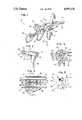
- FIG. 1is a perspective view of the handle section of a working element of a resectoscope incorporating features of the invention.
- FIG. 2is a perspective view of the electrical plug shown in FIG. 1
- FIG. 3is a cross-sectional side view of the guide block of FIG. 1 taken along lines 3--3.
- FIG. 4is a cross-sectional view of the guide block of FIG. 1 taken along lines 4--4 of FIG. 3.
- FIG. 5is a diagrammatical view of the guide block of FIG. 1 with the electrical plug in different orientations.
- FIG. 1there is shown a partial perspective view of the handle section of a resectoscope working element 10.
- the present inventionwill be described with reference to the working element 10 of FIG. 1, is should be understood that the present invention can be used with various different types of resectoscope working elements, including Iglesias type working elements and McCarthy type working elements, and can also be employed in any type of medical endoscope using an electrode.
- the elements of the present inventioncan have any suitable size, shape or type of material.
- Cross-referenceis hereby made to the following copending patent applications: "System For Disconnectably Mounting An Endoscope Sheath With An Endoscope Tool" by Grossi et al, Ser. No.
- the working element 10 shown in FIG. 1is generally known as a Baumrucker type working element.
- the handle section of the working elementgenerally comprises a frame 12, a handle 14, a thumb guide 16, a guide block 18, and an electrical plug 20 with a conductor 22.
- the working element 10also comprises a telescope sheath 24 and an electrode assembly sheath 26 that are insertable into a cooperating sheath (not shown).
- a telescope(not shown) may be inserted into an aperture 28 in the frame 12 which communicates with the telescope sheath 24 whereby the telescope can be inserted and retained in the telescope sheath 24.
- the frame 12also comprises, in this embodiment, a guide bar 30.
- the guide block 18 and handle 14, in this embodimentare slidingly mounted on a portion of the telescope sheath 24 and the guide bar 30.
- a spring 32biases the handle 14 and guide block 18 in a first forward direction.
- An operatorhaving his thumb in the thumb guide 16 and fingers on the handle 14 can move the handle 14 and guide block 18 in a rearward direction compressing the spring 32 and axially moving an electrode assembly 74 which is connected to the guide block 18.
- the electrical plug 20is connected inside the guide block 18 directly to a proximal region of the electrode assembly 74 such that electrosurgical current from an electrosurgical generator (not shown) can be transmitted via the conductor 22 and plug 20 directly to the electrode assembly to perform a desired operation.
- the plug 20generally comprises a housing 34 and an extension block 36.
- the housing 34 and extension block 36are comprised of a dielectric material and are molded as a single unit.
- the housing 34in this embodiment, is provided with a suitable shape such that an operator can readily grasp the housing for insertion or removal of the plug 20 from the guide block 18.
- the conductor 22is generally comprised of a center electrically conductive material such as copper or other suitable material and an outer protective covering of an insulative material.
- the extension block 36can generally be described as having a rectangular profile. However, the present invention may have the extension block with any suitable shape.
- the extension block 36has a leading face 38 having a slot 44 which extends into the extension block 36 between a first side 40 and a second side 42.
- the slot 44is generally centrally located relative to the leading face 38 and generally forms a top arm 46 and a bottom arm 48 in the extension block 36.
- Mounted in the extension block 36 proximate the slot 44is an electrical contact or connector 50 having a top portion 52 and a bottom portion 54.
- the electrical connector 50is connected to the conductor 22 in the housing 34.
- the guide block 18 of FIG. 1generally comprises a telescope sheath aperture 56, a guide bar aperture 58, and an electrode assembly proximal end aperture 60 and a plug receptacle or channel 62 having a first entry 64 on a first lateral side 66 of the guide block and a second entry 68 on a second lateral side 70 of the guide block.
- Suitable means 72 for retaining the proximal end of the electrode assembly 74are also provided with the guide block 18.
- the receptacle or channel 62generally extends entirely through the guide block 18 between the first entry 64 and second entry 68. In the embodiment shown, the receptacle or channel 62 generally intersects the electrode assembly proximal end aperture 60 at a substantially perpendicular angle.
- the shape of the receptacle or channel 62is generally rectangular such that the extension block 36 of the plug 20 can be matingly receiving therein.
- the guide block 18is made of a suitable material such as Teflon, a trademark of E. I. Dupont Co., which has high lubricity, low moisture absorption and a good dielectric strength.
- the extension block 36may be slightly tapered to provide easy insertion into the receptacle or channel 62 but nonetheless form a tight fit therewith.
- the proximal end of the electrode assembly 74generally passes through the slot 44 of the extension block 36 with the slot 44 being relatively centrally located relative thereto.
- the top portion 52 and bottom portion 54 of the contact 50make an electrical contact with the electrode assembly 74 such that electrosurgical current can be transmitted thereto.
- the present inventiongenerally provides for attaching the plug 20 to the guide block 18 at various different orientations and positions, but which nonetheless allow for an electrical contact with the electrode assembly 74.
- the plug 20can be connected to the electrode assembly 74 on either the first lateral side 66 or the second lateral side 70 of the guide block.
- the embodiment shown in FIG. 1allows for the plug 20 to be orientated in two orientations on each side.
- FIG. 4generally illustrates a first position of the plus 20 on the first side 66.
- the extension block 36extends from the housing 34 at a substantially right angle to the entry of the conductor 22 into the housing 34. At this first position the conductor 22 extends from the plug 20 in a substantially downwardly extending orientation.
- profile 76generally illustrates a second position that the plug 20 could have relative to the guide block 18.
- the conductor 22extends away from the housing 34 in a substantially upwardly extending position.
- Profile 78generally shows the plug 20 in a third position.
- This third positiongenerally consists of the plug 20 being mounted to the guide block 18 on the second side 70 with the conductor 22 being oriented in a downwardly extending position.
- Profile 80generally illustrates the plug 20 being in a forth position relative to the guide block 18. In this fourth position the plug 20 is connected to the guide block 18 on the second side 70 with the conductor 22 being orientated in a generally upwardly extending position.
- the connector 50will always make an electrical contact with the electrode assembly 74.
- this featureis provided by the located slot 44 being positioned in the receptacle or channel 62 at generally the same position at every orientation of the plug 20.
- the extension block 36 and at least a portion of the receptacle or channel 62have been provided with a generally rectangular profile.
- the feature of the rectangular profilelimits the number of orientations which the plug 20 can be connected to the guide block 18.
- the rectangular profilelimits the number of orientations to four; two on each side.
- the shape of the extension block and/or receptacle or channel 62 and/or an additional limiting meanscan be used to limit the orientations of the plug 20 to two; one on each side. Alternatively, any number or orientations can be provided on each side.
- the present inventionallows for the electrical plug 20 to be reoriented to accommodate different operators.
- a right handed operatorwould generally prefer to have the plug 20 on the first side 66 such that the plug 20 would not interfere with the operator's movement of the guide block 18 or unnecessarily hinder the operators quick and unencombered access to the working element with his left hand.
- a left handed operatorwould prefer to have the plug 20 on the second side 70 of the guide block 18 such that he could operate the working element 10 without being annoyed or hindered by the plug 20.
- the plug 20can be orientated with the conductor 22 extending either in an upwardly extending position or a downwardly extending position, this allows the operator to orientate the conductor 22 as he desires. For instance, many operators prefer to have the conductor 22 extend in an upwardly extending position wherein he could clamp the conductor overhead and would not feel comfortable or confident about the working element unless the conductor was so arranged. Oppositely, there are some operators who do not like the conductor to be extending overhead. They prefer instead to have the conductor extend downwardly to the floor and would not feel comfortable or confident about the working element unless the conductor was so arranged. Thus, the need arose for a working element that could have an electrical plug suitable for both right handed and left handed operators and which could nonetheless be orientated in either an upwardly or downwardly extending position.
- the present inventionprovides a solution to this problem.
- the guide blockmay be provided with a pinion channel having a first entry on the first side 66 of the guide block and a second entry on the second side 70 of the guide block.
- the pinioncan be provided such that it is removable from the pinion channel and can be inserted into either the first lateral side or the second lateral side to accommodate either a right handed user or a left handed user.
Landscapes
- Health & Medical Sciences (AREA)
- Surgery (AREA)
- Engineering & Computer Science (AREA)
- Life Sciences & Earth Sciences (AREA)
- Biomedical Technology (AREA)
- Otolaryngology (AREA)
- Nuclear Medicine, Radiotherapy & Molecular Imaging (AREA)
- Plasma & Fusion (AREA)
- Physics & Mathematics (AREA)
- Heart & Thoracic Surgery (AREA)
- Medical Informatics (AREA)
- Molecular Biology (AREA)
- Animal Behavior & Ethology (AREA)
- General Health & Medical Sciences (AREA)
- Public Health (AREA)
- Veterinary Medicine (AREA)
- Endoscopes (AREA)
Abstract
Description
Claims (4)
Priority Applications (2)
| Application Number | Priority Date | Filing Date | Title |
|---|---|---|---|
| US07/202,154US4919131A (en) | 1988-06-02 | 1988-06-02 | Resectoscope with improved guide block and electrical plug connection |
| US07/318,120US4917621A (en) | 1988-06-02 | 1989-03-02 | Resectoscope with improved guide block and electrical plug connection |
Applications Claiming Priority (1)
| Application Number | Priority Date | Filing Date | Title |
|---|---|---|---|
| US07/202,154US4919131A (en) | 1988-06-02 | 1988-06-02 | Resectoscope with improved guide block and electrical plug connection |
Related Child Applications (1)
| Application Number | Title | Priority Date | Filing Date |
|---|---|---|---|
| US07/318,120DivisionUS4917621A (en) | 1988-06-02 | 1989-03-02 | Resectoscope with improved guide block and electrical plug connection |
Publications (1)
| Publication Number | Publication Date |
|---|---|
| US4919131Atrue US4919131A (en) | 1990-04-24 |
Family
ID=22748702
Family Applications (1)
| Application Number | Title | Priority Date | Filing Date |
|---|---|---|---|
| US07/202,154Expired - LifetimeUS4919131A (en) | 1988-06-02 | 1988-06-02 | Resectoscope with improved guide block and electrical plug connection |
Country Status (1)
| Country | Link |
|---|---|
| US (1) | US4919131A (en) |
Cited By (17)
| Publication number | Priority date | Publication date | Assignee | Title |
|---|---|---|---|---|
| US5007908A (en)* | 1989-09-29 | 1991-04-16 | Everest Medical Corporation | Electrosurgical instrument having needle cutting electrode and spot-coag electrode |
| US5423813A (en)* | 1993-03-18 | 1995-06-13 | Coopersurgical | Resectoscope and electrode assembly |
| US5486155A (en)* | 1994-07-15 | 1996-01-23 | Circon Corporation | Rotatable endoscope sheath |
| US5857962A (en)* | 1997-03-13 | 1999-01-12 | Circon Corporation | Resectoscope with curved electrode channel and resiliently deflectable electrode section |
| US5919191A (en)* | 1995-01-30 | 1999-07-06 | Boston Scientific Corporation | Electro-surgical tissue removal |
| DE10042097C1 (en)* | 2000-08-26 | 2001-12-20 | Winter & Ibe Olympus | Urological resectoscope for prostate surgery has proximal end of electrode carrier secured and electrically contacted within sliding body |
| DE10042095C1 (en)* | 2000-08-26 | 2002-01-17 | Winter & Ibe Olympus | Urological rectoscope has sliding body provided with transverse bore for 2-part clamp block for electrode carrier for HF electrode |
| DE10042096C1 (en)* | 2000-08-26 | 2002-01-24 | Winter & Ibe Olympus | Monopolar and bipolar electrodes for urological resectoscope includes fastening section close to first contact section |
| WO2002017807A1 (en) | 2000-08-26 | 2002-03-07 | Olympus Winter & Ibe Gmbh | Monopolar and bipolar electrode for a urological resectoscope |
| US6494881B1 (en) | 1997-09-30 | 2002-12-17 | Scimed Life Systems, Inc. | Apparatus and method for electrode-surgical tissue removal having a selectively insulated electrode |
| WO2003013378A1 (en)* | 2001-08-10 | 2003-02-20 | Olympus Winter & Ibe Gmbh | Electrode for use in urological resectoscopes |
| US20030149442A1 (en)* | 2002-02-04 | 2003-08-07 | Gellman Barry N. | Resistance heated tissue morcellation |
| US20060058580A1 (en)* | 2004-09-16 | 2006-03-16 | Olympus Winter & Ibe Gmbh | Resectoscope electrode that is longitudinally displaced by a carriage |
| DE102011107783A1 (en) | 2011-07-15 | 2013-01-17 | Olympus Winter & Ibe Gmbh | Bipolar resectoscope and slides and cables for it |
| DE102012023275A1 (en) | 2012-07-12 | 2014-01-16 | Olympus Winter & Ibe Gmbh | resectoscope |
| DE102012013735A1 (en) | 2012-07-12 | 2014-01-16 | Olympus Winter & Ibe Gmbh | Resectoscope for cutting prostate tissue from urethra in urology field, has body and shaft designed so that body is rotated in position reached at end of insertion movement in end position, in which body is locked by shaft against movement |
| US20230011205A1 (en)* | 2021-06-08 | 2023-01-12 | Olympus Winter & Ibe Gmbh | Electrosurgical handheld device, and contact body for an electrosurgical handheld device |
Citations (15)
| Publication number | Priority date | Publication date | Assignee | Title |
|---|---|---|---|---|
| US2090923A (en)* | 1937-08-24 | Electrodic endoscopic instrtjment | ||
| US2249894A (en)* | 1938-12-19 | 1941-07-22 | Goldenstein Bernardo | Universal electrode holder for diathermic applications |
| US2487502A (en)* | 1945-09-26 | 1949-11-08 | American Cystoscope Makers Inc | Instrument for electrosurgical resection |
| US2545865A (en)* | 1948-05-11 | 1951-03-20 | American Cystoscope Makers Inc | Electrosurgical instrument |
| FR1548389A (en)* | 1967-08-09 | 1968-12-06 | ||
| US3847153A (en)* | 1973-09-14 | 1974-11-12 | B Weissman | Disposable probe tip for electro-surgical device |
| US3850162A (en)* | 1972-07-03 | 1974-11-26 | J Iglesias | Endoscope with continuous irrigation |
| US4132227A (en)* | 1974-08-08 | 1979-01-02 | Winter & Ibe | Urological endoscope particularly resectoscope |
| US4149538A (en)* | 1977-08-15 | 1979-04-17 | American Hospital Supply Corporation | Resectoscope electrode assembly with non-conductive bearing tube and method of making the same |
| USD251609S (en) | 1977-02-09 | 1979-04-17 | American Hospital Supply Corporation | Handle for urological instrument |
| USD251608S (en) | 1977-02-09 | 1979-04-17 | American Hospital Supply Corporation | Operating handle for urological instrument |
| US4326530A (en)* | 1980-03-05 | 1982-04-27 | Fleury Jr George J | Surgical snare |
| US4538610A (en)* | 1982-01-14 | 1985-09-03 | Olympus Optical Co., Ltd. | Resectoscope |
| US4726370A (en)* | 1985-02-09 | 1988-02-23 | Olympus Optical Co., Ltd. | Resectoscope device |
| US4732149A (en)* | 1985-01-22 | 1988-03-22 | Hermann Sutter | Bipolar medical coagulation instrument |
- 1988
- 1988-06-02USUS07/202,154patent/US4919131A/ennot_activeExpired - Lifetime
Patent Citations (15)
| Publication number | Priority date | Publication date | Assignee | Title |
|---|---|---|---|---|
| US2090923A (en)* | 1937-08-24 | Electrodic endoscopic instrtjment | ||
| US2249894A (en)* | 1938-12-19 | 1941-07-22 | Goldenstein Bernardo | Universal electrode holder for diathermic applications |
| US2487502A (en)* | 1945-09-26 | 1949-11-08 | American Cystoscope Makers Inc | Instrument for electrosurgical resection |
| US2545865A (en)* | 1948-05-11 | 1951-03-20 | American Cystoscope Makers Inc | Electrosurgical instrument |
| FR1548389A (en)* | 1967-08-09 | 1968-12-06 | ||
| US3850162A (en)* | 1972-07-03 | 1974-11-26 | J Iglesias | Endoscope with continuous irrigation |
| US3847153A (en)* | 1973-09-14 | 1974-11-12 | B Weissman | Disposable probe tip for electro-surgical device |
| US4132227A (en)* | 1974-08-08 | 1979-01-02 | Winter & Ibe | Urological endoscope particularly resectoscope |
| USD251609S (en) | 1977-02-09 | 1979-04-17 | American Hospital Supply Corporation | Handle for urological instrument |
| USD251608S (en) | 1977-02-09 | 1979-04-17 | American Hospital Supply Corporation | Operating handle for urological instrument |
| US4149538A (en)* | 1977-08-15 | 1979-04-17 | American Hospital Supply Corporation | Resectoscope electrode assembly with non-conductive bearing tube and method of making the same |
| US4326530A (en)* | 1980-03-05 | 1982-04-27 | Fleury Jr George J | Surgical snare |
| US4538610A (en)* | 1982-01-14 | 1985-09-03 | Olympus Optical Co., Ltd. | Resectoscope |
| US4732149A (en)* | 1985-01-22 | 1988-03-22 | Hermann Sutter | Bipolar medical coagulation instrument |
| US4726370A (en)* | 1985-02-09 | 1988-02-23 | Olympus Optical Co., Ltd. | Resectoscope device |
Non-Patent Citations (9)
| Title |
|---|
| "ACMI Adult Resectoscope Operating & Maintenance Manual", American ACMI, June 1984. |
| "ACMI Adult Resectoscope Operating and Maintenance Manual", American ACMI, June 1984. |
| "ACMI Continuous Flow Resectoscope", Jan. 1987. |
| "Operating and Maintenance Manual Continuous Flow Resectoscope", American ACMI, Apr. 1983. |
| ACMI Adult Resectoscope Operating & Maintenance Manual , American ACMI, June 1984.* |
| ACMI Adult Resectoscope Operating and Maintenance Manual , American ACMI, June 1984.* |
| ACMI Continuous Flow Resectoscope , Jan. 1987.* |
| Operating and Maintenance Manual Continuous Flow Resectoscope , American ACMI, Apr. 1983.* |
| The New Continuous Flow Resectoscope from American ACMI, May 1984.* |
Cited By (37)
| Publication number | Priority date | Publication date | Assignee | Title |
|---|---|---|---|---|
| US5007908A (en)* | 1989-09-29 | 1991-04-16 | Everest Medical Corporation | Electrosurgical instrument having needle cutting electrode and spot-coag electrode |
| US5423813A (en)* | 1993-03-18 | 1995-06-13 | Coopersurgical | Resectoscope and electrode assembly |
| US5486155A (en)* | 1994-07-15 | 1996-01-23 | Circon Corporation | Rotatable endoscope sheath |
| US5919191A (en)* | 1995-01-30 | 1999-07-06 | Boston Scientific Corporation | Electro-surgical tissue removal |
| US5857962A (en)* | 1997-03-13 | 1999-01-12 | Circon Corporation | Resectoscope with curved electrode channel and resiliently deflectable electrode section |
| US6494881B1 (en) | 1997-09-30 | 2002-12-17 | Scimed Life Systems, Inc. | Apparatus and method for electrode-surgical tissue removal having a selectively insulated electrode |
| US6827717B2 (en) | 2000-08-26 | 2004-12-07 | Olympus Winter & Ibe Gmbh | Monopolar and bipolar electrode for a urological resectoscope |
| US20030144661A1 (en)* | 2000-08-26 | 2003-07-31 | Pieter Brommersma | Urological electrosurgical resectoscope |
| WO2002017808A1 (en) | 2000-08-26 | 2002-03-07 | Olympus Winter & Ibe Gmbh | Urological electrosurgical resectoscope |
| WO2002017807A1 (en) | 2000-08-26 | 2002-03-07 | Olympus Winter & Ibe Gmbh | Monopolar and bipolar electrode for a urological resectoscope |
| WO2002017806A1 (en)* | 2000-08-26 | 2002-03-07 | Olympus Winter & Ibe Gmbh | Urological resectoscope comprising a contacting device |
| DE10042095C1 (en)* | 2000-08-26 | 2002-01-17 | Winter & Ibe Olympus | Urological rectoscope has sliding body provided with transverse bore for 2-part clamp block for electrode carrier for HF electrode |
| DE10042097C1 (en)* | 2000-08-26 | 2001-12-20 | Winter & Ibe Olympus | Urological resectoscope for prostate surgery has proximal end of electrode carrier secured and electrically contacted within sliding body |
| US6893441B2 (en) | 2000-08-26 | 2005-05-17 | Olympus Winter & Ibe Gmbh | Urological electrosurgical resectoscope |
| DE10042096C1 (en)* | 2000-08-26 | 2002-01-24 | Winter & Ibe Olympus | Monopolar and bipolar electrodes for urological resectoscope includes fastening section close to first contact section |
| US20040044343A1 (en)* | 2000-08-26 | 2004-03-04 | Pieter Brommersma | Monopolar and bipolar electrode for a urological resectoscope |
| US6746395B2 (en) | 2000-08-26 | 2004-06-08 | Olympus Winter & Ibe Gmbh | Urological resectoscope comprising a contacting device |
| GB2394422A (en)* | 2001-08-10 | 2004-04-28 | Winter & Ibe Olympus | Electrode for use in urological resectoscopes |
| WO2003013378A1 (en)* | 2001-08-10 | 2003-02-20 | Olympus Winter & Ibe Gmbh | Electrode for use in urological resectoscopes |
| US20050010080A1 (en)* | 2001-08-10 | 2005-01-13 | Jorg Dickopp | Electrode for use in urological resectoscopes |
| GB2394422B (en)* | 2001-08-10 | 2005-02-16 | Winter & Ibe Olympus | Electrode for use in urological resectoscopes |
| US20030149442A1 (en)* | 2002-02-04 | 2003-08-07 | Gellman Barry N. | Resistance heated tissue morcellation |
| US6997926B2 (en) | 2002-02-04 | 2006-02-14 | Boston Scientific Scimed, Inc. | Resistance heated tissue morcellation |
| DE102004045337B4 (en) | 2004-09-16 | 2018-09-13 | Olympus Winter & Ibe Gmbh | Resectoscope with a longitudinally displaceable electrode |
| US20060058580A1 (en)* | 2004-09-16 | 2006-03-16 | Olympus Winter & Ibe Gmbh | Resectoscope electrode that is longitudinally displaced by a carriage |
| DE102004045337A1 (en) | 2004-09-16 | 2006-04-06 | Olympus Winter & Ibe Gmbh | Resectoscope with a longitudinally displaceable electrode |
| DE102004045337B9 (en) | 2004-09-16 | 2018-12-13 | Olympus Winter & Ibe Gmbh | Resectoscope with a longitudinally displaceable electrode |
| DE102011107783A1 (en) | 2011-07-15 | 2013-01-17 | Olympus Winter & Ibe Gmbh | Bipolar resectoscope and slides and cables for it |
| WO2013010602A1 (en) | 2011-07-15 | 2013-01-24 | Olympus Winter & Ibe Gmbh | Bipolar resectoscope and carriage and cable therefor |
| DE102011107783B4 (en) | 2011-07-15 | 2023-02-23 | Olympus Winter & Ibe Gmbh | Bipolar resectoscope and carriage and cable therefor |
| US20140018799A1 (en)* | 2012-07-12 | 2014-01-16 | Olympus Winter & Ibe Gmbh | Resectoscope |
| CN103536354B (en)* | 2012-07-12 | 2016-03-02 | 奥林匹斯冬季和Ibe有限公司 | Resectoscope |
| US9486277B2 (en)* | 2012-07-12 | 2016-11-08 | Olympus Winter & Ibe Gmbh | Resectoscope |
| CN103536354A (en)* | 2012-07-12 | 2014-01-29 | 奥林匹斯冬季和Ibe有限公司 | Resectoscope |
| DE102012013735A1 (en) | 2012-07-12 | 2014-01-16 | Olympus Winter & Ibe Gmbh | Resectoscope for cutting prostate tissue from urethra in urology field, has body and shaft designed so that body is rotated in position reached at end of insertion movement in end position, in which body is locked by shaft against movement |
| DE102012023275A1 (en) | 2012-07-12 | 2014-01-16 | Olympus Winter & Ibe Gmbh | resectoscope |
| US20230011205A1 (en)* | 2021-06-08 | 2023-01-12 | Olympus Winter & Ibe Gmbh | Electrosurgical handheld device, and contact body for an electrosurgical handheld device |
Similar Documents
| Publication | Publication Date | Title |
|---|---|---|
| US4919131A (en) | Resectoscope with improved guide block and electrical plug connection | |
| US4917082A (en) | Resectoscope electrode | |
| US6827717B2 (en) | Monopolar and bipolar electrode for a urological resectoscope | |
| US7347860B2 (en) | Endoscope for high-frequency treatment | |
| US4112950A (en) | Medical electronic apparatus and components | |
| US20080033237A1 (en) | High-frequency tool for endoscope | |
| US5413575A (en) | Multifunction electrocautery tool | |
| US4655215A (en) | Hand control for electrosurgical electrodes | |
| US7326209B2 (en) | Bipolar high frequency treatment tool for endoscope | |
| US4892105A (en) | Electrical stimulus probe | |
| US7276066B2 (en) | Medical instrument for endoscope | |
| US4917621A (en) | Resectoscope with improved guide block and electrical plug connection | |
| US5246440A (en) | Electrosurgical knife | |
| US6214001B1 (en) | Electrocauterizing tool for orthopedic shave devices | |
| US6893441B2 (en) | Urological electrosurgical resectoscope | |
| US6969389B2 (en) | Bipolar hemostatic forceps for an endoscope | |
| US5857962A (en) | Resectoscope with curved electrode channel and resiliently deflectable electrode section | |
| DE502268T1 (en) | ELECTROSURGICAL INSTRUMENT WITH A NEEDLE ELECTRODE FOR CUTTING AND A POINT ELECTRODE FOR COAGULATION. | |
| JPH01195850A (en) | Freely extensible type electric knife surgical apparatus and method | |
| US2545865A (en) | Electrosurgical instrument | |
| CA2039088A1 (en) | Polypectome snare with bipolar electrodes | |
| US20050267469A1 (en) | Bipolar medical instrument and electrosurgical system comprising such an instrument | |
| US20060206112A1 (en) | Instrument for cutting living tissue | |
| EP2749312B1 (en) | Catheter connector | |
| US6974458B2 (en) | Medical device with improved power plug connection |
Legal Events
| Date | Code | Title | Description |
|---|---|---|---|
| AS | Assignment | Owner name:CIRCON CORPORATION, 749 WARD DRIVE, SANTA BARBARA, Free format text:ASSIGNMENT OF ASSIGNORS INTEREST.;ASSIGNORS:GROSSI, BENEDETTO;BRACCI, THOMAS W.;REEL/FRAME:004886/0865 Effective date:19880601 Owner name:CIRCON CORPORATION,CALIFORNIA Free format text:ASSIGNMENT OF ASSIGNORS INTEREST;ASSIGNORS:GROSSI, BENEDETTO;BRACCI, THOMAS W.;REEL/FRAME:004886/0865 Effective date:19880601 | |
| STCF | Information on status: patent grant | Free format text:PATENTED CASE | |
| FEPP | Fee payment procedure | Free format text:PAYOR NUMBER ASSIGNED (ORIGINAL EVENT CODE: ASPN); ENTITY STATUS OF PATENT OWNER: LARGE ENTITY | |
| FPAY | Fee payment | Year of fee payment:4 | |
| FPAY | Fee payment | Year of fee payment:8 | |
| AS | Assignment | Owner name:CHASE MANHATTAN BANK, THE, AS COLLATERAL AGENT, NE Free format text:SECURITY AGREEMENT;ASSIGNOR:CIRCON CORPORATION;REEL/FRAME:011122/0530 Effective date:19991112 | |
| FPAY | Fee payment | Year of fee payment:12 | |
| AS | Assignment | Owner name:ACMI CORPORATION, MASSACHUSETTS Free format text:CHANGE OF NAME;ASSIGNOR:CIRCON CORPORATION;REEL/FRAME:013295/0416 Effective date:20011227 | |
| AS | Assignment | Owner name:ANTARES CAPITAL CORPORATION, AS AGENT, ILLINOIS Free format text:SECURITY INTEREST;ASSIGNOR:ACMI CORPORATION;REEL/FRAME:014815/0179 Effective date:20031219 Owner name:CIRCON CORPORATION, MASSACHUSETTS Free format text:RELEASE BY SECURED PARTY;ASSIGNOR:JPMORGAN CHASE BANK, AS COLLATERAL AGENT (F/K/A THE CHASE MANHATTAN BANK);REEL/FRAME:015592/0392 Effective date:20031219 | |
| AS | Assignment | Owner name:ACMI CORPORATION, MASSACHUSETTS Free format text:RELASE OF SECURITY AGREEMENT;ASSIGNOR:ANTARES CAPITAL CORPORATION;REEL/FRAME:016309/0574 Effective date:20050721 | |
| AS | Assignment | Owner name:THE GOVERNOR AND COMPANY OF THE BANK OF SCOTLAND, Free format text:SECURITY AGREEMENT;ASSIGNOR:ACMI CORPORATION;REEL/FRAME:016418/0218 Effective date:20050804 | |
| AS | Assignment | Owner name:GYRUS ACMI, INC., MASSACHUSETTS Free format text:ASSIGNMENT OF ASSIGNORS INTEREST;ASSIGNOR:BANK OF SCOTLAND;REEL/FRAME:030422/0113 Effective date:20130419 |