US4919039A - Hydraulic turning gear - Google Patents
Hydraulic turning gearDownload PDFInfo
- Publication number
- US4919039A US4919039AUS07/223,850US22385088AUS4919039AUS 4919039 AUS4919039 AUS 4919039AUS 22385088 AUS22385088 AUS 22385088AUS 4919039 AUS4919039 AUS 4919039A
- Authority
- US
- United States
- Prior art keywords
- pawl
- hydraulic
- ratchet wheel
- cylinder
- turning gear
- Prior art date
- Legal status (The legal status is an assumption and is not a legal conclusion. Google has not performed a legal analysis and makes no representation as to the accuracy of the status listed.)
- Expired - Fee Related
Links
- 239000012530fluidSubstances0.000claimsabstractdescription63
- 230000007246mechanismEffects0.000claimsabstractdescription45
- 238000001816coolingMethods0.000abstract1
- 238000010438heat treatmentMethods0.000abstract1
- 239000003921oilSubstances0.000description10
- 238000010276constructionMethods0.000description2
- 230000004048modificationEffects0.000description2
- 238000012986modificationMethods0.000description2
- 230000008859changeEffects0.000description1
- 238000010586diagramMethods0.000description1
- 230000005611electricityEffects0.000description1
- 239000012208gear oilSubstances0.000description1
- 238000005461lubricationMethods0.000description1
- 238000004064recyclingMethods0.000description1
Images


Classifications
- F—MECHANICAL ENGINEERING; LIGHTING; HEATING; WEAPONS; BLASTING
- F15—FLUID-PRESSURE ACTUATORS; HYDRAULICS OR PNEUMATICS IN GENERAL
- F15B—SYSTEMS ACTING BY MEANS OF FLUIDS IN GENERAL; FLUID-PRESSURE ACTUATORS, e.g. SERVOMOTORS; DETAILS OF FLUID-PRESSURE SYSTEMS, NOT OTHERWISE PROVIDED FOR
- F15B15/00—Fluid-actuated devices for displacing a member from one position to another; Gearing associated therewith
- F15B15/02—Mechanical layout characterised by the means for converting the movement of the fluid-actuated element into movement of the finally-operated member
- F15B15/06—Mechanical layout characterised by the means for converting the movement of the fluid-actuated element into movement of the finally-operated member for mechanically converting rectilinear movement into non- rectilinear movement
- F15B15/061—Mechanical layout characterised by the means for converting the movement of the fluid-actuated element into movement of the finally-operated member for mechanically converting rectilinear movement into non- rectilinear movement by unidirectional means
- Y—GENERAL TAGGING OF NEW TECHNOLOGICAL DEVELOPMENTS; GENERAL TAGGING OF CROSS-SECTIONAL TECHNOLOGIES SPANNING OVER SEVERAL SECTIONS OF THE IPC; TECHNICAL SUBJECTS COVERED BY FORMER USPC CROSS-REFERENCE ART COLLECTIONS [XRACs] AND DIGESTS
- Y10—TECHNICAL SUBJECTS COVERED BY FORMER USPC
- Y10T—TECHNICAL SUBJECTS COVERED BY FORMER US CLASSIFICATION
- Y10T74/00—Machine element or mechanism
- Y10T74/21—Elements
- Y10T74/2133—Pawls and ratchets
- Y10T74/2141—Sliding pawls
Definitions
- This inventionrelates, in general, to rotating turbomachines and to turning gears for rotating a turbine rotor when motive fluid is insufficient to cause the rotation of the turbine rotor.
- this inventionfurther relates to a hydraulic system and associated turning gear which is reduced in size for shipboard applications and which utilizes low pressure hydraulic fluid in combination with pressure boost means to provide sufficient turning power despite the reduced size of the equipment.
- Rotating machinerysuch as turbines, including steam turbines or gas turbines, require means associated with the rotating machinery to turn the turbine rotor whenever the motive fluid, steam or gas, is insufficient to cause the rotor to turn but while the rotor is at an elevated temperature such as during periods of warm-up, cool-down or if the supply of motive fluid is shutdown for some reason.
- the reason for utilizing a turning gear on a heated rotoris that if the rotor is not turned under these conditions it will develop or bow or sag as thermal conditions change which could result in the turbomachine being rendered inoperative.
- Another means for rotating a turbomachinery rotoris through the use of a hydraulic turning gear wherein hydraulic fluid is used to drive a hydraulic cylinder which, in turn, drives a ratchet and pawl mechanism for turning the turnbomachine rotor.
- This type of apparatusis generally smaller, lighter weight, able to function by means of a handpump or manual valve control for emergency operation and less expensive.
- the size of the hydraulic equipmenthas also been caused to increase. For example, one main piece of equipment in the hydraulic turning gear system which must be placed in the vicinity of the turning gear is the hydraulic cylinder.
- the size of the hydraulic cylindermay be reduced to a two inch diameter hydraulic cylinder if the pressure of the hydraulic fluid to the driving side of the hydraulic cylinder is raised after it has been withdrawn from a common reservoir.
- the reservoiris remotely located with respect to the hydraulic cylinder and therefore does not add to the size requirements of the turbine equipment envelope and by reducing the size of the hydraulic cylinder makes the turning gear apparatus more fittable into the turbine environment.
- a booster cylinderprovides a desirable means for raising the pressure of the hydraulic fluid prior to the introduction of the fluid into the hydraulic cylinder of reduced size.
- the hydraulic cylindermotivates a ratchet and pawl mechanism for turning the turning gear wheel.
- a ratchet and pawl mechanismfor turning the turning gear wheel.
- the disadvantage of a spring return for the pawlis the noise it may create as it hits after each tooth.
- the pawl of the present inventionutilizes frictional force to withhold the pawl from the ratchet wheel and then uses a positively driven reset to realign the pawl with the ratchet wheel thus obviating the use of a noise producing spring.
- a hydraulic turning gearcomprises a ratchet wheel attached to a turbomachine rotor and a pawl mechanism for driving the ratchet wheel and turbomachine rotor.
- the pawl mechanismis attached to the reciprocating arm of a hydraulic cylinder which is driven by a high pressure fluid.
- the high pressure fluidis supplied from an inline booster pump.
- the stroke of the hydraulic cylinderis controlled by a spool valve the position of which is set by a timer driven solenoid.
- the pawl mechanismis improved by a construction which provides a frictional force to withhold the pawl itself from the ratchet wheel as it disengages at the top of the hydraulic cylinder stroke and then allows the pawl to be reset or realigned by means of a guide rail contacted at the bottom of the hydraulic cylinder stroke.
- FIG. 1is a schematic drawing of a hydraulic turning gear.
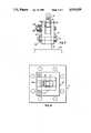
- FIG. 2is a side elevation view of the ratchet wheel and pawl mechanism.
- FIG. 3is an end view of the pawl mechanism.
- FIG. 4is a plan view of the pawl mechanism.
- FIG. 1is a schematic diagram of a hydraulic turning gear which includes a ratchet wheel 13 which may be attached to one end of a turbine rotor (not shown).
- the ratchet wheelmay be fitted to a stub shaft of a turbine by means of shrink fitting or by mechanical means.
- the turbinecould be a steam turbine which is part of a ship's service turbine/generator power plant which supplies electricity aboard a ship.
- a pawl mechanism 15drives the ratchet wheel 13.
- the pawl mechanismis driven in a reciprocal movement by a hydraulic cylinder 17 to which it it attached.
- the reciprocal movement of the pawl mechanismimparts rotational movement to the ratchet wheel and the turbine rotor shaft to which it is attached.
- the hydraulic cylindermay include a piston 19 which has a piston rod or extended arm 21 which extends through one end of the hydraulic cylinder which is closest to the pawl mechanism 15.
- the piston rod or arm 21itself is connected to the pawl mechanism in a manner yet to be described.
- the hydraulic cylinder 17is connected at its high pressure side (HP) to high pressure fluid line 31 which drives the piston 19 toward the ratchet wheel 13 which causes it to rotate.
- the hydraulic cylinder 17is connected at its low pressure side (LP) to a low pressure fluid line 25 which drives piston 19 away from the ratchet wheel during disengagement. Since the fluid in line 25 acts only against the piston 19 when the high pressure side is draining, the fluid in line 25 may be low pressure fluid.
- a coil springmay be used to drive the piston away from the ratchet.
- Relatively low pressure oilat about 100 psi, is supplied as indicated on line 35.
- the low pressure oilis obtained from a common oil reservoir which may also contain control oil.
- the oilis admitted to a two position, four-way pilot or solenoid valve 37 through inlet line 39 and expelled to drain through a discharge line 41.
- the position of the solenoid valve 37controls the flow of fluid to a directional spool valve 43.
- fluid on line 39is passed through the "a" side of solenoid valve 37 which causes it to position spool valve 39 in its corresponding position "A". This is caused by the flow of fluid in control line 47 as indicated by the dashed line.
- Thisallows low pressure fluid from line 35 to be passed through spool valve 43 into line 45. It also allows fluid within line 55 to be connected to drain.
- Solenoid valve 37is connected to a timer 49 which may be actuated by a start switch 51 and powered from an electrical source 53.
- the timerwill cause the solenoid to cycle from position “a” to position “b” as required by the rotor conditions and programmed into the timer.
- control fluid in line 47is connected to drain and control fluid in line 59 is connected to the low pressure fluid supply.
- Thiscauses spool valve 43 to be shifted to position "B” which then connects line 55 to low pressure fluid line 35 and line 45 to drain. Lines 45 and 55 are connected to a hydraulic booster cylinder 65.
- the hydraulic booster cylinderincludes a piston 67 which is caused to reciprocate by the admission and draining of fluid from the booster cylinder.
- the booster cylinderincludes a large diameter cylinder 65a and a small diameter cylinder 65b whereas the piston 67 includes a large diameter piston head 67a which drives a piston rod or ram 67b which extends into the small diameter cylinder 65b.
- fluid in line 71is also input through spring loaded check valve 72 into smaller cylinder 65b ahead of the ram 67b. Fluid is also admitted into the booster cylinder behind the piston head 67 through line 55.
- the operation of the booster cylinderis readily apparent from its construction as shown in FIG. 1.
- Fluid in line 45is used to push the piston to the right while it also is filling the small diameter cylinder 65b through line 71 and check valve 72.
- spool valve 43is in poisition "A" with parallel internal fluid lines so that fluid is input into line 45 whereas line 55 is connected to drain.
- spool valve 43is in its "B” connection having crossed fluid lines whereby line 55 is connected to the fluid supply and line 45 is connected to drain.
- the fluid in the small diameter cylinder 65bis pressurized to about 1900 psi from about 100 psi and it charges line 31.
- the hydraulic boost cylinderallows the use of hydraulic fluid at relatively low oil pressure such as is used for hydraulic control functions to be used to drive the turning gear without enlarging the hydraulic cylinder located in the area ratchet whell and the turbomachine.
- the inventionfurther saves weight which might be attributable to a larger hydraulic cylinder and a separate oil tank to hold turning gear oil.
- the hydraulic boost cylindermay be placed wherever it is convenient rather than being required adjacent the turbine rotor.
- the ratchet wheel 13includes a plurality of circumferentially mounted ratchet teeth 75 which generally include a step portion 77 and a riser portion 79.
- the pawl mechanism 15pushes against the riser portion of the of a ratchet tooth and pushes the wheel in a counterclockwise direction.
- the pawl mechanism 15includes a pawl 115 and a sawcut clevis 117.
- the clevisis mounted on the extended arm or piston rod 21 of the hydraulic cylinder which is driven by the piston 19 in the hydraulic cylinder.
- a nut 119 and bolt 121removably fasten the clevis to the hydraulic cylinder arm.
- the pawl 115is mounted to the clevis 117 so that it will pivot around the pin 125.
- Stacked Belleville washers 127provide and adjustable force applied to the clevis which in conjunction with the friction washer 129 provides a frictional forcr on the pawl 115 which prevents it from rotating back, on its own, toward the ratchet wheel once it is pushed away from the ratchet wheel by teeth 75.
- Locking nut 126retains the Belleville washers on the pin 125.
- Guide rail 135is mounted to a cylinder mount plate 137 which is part of the hydraulic cylinder 17.
- the clevisis guided by the guide rail 135 as it reciprocates toward and away from the ratchet wheel.
- An "L" shaped tang 141is mounted on the pawl 115 and as the pawl is rotated, by the ratchet wheel away from the wheel, it will contact a stop pin 143. However, as the pawl mechanism is further withdrawn away from the ratchet wheel the tange on the pawl will contact the guide rail 135 at land 145 to cause the pawl to become realigned for the next stroke of the hydraulic cylinder.
- a hydraulic turning gearincludes a ratchet wheel 13 and a pawl mechanism 15 for rotating a turbine rotor (not shown).
- the pawl mechanismis caused to move in a reciprocating manner by a hydraulic cylinder 17 which is alternately filled and then drained.
- the hydraulic cylinderis reduced in size because of the high pressure hydraulic fluid which is received from a boost hydraulic cylinder 65.
- the boost hydraulic cylinderis also caused to cycle in a reciprocating manner due to a spool valve 43 which inputs relatively low pressure hydraulic fluid into the booster cylinder.
- the spool valvehas two positions which are set by a solenoid valve 37 responding to a timer 49.
- the inventionallows the utilization of low pressure fluid to drive higher power turning gears without a penalty in weight or larger envelope requirements.
- the pawl mechanism 15is developed for use with the hydraulic turning gear just described and includes a Belleville spring 127 and friction washer 129 for retaining the pawl 115 itself within the clevis 117 so that once the pawl is pushed away from the ratchet wheel it will remain withdrawn until it can be reset by means of guide rail 135 which bears against tang 141 as the pawl mechanism reaches the furthest point away from the ratchet wheel before recycling back toward the ratchet wheel. In this way, the pawl is positively reset rather than depending on a return spring.
Landscapes
- Engineering & Computer Science (AREA)
- Physics & Mathematics (AREA)
- Fluid Mechanics (AREA)
- Mechanical Engineering (AREA)
- General Engineering & Computer Science (AREA)
- Transmission Devices (AREA)
Abstract
Description
This invention was made in the course of Government Contract No. N00024-83-C-4181 (Prime) and N3352-766 (Subcontract) for the United States Navy and rights to the invention are determined by the provisions in those contracts.
This invention relates, in general, to rotating turbomachines and to turning gears for rotating a turbine rotor when motive fluid is insufficient to cause the rotation of the turbine rotor. In particular, this invention further relates to a hydraulic system and associated turning gear which is reduced in size for shipboard applications and which utilizes low pressure hydraulic fluid in combination with pressure boost means to provide sufficient turning power despite the reduced size of the equipment.
Rotating machinery such as turbines, including steam turbines or gas turbines, require means associated with the rotating machinery to turn the turbine rotor whenever the motive fluid, steam or gas, is insufficient to cause the rotor to turn but while the rotor is at an elevated temperature such as during periods of warm-up, cool-down or if the supply of motive fluid is shutdown for some reason. The reason for utilizing a turning gear on a heated rotor is that if the rotor is not turned under these conditions it will develop or bow or sag as thermal conditions change which could result in the turbomachine being rendered inoperative.
One way of rotating a turning gear in through the use of an electric motor which is coupled to the rotor. However, in this arrangement, the motor must be located adjacent the turbine rotor and as the power requirements for rotating the turbomachine rotor increase the size of the motor must also increase such that it has been found difficult to meet the envelope requirements of the turbine environment. Also, with the increase in size of the motor there is also an increase in weight which is an undesirable characteristic in modern ship power plants. Another compromising feature of electric motors used as turning gear drivers occurs under complete loss of power conditions where the turbomachine rotor could be severely endangered if rotation is not effected.
Another means for rotating a turbomachinery rotor is through the use of a hydraulic turning gear wherein hydraulic fluid is used to drive a hydraulic cylinder which, in turn, drives a ratchet and pawl mechanism for turning the turnbomachine rotor. This type of apparatus is generally smaller, lighter weight, able to function by means of a handpump or manual valve control for emergency operation and less expensive. However, as power requirements for rotating the turning gear have increased, the size of the hydraulic equipment has also been caused to increase. For example, one main piece of equipment in the hydraulic turning gear system which must be placed in the vicinity of the turning gear is the hydraulic cylinder. Using low pressure oil (100 psi) as the driving fluid would result in a ten inch diameter hydraulic cylinder in a very crowded space near the turbine equipment. The low pressure hydraulic fluid is preferred since it is also used for lubrication fluid therefore allowing the use of a single fluid supply. In one aspect of this invention it has been found that the size of the hydraulic cylinder may be reduced to a two inch diameter hydraulic cylinder if the pressure of the hydraulic fluid to the driving side of the hydraulic cylinder is raised after it has been withdrawn from a common reservoir. The reservoir is remotely located with respect to the hydraulic cylinder and therefore does not add to the size requirements of the turbine equipment envelope and by reducing the size of the hydraulic cylinder makes the turning gear apparatus more fittable into the turbine environment.
A booster cylinder provides a desirable means for raising the pressure of the hydraulic fluid prior to the introduction of the fluid into the hydraulic cylinder of reduced size.
The hydraulic cylinder motivates a ratchet and pawl mechanism for turning the turning gear wheel. Realizing that this means that the pawl which engages the ratchet wheel must pivot to engage and disengage from the ratchet wheel several times in each shaft revolution, the disadvantage of a spring return for the pawl is the noise it may create as it hits after each tooth. According to another feature of the present invention, the pawl of the present invention utilizes frictional force to withhold the pawl from the ratchet wheel and then uses a positively driven reset to realign the pawl with the ratchet wheel thus obviating the use of a noise producing spring.
It is therefore an object of the present invention to provide a hydraulic turning gear which provides an elevated pressure fluid to a hydraulic cylinder of reduced size for driving the turning gear.
It is another object of the present invention to provide a means for raising the hydraulic fluid pressure at a location inline and removed from the fluid reservoir.
It is another object of the present invention to provide a pawl mechanism which will produce a quiet return of the pawl to the ratchet wheel.
The novel features believed characteristic of the present invention are set forth in the appended claims. The invention itself, however, together with further objects and advantages thereof may best be understood with reference to the following description and drawings.
In accordance with the present invention, a hydraulic turning gear comprises a ratchet wheel attached to a turbomachine rotor and a pawl mechanism for driving the ratchet wheel and turbomachine rotor. The pawl mechanism is attached to the reciprocating arm of a hydraulic cylinder which is driven by a high pressure fluid. In a preferred embodiment, the high pressure fluid is supplied from an inline booster pump. The stroke of the hydraulic cylinder is controlled by a spool valve the position of which is set by a timer driven solenoid. The pawl mechanism is improved by a construction which provides a frictional force to withhold the pawl itself from the ratchet wheel as it disengages at the top of the hydraulic cylinder stroke and then allows the pawl to be reset or realigned by means of a guide rail contacted at the bottom of the hydraulic cylinder stroke.
FIG. 1 is a schematic drawing of a hydraulic turning gear.
FIG. 2 is a side elevation view of the ratchet wheel and pawl mechanism.
FIG. 3 is an end view of the pawl mechanism.
FIG. 4 is a plan view of the pawl mechanism.
FIG. 1 is a schematic diagram of a hydraulic turning gear which includes aratchet wheel 13 which may be attached to one end of a turbine rotor (not shown). The ratchet wheel may be fitted to a stub shaft of a turbine by means of shrink fitting or by mechanical means. In accordance with the present invention, the turbine could be a steam turbine which is part of a ship's service turbine/generator power plant which supplies electricity aboard a ship. Alternatively, there is nothing about the present invention which would preclude its use on a propulsion set or other type of power plant including a gas turbine power plant. Apawl mechanism 15 drives theratchet wheel 13. The pawl mechanism is driven in a reciprocal movement by ahydraulic cylinder 17 to which it it attached. The reciprocal movement of the pawl mechanism imparts rotational movement to the ratchet wheel and the turbine rotor shaft to which it is attached. The hydraulic cylinder may include apiston 19 which has a piston rod or extendedarm 21 which extends through one end of the hydraulic cylinder which is closest to thepawl mechanism 15. The piston rod orarm 21 itself is connected to the pawl mechanism in a manner yet to be described. Thehydraulic cylinder 17 is connected at its high pressure side (HP) to highpressure fluid line 31 which drives thepiston 19 toward theratchet wheel 13 which causes it to rotate. Thehydraulic cylinder 17 is connected at its low pressure side (LP) to a lowpressure fluid line 25 which drivespiston 19 away from the ratchet wheel during disengagement. Since the fluid inline 25 acts only against thepiston 19 when the high pressure side is draining, the fluid inline 25 may be low pressure fluid. Alternatively, a coil spring may be used to drive the piston away from the ratchet.
Relatively low pressure oil, at about 100 psi, is supplied as indicated online 35. The low pressure oil is obtained from a common oil reservoir which may also contain control oil. The oil is admitted to a two position, four-way pilot orsolenoid valve 37 throughinlet line 39 and expelled to drain through adischarge line 41. The position of thesolenoid valve 37 controls the flow of fluid to adirectional spool valve 43. As shown in FIG. 1, fluid online 39 is passed through the "a" side ofsolenoid valve 37 which causes it to positionspool valve 39 in its corresponding position "A". This is caused by the flow of fluid in control line 47 as indicated by the dashed line. This allows low pressure fluid fromline 35 to be passed throughspool valve 43 intoline 45. It also allows fluid withinline 55 to be connected to drain.
The hydraulic booster cylinder includes apiston 67 which is caused to reciprocate by the admission and draining of fluid from the booster cylinder. The booster cylinder includes alarge diameter cylinder 65a and asmall diameter cylinder 65b whereas thepiston 67 includes a largediameter piston head 67a which drives a piston rod orram 67b which extends into thesmall diameter cylinder 65b. It will be observed that fluid inline 71 is also input through spring loadedcheck valve 72 intosmaller cylinder 65b ahead of theram 67b. Fluid is also admitted into the booster cylinder behind thepiston head 67 throughline 55. The operation of the booster cylinder is readily apparent from its construction as shown in FIG. 1. Fluid inline 45 is used to push the piston to the right while it also is filling thesmall diameter cylinder 65b throughline 71 andcheck valve 72. This assumes thatspool valve 43 is in poisition "A" with parallel internal fluid lines so that fluid is input intoline 45 whereasline 55 is connected to drain. In the second part of the stroke,spool valve 43 is in its "B" connection having crossed fluid lines wherebyline 55 is connected to the fluid supply andline 45 is connected to drain. In this step, the fluid in thesmall diameter cylinder 65b is pressurized to about 1900 psi from about 100 psi and it chargesline 31. The increased pressure inline 41 causes thepiston 19 inhydraulic cylinder 17 to move left against the force of oil pressure fromline 25 causing thepawl mechanism 15 to rotate theratchet wheel 13 in a counterclockwise direction. When spool valve is again in position "A", fluid is once again admitted in front ofpiston head 67a and intosmall diameter cylinder 65b whereas the force of oil pressure fromline 25 incylinder 17 causes thepiston 19 to move to the right, thereby moving the pawl mechanism away from theratchet wheel 13. In accordance with the invention the hydraulic boost cylinder allows the use of hydraulic fluid at relatively low oil pressure such as is used for hydraulic control functions to be used to drive the turning gear without enlarging the hydraulic cylinder located in the area ratchet whell and the turbomachine. The invention further saves weight which might be attributable to a larger hydraulic cylinder and a separate oil tank to hold turning gear oil. Finally, the hydraulic boost cylinder may be placed wherever it is convenient rather than being required adjacent the turbine rotor.
Referring now to FIGS. 2,3 and 4, which respectively show side and end elevation views and a plan view of thepawl mechanism 15 in accordance with the present invention. Theratchet wheel 13 includes a plurality of circumferentially mountedratchet teeth 75 which generally include astep portion 77 and ariser portion 79. Thepawl mechanism 15 pushes against the riser portion of the of a ratchet tooth and pushes the wheel in a counterclockwise direction. Thepawl mechanism 15 includes apawl 115 and asawcut clevis 117. The clevis is mounted on the extended arm orpiston rod 21 of the hydraulic cylinder which is driven by thepiston 19 in the hydraulic cylinder. Anut 119 and bolt 121 removably fasten the clevis to the hydraulic cylinder arm.
Thepawl 115 is mounted to theclevis 117 so that it will pivot around thepin 125.Stacked Belleville washers 127 provide and adjustable force applied to the clevis which in conjunction with thefriction washer 129 provides a frictional forcr on thepawl 115 which prevents it from rotating back, on its own, toward the ratchet wheel once it is pushed away from the ratchet wheel byteeth 75. Lockingnut 126 retains the Belleville washers on thepin 125. Thus as the pawl pushes the ratchet wheel counterclockwise, thestep portion 77 will push the pawl away from the ratchet wheel and it will remain in that position due to the friction washer and Belleville washer until contact is made withguide rail 135.Guide rail 135 is mounted to acylinder mount plate 137 which is part of thehydraulic cylinder 17. The clevis is guided by theguide rail 135 as it reciprocates toward and away from the ratchet wheel. An "L" shapedtang 141 is mounted on thepawl 115 and as the pawl is rotated, by the ratchet wheel away from the wheel, it will contact astop pin 143. However, as the pawl mechanism is further withdrawn away from the ratchet wheel the tange on the pawl will contact theguide rail 135 atland 145 to cause the pawl to become realigned for the next stroke of the hydraulic cylinder. In accordance with the present invention, the heretofore spring return used in the practice of a ratchet and pawl turning gear mechanism is now replaced by the positive resetting brought about by the guide rail and tang which resets the pawl for engagement with ratchet wheel.
The operation of the invention is as follows. A hydraulic turning gear includes aratchet wheel 13 and apawl mechanism 15 for rotating a turbine rotor (not shown). The pawl mechanism is caused to move in a reciprocating manner by ahydraulic cylinder 17 which is alternately filled and then drained. The hydraulic cylinder is reduced in size because of the high pressure hydraulic fluid which is received from a boosthydraulic cylinder 65. The boost hydraulic cylinder is also caused to cycle in a reciprocating manner due to aspool valve 43 which inputs relatively low pressure hydraulic fluid into the booster cylinder. The spool valve has two positions which are set by asolenoid valve 37 responding to atimer 49. The invention allows the utilization of low pressure fluid to drive higher power turning gears without a penalty in weight or larger envelope requirements.
Still with further consideration to the invention, thepawl mechanism 15 is developed for use with the hydraulic turning gear just described and includes aBelleville spring 127 andfriction washer 129 for retaining thepawl 115 itself within theclevis 117 so that once the pawl is pushed away from the ratchet wheel it will remain withdrawn until it can be reset by means ofguide rail 135 which bears againsttang 141 as the pawl mechanism reaches the furthest point away from the ratchet wheel before recycling back toward the ratchet wheel. In this way, the pawl is positively reset rather than depending on a return spring.
While there has been shown what is considered to be a preferred embodiment of the present invention other modification may occur to those of ordinary skill in the art. It is intended to cover all such modifications as fall within the true spirit and scope of the appended claims.
Claims (14)
1. A hydraulic turning gear for imparting rotational movement to a rotor comprising:
a ratchet wheel for attachment to the rotor;
a pawl mechanism for engaging the ratchet wheel;
a hydraulic cylinder connected to the pawl mechanism causing the pawl mechanism to reciprocate whereby the linear movement of the pawl mechanism causes the ratchet wheel to rotate;
a source of relatively low pressure hydraulic fluid for driving the hydraulic cylinder;
a booster cylinder for raising the pressure of the relatively low pressure fluid to a higher pressure sufficient to drive the hydraulic cylinder; the booster cylinder being connected to the hydraulic cylinder; and,
valve means for directing the relatively low pressure hydraulic fluid to drive the booster cylinder, and
wherein the hydraulic cylinder includes an arm which extends externally from the hydraulic cylinder and the pawl mechanism includes a clevis which is mounted to the hydraulic cylinder arm and a pawl which is pivotally attached to the clevis, and
further wherein the pawl is pivotally attached to the clevis by means of a pin extending through both the pawl and the clevis, and further including means on said pin for imparting an adjustable frictional force between the pawl and the clevis whereby the pawl, once pivoted, needs a reset force to return to its original position for engaging the ratchet wheel.
2. The hydraulic turning gear recited in claim 1 wherein the means for imparting a frictional force between the pawl and the clevis includes a plurality of stacked Belleville washers.
3. The hydraulic turning gear recited in claim 1 further including stop means to limit the extent of pivot of the pawl.
4. The hydraulic turning gear recited in claim 1 wherein the booster cylinder includes a small diameter cylinder and a large diameter cylinder and a piston head slidably mounted in the large diameter cylinder and hydraulic fluid may be admitted on either side of the piston head to drive the piston head in a reciprocating movement; and,
a ram attached to and following the movement of the piston head, the ram mounted, in part, in the small diameter cylinder and fluid admitted into the small diameter cylinder being pressurized by the ram.
5. The hydraulic turning gear recited in claim 4 wherein the valve means includes a spool valve connected between the low pressure fluid and the booster cylinder, the spool valve having alternate positions for admitting fluid to one side or the other of the piston head in the booster cylinder.
6. The hydraulic turning gear recited in claim 5 further comprising a pilot valve for positioning the spool valve, the pilot valve connected to the low pressure fluid source.
7. The hydraulic turning gear recited in claim 6 wherein the pilot valve is a solenoid valve and wherein the turning gear further includes a timer and electrical supply connected to the solenoid valve whereby the spool valve, booster cylinder, hydraulic cylinder and pawl mechanism is caused to move in preset timed manner.
8. A hydraulic turning gear for imparting rotational movement to a rotor comprising:
a ratchet wheel for attachment to the rotor;
a pawl mechanism for engaging the ratchet wheel;
a hydraulic cylinder connected to the pawl mechanism causing the pawl mechanism to reciprocate whereby the linear movement of the pawl mechanism causes the ratchet wheel to rotate;
a source of relatively low pressure hydraulic fluid for driving the hydraulic cylinder;
a booster cylinder for raising the pressure of the relatively low pressure fluid to a higher pressure sufficient to drive the hydraulic cylinder; the booster cylinder being connected to the hydraulic cylinder; and,
valve means for directing the relatively low pressure hydraulic fluid to drive the booster cylinder, and
wherein the hydraulic cylinder includes an arm which extends externally from the hydraulic cylinder and the pawl mechanism includes a clevis which is mounted to the hydraulic cylinder arm and a pawl which is pivotally attached to the clevis, and said hydraulic gear further comprising:
a pin attaching the pawl pivotally to the clevis;
a plurality of stacked Belleville washers for provding a variable frictional force between the pawl and the clevis;
a stationary guide rail for guiding the linear path of the pawl mechanism including the clevis; the guide rail also contacting the pawl to move it from a pivoted positon to a reset position.
9. The hydraulic turning gear recited in claim 8 wherein there is a tang attached to the pawl which contacts the guide rail when the pawl mechanism is furthest withdrawn from the ratchet wheel.
10. A hydraulic turning gear form imparting rotational movement to a rotor comprising:
a ratchet wheel for attachment to a rotor;
a pawl mechanism including a pawl element movable between ratchet wheel aligned and ratchet wheel disengagement positions;
hydraulic means including a piston rod for linearly moving said pawl mechanism toward and away from said ratchet wheel, said pawl element operatively connected by pin means to one end of said piston rod for pivotal movement relative to said piston rod, said pawl element being operable to engage and rotate said ratchet wheel upon extension of said piston rod with the pawl element in the ratchet wheel aligned position; and
adjustable friction means mounted on said pin means for holding said pawl element in said ratchet wheel disengagement position.
11. A hydraulic turning gear as defined in claim 10 wherein said ratchet wheel includes surface means for moving said pawl element from said ratchet wheel aligned position to said ratchet wheel disengagement position upon extension of said piston rod and rotation of said ratchet wheel.
12. A hydraulic turning gear as defined in claim 10 and further including stationary guide means for moving said pawl element to said ratchet wheel disengagement position upon retraction of said piston rod.
13. A hydraulic turning gear comprising:
a ratchet wheel for attachment to a turbine rotor;
a pawl mechanism for selectively engaging the ratchet wheel, the pawl mechanism operating in a linear reciprocating manner;
a hydraulic cylinder attached to the pawl mechanism;
a hydraulic booster cylinder fluidly connected to the hydraulic cylinder for supplying high pressure fluid to the hydraulic cylinder;
a spool valve having two operating positions for supplying low pressure fluid to the hydraulic booster cylinder whereby the hydraulic booster cylinder moves in a reciprocating manner; and,
a pilot valve for positioning the spool valve, the pilot valve and the spool valve being connected to a source of low pressure hydraulic fluid.
14. A hydraulic turning gear comprising:
a ratchet wheel attachable to a rotor;
a hydraulic cylinder having a piston mounted within the hydrualic cylinder and a piston rod extending outside the hydraulic cylinder;
a pawl mechanism including a pawl and clevis mounted to the piston rod; the pawl being pivotally mounted to the clevis with an adjustable friction force therebetween;
a guide rail mounted to the hydraulic cylinder and the clevis being slidable with respect to the guide rail whereby the pivotal pawl is pivoted away from the ratchet wheel after initial contact therewith and is reset by the guide rail.
Priority Applications (1)
| Application Number | Priority Date | Filing Date | Title |
|---|---|---|---|
| US07/223,850US4919039A (en) | 1988-07-25 | 1988-07-25 | Hydraulic turning gear |
Applications Claiming Priority (1)
| Application Number | Priority Date | Filing Date | Title |
|---|---|---|---|
| US07/223,850US4919039A (en) | 1988-07-25 | 1988-07-25 | Hydraulic turning gear |
Publications (1)
| Publication Number | Publication Date |
|---|---|
| US4919039Atrue US4919039A (en) | 1990-04-24 |
Family
ID=22838205
Family Applications (1)
| Application Number | Title | Priority Date | Filing Date |
|---|---|---|---|
| US07/223,850Expired - Fee RelatedUS4919039A (en) | 1988-07-25 | 1988-07-25 | Hydraulic turning gear |
Country Status (1)
| Country | Link |
|---|---|
| US (1) | US4919039A (en) |
Cited By (95)
| Publication number | Priority date | Publication date | Assignee | Title |
|---|---|---|---|---|
| US5311808A (en)* | 1993-02-12 | 1994-05-17 | Ando Seisakujo Co., Ltd. | Cylinder apparatus |
| US5353684A (en)* | 1992-03-19 | 1994-10-11 | Friedrich Wilh, Schwing, Gmbh | Hydraulic control device for working cylinders with unequal piston speeds |
| US5428959A (en)* | 1994-08-01 | 1995-07-04 | Illinois Tool Works Inc. | Pneumatic control circuit |
| US5718115A (en)* | 1996-05-31 | 1998-02-17 | Aim, Inc. | Constant force hydraulic control system |
| US20080155976A1 (en)* | 2006-12-28 | 2008-07-03 | Caterpillar Inc. | Hydraulic motor |
| EP2610443A1 (en)* | 2011-12-29 | 2013-07-03 | Alstom Technology Ltd | Actuating Device for the Rotation of a Turbine Shaft Train |
| US20140199157A1 (en)* | 2013-01-16 | 2014-07-17 | Alstom Technology Ltd | Method for barring a rotor of a turbomachine and barring apparatus for conducting such method |
| US20140311260A1 (en)* | 2013-04-23 | 2014-10-23 | Alstom Technology Ltd | Gas turbine rotor positioning device |
| CN104179732A (en)* | 2014-08-08 | 2014-12-03 | 张家港市普信机械有限公司 | Oil cylinder pressurization system and blowing machine |
| US20160032782A1 (en)* | 2014-07-30 | 2016-02-04 | Siemens Energy, Inc. | Rotor turning device for large turbine/generator in-situ rotors |
| US20160363006A1 (en)* | 2015-06-09 | 2016-12-15 | Alstom Technology Ltd. | Turbine turning gear system |
| US10232380B2 (en)* | 2015-01-16 | 2019-03-19 | Flsmidth A/S | Extraction mechanism for comminution device |
| US11105202B2 (en)* | 2019-02-14 | 2021-08-31 | Saudi Arabian Oil Company | Method for aligning a rotor of a rotary equipment |
| US20220296232A1 (en)* | 2021-03-22 | 2022-09-22 | Ethicon Llc | Surgical instrument comprising a firing drive including a selectable leverage mechanism |
| US20230129383A1 (en)* | 2021-10-21 | 2023-04-27 | Raytheon Technologies Corporation | System and method for gas turbine engine rotor bow mitigation |
| US11793518B2 (en) | 2006-01-31 | 2023-10-24 | Cilag Gmbh International | Powered surgical instruments with firing system lockout arrangements |
| US11793509B2 (en) | 2012-03-28 | 2023-10-24 | Cilag Gmbh International | Staple cartridge including an implantable layer |
| US11793512B2 (en) | 2005-08-31 | 2023-10-24 | Cilag Gmbh International | Staple cartridges for forming staples having differing formed staple heights |
| US11811253B2 (en) | 2016-04-18 | 2023-11-07 | Cilag Gmbh International | Surgical robotic system with fault state detection configurations based on motor current draw |
| US11806011B2 (en) | 2021-03-22 | 2023-11-07 | Cilag Gmbh International | Stapling instrument comprising tissue compression systems |
| US11812965B2 (en) | 2010-09-30 | 2023-11-14 | Cilag Gmbh International | Layer of material for a surgical end effector |
| US11812961B2 (en) | 2007-01-10 | 2023-11-14 | Cilag Gmbh International | Surgical instrument including a motor control system |
| US11826012B2 (en) | 2021-03-22 | 2023-11-28 | Cilag Gmbh International | Stapling instrument comprising a pulsed motor-driven firing rack |
| US11826047B2 (en) | 2021-05-28 | 2023-11-28 | Cilag Gmbh International | Stapling instrument comprising jaw mounts |
| US11839375B2 (en) | 2005-08-31 | 2023-12-12 | Cilag Gmbh International | Fastener cartridge assembly comprising an anvil and different staple heights |
| US11850310B2 (en) | 2010-09-30 | 2023-12-26 | Cilag Gmbh International | Staple cartridge including an adjunct |
| US11849952B2 (en) | 2010-09-30 | 2023-12-26 | Cilag Gmbh International | Staple cartridge comprising staples positioned within a compressible portion thereof |
| US11849946B2 (en) | 2015-09-23 | 2023-12-26 | Cilag Gmbh International | Surgical stapler having downstream current-based motor control |
| US11849941B2 (en) | 2007-06-29 | 2023-12-26 | Cilag Gmbh International | Staple cartridge having staple cavities extending at a transverse angle relative to a longitudinal cartridge axis |
| US11857181B2 (en) | 2007-06-04 | 2024-01-02 | Cilag Gmbh International | Robotically-controlled shaft based rotary drive systems for surgical instruments |
| US11857187B2 (en) | 2010-09-30 | 2024-01-02 | Cilag Gmbh International | Tissue thickness compensator comprising controlled release and expansion |
| US11871923B2 (en) | 2008-09-23 | 2024-01-16 | Cilag Gmbh International | Motorized surgical instrument |
| US11871939B2 (en) | 2017-06-20 | 2024-01-16 | Cilag Gmbh International | Method for closed loop control of motor velocity of a surgical stapling and cutting instrument |
| US11877748B2 (en) | 2006-10-03 | 2024-01-23 | Cilag Gmbh International | Robotically-driven surgical instrument with E-beam driver |
| US11883020B2 (en) | 2006-01-31 | 2024-01-30 | Cilag Gmbh International | Surgical instrument having a feedback system |
| US11883025B2 (en) | 2010-09-30 | 2024-01-30 | Cilag Gmbh International | Tissue thickness compensator comprising a plurality of layers |
| US11882987B2 (en) | 2004-07-28 | 2024-01-30 | Cilag Gmbh International | Articulating surgical stapling instrument incorporating a two-piece E-beam firing mechanism |
| USD1013170S1 (en) | 2020-10-29 | 2024-01-30 | Cilag Gmbh International | Surgical instrument assembly |
| US11883026B2 (en) | 2014-04-16 | 2024-01-30 | Cilag Gmbh International | Fastener cartridge assemblies and staple retainer cover arrangements |
| US11890029B2 (en) | 2006-01-31 | 2024-02-06 | Cilag Gmbh International | Motor-driven surgical cutting and fastening instrument |
| US11890008B2 (en) | 2006-01-31 | 2024-02-06 | Cilag Gmbh International | Surgical instrument with firing lockout |
| US11890015B2 (en) | 2015-09-30 | 2024-02-06 | Cilag Gmbh International | Compressible adjunct with crossing spacer fibers |
| US11890005B2 (en) | 2017-06-29 | 2024-02-06 | Cilag Gmbh International | Methods for closed loop velocity control for robotic surgical instrument |
| US11890012B2 (en) | 2004-07-28 | 2024-02-06 | Cilag Gmbh International | Staple cartridge comprising cartridge body and attached support |
| US11896222B2 (en) | 2017-12-15 | 2024-02-13 | Cilag Gmbh International | Methods of operating surgical end effectors |
| US11911027B2 (en) | 2010-09-30 | 2024-02-27 | Cilag Gmbh International | Adhesive film laminate |
| US11918213B2 (en) | 2012-06-28 | 2024-03-05 | Cilag Gmbh International | Surgical stapler including couplers for attaching a shaft to an end effector |
| US11918222B2 (en) | 2014-04-16 | 2024-03-05 | Cilag Gmbh International | Stapling assembly having firing member viewing windows |
| US11918210B2 (en) | 2014-10-16 | 2024-03-05 | Cilag Gmbh International | Staple cartridge comprising a cartridge body including a plurality of wells |
| US11918220B2 (en) | 2012-03-28 | 2024-03-05 | Cilag Gmbh International | Tissue thickness compensator comprising tissue ingrowth features |
| US11918212B2 (en) | 2015-03-31 | 2024-03-05 | Cilag Gmbh International | Surgical instrument with selectively disengageable drive systems |
| US11918215B2 (en) | 2016-12-21 | 2024-03-05 | Cilag Gmbh International | Staple cartridge with array of staple pockets |
| US11918208B2 (en) | 2011-05-27 | 2024-03-05 | Cilag Gmbh International | Robotically-controlled shaft based rotary drive systems for surgical instruments |
| US11931034B2 (en) | 2016-12-21 | 2024-03-19 | Cilag Gmbh International | Surgical stapling instruments with smart staple cartridges |
| US11931028B2 (en) | 2016-04-15 | 2024-03-19 | Cilag Gmbh International | Surgical instrument with multiple program responses during a firing motion |
| US11937816B2 (en) | 2021-10-28 | 2024-03-26 | Cilag Gmbh International | Electrical lead arrangements for surgical instruments |
| US11957345B2 (en) | 2013-03-01 | 2024-04-16 | Cilag Gmbh International | Articulatable surgical instruments with conductive pathways for signal communication |
| US11963678B2 (en) | 2014-04-16 | 2024-04-23 | Cilag Gmbh International | Fastener cartridges including extensions having different configurations |
| US11963680B2 (en) | 2017-10-31 | 2024-04-23 | Cilag Gmbh International | Cartridge body design with force reduction based on firing completion |
| US11974747B2 (en) | 2011-05-27 | 2024-05-07 | Cilag Gmbh International | Surgical stapling instruments with rotatable staple deployment arrangements |
| US11974746B2 (en) | 2014-04-16 | 2024-05-07 | Cilag Gmbh International | Anvil for use with a surgical stapling assembly |
| US11980366B2 (en) | 2006-10-03 | 2024-05-14 | Cilag Gmbh International | Surgical instrument |
| US11986183B2 (en) | 2008-02-14 | 2024-05-21 | Cilag Gmbh International | Surgical cutting and fastening instrument comprising a plurality of sensors to measure an electrical parameter |
| US11992214B2 (en) | 2013-03-14 | 2024-05-28 | Cilag Gmbh International | Control systems for surgical instruments |
| US11998198B2 (en) | 2004-07-28 | 2024-06-04 | Cilag Gmbh International | Surgical stapling instrument incorporating a two-piece E-beam firing mechanism |
| US11998194B2 (en) | 2008-02-15 | 2024-06-04 | Cilag Gmbh International | Surgical stapling assembly comprising an adjunct applicator |
| US11998206B2 (en) | 2008-02-14 | 2024-06-04 | Cilag Gmbh International | Detachable motor powered surgical instrument |
| US12011166B2 (en) | 2016-12-21 | 2024-06-18 | Cilag Gmbh International | Articulatable surgical stapling instruments |
| US12023026B2 (en) | 2021-03-22 | 2024-07-02 | Cilag Gmbh International | Staple cartridge comprising a firing lockout |
| US12023022B2 (en) | 2014-03-26 | 2024-07-02 | Cilag Gmbh International | Systems and methods for controlling a segmented circuit |
| US12029415B2 (en) | 2008-09-23 | 2024-07-09 | Cilag Gmbh International | Motor-driven surgical cutting instrument |
| US12053176B2 (en) | 2013-08-23 | 2024-08-06 | Cilag Gmbh International | End effector detention systems for surgical instruments |
| US12076017B2 (en) | 2014-09-18 | 2024-09-03 | Cilag Gmbh International | Surgical instrument including a deployable knife |
| US12076096B2 (en) | 2017-12-19 | 2024-09-03 | Cilag Gmbh International | Method for determining the position of a rotatable jaw of a surgical instrument attachment assembly |
| US12076018B2 (en) | 2015-02-27 | 2024-09-03 | Cilag Gmbh International | Modular stapling assembly |
| US12076011B2 (en) | 2017-10-30 | 2024-09-03 | Cilag Gmbh International | Surgical stapler knife motion controls |
| US12082806B2 (en) | 2007-01-10 | 2024-09-10 | Cilag Gmbh International | Surgical instrument with wireless communication between control unit and sensor transponders |
| US12089841B2 (en) | 2021-10-28 | 2024-09-17 | Cilag CmbH International | Staple cartridge identification systems |
| US12137912B2 (en) | 2015-09-30 | 2024-11-12 | Cilag Gmbh International | Compressible adjunct with attachment regions |
| US12156653B2 (en) | 2015-12-30 | 2024-12-03 | Cilag Gmbh International | Surgical instruments with motor control circuits |
| US12161320B2 (en) | 2013-04-16 | 2024-12-10 | Cilag Gmbh International | Powered surgical stapler |
| US12171508B2 (en) | 2006-03-23 | 2024-12-24 | Cilag Gmbh International | Robotically-controlled surgical instrument with selectively articulatable end effector |
| US12213666B2 (en) | 2010-09-30 | 2025-02-04 | Cilag Gmbh International | Tissue thickness compensator comprising layers |
| US12213671B2 (en) | 2008-02-14 | 2025-02-04 | Cilag Gmbh International | Motorized system having a plurality of power sources |
| US12232723B2 (en) | 2014-03-26 | 2025-02-25 | Cilag Gmbh International | Systems and methods for controlling a segmented circuit |
| US12239316B2 (en) | 2011-05-27 | 2025-03-04 | Cilag Gmbh International | Automated end effector component reloading system for use with a robotic system |
| US12245901B2 (en) | 2015-09-25 | 2025-03-11 | Cilag Gmbh International | Implantable layer comprising boundary indicators |
| CN119641737A (en)* | 2024-12-30 | 2025-03-18 | 中国船舶集团有限公司第七〇三研究所 | A control valve block for a hydraulically controlled automatic turning device |
| US12262888B2 (en) | 2018-08-20 | 2025-04-01 | Cilag Gmbh International | Surgical instruments with progressive jaw closure arrangements |
| US12324581B2 (en) | 2017-06-28 | 2025-06-10 | Cilag Gmbh International | Surgical instrument comprising selectively actuatable rotatable couplers |
| US12383267B2 (en) | 2012-06-28 | 2025-08-12 | Cilag Gmbh International | Robotically powered surgical device with manually-actuatable reversing system |
| US12414768B2 (en) | 2014-09-05 | 2025-09-16 | Cilag Gmbh International | Staple cartridge electrical contacts |
| US12432790B2 (en) | 2021-10-28 | 2025-09-30 | Cilag Gmbh International | Method and device for transmitting UART communications over a security short range wireless communication |
| US12433584B2 (en) | 2006-01-31 | 2025-10-07 | Cilag Gmbh International | Robotically-controlled end effector |
| US12440208B2 (en) | 2023-08-23 | 2025-10-14 | Cilag Gmbh International | Powered surgical instrument |
Citations (9)
| Publication number | Priority date | Publication date | Assignee | Title |
|---|---|---|---|---|
| US2238317A (en)* | 1940-11-04 | 1941-04-15 | Genco Mfg Co | Step-up ratchet |
| US2592940A (en)* | 1946-04-16 | 1952-04-15 | Monoyer Maurice | Pressure transformer |
| US2803110A (en)* | 1953-06-11 | 1957-08-20 | Keelavite Co Ltd | Hydraulic power drive for reciprocating members |
| US2947187A (en)* | 1957-03-15 | 1960-08-02 | Columbia Malting Company | Apparatus for the rotation of drums |
| US2970546A (en)* | 1958-04-23 | 1961-02-07 | Howard T White | Fluid pressure systems |
| US3791230A (en)* | 1972-06-23 | 1974-02-12 | Avco Corp | Pressure operated indexing mechanism |
| US4018094A (en)* | 1974-09-11 | 1977-04-19 | Sulzer Turbomaschinen Ag | Apparatus for intermittently turning a turbine shaft |
| US4768420A (en)* | 1986-04-04 | 1988-09-06 | Ernst Korthaus | Control arrangement for controlling a hydraulic drive for driving a piston pump |
| US4811651A (en)* | 1986-03-28 | 1989-03-14 | Nippon Air Brake Co., Ltd. | Spring brake cylinder |
- 1988
- 1988-07-25USUS07/223,850patent/US4919039A/ennot_activeExpired - Fee Related
Patent Citations (9)
| Publication number | Priority date | Publication date | Assignee | Title |
|---|---|---|---|---|
| US2238317A (en)* | 1940-11-04 | 1941-04-15 | Genco Mfg Co | Step-up ratchet |
| US2592940A (en)* | 1946-04-16 | 1952-04-15 | Monoyer Maurice | Pressure transformer |
| US2803110A (en)* | 1953-06-11 | 1957-08-20 | Keelavite Co Ltd | Hydraulic power drive for reciprocating members |
| US2947187A (en)* | 1957-03-15 | 1960-08-02 | Columbia Malting Company | Apparatus for the rotation of drums |
| US2970546A (en)* | 1958-04-23 | 1961-02-07 | Howard T White | Fluid pressure systems |
| US3791230A (en)* | 1972-06-23 | 1974-02-12 | Avco Corp | Pressure operated indexing mechanism |
| US4018094A (en)* | 1974-09-11 | 1977-04-19 | Sulzer Turbomaschinen Ag | Apparatus for intermittently turning a turbine shaft |
| US4811651A (en)* | 1986-03-28 | 1989-03-14 | Nippon Air Brake Co., Ltd. | Spring brake cylinder |
| US4768420A (en)* | 1986-04-04 | 1988-09-06 | Ernst Korthaus | Control arrangement for controlling a hydraulic drive for driving a piston pump |
Cited By (143)
| Publication number | Priority date | Publication date | Assignee | Title |
|---|---|---|---|---|
| US5353684A (en)* | 1992-03-19 | 1994-10-11 | Friedrich Wilh, Schwing, Gmbh | Hydraulic control device for working cylinders with unequal piston speeds |
| US5311808A (en)* | 1993-02-12 | 1994-05-17 | Ando Seisakujo Co., Ltd. | Cylinder apparatus |
| US5428959A (en)* | 1994-08-01 | 1995-07-04 | Illinois Tool Works Inc. | Pneumatic control circuit |
| AU671406B2 (en)* | 1994-08-01 | 1996-08-22 | Illinois Tool Works Inc. | Pneumatic control circuit |
| CN1072320C (en)* | 1994-08-01 | 2001-10-03 | 伊利诺斯工具制造公司 | Pneumatic control circuit |
| US5718115A (en)* | 1996-05-31 | 1998-02-17 | Aim, Inc. | Constant force hydraulic control system |
| US11890012B2 (en) | 2004-07-28 | 2024-02-06 | Cilag Gmbh International | Staple cartridge comprising cartridge body and attached support |
| US11896225B2 (en) | 2004-07-28 | 2024-02-13 | Cilag Gmbh International | Staple cartridge comprising a pan |
| US12029423B2 (en) | 2004-07-28 | 2024-07-09 | Cilag Gmbh International | Surgical stapling instrument comprising a staple cartridge |
| US11963679B2 (en) | 2004-07-28 | 2024-04-23 | Cilag Gmbh International | Articulating surgical stapling instrument incorporating a two-piece E-beam firing mechanism |
| US11882987B2 (en) | 2004-07-28 | 2024-01-30 | Cilag Gmbh International | Articulating surgical stapling instrument incorporating a two-piece E-beam firing mechanism |
| US11998198B2 (en) | 2004-07-28 | 2024-06-04 | Cilag Gmbh International | Surgical stapling instrument incorporating a two-piece E-beam firing mechanism |
| US12011165B2 (en) | 2004-07-28 | 2024-06-18 | Cilag Gmbh International | Surgical stapling instrument comprising replaceable staple cartridge |
| US11839375B2 (en) | 2005-08-31 | 2023-12-12 | Cilag Gmbh International | Fastener cartridge assembly comprising an anvil and different staple heights |
| US11793512B2 (en) | 2005-08-31 | 2023-10-24 | Cilag Gmbh International | Staple cartridges for forming staples having differing formed staple heights |
| US12161329B2 (en) | 2006-01-31 | 2024-12-10 | Cilag Gmbh International | Surgical systems comprising a control circuit including a timer |
| US12433584B2 (en) | 2006-01-31 | 2025-10-07 | Cilag Gmbh International | Robotically-controlled end effector |
| US11890029B2 (en) | 2006-01-31 | 2024-02-06 | Cilag Gmbh International | Motor-driven surgical cutting and fastening instrument |
| US11883020B2 (en) | 2006-01-31 | 2024-01-30 | Cilag Gmbh International | Surgical instrument having a feedback system |
| US11890008B2 (en) | 2006-01-31 | 2024-02-06 | Cilag Gmbh International | Surgical instrument with firing lockout |
| US11944299B2 (en) | 2006-01-31 | 2024-04-02 | Cilag Gmbh International | Surgical instrument having force feedback capabilities |
| US11793518B2 (en) | 2006-01-31 | 2023-10-24 | Cilag Gmbh International | Powered surgical instruments with firing system lockout arrangements |
| US12171508B2 (en) | 2006-03-23 | 2024-12-24 | Cilag Gmbh International | Robotically-controlled surgical instrument with selectively articulatable end effector |
| US12178434B2 (en) | 2006-10-03 | 2024-12-31 | Cilag Gmbh International | Surgical stapling system including control circuit to monitor clamping pressure |
| US11877748B2 (en) | 2006-10-03 | 2024-01-23 | Cilag Gmbh International | Robotically-driven surgical instrument with E-beam driver |
| US11980366B2 (en) | 2006-10-03 | 2024-05-14 | Cilag Gmbh International | Surgical instrument |
| US20080155976A1 (en)* | 2006-12-28 | 2008-07-03 | Caterpillar Inc. | Hydraulic motor |
| US12082806B2 (en) | 2007-01-10 | 2024-09-10 | Cilag Gmbh International | Surgical instrument with wireless communication between control unit and sensor transponders |
| US11849947B2 (en) | 2007-01-10 | 2023-12-26 | Cilag Gmbh International | Surgical system including a control circuit and a passively-powered transponder |
| US11812961B2 (en) | 2007-01-10 | 2023-11-14 | Cilag Gmbh International | Surgical instrument including a motor control system |
| US11937814B2 (en) | 2007-01-10 | 2024-03-26 | Cilag Gmbh International | Surgical instrument for use with a robotic system |
| US11931032B2 (en) | 2007-01-10 | 2024-03-19 | Cilag Gmbh International | Surgical instrument with wireless communication between a control unit of a robotic system and remote sensor |
| US11918211B2 (en) | 2007-01-10 | 2024-03-05 | Cilag Gmbh International | Surgical stapling instrument for use with a robotic system |
| US12004743B2 (en) | 2007-01-10 | 2024-06-11 | Cilag Gmbh International | Staple cartridge comprising a sloped wall |
| US11844521B2 (en) | 2007-01-10 | 2023-12-19 | Cilag Gmbh International | Surgical instrument for use with a robotic system |
| US11857181B2 (en) | 2007-06-04 | 2024-01-02 | Cilag Gmbh International | Robotically-controlled shaft based rotary drive systems for surgical instruments |
| US11911028B2 (en) | 2007-06-04 | 2024-02-27 | Cilag Gmbh International | Surgical instruments for use with a robotic surgical system |
| US12023024B2 (en) | 2007-06-04 | 2024-07-02 | Cilag Gmbh International | Robotically-controlled shaft based rotary drive systems for surgical instruments |
| US11992208B2 (en) | 2007-06-04 | 2024-05-28 | Cilag Gmbh International | Rotary drive systems for surgical instruments |
| US12035906B2 (en) | 2007-06-04 | 2024-07-16 | Cilag Gmbh International | Surgical instrument including a handle system for advancing a cutting member |
| US11849941B2 (en) | 2007-06-29 | 2023-12-26 | Cilag Gmbh International | Staple cartridge having staple cavities extending at a transverse angle relative to a longitudinal cartridge axis |
| US12213671B2 (en) | 2008-02-14 | 2025-02-04 | Cilag Gmbh International | Motorized system having a plurality of power sources |
| US11998206B2 (en) | 2008-02-14 | 2024-06-04 | Cilag Gmbh International | Detachable motor powered surgical instrument |
| US11986183B2 (en) | 2008-02-14 | 2024-05-21 | Cilag Gmbh International | Surgical cutting and fastening instrument comprising a plurality of sensors to measure an electrical parameter |
| US11998194B2 (en) | 2008-02-15 | 2024-06-04 | Cilag Gmbh International | Surgical stapling assembly comprising an adjunct applicator |
| US11871923B2 (en) | 2008-09-23 | 2024-01-16 | Cilag Gmbh International | Motorized surgical instrument |
| US12029415B2 (en) | 2008-09-23 | 2024-07-09 | Cilag Gmbh International | Motor-driven surgical cutting instrument |
| US11850310B2 (en) | 2010-09-30 | 2023-12-26 | Cilag Gmbh International | Staple cartridge including an adjunct |
| US11925354B2 (en) | 2010-09-30 | 2024-03-12 | Cilag Gmbh International | Staple cartridge comprising staples positioned within a compressible portion thereof |
| US11957795B2 (en) | 2010-09-30 | 2024-04-16 | Cilag Gmbh International | Tissue thickness compensator configured to redistribute compressive forces |
| US11944292B2 (en) | 2010-09-30 | 2024-04-02 | Cilag Gmbh International | Anvil layer attached to a proximal end of an end effector |
| US11883025B2 (en) | 2010-09-30 | 2024-01-30 | Cilag Gmbh International | Tissue thickness compensator comprising a plurality of layers |
| US11812965B2 (en) | 2010-09-30 | 2023-11-14 | Cilag Gmbh International | Layer of material for a surgical end effector |
| US12178432B2 (en) | 2010-09-30 | 2024-12-31 | Cilag Gmbh International | Tissue thickness compensator comprising laterally offset layers |
| US12213666B2 (en) | 2010-09-30 | 2025-02-04 | Cilag Gmbh International | Tissue thickness compensator comprising layers |
| US11857187B2 (en) | 2010-09-30 | 2024-01-02 | Cilag Gmbh International | Tissue thickness compensator comprising controlled release and expansion |
| US11911027B2 (en) | 2010-09-30 | 2024-02-27 | Cilag Gmbh International | Adhesive film laminate |
| US11849952B2 (en) | 2010-09-30 | 2023-12-26 | Cilag Gmbh International | Staple cartridge comprising staples positioned within a compressible portion thereof |
| US12059154B2 (en) | 2011-05-27 | 2024-08-13 | Cilag Gmbh International | Surgical instrument with detachable motor control unit |
| US12290261B2 (en) | 2011-05-27 | 2025-05-06 | Cilag Gmbh International | Robotically-driven surgical instrument with E-beam driver |
| US12239316B2 (en) | 2011-05-27 | 2025-03-04 | Cilag Gmbh International | Automated end effector component reloading system for use with a robotic system |
| US11974747B2 (en) | 2011-05-27 | 2024-05-07 | Cilag Gmbh International | Surgical stapling instruments with rotatable staple deployment arrangements |
| US12256930B2 (en) | 2011-05-27 | 2025-03-25 | Cilag Gmbh International | Robotically-driven surgical instrument with E-beam driver |
| US11918208B2 (en) | 2011-05-27 | 2024-03-05 | Cilag Gmbh International | Robotically-controlled shaft based rotary drive systems for surgical instruments |
| US9353839B2 (en) | 2011-12-29 | 2016-05-31 | Alstom Technology Ltd | Actuating device for the rotation of a turbine shaft train |
| FR2985285A1 (en)* | 2011-12-29 | 2013-07-05 | Alstom Technology Ltd | DEVICE FOR ACTUATING ROTATION OF A TURBINE SHAFT LINE. |
| RU2556730C2 (en)* | 2011-12-29 | 2015-07-20 | Альстом Текнолоджи Лтд | Driving device for turbine shafting rotation and turbine-generator set |
| EP2610443A1 (en)* | 2011-12-29 | 2013-07-03 | Alstom Technology Ltd | Actuating Device for the Rotation of a Turbine Shaft Train |
| US11793509B2 (en) | 2012-03-28 | 2023-10-24 | Cilag Gmbh International | Staple cartridge including an implantable layer |
| US12121234B2 (en) | 2012-03-28 | 2024-10-22 | Cilag Gmbh International | Staple cartridge assembly comprising a compensator |
| US11918220B2 (en) | 2012-03-28 | 2024-03-05 | Cilag Gmbh International | Tissue thickness compensator comprising tissue ingrowth features |
| US12343013B2 (en) | 2012-06-28 | 2025-07-01 | Cilag Gmbh International | Interconnected joint segments forming drive tube for stapling assembly |
| US11918213B2 (en) | 2012-06-28 | 2024-03-05 | Cilag Gmbh International | Surgical stapler including couplers for attaching a shaft to an end effector |
| US12369911B2 (en) | 2012-06-28 | 2025-07-29 | Cilag Gmbh International | Firing system lockout arrangements for surgical instruments |
| US12383267B2 (en) | 2012-06-28 | 2025-08-12 | Cilag Gmbh International | Robotically powered surgical device with manually-actuatable reversing system |
| US9970328B2 (en)* | 2013-01-16 | 2018-05-15 | Ansaldo Energia Ip Uk Limited | Method for barring a rotor of a turbomachine and barring apparatus for conducting such method |
| US20140199157A1 (en)* | 2013-01-16 | 2014-07-17 | Alstom Technology Ltd | Method for barring a rotor of a turbomachine and barring apparatus for conducting such method |
| US11957345B2 (en) | 2013-03-01 | 2024-04-16 | Cilag Gmbh International | Articulatable surgical instruments with conductive pathways for signal communication |
| US11992214B2 (en) | 2013-03-14 | 2024-05-28 | Cilag Gmbh International | Control systems for surgical instruments |
| US12161320B2 (en) | 2013-04-16 | 2024-12-10 | Cilag Gmbh International | Powered surgical stapler |
| US12178429B2 (en) | 2013-04-16 | 2024-12-31 | Cilag Gmbh International | Surgical instruments having modular end effector selectively coupleable to housing assembly |
| US9683461B2 (en)* | 2013-04-23 | 2017-06-20 | Ansaldo Energia Switzerland AG | Gas turbine rotor positioning device |
| US20140311260A1 (en)* | 2013-04-23 | 2014-10-23 | Alstom Technology Ltd | Gas turbine rotor positioning device |
| US12053176B2 (en) | 2013-08-23 | 2024-08-06 | Cilag Gmbh International | End effector detention systems for surgical instruments |
| US12023022B2 (en) | 2014-03-26 | 2024-07-02 | Cilag Gmbh International | Systems and methods for controlling a segmented circuit |
| US12232723B2 (en) | 2014-03-26 | 2025-02-25 | Cilag Gmbh International | Systems and methods for controlling a segmented circuit |
| US11944307B2 (en) | 2014-04-16 | 2024-04-02 | Cilag Gmbh International | Surgical stapling system including jaw windows |
| US11974746B2 (en) | 2014-04-16 | 2024-05-07 | Cilag Gmbh International | Anvil for use with a surgical stapling assembly |
| US11918222B2 (en) | 2014-04-16 | 2024-03-05 | Cilag Gmbh International | Stapling assembly having firing member viewing windows |
| US12274445B2 (en) | 2014-04-16 | 2025-04-15 | Cilag Gmbh International | Fastener cartridges including extensions having different configurations |
| US11963678B2 (en) | 2014-04-16 | 2024-04-23 | Cilag Gmbh International | Fastener cartridges including extensions having different configurations |
| US11883026B2 (en) | 2014-04-16 | 2024-01-30 | Cilag Gmbh International | Fastener cartridge assemblies and staple retainer cover arrangements |
| US11925353B2 (en) | 2014-04-16 | 2024-03-12 | Cilag Gmbh International | Surgical stapling instrument comprising internal passage between stapling cartridge and elongate channel |
| US20160032782A1 (en)* | 2014-07-30 | 2016-02-04 | Siemens Energy, Inc. | Rotor turning device for large turbine/generator in-situ rotors |
| US9784136B2 (en)* | 2014-07-30 | 2017-10-10 | Siemens Energy, Inc. | Rotor turning device for large turbine/generator in-situ rotors |
| CN104179732A (en)* | 2014-08-08 | 2014-12-03 | 张家港市普信机械有限公司 | Oil cylinder pressurization system and blowing machine |
| US12414768B2 (en) | 2014-09-05 | 2025-09-16 | Cilag Gmbh International | Staple cartridge electrical contacts |
| US12076017B2 (en) | 2014-09-18 | 2024-09-03 | Cilag Gmbh International | Surgical instrument including a deployable knife |
| US11918210B2 (en) | 2014-10-16 | 2024-03-05 | Cilag Gmbh International | Staple cartridge comprising a cartridge body including a plurality of wells |
| US12004741B2 (en) | 2014-10-16 | 2024-06-11 | Cilag Gmbh International | Staple cartridge comprising a tissue thickness compensator |
| US10232380B2 (en)* | 2015-01-16 | 2019-03-19 | Flsmidth A/S | Extraction mechanism for comminution device |
| US12076018B2 (en) | 2015-02-27 | 2024-09-03 | Cilag Gmbh International | Modular stapling assembly |
| US11918212B2 (en) | 2015-03-31 | 2024-03-05 | Cilag Gmbh International | Surgical instrument with selectively disengageable drive systems |
| US20160363006A1 (en)* | 2015-06-09 | 2016-12-15 | Alstom Technology Ltd. | Turbine turning gear system |
| US11849946B2 (en) | 2015-09-23 | 2023-12-26 | Cilag Gmbh International | Surgical stapler having downstream current-based motor control |
| US12245901B2 (en) | 2015-09-25 | 2025-03-11 | Cilag Gmbh International | Implantable layer comprising boundary indicators |
| US11944308B2 (en) | 2015-09-30 | 2024-04-02 | Cilag Gmbh International | Compressible adjunct with crossing spacer fibers |
| US12137912B2 (en) | 2015-09-30 | 2024-11-12 | Cilag Gmbh International | Compressible adjunct with attachment regions |
| US11903586B2 (en) | 2015-09-30 | 2024-02-20 | Cilag Gmbh International | Compressible adjunct with crossing spacer fibers |
| US11890015B2 (en) | 2015-09-30 | 2024-02-06 | Cilag Gmbh International | Compressible adjunct with crossing spacer fibers |
| US12156653B2 (en) | 2015-12-30 | 2024-12-03 | Cilag Gmbh International | Surgical instruments with motor control circuits |
| US11931028B2 (en) | 2016-04-15 | 2024-03-19 | Cilag Gmbh International | Surgical instrument with multiple program responses during a firing motion |
| US11811253B2 (en) | 2016-04-18 | 2023-11-07 | Cilag Gmbh International | Surgical robotic system with fault state detection configurations based on motor current draw |
| US12261471B2 (en) | 2016-04-18 | 2025-03-25 | Cilag Gmbh International | Technologies for detection of drive train failures in a surgical instrument |
| US12185946B2 (en) | 2016-12-21 | 2025-01-07 | Cilag Gmbh International | Articulatable surgical stapling instruments |
| US12011166B2 (en) | 2016-12-21 | 2024-06-18 | Cilag Gmbh International | Articulatable surgical stapling instruments |
| US11918215B2 (en) | 2016-12-21 | 2024-03-05 | Cilag Gmbh International | Staple cartridge with array of staple pockets |
| US11931034B2 (en) | 2016-12-21 | 2024-03-19 | Cilag Gmbh International | Surgical stapling instruments with smart staple cartridges |
| US11871939B2 (en) | 2017-06-20 | 2024-01-16 | Cilag Gmbh International | Method for closed loop control of motor velocity of a surgical stapling and cutting instrument |
| US12324581B2 (en) | 2017-06-28 | 2025-06-10 | Cilag Gmbh International | Surgical instrument comprising selectively actuatable rotatable couplers |
| US11890005B2 (en) | 2017-06-29 | 2024-02-06 | Cilag Gmbh International | Methods for closed loop velocity control for robotic surgical instrument |
| US12076011B2 (en) | 2017-10-30 | 2024-09-03 | Cilag Gmbh International | Surgical stapler knife motion controls |
| US11963680B2 (en) | 2017-10-31 | 2024-04-23 | Cilag Gmbh International | Cartridge body design with force reduction based on firing completion |
| US11896222B2 (en) | 2017-12-15 | 2024-02-13 | Cilag Gmbh International | Methods of operating surgical end effectors |
| US12076096B2 (en) | 2017-12-19 | 2024-09-03 | Cilag Gmbh International | Method for determining the position of a rotatable jaw of a surgical instrument attachment assembly |
| US12262888B2 (en) | 2018-08-20 | 2025-04-01 | Cilag Gmbh International | Surgical instruments with progressive jaw closure arrangements |
| US11105202B2 (en)* | 2019-02-14 | 2021-08-31 | Saudi Arabian Oil Company | Method for aligning a rotor of a rotary equipment |
| USD1013170S1 (en) | 2020-10-29 | 2024-01-30 | Cilag Gmbh International | Surgical instrument assembly |
| US20220296232A1 (en)* | 2021-03-22 | 2022-09-22 | Ethicon Llc | Surgical instrument comprising a firing drive including a selectable leverage mechanism |
| US12023026B2 (en) | 2021-03-22 | 2024-07-02 | Cilag Gmbh International | Staple cartridge comprising a firing lockout |
| US20240032913A1 (en)* | 2021-03-22 | 2024-02-01 | Cilag Gmbh International | Surgical instrument comprising a firing drive including a selectable leverage mechanism |
| US11826042B2 (en)* | 2021-03-22 | 2023-11-28 | Cilag Gmbh International | Surgical instrument comprising a firing drive including a selectable leverage mechanism |
| US11826012B2 (en) | 2021-03-22 | 2023-11-28 | Cilag Gmbh International | Stapling instrument comprising a pulsed motor-driven firing rack |
| US11806011B2 (en) | 2021-03-22 | 2023-11-07 | Cilag Gmbh International | Stapling instrument comprising tissue compression systems |
| US11918217B2 (en) | 2021-05-28 | 2024-03-05 | Cilag Gmbh International | Stapling instrument comprising a staple cartridge insertion stop |
| US11998201B2 (en) | 2021-05-28 | 2024-06-04 | Cilag CmbH International | Stapling instrument comprising a firing lockout |
| US11826047B2 (en) | 2021-05-28 | 2023-11-28 | Cilag Gmbh International | Stapling instrument comprising jaw mounts |
| US20230129383A1 (en)* | 2021-10-21 | 2023-04-27 | Raytheon Technologies Corporation | System and method for gas turbine engine rotor bow mitigation |
| US12089841B2 (en) | 2021-10-28 | 2024-09-17 | Cilag CmbH International | Staple cartridge identification systems |
| US11937816B2 (en) | 2021-10-28 | 2024-03-26 | Cilag Gmbh International | Electrical lead arrangements for surgical instruments |
| US12432790B2 (en) | 2021-10-28 | 2025-09-30 | Cilag Gmbh International | Method and device for transmitting UART communications over a security short range wireless communication |
| US12440208B2 (en) | 2023-08-23 | 2025-10-14 | Cilag Gmbh International | Powered surgical instrument |
| CN119641737A (en)* | 2024-12-30 | 2025-03-18 | 中国船舶集团有限公司第七〇三研究所 | A control valve block for a hydraulically controlled automatic turning device |
Similar Documents
| Publication | Publication Date | Title |
|---|---|---|
| US4919039A (en) | Hydraulic turning gear | |
| US4653269A (en) | Heat engine | |
| CA1109732A (en) | Free piston engine pump with energy rate smoothing | |
| US5095709A (en) | Liquid nitrogen to gas system | |
| KR870008115A (en) | Pump assembly and its operation | |
| US4784579A (en) | Hydraulic-pneumatic power transfer unit | |
| JPS6035133A (en) | Gas turbine engine | |
| EP0058268B1 (en) | A spring actuated piston pump and a turbo-charged engine utilising such a pump | |
| US4576064A (en) | Coupling mechanism for wind turbine | |
| US3167131A (en) | Controllable pitch propeller having low pitch stop | |
| WO2000050754A1 (en) | Free piston internal combustion engine with pulse compression | |
| CN103352881A (en) | Hydraulic power unit of groove machine for end surface of pipeline and configuration method | |
| US3511102A (en) | Variable stroke swash plate mechanism and adjusting means therefor | |
| US2611282A (en) | Linkage means | |
| DE102006044004B3 (en) | Device for generating electrical energy in a motor vehicle and a motor vehicle with such a device | |
| WO2011077178A1 (en) | Long stroke rotary free piston engine | |
| US376383A (en) | Andrew higginson | |
| KR890002917B1 (en) | Decompression engine retarder for multi-cylinder engines | |
| US1299751A (en) | Control-gear for hydraulic transmission. | |
| CA1141244A (en) | Engine control | |
| KR101731086B1 (en) | Hydraulic Engine with Hydraulic Pump | |
| CN113383158A (en) | Hydraulic device with turbine | |
| CN110374953A (en) | Photovoltaic bracket rotary reducer | |
| RU20138U1 (en) | PUMP UNIT | |
| US3797230A (en) | Control method and apparatus for a single shaft turbine with prewhirl of air entering the compressor |
Legal Events
| Date | Code | Title | Description |
|---|---|---|---|
| AS | Assignment | Owner name:GENERAL ELECTRIC COMPANY, A NY CORP. Free format text:ASSIGNMENT OF ASSIGNORS INTEREST.;ASSIGNOR:NUTTER, NORMAN E.;REEL/FRAME:004917/0903 Effective date:19880531 | |
| FEPP | Fee payment procedure | Free format text:PAYOR NUMBER ASSIGNED (ORIGINAL EVENT CODE: ASPN); ENTITY STATUS OF PATENT OWNER: LARGE ENTITY | |
| FPAY | Fee payment | Year of fee payment:4 | |
| REMI | Maintenance fee reminder mailed | ||
| LAPS | Lapse for failure to pay maintenance fees | ||
| FP | Lapsed due to failure to pay maintenance fee | Effective date:19980429 | |
| STCH | Information on status: patent discontinuation | Free format text:PATENT EXPIRED DUE TO NONPAYMENT OF MAINTENANCE FEES UNDER 37 CFR 1.362 |