US4919025A - Method and apparatus for processing continuously manufactured tubing - Google Patents
Method and apparatus for processing continuously manufactured tubingDownload PDFInfo
- Publication number
- US4919025A US4919025AUS07/261,306US26130688AUS4919025AUS 4919025 AUS4919025 AUS 4919025AUS 26130688 AUS26130688 AUS 26130688AUS 4919025 AUS4919025 AUS 4919025A
- Authority
- US
- United States
- Prior art keywords
- tube stock
- tube
- cutting station
- cutting
- straight
- Prior art date
- Legal status (The legal status is an assumption and is not a legal conclusion. Google has not performed a legal analysis and makes no representation as to the accuracy of the status listed.)
- Expired - Fee Related
Links
- 238000000034methodMethods0.000titleclaimsdescription19
- 238000005520cutting processMethods0.000claimsabstractdescription62
- 238000004519manufacturing processMethods0.000claimsdescription7
- 238000006073displacement reactionMethods0.000description2
- 229910052782aluminiumInorganic materials0.000description1
- XAGFODPZIPBFFR-UHFFFAOYSA-NaluminiumChemical compound[Al]XAGFODPZIPBFFR-UHFFFAOYSA-N0.000description1
- 150000001875compoundsChemical class0.000description1
- 230000003247decreasing effectEffects0.000description1
- 230000000694effectsEffects0.000description1
- 229910052751metalInorganic materials0.000description1
- 239000002184metalSubstances0.000description1
- 238000000926separation methodMethods0.000description1
- 238000003860storageMethods0.000description1
- 230000002459sustained effectEffects0.000description1
Images

Classifications
- B—PERFORMING OPERATIONS; TRANSPORTING
- B26—HAND CUTTING TOOLS; CUTTING; SEVERING
- B26D—CUTTING; DETAILS COMMON TO MACHINES FOR PERFORATING, PUNCHING, CUTTING-OUT, STAMPING-OUT OR SEVERING
- B26D3/00—Cutting work characterised by the nature of the cut made; Apparatus therefor
- B26D3/16—Cutting rods or tubes transversely
- B—PERFORMING OPERATIONS; TRANSPORTING
- B23—MACHINE TOOLS; METAL-WORKING NOT OTHERWISE PROVIDED FOR
- B23D—PLANING; SLOTTING; SHEARING; BROACHING; SAWING; FILING; SCRAPING; LIKE OPERATIONS FOR WORKING METAL BY REMOVING MATERIAL, NOT OTHERWISE PROVIDED FOR
- B23D21/00—Machines or devices for shearing or cutting tubes
- B—PERFORMING OPERATIONS; TRANSPORTING
- B26—HAND CUTTING TOOLS; CUTTING; SEVERING
- B26D—CUTTING; DETAILS COMMON TO MACHINES FOR PERFORATING, PUNCHING, CUTTING-OUT, STAMPING-OUT OR SEVERING
- B26D1/00—Cutting through work characterised by the nature or movement of the cutting member or particular materials not otherwise provided for; Apparatus or machines therefor; Cutting members therefor
- B26D1/01—Cutting through work characterised by the nature or movement of the cutting member or particular materials not otherwise provided for; Apparatus or machines therefor; Cutting members therefor involving a cutting member which does not travel with the work
- B26D1/12—Cutting through work characterised by the nature or movement of the cutting member or particular materials not otherwise provided for; Apparatus or machines therefor; Cutting members therefor involving a cutting member which does not travel with the work having a cutting member moving about an axis
- B26D1/25—Cutting through work characterised by the nature or movement of the cutting member or particular materials not otherwise provided for; Apparatus or machines therefor; Cutting members therefor involving a cutting member which does not travel with the work having a cutting member moving about an axis with a non-circular cutting member
- B26D1/26—Cutting through work characterised by the nature or movement of the cutting member or particular materials not otherwise provided for; Apparatus or machines therefor; Cutting members therefor involving a cutting member which does not travel with the work having a cutting member moving about an axis with a non-circular cutting member moving about an axis substantially perpendicular to the line of cut
- B26D1/28—Cutting through work characterised by the nature or movement of the cutting member or particular materials not otherwise provided for; Apparatus or machines therefor; Cutting members therefor involving a cutting member which does not travel with the work having a cutting member moving about an axis with a non-circular cutting member moving about an axis substantially perpendicular to the line of cut and rotating continuously in one direction during cutting
- B—PERFORMING OPERATIONS; TRANSPORTING
- B26—HAND CUTTING TOOLS; CUTTING; SEVERING
- B26D—CUTTING; DETAILS COMMON TO MACHINES FOR PERFORATING, PUNCHING, CUTTING-OUT, STAMPING-OUT OR SEVERING
- B26D5/00—Arrangements for operating and controlling machines or devices for cutting, cutting-out, stamping-out, punching, perforating, or severing by means other than cutting
- B26D5/02—Means for moving the cutting member into its operative position for cutting
- Y—GENERAL TAGGING OF NEW TECHNOLOGICAL DEVELOPMENTS; GENERAL TAGGING OF CROSS-SECTIONAL TECHNOLOGIES SPANNING OVER SEVERAL SECTIONS OF THE IPC; TECHNICAL SUBJECTS COVERED BY FORMER USPC CROSS-REFERENCE ART COLLECTIONS [XRACs] AND DIGESTS
- Y10—TECHNICAL SUBJECTS COVERED BY FORMER USPC
- Y10T—TECHNICAL SUBJECTS COVERED BY FORMER US CLASSIFICATION
- Y10T83/00—Cutting
- Y10T83/04—Processes
- Y10T83/0596—Cutting wall of hollow work
- Y—GENERAL TAGGING OF NEW TECHNOLOGICAL DEVELOPMENTS; GENERAL TAGGING OF CROSS-SECTIONAL TECHNOLOGIES SPANNING OVER SEVERAL SECTIONS OF THE IPC; TECHNICAL SUBJECTS COVERED BY FORMER USPC CROSS-REFERENCE ART COLLECTIONS [XRACs] AND DIGESTS
- Y10—TECHNICAL SUBJECTS COVERED BY FORMER USPC
- Y10T—TECHNICAL SUBJECTS COVERED BY FORMER US CLASSIFICATION
- Y10T83/00—Cutting
- Y10T83/444—Tool engages work during dwell of intermittent workfeed
- Y10T83/4529—With uninterrupted flow of work from supply source
- Y—GENERAL TAGGING OF NEW TECHNOLOGICAL DEVELOPMENTS; GENERAL TAGGING OF CROSS-SECTIONAL TECHNOLOGIES SPANNING OVER SEVERAL SECTIONS OF THE IPC; TECHNICAL SUBJECTS COVERED BY FORMER USPC CROSS-REFERENCE ART COLLECTIONS [XRACs] AND DIGESTS
- Y10—TECHNICAL SUBJECTS COVERED BY FORMER USPC
- Y10T—TECHNICAL SUBJECTS COVERED BY FORMER US CLASSIFICATION
- Y10T83/00—Cutting
- Y10T83/444—Tool engages work during dwell of intermittent workfeed
- Y10T83/4594—Dwell caused by clamping or blocking work during continuous operation of feed means
- Y—GENERAL TAGGING OF NEW TECHNOLOGICAL DEVELOPMENTS; GENERAL TAGGING OF CROSS-SECTIONAL TECHNOLOGIES SPANNING OVER SEVERAL SECTIONS OF THE IPC; TECHNICAL SUBJECTS COVERED BY FORMER USPC CROSS-REFERENCE ART COLLECTIONS [XRACs] AND DIGESTS
- Y10—TECHNICAL SUBJECTS COVERED BY FORMER USPC
- Y10T—TECHNICAL SUBJECTS COVERED BY FORMER US CLASSIFICATION
- Y10T83/00—Cutting
- Y10T83/485—Cutter with timed stroke relative to moving work
- Y10T83/494—Uniform periodic tool actuation
- Y—GENERAL TAGGING OF NEW TECHNOLOGICAL DEVELOPMENTS; GENERAL TAGGING OF CROSS-SECTIONAL TECHNOLOGIES SPANNING OVER SEVERAL SECTIONS OF THE IPC; TECHNICAL SUBJECTS COVERED BY FORMER USPC CROSS-REFERENCE ART COLLECTIONS [XRACs] AND DIGESTS
- Y10—TECHNICAL SUBJECTS COVERED BY FORMER USPC
- Y10T—TECHNICAL SUBJECTS COVERED BY FORMER US CLASSIFICATION
- Y10T83/00—Cutting
- Y10T83/546—Interrelated tool actuating and work guide moving means
- Y—GENERAL TAGGING OF NEW TECHNOLOGICAL DEVELOPMENTS; GENERAL TAGGING OF CROSS-SECTIONAL TECHNOLOGIES SPANNING OVER SEVERAL SECTIONS OF THE IPC; TECHNICAL SUBJECTS COVERED BY FORMER USPC CROSS-REFERENCE ART COLLECTIONS [XRACs] AND DIGESTS
- Y10—TECHNICAL SUBJECTS COVERED BY FORMER USPC
- Y10T—TECHNICAL SUBJECTS COVERED BY FORMER US CLASSIFICATION
- Y10T83/00—Cutting
- Y10T83/647—With means to convey work relative to tool station
- Y10T83/6584—Cut made parallel to direction of and during work movement
- Y10T83/6635—By feed roller
- Y10T83/6636—Pinch rollers
- Y—GENERAL TAGGING OF NEW TECHNOLOGICAL DEVELOPMENTS; GENERAL TAGGING OF CROSS-SECTIONAL TECHNOLOGIES SPANNING OVER SEVERAL SECTIONS OF THE IPC; TECHNICAL SUBJECTS COVERED BY FORMER USPC CROSS-REFERENCE ART COLLECTIONS [XRACs] AND DIGESTS
- Y10—TECHNICAL SUBJECTS COVERED BY FORMER USPC
- Y10T—TECHNICAL SUBJECTS COVERED BY FORMER US CLASSIFICATION
- Y10T83/00—Cutting
- Y10T83/869—Means to drive or to guide tool
- Y10T83/8874—Uniplanar compound motion
- Y10T83/8877—With gyratory drive
Definitions
- This inventionrelates to a method and apparatus for processing continuously manufactured tubing and particularly to a method and apparatus for feeding a continuously advancing tube for processing at a stationary site.
- a continuous tubeis emitted from a tube mill at a high speed and the tube is cut into desired lengths as needed for specified usage or for convenient storage or shipping.
- the conventional cutting methoduses a guillotine type cutter which chops the tube in a downward motion and is then retracted by an upward motion.
- the knifecarried on a shuttle, moves in the direction of tube advance during cutting and retracting. Then the shuttle must return the knife to a start position for the next cut.
- the alternating motion in two directions, forward and back motion of the shuttle and knife as well as up and down motion of the knifeis inefficient from the standpoint of overcoming inertia when reversing the movements.
- the inertiais substantial due to the considerable mass of the cutting mechanism.
- the time required for such cutting procedureplaces a limit on the production rate of the tubing.
- the method of the inventionis carried out in a process for the continuous manufacture of an elongated tube by the method of momentarily stopping the tube at an operation station comprising the steps of; guiding the elongated tube through a travel path prior to the operation station, periodically increasing the length of the travel path, controlling the rate of the path length increase to momentarily stop the advance of the tube to the operation station while feeding of the tube into the travel path continues, whereby for the duration of the stop a portion of the tube at the operation station is essentially stationary to facilitate an operation thereon.
- the inventionis also carried out by apparatus for momentarily stopping a portion of a continuously fed tube in an operation station for performing an operation thereon comprising; an operation station, driving rolls for continuously advancing a tube in the direction of the operation station, idler rolls between the driving rolls and the operation station, means for bowing the tube including a guide between the idler rolls and the driving rolls for moving the tube laterally, and control means for moving the guide at a rate with respect to the tube advance rate sufficient to momentarily stop the tube advance at the idler rolls while the tube is continually advanced at the driving rolls.
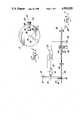
- FIG. 1is a schematic side view of a tube cutter mechanism for use with the tube feed arrangement of the invention
- FIG. 2is a schematic top view of the cutter of FIG. 1 and the tube feed and control mechanism according to the invention.
- FIG. 3is a partly broken away isometric view of the cutter mechanism of FIG. 1.
- the tube feeding method and apparatus to be describedare especially designed for facilitating tube cutting at a stationary station, however they also apply to other tube processing which can be done quickly at a stationary location.
- the inventionrecognizes that the cutting mechanism has greater inertia than the tube so that it is preferable to accelerate the tube rather than the cutting mechanism.
- the tubeis accelerated laterally to bow the tube.
- the bowis described as a simple arcuate curve but may also be an S-shape or other curve.
- the cutter wheel 10comprises a rotatable support 12 driven by a motor 14 for rotation about an axis 16.
- a knife 18is pivotably mounted for rotation about an axis 20 and is rotatably driven by means to be described.
- the knife 18is elongate and has a blade 22 at one end and a counterweight 24 at the other end.
- the blade 22extends beyond the periphery of the support 12 when the knife is angularly disposed with the blade outward but the counterweight does not ever extend beyond the support.
- the tube 26 to be cutis shown in section in FIG. 1 and is a flat thin walled tube of metal such as aluminum which is readily cut by a single stroke of a rapidly moving blade.
- the bladeis a well known structure called a Vogal knife which has a central cusp 28 for piercing the top of the tube and a curved concave blade portion 30 on either side of the cusp 28 for slicing through the side walls of the tube.
- the knife 18is arranged to rotate about its axis 20 several times for each rotation of the support 12. An intermediate knife position is shown at 18'. The knife is in position to intersect the path of the tube 26 only once during each rotation of the support 12 and the successive knife rotations are idle, allowing time for the tube to advance to the next desired cut-off point.
- the tubepreferably originates from a tube mill, not shown, and advances at a constant preset speed.
- the tube 26is advanced by drive rollers 32, operated by a motor 34 and is guided toward the cutter station by idler rollers 36.
- the cutter stationcomprises the vicinity of the cutter wheel 10 and has two sets of die blocks 38 spaced on opposite sides of the path of the blade 22 for positioning and supporting the tube 26 during the cut.
- a pair of pinch rollers 40engage the tube midway between the drive rollers 32 and the idler rollers 36.
- the pinch rollers 40are mounted on a slide 42 or the like for movement in a direction transverse to the tube advance movement.
- the slide 42carries a cam follower 44 which is driven by a cam 46.
- the cam 46in turn is rotated by a servomotor 48 controlled by a control circuit 50.
- the control circuit 50also controls the motor 14 and has an input from a position encoder 52 on the motor 14 which reveals the cutter wheel position to the control circuit.
- the tube millcan be expected to produce tubing at a rate of 600 feet per minute. Assuming the tube is to be cut at 2 foot lengths, the wheel speed will be 300 rpm. For a distance of 10 inches between the two axes of rotation and a knife length of 6 inches from its axis to the cutting edge, the linear velocity component due to the wheel rotation will be 500 inches per second. If the knife rotates at 3000 rpm, that adds a velocity component of 1800 ips. If the tube height is 13/8 inch and the blade height is 2 inches, the knife will be in contact with the tube for 0.00143 seconds. During that time the tube advance would be 0.172 inch. For a separation of six feet between the rollers 32 and 36, a bowing displacement of about 2.5 inch is adequate to produce the increased path length.
- a planetary gear setis used to rotate the knife 18 about its own pivot axis 20 and to revolve the knife about the axis 16 of the support 12.
- the support 12is the planetary carrier for the gear set.
- a fixed housing 55has a first cylindrical portion 56 which encloses the cuter wheel 10 and a second cylindrical portion 57 of greater diameter than the first which has room for knife rotation and has ports 58 which permit the tube 26 to pass through the cutting station.
- a stationary internal ring gear 60is secured to the housing by a hollow hub 62.
- the carrier or support 12is hollow and contains all the gears of the planetary gear set.
- the carrierhas a generally cylindrical shape and has a hub aperture 61 which is rotatably mounted by bearings 64 on the outer surface of the hub 62.
- the carrierhas an axle 63 extending opposite the bearings 64 which is journaled within a tubular boss 65 in the housing 55.
- a shaft 66is journaled in the hollow hub 62 and is driven at its outer end by the motor 14 and carries a sun gear 68 at its inner end.
- a pair of intermediate gears 70are rotatably mounted on the carrier 12 by bearings 72 and each gear 70 is compound, having a large diameter gear portion 70a which meshes with the sun gear and a small diameter gear portion 70b which meshes with the internal ring gear.
- a pair of outer pinions 74 and 76also carried by bearings 78 on the carrier 12, mesh with the large diameter gear portion 70a. The pinion 76 is coupled by a shaft 78 to the knife 18 for supporting and rotating the knife.
- the motor 14drives the sun gear 68 which causes the intermediate gears 70 to turn within the fixed ring gear 60 to drive the carrier 12.
- the motor rotation directionis chosen to rotate the carrier 12 in the cutting direction at the cutting station.
- the pinion 76 and the knifeare driven in the same direction so that all the forces join to move the knife 18 in the cutting direction.
- the knife 18makes many rotations, perhaps 10 or 15, depending on the gear ratios selected. During one rotation the knife will be positioned by the carrier 12 to cut the tube 26 and during all the other rotations the knife will not be in position to touch the tube.
- the blade of the knife 18is restricted to movement within a fixed plane and the tube, which is temporarily halted, is cut in that plane.
- the throughput of such a feeding and cutting arrangementis on the order of 600 feet per minute whereas the older style guillotine cutter and shuttle mechanism limited the throughput to 400 feet per minute.
Landscapes
- Engineering & Computer Science (AREA)
- Mechanical Engineering (AREA)
- Life Sciences & Earth Sciences (AREA)
- Forests & Forestry (AREA)
- Shearing Machines (AREA)
Abstract
Description
This invention relates to a method and apparatus for processing continuously manufactured tubing and particularly to a method and apparatus for feeding a continuously advancing tube for processing at a stationary site.
In the manufacture of tubing, a continuous tube is emitted from a tube mill at a high speed and the tube is cut into desired lengths as needed for specified usage or for convenient storage or shipping. The conventional cutting method uses a guillotine type cutter which chops the tube in a downward motion and is then retracted by an upward motion. In order not to interfere with the continuous advance of the tube, the knife, carried on a shuttle, moves in the direction of tube advance during cutting and retracting. Then the shuttle must return the knife to a start position for the next cut. Thus the alternating motion in two directions, forward and back motion of the shuttle and knife as well as up and down motion of the knife, is inefficient from the standpoint of overcoming inertia when reversing the movements. The inertia is substantial due to the considerable mass of the cutting mechanism. In addition, the time required for such cutting procedure places a limit on the production rate of the tubing.
It has been proposed to use a rotary knife motion for such purposes wherein a knife is moved in an arc during the cut and is then stopped and restarted in time for the next cut. In this case, the inertia of the knife must be overcome twice for each cut. That proposal does not overcome the need to shuttle the knife mechanism back and forth to accommodate tube motion during the cut.
It is therefore an object of the invention to provide a method and apparatus for feeding a continuously supplied tube in a manner to briefly stop it at an operating station. It is another object to provide such a method and apparatus for feeding a continuously manufactured tube to a stationary station for an operation in a fixed plane.
The method of the invention is carried out in a process for the continuous manufacture of an elongated tube by the method of momentarily stopping the tube at an operation station comprising the steps of; guiding the elongated tube through a travel path prior to the operation station, periodically increasing the length of the travel path, controlling the rate of the path length increase to momentarily stop the advance of the tube to the operation station while feeding of the tube into the travel path continues, whereby for the duration of the stop a portion of the tube at the operation station is essentially stationary to facilitate an operation thereon.
The invention is also carried out by apparatus for momentarily stopping a portion of a continuously fed tube in an operation station for performing an operation thereon comprising; an operation station, driving rolls for continuously advancing a tube in the direction of the operation station, idler rolls between the driving rolls and the operation station, means for bowing the tube including a guide between the idler rolls and the driving rolls for moving the tube laterally, and control means for moving the guide at a rate with respect to the tube advance rate sufficient to momentarily stop the tube advance at the idler rolls while the tube is continually advanced at the driving rolls.
The above and other advantages of the invention will become more apparent from the following description taken in conjunction with the accompanying drawings wherein like references refer to like parts and wherein:
FIG. 1 is a schematic side view of a tube cutter mechanism for use with the tube feed arrangement of the invention,
FIG. 2 is a schematic top view of the cutter of FIG. 1 and the tube feed and control mechanism according to the invention, and
FIG. 3 is a partly broken away isometric view of the cutter mechanism of FIG. 1.
The tube feeding method and apparatus to be described are especially designed for facilitating tube cutting at a stationary station, however they also apply to other tube processing which can be done quickly at a stationary location. The invention recognizes that the cutting mechanism has greater inertia than the tube so that it is preferable to accelerate the tube rather than the cutting mechanism. The tube is accelerated laterally to bow the tube. The bow is described as a simple arcuate curve but may also be an S-shape or other curve.
Referring to the drawings, thecutter wheel 10 comprises arotatable support 12 driven by amotor 14 for rotation about anaxis 16. Aknife 18 is pivotably mounted for rotation about anaxis 20 and is rotatably driven by means to be described. Theknife 18 is elongate and has ablade 22 at one end and a counterweight 24 at the other end. Theblade 22 extends beyond the periphery of thesupport 12 when the knife is angularly disposed with the blade outward but the counterweight does not ever extend beyond the support. Thetube 26 to be cut is shown in section in FIG. 1 and is a flat thin walled tube of metal such as aluminum which is readily cut by a single stroke of a rapidly moving blade. Preferably the blade is a well known structure called a Vogal knife which has acentral cusp 28 for piercing the top of the tube and a curvedconcave blade portion 30 on either side of thecusp 28 for slicing through the side walls of the tube. Theknife 18 is arranged to rotate about itsaxis 20 several times for each rotation of thesupport 12. An intermediate knife position is shown at 18'. The knife is in position to intersect the path of thetube 26 only once during each rotation of thesupport 12 and the successive knife rotations are idle, allowing time for the tube to advance to the next desired cut-off point.
The tube preferably originates from a tube mill, not shown, and advances at a constant preset speed. As shown in FIG. 2, thetube 26 is advanced bydrive rollers 32, operated by a motor 34 and is guided toward the cutter station byidler rollers 36. The cutter station comprises the vicinity of thecutter wheel 10 and has two sets ofdie blocks 38 spaced on opposite sides of the path of theblade 22 for positioning and supporting thetube 26 during the cut. For the purpose of momentarily stopping the tube advance at the idler rollers and at the cutting station, a pair ofpinch rollers 40 engage the tube midway between thedrive rollers 32 and theidler rollers 36. Thepinch rollers 40 are mounted on aslide 42 or the like for movement in a direction transverse to the tube advance movement. Theslide 42 carries a cam follower 44 which is driven by a cam 46. The cam 46, in turn is rotated by a servomotor 48 controlled by acontrol circuit 50. Thecontrol circuit 50 also controls themotor 14 and has an input from aposition encoder 52 on themotor 14 which reveals the cutter wheel position to the control circuit.
While the constant feed of the tube prevents stopping the tube altogether, transients can be introduced to the path of the tube to cause a momentary halt or hesitation of the tube at theidler rollers 36 without any disturbance to the constant feed at thedrive rollers 32. By increasing the effective path length between the drive rollers and the idler rollers at the same rate as the tube feed, the tube advance at theidler rollers 36 is stopped for as long as the increase of path length can be sustained. Then if the path length is decreased to return the tube to the original path, the tube speed at the idler rollers will temporarily be higher than the normal speed. The cam, driven by the servomotor 48, is under control of thecircuit 50 to rotate when the cutting action is about to take place thereby causing thepinch rollers 40 to bow thetube 26. The servomotor speed and the cam shape are calculated to effect the rate of displacement necessary to offset the advance during the increase of the path length so that the tube will be stationary at the cutting station for a brief time.
Typically the tube mill can be expected to produce tubing at a rate of 600 feet per minute. Assuming the tube is to be cut at 2 foot lengths, the wheel speed will be 300 rpm. For a distance of 10 inches between the two axes of rotation and a knife length of 6 inches from its axis to the cutting edge, the linear velocity component due to the wheel rotation will be 500 inches per second. If the knife rotates at 3000 rpm, that adds a velocity component of 1800 ips. If the tube height is 13/8 inch and the blade height is 2 inches, the knife will be in contact with the tube for 0.00143 seconds. During that time the tube advance would be 0.172 inch. For a separation of six feet between therollers
The details of the cutting wheel are shown in FIG. 3. A planetary gear set is used to rotate theknife 18 about itsown pivot axis 20 and to revolve the knife about theaxis 16 of thesupport 12. Thesupport 12 is the planetary carrier for the gear set. A fixed housing 55 has a firstcylindrical portion 56 which encloses thecuter wheel 10 and a second cylindrical portion 57 of greater diameter than the first which has room for knife rotation and hasports 58 which permit thetube 26 to pass through the cutting station. A stationaryinternal ring gear 60 is secured to the housing by a hollow hub 62. The carrier orsupport 12 is hollow and contains all the gears of the planetary gear set. The carrier has a generally cylindrical shape and has a hub aperture 61 which is rotatably mounted by bearings 64 on the outer surface of the hub 62. For additional support, the carrier has an axle 63 extending opposite the bearings 64 which is journaled within atubular boss 65 in the housing 55. A shaft 66 is journaled in the hollow hub 62 and is driven at its outer end by themotor 14 and carries a sun gear 68 at its inner end. A pair ofintermediate gears 70 are rotatably mounted on thecarrier 12 bybearings 72 and eachgear 70 is compound, having a large diameter gear portion 70a which meshes with the sun gear and a smalldiameter gear portion 70b which meshes with the internal ring gear. A pair of outer pinions 74 and 76, also carried by bearings 78 on thecarrier 12, mesh with the large diameter gear portion 70a. The pinion 76 is coupled by a shaft 78 to theknife 18 for supporting and rotating the knife.
In operation, themotor 14 drives the sun gear 68 which causes theintermediate gears 70 to turn within the fixedring gear 60 to drive thecarrier 12. The motor rotation direction is chosen to rotate thecarrier 12 in the cutting direction at the cutting station. The pinion 76 and the knife are driven in the same direction so that all the forces join to move theknife 18 in the cutting direction. As the carrier makes a single revolution, theknife 18 makes many rotations, perhaps 10 or 15, depending on the gear ratios selected. During one rotation the knife will be positioned by thecarrier 12 to cut thetube 26 and during all the other rotations the knife will not be in position to touch the tube. Since the housing is stationary and no part of thecutter wheel 10 moves in the direction of the tube motion, the blade of theknife 18 is restricted to movement within a fixed plane and the tube, which is temporarily halted, is cut in that plane. The throughput of such a feeding and cutting arrangement is on the order of 600 feet per minute whereas the older style guillotine cutter and shuttle mechanism limited the throughput to 400 feet per minute.
Claims (6)
1. In a process for the continuous manufacture of straight tubes of predetermined precise length from straight resilient tube stock, the method of momentarily stopping the tube stock at a cutting station comprising the steps of:
guiding the tube stock through a normally straight travel path to the cutting station,
periodically momentarily increasing a predetermined length of the travel path so as to stretch a portion of the tube stock in advance of the cutting station,
controlling the rate of the path length increase and thereby the amount of tube stock stretch to momentarily stop the advance of the tube stock at the cutting station while feeding of the tube stock along the travel path continues, whereby only for the duration of the momentary stop is the travel path increased and resultantly a portion of the tube stock at the cutting station measured from the leading end and encompassing the prescribed length is essentially stationary to facilitate a precise cutting operation thereon.
2. In a process for the continuous manufacture of straight tubes of predetermined precise length from straight resilient tube stock, the method of momentarily stopping the tube stock at a cutting station comprising the steps of:
guiding the tube stock in a normally straight travel path between an entry point and an exit point in advance of the cutting station,
elasticly deflecting the tube stock from its normally straight travel path between the entry and exit points to momentarily increase its path length therebetween while leaving that portion of the tube stock beyond the exit point free to travel a straight path to the cutting station;
controlling the tube stock deflection to momentarily stop the advance of the leading tube portion past the exit point while feeding of the tube stock at the entry point continues, whereby only for the duration of the momentary stop is the tube stock deflected and resultantly that portion of the tube stock beyond the exit point is essentially stationary to facilitate a precise cutting operation thereon.
3. In a process for the continuous manufacture of straight tubes of predetermined precise length from straight resilient tube stock, the method of cutting the tubes from straight tube stock at a stationary cutting station comprising the steps of:
guiding the tube stock in a normally straight path between an entry point and an exit point and then through the cutting station,
periodically elasticly deforming the tube stock by flexing the tube stock at a location intermediate the entry and exit points while leaving that portion of the tube stock beyond the exit point free to travel the straight path to the cutting station,
controlling the lateral movement to momentarily stop the advance of the tube stock past the exit point while feeding of the tube stock at the entry point continues, whereby only for the duration of the momentary stop is the tube stock bowed and resultantly a portion of the tube stock at the cutting station is essentially stationary, and
cutting the tube stock during the time that the tube stock is momentarily stationary in the cutting station.
4. In a process for the continuous manufacture of straight flat walled tubes of predetermined precise length, the method of cutting the tubes from straight flat walled resilient tube stock at a stationary cutting station comprising the steps of:
guiding the flat walled tube stock along a normally straight path between an entry point and an exit point and then through the cutting station,
continuously rotating a tube cutting knife about an axis spaced from and parallel to the tube stock and periodically moving the knife through the path of the tube stock for cutting the tube stock,
periodically elasticly bowing the tube stock by laterally moving the tube stock at a location intermediate the entry and exit points while leaving that portion of the tube stock beyond the exit point free to travel the straight path to the cutting station,
controlling the lateral movement in synchronism with the knife movement to momentarily stop the advance of the tube stock past the exit point while feeding of the tube stock at the entry point continues, whereby that portion of the tube stock at the cutting station is essentially momentarily stationary when the knife cuts the tube stock.
5. Apparatus for momentarily stopping a portion of a continuously fed piece of straight resilient tube stock in a cutting station for performing a precise cutting operation thereon comprising;
a cutting station,
driving rolls for continuously advancing a piece of straight tube stock in the direction of the cutting station, the driving rolls comprising two rollers contacting opposite sides of the tube stock,
drive means for driving one of the driving rollers,
idler rolls between the driving rolls and the cutting station, the idler rolls comprising two rollers contacting opposite sides of the tube stock,
means for elasticly bowing the tube stock including a guide between the idler rolls and the driving rolls for elasticly moving the tube stock laterally while leaving that portion of the tube stock beyond the idler rollers free to travel in a straight path to the cutting station, and
control means for moving the guide at a rate with respect to the tube stock advance rate sufficient to momentarily stop the tube stock advance past the idler rolls and thereby at the cutting station for precise cutting while the tube stock is continually advanced at the driving rolls.
6. Apparatus for cutting a continuously fed piece of straight resilient tube stock at a stationary cutting station comprising;
driving rolls for continuously advancing a piece of straight tube stock directly toward the cutting station,
idler rolls between the driving rolls and the cutting station,
a cutter at the cutter station for periodically cutting the tube stock,
means for stopping the tube stock advance at the cutting station during the cutting including guide means for elasticly bowing the tube stock between the idler rolls and the driving rolls for moving the tube stock laterally, and control means for moving the guide means synchronously with the cutter period at a rate with respect to the tube stock advance rate sufficient to momentarily stop the tube advance past the idler rolls and thereby at the cutting station for precise cutting while the tube stock is continually advanced at the driving rolls.
Priority Applications (1)
| Application Number | Priority Date | Filing Date | Title |
|---|---|---|---|
| US07/261,306US4919025A (en) | 1988-10-24 | 1988-10-24 | Method and apparatus for processing continuously manufactured tubing |
Applications Claiming Priority (1)
| Application Number | Priority Date | Filing Date | Title |
|---|---|---|---|
| US07/261,306US4919025A (en) | 1988-10-24 | 1988-10-24 | Method and apparatus for processing continuously manufactured tubing |
Publications (1)
| Publication Number | Publication Date |
|---|---|
| US4919025Atrue US4919025A (en) | 1990-04-24 |
Family
ID=22992723
Family Applications (1)
| Application Number | Title | Priority Date | Filing Date |
|---|---|---|---|
| US07/261,306Expired - Fee RelatedUS4919025A (en) | 1988-10-24 | 1988-10-24 | Method and apparatus for processing continuously manufactured tubing |
Country Status (1)
| Country | Link |
|---|---|
| US (1) | US4919025A (en) |
Cited By (10)
| Publication number | Priority date | Publication date | Assignee | Title |
|---|---|---|---|---|
| US5063801A (en)* | 1989-01-23 | 1991-11-12 | Wallis Bernard J | Cut-off machine and method for tubing |
| US5407382A (en)* | 1994-05-26 | 1995-04-18 | Teepak, Inc. | Method and apparatus for severing tubular material around a mandrel |
| US5664472A (en)* | 1995-06-29 | 1997-09-09 | Mitsubishi Denki Kabushiki Kaisha | Cutter apparatus for coil conductor |
| US5826479A (en)* | 1993-08-03 | 1998-10-27 | Nippondenso Co., Ltd. | Cutting device |
| US5927124A (en)* | 1996-03-05 | 1999-07-27 | Adaptive Motion Control Systems, Inc. | Apparatus for bending and cutting tubing, and method of using same |
| US5931075A (en)* | 1994-08-31 | 1999-08-03 | Nippondenso Co., Ltd. | Method and apparatus for cutting flat tube |
| US6260395B1 (en) | 1996-03-05 | 2001-07-17 | Adaptive Motion Control Systems, Inc. | Vertically oriented apparatus for bending tubing, and method of using same |
| ITMI20092269A1 (en)* | 2009-12-22 | 2011-06-23 | Piccoli S R L | AUTOMATIC CUTTER OF FLEXIBLE TUBES WITH LINEAR BLADE MOUNTED ON A PIVOTING AND ROTARY ARM ALTERNATIVELY OF A FIXED ANGLE |
| US20150158099A1 (en)* | 2013-12-06 | 2015-06-11 | Fives Oto S.P.A. | Cutting-off machine |
| US20170339976A1 (en)* | 2014-12-02 | 2017-11-30 | Nestec S.A. | Apparatus and method for cutting or embossing coatings |
Citations (6)
| Publication number | Priority date | Publication date | Assignee | Title |
|---|---|---|---|---|
| US3053129A (en)* | 1958-10-13 | 1962-09-11 | Commercial Envelope Mfg Co Inc | High speed means for feeding a strip with constant speed input but with intermittent motion at the work location |
| US3085457A (en)* | 1960-03-11 | 1963-04-16 | Champlain Company Inc | High speed web stopping mechanism |
| US3102673A (en)* | 1958-06-09 | 1963-09-03 | Commercial Envelope Mfg Co Inc | Strip feeding means |
| US3655856A (en)* | 1970-03-12 | 1972-04-11 | Phillips Petroleum Co | Method of intermittently severing continuously formed extrudate |
| US3882744A (en)* | 1973-08-24 | 1975-05-13 | Xerox Corp | Electrostatographic web feeding apparatus |
| US4060187A (en)* | 1975-11-26 | 1977-11-29 | J. Bobst & Fils, S.A. | Process and apparatus for permanently controlling the movement of web of material continuously delivered to a machine processing the web |
- 1988
- 1988-10-24USUS07/261,306patent/US4919025A/ennot_activeExpired - Fee Related
Patent Citations (6)
| Publication number | Priority date | Publication date | Assignee | Title |
|---|---|---|---|---|
| US3102673A (en)* | 1958-06-09 | 1963-09-03 | Commercial Envelope Mfg Co Inc | Strip feeding means |
| US3053129A (en)* | 1958-10-13 | 1962-09-11 | Commercial Envelope Mfg Co Inc | High speed means for feeding a strip with constant speed input but with intermittent motion at the work location |
| US3085457A (en)* | 1960-03-11 | 1963-04-16 | Champlain Company Inc | High speed web stopping mechanism |
| US3655856A (en)* | 1970-03-12 | 1972-04-11 | Phillips Petroleum Co | Method of intermittently severing continuously formed extrudate |
| US3882744A (en)* | 1973-08-24 | 1975-05-13 | Xerox Corp | Electrostatographic web feeding apparatus |
| US4060187A (en)* | 1975-11-26 | 1977-11-29 | J. Bobst & Fils, S.A. | Process and apparatus for permanently controlling the movement of web of material continuously delivered to a machine processing the web |
Cited By (13)
| Publication number | Priority date | Publication date | Assignee | Title |
|---|---|---|---|---|
| US5063801A (en)* | 1989-01-23 | 1991-11-12 | Wallis Bernard J | Cut-off machine and method for tubing |
| US5826479A (en)* | 1993-08-03 | 1998-10-27 | Nippondenso Co., Ltd. | Cutting device |
| US5407382A (en)* | 1994-05-26 | 1995-04-18 | Teepak, Inc. | Method and apparatus for severing tubular material around a mandrel |
| US5931075A (en)* | 1994-08-31 | 1999-08-03 | Nippondenso Co., Ltd. | Method and apparatus for cutting flat tube |
| US5826471A (en)* | 1995-06-29 | 1998-10-27 | Mitsubishi Denki Kabushika Kaisha | Cutting method for coil conductor |
| US5664472A (en)* | 1995-06-29 | 1997-09-09 | Mitsubishi Denki Kabushiki Kaisha | Cutter apparatus for coil conductor |
| US5927124A (en)* | 1996-03-05 | 1999-07-27 | Adaptive Motion Control Systems, Inc. | Apparatus for bending and cutting tubing, and method of using same |
| US6260395B1 (en) | 1996-03-05 | 2001-07-17 | Adaptive Motion Control Systems, Inc. | Vertically oriented apparatus for bending tubing, and method of using same |
| ITMI20092269A1 (en)* | 2009-12-22 | 2011-06-23 | Piccoli S R L | AUTOMATIC CUTTER OF FLEXIBLE TUBES WITH LINEAR BLADE MOUNTED ON A PIVOTING AND ROTARY ARM ALTERNATIVELY OF A FIXED ANGLE |
| US20150158099A1 (en)* | 2013-12-06 | 2015-06-11 | Fives Oto S.P.A. | Cutting-off machine |
| US9434012B2 (en)* | 2013-12-06 | 2016-09-06 | Fives Oto S.P.A. | Cutting-off machine |
| US20170339976A1 (en)* | 2014-12-02 | 2017-11-30 | Nestec S.A. | Apparatus and method for cutting or embossing coatings |
| US10709150B2 (en)* | 2014-12-02 | 2020-07-14 | Societe Des Produits Nestle S.A. | Apparatus and method for cutting or embossing coatings |
Similar Documents
| Publication | Publication Date | Title |
|---|---|---|
| US4919025A (en) | Method and apparatus for processing continuously manufactured tubing | |
| RU96108930A (en) | MACHINE FOR PRODUCING PIPES FROM CARDBOARD OR SIMILAR MATERIAL, WITH THE MEANS OF CUTTING PIPES FOR CUTS OF THE SET LENGTH | |
| US4378966A (en) | Apparatus for controlling a pipe-cutting device | |
| US6705355B1 (en) | Wire straightening and cut-off machine and process | |
| US5992282A (en) | Device for cutting continuous cigarette rods | |
| US5311802A (en) | Tube cut off machine | |
| US4555924A (en) | Automatic machine for curving, in a spatial configuration, thin and rectilinear metal elements, more especially metal wires | |
| KR100260050B1 (en) | Spirally wound metal pipe cutting machine | |
| US4941378A (en) | Method and apparatus for rapid repetitive cutting | |
| EP0440327B1 (en) | Cut-off machine and method for tubing | |
| US4739683A (en) | Apparatus for cutting material sheet into trapezoidal pieces | |
| JP2954981B2 (en) | Method and apparatus for cutting tubes into individual tube pieces | |
| US4939967A (en) | Cut-off machine | |
| JP2571216B2 (en) | Spring winding machine | |
| US3983772A (en) | Cutting machine | |
| US4191078A (en) | Wire cutting flying shear | |
| JPH0478407B2 (en) | ||
| JPH0688232B2 (en) | Equipment for cutting raw material strands into unit pieces | |
| US3254549A (en) | Tube cutting means for tube winding machines | |
| EP0723489B1 (en) | Rotary shearing machine with opposed blades that rotates as desired around geometrical axes substantially orthogonal to the cutting plane | |
| JPH11151611A (en) | Cutting device of corrugated fin | |
| JP3838755B2 (en) | Traveling pipe cutting device | |
| US3216300A (en) | Work driven flying cut-off machine | |
| KR900000437Y1 (en) | Cutting device of wire | |
| GB1008241A (en) | Improvements in machines for cutting lengths of strip material |
Legal Events
| Date | Code | Title | Description |
|---|---|---|---|
| AS | Assignment | Owner name:GENERAL MOTORS CORPORATION, DETROIT, MICHIGAN, A C Free format text:ASSIGNMENT OF ASSIGNORS INTEREST.;ASSIGNOR:SNYDER, GEORGE K.;REEL/FRAME:004962/0865 Effective date:19881003 Owner name:GENERAL MOTORS CORPORATION, A CORP. OF DE, MICHIGA Free format text:ASSIGNMENT OF ASSIGNORS INTEREST;ASSIGNOR:SNYDER, GEORGE K.;REEL/FRAME:004962/0865 Effective date:19881003 | |
| FEPP | Fee payment procedure | Free format text:PAYOR NUMBER ASSIGNED (ORIGINAL EVENT CODE: ASPN); ENTITY STATUS OF PATENT OWNER: LARGE ENTITY | |
| FPAY | Fee payment | Year of fee payment:4 | |
| SULP | Surcharge for late payment | ||
| FEPP | Fee payment procedure | Free format text:PAYER NUMBER DE-ASSIGNED (ORIGINAL EVENT CODE: RMPN); ENTITY STATUS OF PATENT OWNER: LARGE ENTITY | |
| FPAY | Fee payment | Year of fee payment:8 | |
| LAPS | Lapse for failure to pay maintenance fees | ||
| STCH | Information on status: patent discontinuation | Free format text:PATENT EXPIRED DUE TO NONPAYMENT OF MAINTENANCE FEES UNDER 37 CFR 1.362 | |
| FP | Lapsed due to failure to pay maintenance fee | Effective date:20020424 |