US4918690A - Network and intelligent cell for providing sensing, bidirectional communications and control - Google Patents
Network and intelligent cell for providing sensing, bidirectional communications and controlDownload PDFInfo
- Publication number
- US4918690A US4918690AUS07/119,330US11933087AUS4918690AUS 4918690 AUS4918690 AUS 4918690AUS 11933087 AUS11933087 AUS 11933087AUS 4918690 AUS4918690 AUS 4918690A
- Authority
- US
- United States
- Prior art keywords
- cell
- cells
- group
- bits
- network
- Prior art date
- Legal status (The legal status is an assumption and is not a legal conclusion. Google has not performed a legal analysis and makes no representation as to the accuracy of the status listed.)
- Expired - Lifetime
Links
- 230000007175bidirectional communicationEffects0.000titledescription2
- 230000006870functionEffects0.000claimsabstractdescription79
- 230000006854communicationEffects0.000claimsabstractdescription58
- 238000004891communicationMethods0.000claimsabstractdescription58
- 230000004044responseEffects0.000claimsdescription10
- 230000015572biosynthetic processEffects0.000claimsdescription7
- 230000008878couplingEffects0.000claimsdescription6
- 238000010168coupling processMethods0.000claimsdescription6
- 238000005859coupling reactionMethods0.000claimsdescription6
- 239000004065semiconductorSubstances0.000claimsdescription6
- 210000004027cellAnatomy0.000description517
- 238000000034methodMethods0.000description61
- 239000000523sampleSubstances0.000description35
- 230000007704transitionEffects0.000description29
- 238000010586diagramMethods0.000description25
- 230000005540biological transmissionEffects0.000description18
- 230000008569processEffects0.000description17
- 238000004364calculation methodMethods0.000description11
- 238000006243chemical reactionMethods0.000description11
- 230000001276controlling effectEffects0.000description11
- 238000001514detection methodMethods0.000description10
- 230000008030eliminationEffects0.000description9
- 238000003379elimination reactionMethods0.000description9
- 238000004519manufacturing processMethods0.000description8
- 238000012545processingMethods0.000description8
- 230000009471actionEffects0.000description7
- 230000007246mechanismEffects0.000description7
- 238000012360testing methodMethods0.000description6
- 238000009434installationMethods0.000description5
- 230000000873masking effectEffects0.000description5
- 230000001360synchronised effectEffects0.000description5
- 239000003990capacitorSubstances0.000description4
- 230000008859changeEffects0.000description4
- 230000000295complement effectEffects0.000description4
- 230000002452interceptive effectEffects0.000description4
- 235000008694Humulus lupulusNutrition0.000description3
- 230000002457bidirectional effectEffects0.000description3
- 230000000694effectsEffects0.000description3
- 230000004936stimulating effectEffects0.000description3
- 241000131971BradyrhizobiaceaeSpecies0.000description2
- 230000003213activating effectEffects0.000description2
- 238000013473artificial intelligenceMethods0.000description2
- 238000010276constructionMethods0.000description2
- 230000001934delayEffects0.000description2
- 230000003111delayed effectEffects0.000description2
- 238000005516engineering processMethods0.000description2
- 230000006872improvementEffects0.000description2
- 230000010363phase shiftEffects0.000description2
- 239000000779smokeSubstances0.000description2
- 230000000638stimulationEffects0.000description2
- 238000003860storageMethods0.000description2
- 101001022148Homo sapiens FurinProteins0.000description1
- 101000701936Homo sapiens Signal peptidase complex subunit 1Proteins0.000description1
- OFFWOVJBSQMVPI-RMLGOCCBSA-NKaletraChemical compoundN1([C@@H](C(C)C)C(=O)N[C@H](C[C@H](O)[C@H](CC=2C=CC=CC=2)NC(=O)COC=2C(=CC=CC=2C)C)CC=2C=CC=CC=2)CCCNC1=O.N([C@@H](C(C)C)C(=O)N[C@H](C[C@H](O)[C@H](CC=1C=CC=CC=1)NC(=O)OCC=1SC=NC=1)CC=1C=CC=CC=1)C(=O)N(C)CC1=CSC(C(C)C)=N1OFFWOVJBSQMVPI-RMLGOCCBSA-N0.000description1
- 241001465754MetazoaSpecies0.000description1
- 102100026827Protein associated with UVRAG as autophagy enhancerHuman genes0.000description1
- 101710102978Protein associated with UVRAG as autophagy enhancerProteins0.000description1
- 102100030313Signal peptidase complex subunit 1Human genes0.000description1
- XUIMIQQOPSSXEZ-UHFFFAOYSA-NSiliconChemical compound[Si]XUIMIQQOPSSXEZ-UHFFFAOYSA-N0.000description1
- 241000607479Yersinia pestisSpecies0.000description1
- 230000002238attenuated effectEffects0.000description1
- 230000008901benefitEffects0.000description1
- 230000003139buffering effectEffects0.000description1
- 230000008568cell cell communicationEffects0.000description1
- 230000003915cell functionEffects0.000description1
- 239000013078crystalSubstances0.000description1
- 125000004122cyclic groupChemical group0.000description1
- 229940079593drugDrugs0.000description1
- 239000003814drugSubstances0.000description1
- 239000000284extractSubstances0.000description1
- 238000007667floatingMethods0.000description1
- 239000007943implantSubstances0.000description1
- 230000010365information processingEffects0.000description1
- 230000000977initiatory effectEffects0.000description1
- 230000002262irrigationEffects0.000description1
- 238000003973irrigationMethods0.000description1
- 238000005304joiningMethods0.000description1
- 244000144972livestockSpecies0.000description1
- 238000012423maintenanceMethods0.000description1
- 238000012544monitoring processMethods0.000description1
- 210000002569neuronAnatomy0.000description1
- 235000001968nicotinic acidNutrition0.000description1
- 239000003921oilSubstances0.000description1
- 230000003287optical effectEffects0.000description1
- 230000008520organizationEffects0.000description1
- 230000002093peripheral effectEffects0.000description1
- 230000001902propagating effectEffects0.000description1
- 230000001105regulatory effectEffects0.000description1
- 229920006395saturated elastomerPolymers0.000description1
- 229910052710siliconInorganic materials0.000description1
- 239000010703siliconSubstances0.000description1
- 230000007480spreadingEffects0.000description1
- 238000003892spreadingMethods0.000description1
- 230000003068static effectEffects0.000description1
- 239000000758substrateSubstances0.000description1
- 238000004804windingMethods0.000description1
Images


Classifications
- H—ELECTRICITY
- H04—ELECTRIC COMMUNICATION TECHNIQUE
- H04Q—SELECTING
- H04Q3/00—Selecting arrangements
- G—PHYSICS
- G05—CONTROLLING; REGULATING
- G05B—CONTROL OR REGULATING SYSTEMS IN GENERAL; FUNCTIONAL ELEMENTS OF SUCH SYSTEMS; MONITORING OR TESTING ARRANGEMENTS FOR SUCH SYSTEMS OR ELEMENTS
- G05B19/00—Programme-control systems
- G05B19/02—Programme-control systems electric
- G05B19/04—Programme control other than numerical control, i.e. in sequence controllers or logic controllers
- G05B19/042—Programme control other than numerical control, i.e. in sequence controllers or logic controllers using digital processors
- G05B19/0421—Multiprocessor system
- G—PHYSICS
- G08—SIGNALLING
- G08C—TRANSMISSION SYSTEMS FOR MEASURED VALUES, CONTROL OR SIMILAR SIGNALS
- G08C15/00—Arrangements characterised by the use of multiplexing for the transmission of a plurality of signals over a common path
- H—ELECTRICITY
- H04—ELECTRIC COMMUNICATION TECHNIQUE
- H04L—TRANSMISSION OF DIGITAL INFORMATION, e.g. TELEGRAPHIC COMMUNICATION
- H04L12/00—Data switching networks
- H04L12/28—Data switching networks characterised by path configuration, e.g. LAN [Local Area Networks] or WAN [Wide Area Networks]
- H04L12/2803—Home automation networks
- H04L12/2816—Controlling appliance services of a home automation network by calling their functionalities
- H04L12/282—Controlling appliance services of a home automation network by calling their functionalities based on user interaction within the home
- H—ELECTRICITY
- H04—ELECTRIC COMMUNICATION TECHNIQUE
- H04L—TRANSMISSION OF DIGITAL INFORMATION, e.g. TELEGRAPHIC COMMUNICATION
- H04L12/00—Data switching networks
- H04L12/28—Data switching networks characterised by path configuration, e.g. LAN [Local Area Networks] or WAN [Wide Area Networks]
- H04L12/2803—Home automation networks
- H04L12/2838—Distribution of signals within a home automation network, e.g. involving splitting/multiplexing signals to/from different paths
- H—ELECTRICITY
- H04—ELECTRIC COMMUNICATION TECHNIQUE
- H04W—WIRELESS COMMUNICATION NETWORKS
- H04W12/00—Security arrangements; Authentication; Protecting privacy or anonymity
- H04W12/08—Access security
- H—ELECTRICITY
- H05—ELECTRIC TECHNIQUES NOT OTHERWISE PROVIDED FOR
- H05B—ELECTRIC HEATING; ELECTRIC LIGHT SOURCES NOT OTHERWISE PROVIDED FOR; CIRCUIT ARRANGEMENTS FOR ELECTRIC LIGHT SOURCES, IN GENERAL
- H05B47/00—Circuit arrangements for operating light sources in general, i.e. where the type of light source is not relevant
- H05B47/10—Controlling the light source
- H05B47/155—Coordinated control of two or more light sources
- G—PHYSICS
- G05—CONTROLLING; REGULATING
- G05B—CONTROL OR REGULATING SYSTEMS IN GENERAL; FUNCTIONAL ELEMENTS OF SUCH SYSTEMS; MONITORING OR TESTING ARRANGEMENTS FOR SUCH SYSTEMS OR ELEMENTS
- G05B2219/00—Program-control systems
- G05B2219/20—Pc systems
- G05B2219/21—Pc I-O input output
- G05B2219/21042—Address a group, a zone
- G—PHYSICS
- G05—CONTROLLING; REGULATING
- G05B—CONTROL OR REGULATING SYSTEMS IN GENERAL; FUNCTIONAL ELEMENTS OF SUCH SYSTEMS; MONITORING OR TESTING ARRANGEMENTS FOR SUCH SYSTEMS OR ELEMENTS
- G05B2219/00—Program-control systems
- G05B2219/20—Pc systems
- G05B2219/21—Pc I-O input output
- G05B2219/21053—Each unit, module has unique identification code, set during manufacturing, fMAC address
- G—PHYSICS
- G05—CONTROLLING; REGULATING
- G05B—CONTROL OR REGULATING SYSTEMS IN GENERAL; FUNCTIONAL ELEMENTS OF SUCH SYSTEMS; MONITORING OR TESTING ARRANGEMENTS FOR SUCH SYSTEMS OR ELEMENTS
- G05B2219/00—Program-control systems
- G05B2219/20—Pc systems
- G05B2219/25—Pc structure of the system
- G05B2219/25086—Assign functions to group of complete or partial cells, modules
- G—PHYSICS
- G05—CONTROLLING; REGULATING
- G05B—CONTROL OR REGULATING SYSTEMS IN GENERAL; FUNCTIONAL ELEMENTS OF SUCH SYSTEMS; MONITORING OR TESTING ARRANGEMENTS FOR SUCH SYSTEMS OR ELEMENTS
- G05B2219/00—Program-control systems
- G05B2219/20—Pc systems
- G05B2219/25—Pc structure of the system
- G05B2219/25162—Contention, if several transmitters avoid collision, by separate transmittor code
- G—PHYSICS
- G05—CONTROLLING; REGULATING
- G05B—CONTROL OR REGULATING SYSTEMS IN GENERAL; FUNCTIONAL ELEMENTS OF SUCH SYSTEMS; MONITORING OR TESTING ARRANGEMENTS FOR SUCH SYSTEMS OR ELEMENTS
- G05B2219/00—Program-control systems
- G05B2219/20—Pc systems
- G05B2219/25—Pc structure of the system
- G05B2219/25163—Transmit twice, redundant, same data on different channels, check each channel
- G—PHYSICS
- G05—CONTROLLING; REGULATING
- G05B—CONTROL OR REGULATING SYSTEMS IN GENERAL; FUNCTIONAL ELEMENTS OF SUCH SYSTEMS; MONITORING OR TESTING ARRANGEMENTS FOR SUCH SYSTEMS OR ELEMENTS
- G05B2219/00—Program-control systems
- G05B2219/20—Pc systems
- G05B2219/25—Pc structure of the system
- G05B2219/25178—Serial communication, data, also repeater
- G—PHYSICS
- G05—CONTROLLING; REGULATING
- G05B—CONTROL OR REGULATING SYSTEMS IN GENERAL; FUNCTIONAL ELEMENTS OF SUCH SYSTEMS; MONITORING OR TESTING ARRANGEMENTS FOR SUCH SYSTEMS OR ELEMENTS
- G05B2219/00—Program-control systems
- G05B2219/20—Pc systems
- G05B2219/25—Pc structure of the system
- G05B2219/25187—Transmission of signals, medium, ultrasonic, radio
- G—PHYSICS
- G05—CONTROLLING; REGULATING
- G05B—CONTROL OR REGULATING SYSTEMS IN GENERAL; FUNCTIONAL ELEMENTS OF SUCH SYSTEMS; MONITORING OR TESTING ARRANGEMENTS FOR SUCH SYSTEMS OR ELEMENTS
- G05B2219/00—Program-control systems
- G05B2219/20—Pc systems
- G05B2219/25—Pc structure of the system
- G05B2219/25192—Infrared
- G—PHYSICS
- G05—CONTROLLING; REGULATING
- G05B—CONTROL OR REGULATING SYSTEMS IN GENERAL; FUNCTIONAL ELEMENTS OF SUCH SYSTEMS; MONITORING OR TESTING ARRANGEMENTS FOR SUCH SYSTEMS OR ELEMENTS
- G05B2219/00—Program-control systems
- G05B2219/20—Pc systems
- G05B2219/25—Pc structure of the system
- G05B2219/25193—Coaxial cable
- G—PHYSICS
- G05—CONTROLLING; REGULATING
- G05B—CONTROL OR REGULATING SYSTEMS IN GENERAL; FUNCTIONAL ELEMENTS OF SUCH SYSTEMS; MONITORING OR TESTING ARRANGEMENTS FOR SUCH SYSTEMS OR ELEMENTS
- G05B2219/00—Program-control systems
- G05B2219/20—Pc systems
- G05B2219/25—Pc structure of the system
- G05B2219/25196—Radio link, transponder
- G—PHYSICS
- G05—CONTROLLING; REGULATING
- G05B—CONTROL OR REGULATING SYSTEMS IN GENERAL; FUNCTIONAL ELEMENTS OF SUCH SYSTEMS; MONITORING OR TESTING ARRANGEMENTS FOR SUCH SYSTEMS OR ELEMENTS
- G05B2219/00—Program-control systems
- G05B2219/20—Pc systems
- G05B2219/25—Pc structure of the system
- G05B2219/25197—Optical, glass fiber
- G—PHYSICS
- G05—CONTROLLING; REGULATING
- G05B—CONTROL OR REGULATING SYSTEMS IN GENERAL; FUNCTIONAL ELEMENTS OF SUCH SYSTEMS; MONITORING OR TESTING ARRANGEMENTS FOR SUCH SYSTEMS OR ELEMENTS
- G05B2219/00—Program-control systems
- G05B2219/20—Pc systems
- G05B2219/25—Pc structure of the system
- G05B2219/25219—Probe packet to determine best route for messages
- G—PHYSICS
- G05—CONTROLLING; REGULATING
- G05B—CONTROL OR REGULATING SYSTEMS IN GENERAL; FUNCTIONAL ELEMENTS OF SUCH SYSTEMS; MONITORING OR TESTING ARRANGEMENTS FOR SUCH SYSTEMS OR ELEMENTS
- G05B2219/00—Program-control systems
- G05B2219/20—Pc systems
- G05B2219/25—Pc structure of the system
- G05B2219/25234—Direct communication between two modules instead of normal network
- G—PHYSICS
- G05—CONTROLLING; REGULATING
- G05B—CONTROL OR REGULATING SYSTEMS IN GENERAL; FUNCTIONAL ELEMENTS OF SUCH SYSTEMS; MONITORING OR TESTING ARRANGEMENTS FOR SUCH SYSTEMS OR ELEMENTS
- G05B2219/00—Program-control systems
- G05B2219/20—Pc systems
- G05B2219/26—Pc applications
- G05B2219/2642—Domotique, domestic, home control, automation, smart house
- H—ELECTRICITY
- H04—ELECTRIC COMMUNICATION TECHNIQUE
- H04L—TRANSMISSION OF DIGITAL INFORMATION, e.g. TELEGRAPHIC COMMUNICATION
- H04L12/00—Data switching networks
- H04L12/28—Data switching networks characterised by path configuration, e.g. LAN [Local Area Networks] or WAN [Wide Area Networks]
- H04L12/2803—Home automation networks
- H04L12/2807—Exchanging configuration information on appliance services in a home automation network
- H04L12/2814—Exchanging control software or macros for controlling appliance services in a home automation network
- H—ELECTRICITY
- H04—ELECTRIC COMMUNICATION TECHNIQUE
- H04L—TRANSMISSION OF DIGITAL INFORMATION, e.g. TELEGRAPHIC COMMUNICATION
- H04L12/00—Data switching networks
- H04L12/28—Data switching networks characterised by path configuration, e.g. LAN [Local Area Networks] or WAN [Wide Area Networks]
- H04L12/2803—Home automation networks
- H04L12/2823—Reporting information sensed by appliance or service execution status of appliance services in a home automation network
- H—ELECTRICITY
- H04—ELECTRIC COMMUNICATION TECHNIQUE
- H04L—TRANSMISSION OF DIGITAL INFORMATION, e.g. TELEGRAPHIC COMMUNICATION
- H04L12/00—Data switching networks
- H04L12/28—Data switching networks characterised by path configuration, e.g. LAN [Local Area Networks] or WAN [Wide Area Networks]
- H04L12/2803—Home automation networks
- H04L2012/284—Home automation networks characterised by the type of medium used
- H04L2012/2841—Wireless
- H—ELECTRICITY
- H04—ELECTRIC COMMUNICATION TECHNIQUE
- H04L—TRANSMISSION OF DIGITAL INFORMATION, e.g. TELEGRAPHIC COMMUNICATION
- H04L12/00—Data switching networks
- H04L12/28—Data switching networks characterised by path configuration, e.g. LAN [Local Area Networks] or WAN [Wide Area Networks]
- H04L12/2803—Home automation networks
- H04L2012/284—Home automation networks characterised by the type of medium used
- H04L2012/2843—Mains power line
- H—ELECTRICITY
- H04—ELECTRIC COMMUNICATION TECHNIQUE
- H04L—TRANSMISSION OF DIGITAL INFORMATION, e.g. TELEGRAPHIC COMMUNICATION
- H04L12/00—Data switching networks
- H04L12/28—Data switching networks characterised by path configuration, e.g. LAN [Local Area Networks] or WAN [Wide Area Networks]
- H04L12/2803—Home automation networks
- H04L2012/2847—Home automation networks characterised by the type of home appliance used
- H04L2012/285—Generic home appliances, e.g. refrigerators
- H—ELECTRICITY
- H04—ELECTRIC COMMUNICATION TECHNIQUE
- H04L—TRANSMISSION OF DIGITAL INFORMATION, e.g. TELEGRAPHIC COMMUNICATION
- H04L63/00—Network architectures or network communication protocols for network security
- H04L63/10—Network architectures or network communication protocols for network security for controlling access to devices or network resources
- H04L63/104—Grouping of entities
- Y—GENERAL TAGGING OF NEW TECHNOLOGICAL DEVELOPMENTS; GENERAL TAGGING OF CROSS-SECTIONAL TECHNOLOGIES SPANNING OVER SEVERAL SECTIONS OF THE IPC; TECHNICAL SUBJECTS COVERED BY FORMER USPC CROSS-REFERENCE ART COLLECTIONS [XRACs] AND DIGESTS
- Y02—TECHNOLOGIES OR APPLICATIONS FOR MITIGATION OR ADAPTATION AGAINST CLIMATE CHANGE
- Y02B—CLIMATE CHANGE MITIGATION TECHNOLOGIES RELATED TO BUILDINGS, e.g. HOUSING, HOUSE APPLIANCES OR RELATED END-USER APPLICATIONS
- Y02B20/00—Energy efficient lighting technologies, e.g. halogen lamps or gas discharge lamps
- Y02B20/40—Control techniques providing energy savings, e.g. smart controller or presence detection
- Y—GENERAL TAGGING OF NEW TECHNOLOGICAL DEVELOPMENTS; GENERAL TAGGING OF CROSS-SECTIONAL TECHNOLOGIES SPANNING OVER SEVERAL SECTIONS OF THE IPC; TECHNICAL SUBJECTS COVERED BY FORMER USPC CROSS-REFERENCE ART COLLECTIONS [XRACs] AND DIGESTS
- Y02—TECHNOLOGIES OR APPLICATIONS FOR MITIGATION OR ADAPTATION AGAINST CLIMATE CHANGE
- Y02D—CLIMATE CHANGE MITIGATION TECHNOLOGIES IN INFORMATION AND COMMUNICATION TECHNOLOGIES [ICT], I.E. INFORMATION AND COMMUNICATION TECHNOLOGIES AIMING AT THE REDUCTION OF THEIR OWN ENERGY USE
- Y02D30/00—Reducing energy consumption in communication networks
- Y02D30/70—Reducing energy consumption in communication networks in wireless communication networks
- Y—GENERAL TAGGING OF NEW TECHNOLOGICAL DEVELOPMENTS; GENERAL TAGGING OF CROSS-SECTIONAL TECHNOLOGIES SPANNING OVER SEVERAL SECTIONS OF THE IPC; TECHNICAL SUBJECTS COVERED BY FORMER USPC CROSS-REFERENCE ART COLLECTIONS [XRACs] AND DIGESTS
- Y02—TECHNOLOGIES OR APPLICATIONS FOR MITIGATION OR ADAPTATION AGAINST CLIMATE CHANGE
- Y02P—CLIMATE CHANGE MITIGATION TECHNOLOGIES IN THE PRODUCTION OR PROCESSING OF GOODS
- Y02P80/00—Climate change mitigation technologies for sector-wide applications
- Y02P80/10—Efficient use of energy, e.g. using compressed air or pressurized fluid as energy carrier
Definitions
- the inventionrelates to the field of networks with distributed intelligence, configuration and control and intelligent cells used in networks, primarily where the networks are used for sensing, communicating and controlling.
- the present inventionis directed towards providing a system having a relatively large amount of intelligence and computational power but at a low cost.
- One commercially available system "X-10"provides control, by way of example, between a light switch and a light.
- a code patternis transmitted over the power lines to a receiver at the light.
- the code patternis transmitted twice, once in its true form and once in its complementary form.
- the codeis received by the receiver, it is interpreted, and thereby used to control the light.
- Mechanical addressing meansare employed to allow the transmitter at the switch to communicate with the specific desired receiver at the light.
- the present inventionprovides substantially more capability and flexibility than current systems.
- a network for providing sensing, communications and controlis described.
- a plurality of intelligent cellseach of which comprises an integrated circuit having a processor and input/output section are coupled to the network.
- Each of the programmable cellsreceives, when manufactured, a unique identification number (48 bits) which remains permanently within the cell.
- the cellscan be coupled to different media such as power lines, twisted pair, radio frequency, infrared ultrasonic, optical coaxial, etc., to form a network.
- Networksare distinguished from one another by system identification numbers (IDs). Groups of cells within each network are formed to perform particular functions and are identified by group IDs. Communications occur within the network through use of the system, group and cell IDs. Some cells (announcers) are assigned the task of sensing, for example, the condition of a switch, and others (listeners) the task of controlling, such as controlling a light. Cells can perform multiple tasks and be members of multiple groups, and, for example, can act as a repeater for one group and a listener in a another group. When manufactured, the cells are identical for the cell ID; they are programmed to perform specific tasks for a particular group or groups.
- IDssystem identification numbers
- the preferred embodiment of the cellincludes a multiprocessor and multiple I/O subsections where any of the processors can communicate with any of the I/O subsections. This permits the continual execution of a program without potential interruptions caused by interfacing with the I/O section.
- the I/O sectionincludes programmable A-to-D and programmable D-to-A converters as well as other circuits for other modes of operation.
- the network protocolprovides great flexibility, and for instance, allows groups to be formed and/or changed after the cells are in place.
- the intelligence for the networkis distributed among the cells.
- the networkis lightly loaded, although provisions are made for contention and other conditions which may arise.
- the communication between the cellsin general is optimized for carrying out the functions assigned to groups, rather than for transmission of data unrelated to the control function of the network. For this reason, normally the packets carrying messages are relatively short compared to Ethernet, Arpa, AppleTalk, X-25 and many other broadband and data communication systems.
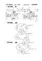
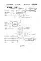
- FIG. 1is a block diagram illustrating typical application for the present invention.
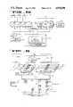
- FIG. 2is a diagram used to illustrate the grouping of cells.
- FIG. 3is another block diagram similar to FIG. 2 used to illustrate the grouping of cells.
- FIG. 4is a diagram used to describe subchannels.
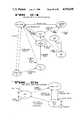
- FIG. 5is a diagram illustrating a plurality of cells; this diagram is used to describe cell group formation employing the present invention.
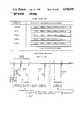
- FIG. 6is a chart illustrating the packet format used with the present invention.
- FIG. 7is a chart illustrating the designation list portion of the packet format of FIG. 6.
- FIG. 8illustrates a series of steps used in forming a group of cell with the present invention.
- FIG. 9is a chart illustrating the code assignments for the three-of-six encoding used with the present invention.
- FIG. 10is a block diagram of the communication and control cell.
- FIG. 11is a block diagram of a portion of the instruction decoding logic used within the processor of the cell of FIG. 10.
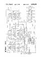
- FIG. 12is a detailed block diagram of the process of FIG. 10.
- FIG. 13is a timing diagram for the processor of FIG. 10; this diagram also shows latches and registers used to provide the pipelining employed by the cell.
- FIG. 14is a block diagram illustrating the presently preferred embodiment of the three-of-six encoder.
- FIG. 15is a block diagram showing the presently preferred embodiment of the three-of-six decoder.
- FIG. 16is a block diagram showing the presently preferred embodiment of the three-of-six code verifier.
- FIG. 17is an electrical schematic of the buffer section of one of the I/O sections.
- FIG. 18is an electrical schematic of the counting and timing functions for an I/O subsection.
- FIG. 19is an electrical schematic of the control and state machine for an I/O section.
- FIG. 20is an electrical schematic for the sample and hold means associated with the I/O subsections.
- FIG. 21illustrates the network formed within an I/O subsection to do digital-to-analog conversion.
- FIG. 22illustrates the network formed within an I/O section for analog-to-digital conversion.
- FIG. 23is an electrical schematic showing the communications portion of an I/O subsection.
- FIG. 24is a state diagram used for the I/O subsections and for transmission contentions.
- FIG. 25is a state diagram for the link level ARQ.
- FIG. 26is a state diagram for primary station connections.
- FIG. 27is a state diagram for secondary station connections.
- FIG. 28is a block diagram for a grouping device.
- FIG. 29is a diagram showing the form in which the system ID is encoded for transmission by the packet and encoded within a cell.
- FIG. 30is a diagram used to describe the operation of the input/output section and semaphore register.
- the systemcomprises a network of cells organized in a hierarchy based on communications needs. Cells ae organized into working "groups" independent of the network hierarchy. Groups of cells generally are used to perform a group function. This function is carried out by the assignment of tasks to cells within the groups. Cells communicate, control and sense information.
- each cellhas a unique identification number annd perform information processing tasks such as: bidirectional communications protocol, input/output, packet processing and analog and digital sensing and control.
- the system comprised of the cellshas the characteristic of storing network configuring information that is distributed throughout the system; and communicates automatically routed messages among cells.
- Each systemalso has a unique identification (ID) which in the presenty preferred embodiment is 48 bits.
- IDunique identification
- itcontains versatile programmable input/outpt I/O circuits with digital versatile programming to configure cells to specific sensing, communication, control and I/O, analog I/O, communication I/O and communications bit rate sensing.
- FIG. 1a simple, typical application is shown based on the use of the present invention in a home.
- the switch 22is used through the present invention to control the light 23.
- the arrangement 20comprises a cell 27 which is connected to the switch 22.
- the cellis also connected to a transceiver 29 which couples data onto the lines 24 and 25.
- Power for the transceiver and cellare provided from the power supply 30 which receives power from the lines 24 and 25.
- the lines 24 and 25are ordinary household wiring (e.g., 110VAC) and the power supply 30, a five volt DC supply.
- the cell 27is preferably an integrated circuit which is described in more detail beginning with FIG. 10.
- the transceiver 29may be any one of many well-known devices for receiving and transmitting digital data and as presently contemplated does not perform any processing on transmitted data.
- the entire arrangement 20may be small enough to fit within an ordinary wallmounted electrical box which normally contains an electrical switch.
- the arrangement 21again may be small enough to fit within a typical electrical outlet box and includes a power supply 31 and transceiver 33 which may be identical in construction to the power supply 30 and transceiver 29, respectively.
- This cell 28is coupled to the transceiver 33 and power supply 31 as well as the solenoid operated power switch 32.
- Cell 28may be identical to cell 27 except for programming and an identification number which shall be discussed later.
- An output from the cell 28controls the solenoid 32 to operate a power switch which in turn connects the light 23 to the power lines 34 and 35.
- the cell 28, as will be seen,can provide a digital or analog output, which can control a rheostat (not shown) or the like, thus enabling the dimming of the light 23.
- the break 26 in the power lines 24 and 25is used to indicate that the power lines 24 and 26 may not necessarily be on the same circuit as power lines 34 or 35.
- the transceiver 29may not necessarily communicate directly with transceiver 33, but rather communication between the transceivers may require linkage through another cell and transceiver which repeats packets sent between the arrangements 20 and 21.
- the transceivers 29 and 33communicate over power lines.
- the transceiversmay communicate with one another in numerous different ways over countless media and at any baud rate. They may, for example, each transmit and receive radio frequency or microwave frequency signals through antennas.
- the transceiverscould be connected to a communications lines, such as an ordinary twisted pair or fiberoptic cable and thus communicate with one another independent of the power lines.
- Other known communications mediummay be employed between the transceivers such as infrared or ultrasonic transmissions. Typical transmission rates are 10K bits per second (KBPS) for power lines. Much higher transmission rates are possible for radio frequency, infrared, twisted pairs, fiberoptic links and other media.
- Cell 27senses the opening or closing of the switch 22, then prepares a packet which includes a message initiating the state of the switch 22; the packet is communicated to the cell 28 through transceiver 29, lines 24 and 25, lines 34 and 35, and transceiver 33.
- the cell 28acknowledges the message by returning a packet to the cell 27 and also acts upon the message it received by turning on or off the light 23 by operating the solenoid controlled power switch 32.
- Each cellhas a unique 48 bit identification number (ID number), sometimes referred to as the cell address.
- ID numbersometimes referred to as the cell address.
- each cellas part of the manufacturing process, receives this permanent and unique ID number. (It cannot be changed following manufacturing.)
- the grouping devicethen accesses the individual cells IDs and assigns a system ID to each cell. In addition, the grouping device configures the cells into groups to perform group related functions.
- cell 27is designated as "A” to indicate that its primary function is to "announce” that is, transmit the state of switch 22 on the network communications lines 24 and 25, and 34 and 35.
- cell 28is designated with the letter “L” since its primary function in FIG. 1 is to "listen” to the network and in particular to listen to messages from cell 27.
- the "A” and “L” designationsare used, particularly in connection with a group formation of multiple cells to indicate an announcer arrangement, such as arrangement 20 and a listener arrangement, such as arrangement 21.
- the cellsthemselves are sometimes referred to as transmitting or receiving data without reference to transceivers.
- the transceiversmay be a simple passive network or simple wires, which couple the input/output of a cell onto a line.
- the I/O section of the cellscan provide output signals that can drive a twisted pair or the like.
- the cells themselvescan function as a transceiver for some media.
- the cells 27 and 28 as will be described subsequentlyare processors having multiprocessor attributes. They may be programmed prior to or after installing to perform their required function, such as an announcer or listener and for grouping combinations.
- a cellis an intelligent, programmable element or elements providing remote control, sensing and/or communications, that when interconnected with other like elements form a communications, control and sensing network or system with distributed intelligence.
- An announceris a source of group messages
- ListenerA listener is a sink of group messages.
- a repeateris a cell which in addition to other functions reads packets from a medium and rebroadcasts them.
- GroupA set of cells which work together for a common function (for example, a switch controlling a set of lights) is referred to as a "group”.
- the group 27has an announcer 37a, listeners 37b, and 37c, and a listener 40.
- a group 38includes an announcer 38a, listeners 38b and 38c and the listener 40.
- FIG. 2illustrates that a single cell (cell 40) may be a listener in two groups. If announcer 37a has a light switch function, it can control lights through cells 37b, 37c and 40. Similarly, a switch associated with announcer 38a can control lights through cells 37c, 37b, and 40.
- a group 42includes announcers 44, 45 and listeners 46 and 47.
- the group 43shares cell 44 with group 42; however, cell 44 is a listener for group 43.
- the group 41shares cell 47 with group 42; cell 47 is an announcer for group 41 and for example, can announce to the listener 48 of group 41.
- Cell 47also operates as a listener for group 42.
- a single cell as shownmay be an announcer for one group and a listener for another group (cells are programmed to perform these functions, as will be discussed). However, as presently contemplated, a single cell cannot announce for more than one group.
- each cellhas three input/output pairs of lines and a select line. Each pair shares a common set of resources.
- the linesmay be used independently for some functions where the required shared resources do not conflict. In other functions, the lines are used as pairs.
- a pair of leads from cell 27are coupled to a light switch and another pair are used for communications from the announcer, cell 27.
- SubchannelIn FIG. 4, a first plurality of cells are shown communicating through a common medium such as a twisted pair 50 (cells are shown as “C”, announcers as “A” and listeners as “L”).
- Thise.g., twisted pair 50
- Thisis defined as a subchannel, that is, a set of cells all of which communicate directly with one another over the same medium.
- a broadcast by any member of the subchannel, such as the cell 49,will be heard by all members of that subchannel over the twisted pair 50.
- a channelcomprises two or more subchannels where all the cells communicate using the same medium.
- another plurality of cellsare shown coupled to twisted pair 52 forming another subchannel.
- cells 56 and 57communicate between one another through a twisted pair 72. They form yet another subchannel.
- the cells associated with the twisted pairs 50, 52 and 72comprise a single channel. It is possible that the twisted pairs 50, 52 and 72 are one continuous twisted pair with one subchannel 50 so far apart from the second subchannel 52 that the only communications between subchannels is over the portion of the twisted pair 72 running between cells 56 and 57.
- the cells 56 and 57are assigned to be "repeaters" in addition to whatever other function they may serve (e.g., announcer or listener).
- a group 55is illustrated in FIG. 4 which comprises an announcer and listener in the two different subchannels.
- Another group 75is illustrated comprising an announcer on one subchannel 51 and subchannel 52, where the subchannels are not part of the same channels since they use different media.
- a gatewayreads packets from two different media and rebroadcasts them.
- a cellmay be a gateway. Communications between channels is through gateway 54.
- an additional subchannel which includes the cell 58is coupled to another medium 51, for example, a common power line.
- the cell 58is shown connected to channel gateway 54 which in turn communicates with the twisted pair 52.
- the gateway 54does not necessarily perform either an announcer or listener function, but rather for the illustrated embodiment, performs only a channel gateway function by providing communication between two different media.
- a subnetworkcomprises all the cells having the same system identification (system ID). For example, all the cells in a single family home may have the same system ID. Therefore, the channels of FIG. 4 may be part of the same subnetwork in that they share the same system ID.
- a full networkmay comprise a plurality of subnetworks each of which has a different system ID; a communications processor is used for exchanging packets between subnetworks.
- the communications processortranslates packets changing their system ID, addressing and other information.
- Two factory buildingsmay each have their own system ID, but control between the two is used by changing system IDs.
- Probe PacketA packet routed by flooding which accumulates routing information as it travels through the network.
- Grouping DeviceA device that controls determination of routes among cells, assigns cells to groups, and assigns function to group members.
- ContentionThe state which exists when two or more cells attempt to transmit a broadcast on the same subchannel at the same time and their signals interfere.
- announcer 60is to be grouped with the listener 65.
- the lines between the cellssuch as line 59 is used to indicate which of the cells can communicate directly with one another, for instance, announcer 60 and cell 61 can communicate with one another.
- Cells 61, 62, 63, 64 and 66of course may be announcers or listeners in other groups, but for purposes of explanation are shown as "C" in FIG. 5.
- announcer 60 and cells 61, 62, and 62all communicate with one another, they are on the same subchannel.
- cells 62, 64, 65 and 66are another subchannel.
- announcer 60 and listener 65are in different subchannels of the channel of FIG. 5 and there are numerous routes by which a message can be passed from announcer 60 to listener 65, for example, through cells 61 and 64 or through cells 62 and 64, etc.
- the announcer 60may be on one circuit which is only coupled to the listener 65 through long lengths of wire running the length of a home and a low impedance bus bar of a circuit breaker panel.
- the high frequency communication messagesmay be sufficiently attenuated through this path to prevent direct communications between cells even though they are physically close to one another.
- each of the cellscan broadcast without interfering with the broadcast of other cells. That is, messages do not interfere with one another.
- the case where some contention occursis dealt with under the protocol section of this application.
- the group of announcer 60 and listener 65is formed by using the grouping device shown in FIG. 28.
- the announcer 60 and listener 65are ordinary cells, not designated to be an announcer and listener.
- Each grouping devicemay be assigned a unique 48 bit system ID at time of manufacture (in the presently preferred embodiment a 48 bit number is used).
- a cellis included with each grouping device. The cell's ID becomes the system ID. This assures that each system has a unique system ID.
- each homehas its own "grouping" device and hence, its own system ID for the subnetworks used in the home. This system ID is used in cell packets for the subnetwork.
- the grouping devicehas available the cell IDs of cells 60 and 65. (Various methods of obtaining cell IDs will be described later.)
- the grouping deviceis connected to cell 60 by communicating through one of its three pairs of input/output (I/O) lines of the cell (or the select pin) and the grouping device reads the 48 bit ID number of the cell 60. (Different methods of determining the cell's IDs are described in the next section.)
- the grouping devicenext generates a random bit binary number which in the presently preferred embodiment is 10 bits. This number functions as a group identification number (also referred to as the group address) for the group comprising the announcer 60 and listener 65.
- the grouping devicechecks this number against other group IDs which it has previously assigned to determine if the group ID has previously been used. If it has been already used it generates another number. (A single grouping device, for instance keeps track of all the group IDs assigned in a single home.)
- the grouping deviceprograms the cell 60 designating it as an announcer.
- the grouping devicemay cause the announcer 60 to broadcast the group number in a special packet which asks all cells in the network to acknowledge the message if they have been designated as a member of this group. This is another way to verify that the group ID has not been used.
- the grouping devicenow determines the ID number of the cell 65. This may be done by connecting the grouping device directly to the cell 65 even before the cell is installed or by other methods discussed in the next section.
- a cell and a groupcan be assigned ASCII names, for example, "porchlight” (cell name) and “exterior lights” (group name). This is used to allow selection of cell IDs or group IDs by accessing the ASCII name.
- the grouping devicecauses the announcer 60 to transmit a probe packet.
- the probe packetcontains the ID of cell 65.
- the packetdirects all cells receiving the packet to repeat it and directs cell 65 to acknowledge the packet.
- Each cell receiving the probe packetrepeats it and adds to the repeated packet its own ID number.
- Each cellonly repeats the packet once (the mechanism for preventing a probe packet from being repeated more than once is described later.)
- the cell 65receives the probe packet through numerous routes, including those which in the diagram appear to be most direct (via cell 62) and those which are longer, for example, via cells 61 and 64. It is assumed that the first probe packet to arrive at cell 65 took the most direct route and is therefore the preferred routing. (Assume that this is via cell 62.) Cell 65 receives a packet which indicates that the probe packet was transmitted by cell 60, repeated by cell 62 and intended for cell 65. The other probe packets received by cell 65 after this first packet are discarded by cell 65.
- Cell 65now transmits an acknowledgement back to announcer 60.
- This packetincludes the routing of the probe package (e.g., repeated by cell 62). The packet directs cell 62 to repeat the packet to confirm its receipt.
- announcer 60After announcer 60 receives the acknowledgement packet for cell 65 it determines that cell 62 must be a repeater.
- the grouping devicescauses announcer 60 to send a repeater assignment packet which includes the unique ID number of cell 62, the group number and a message which informs cell 62 that it is assigned a repeater function for the group. This causes cell 62 to repeat all those packets for the group comprising announcer cell 60 and 65. Another message is sent from announcer 60 under control of the grouping device repeated by cell 62, designating cell 65 as a listener, causing it to act upon messages for the group (cell 65 becomes a group member.) The grouping device assigns members a member number which is stored by member cells.
- Block 68illustrates the broadcasting of the probe packet (e.g., cell 60 transmits the initial probe packet to all cells).
- the packetincludes the address of a destination cell.
- Block 70shows the acknowledgement (reply) to the probe packet from the destination cell (e.g., cell 65). This packet returns the ID numbers of the repeaters contained in the first received probe packet.
- Repeater assignment packetsare sent out by the announcer causing each repeater to rebroadcast packets for the group; this is shown by block 71.
- the destination cellsuch as cell 65 is designated as a listener.
- preinstallation grouping devicesThere may be several types of preinstallation grouping devices, for example, see FIG. 28 for a device which may be used.
- One typeis a device that a manufacturer uses to preassign cells to groups.
- Another type of preinstallation grouping deviceis one that a retailer or other cell vendor may use to assign cells to groups before installation.
- a grouping deviceassigns a cell to a group and assigns the cell's function(s) for that group.
- the grouping devicemay also assign a system ID to the cell.
- the system ID assigned by a preinstallation grouping deviceis not necessarily a unique system ID. (Postinstallation grouping devices assign a unique system ID to each system.)
- One method that may be used by preinstallation grouping devices to generate a system IDis to choose a system ID from a range of the 48 bit address and system ID numbers that have been set aside for use as preinstallation system IDs. Just as the cell IDs in the range 1-1023 have been set aside for use as group IDs and group addresses, the cell IDs in the range 1024-2047 can be set aside for use as preinstallation system IDs.
- preinstallation system IDsare generated by copying a cell ID
- cell IDsshould not be assigned in the range set aside for preinstallation system IDs. Therefore, ID numbers in that range would not be assigned to cells as cell IDs.
- Cellsmay be sold in sets that have been preassigned to a group by the manufacturer.
- the type of preinstallation grouping device used by the manufacturerassigns cells to groups by writing the appropriate codes into the cells' nonvolatile memory.
- the usermay install such a set of cells and it will operate without assignment by a postinstallation grouping device provided that the set of cells may communicate via a single subchannel.
- a usermay assign cells to a group at the time cells are purchased or at any other time before installation. Such cells, unlike the case previously discussed, are not assigned to groups by the manufacturer and are called unassigned cells. Unassigned cells all have the same system ID, a system ID number that has been set aside for use only by unassigned cells.
- the userassigns a set of cells to a group by using a preinstallation grouping device that may be different from the preinstallation grouping device used by a manufacturer.
- such a grouping devicewill operate on one cell at a time.
- the operatorcommands the grouping device to generate a new group ID and system ID and then each cell is connected to the device in turn.
- the operatorcommands the grouping device to assign a cell to the group while the cell is connected to the grouping device.
- the grouping deviceassigns cells the same group ID and system ID until it is commanded by the operator to generate a new group ID and system ID.
- the usermay install such a set of cells and it will operate without use of a postinstallation grouping device provided that the set of cells can communicate via a single subchannel.
- Unassigned cellsmay create a group and assign themselves to the group after installation in the following manner.
- the first announcer cellthat is stimulated via its sensor input (e.g., light switch) controls the group formation process. It chooses a system ID number at random from the range of system ID numbers that have been set aside for preinstallation grouping devices. It chooses a group ID number at random. It then broadcasts the group ID number in a packet that requests a reply from any cells that are members of that group. If the transmitting cell receives any such replies, it chooses another group ID at random. The cell continues this process of selecting a random group ID and testing to see if it is already in use until it finds a group ID that is unused in the system in which it is operating.
- sensor inpute.g., light switch
- An unassigned cell's default configuration information programmed at the factoryidentifies its function as either a listener or an announcer. If the unassigned cell is an announcer, it waits for its sensing input to be stimulated, and when it is stimulated, the cell transmits a packet addressed to a group.
- an unassigned cellIf an unassigned cell is a listener, it listens after power-up for a packet. The cell takes the group ID from the first packet it receives and assigns itself to that group. The cell then sends a reply to the announcer cell. This reply is not an acknowledgement only packet; it is a packet that identifies the cell as a listener in the group and the packet must be acknowledged by the announcer. This assures that all of the listener identification packets will arrive at the announcer even though there will be contention and collisions in the process.
- the cell that transmitted the group announcementbuilds a list of group members as each reply comes in. It then sends a packet to each listener assigning that listener a group member number.
- Unassigned cellsmay be added to existing systems and assigned to a group in a manner similar to the above method discussed in Section 3 above.
- a listenerjoins the system and a group by the same method as in Section 3 above.
- the announcerwaits to be stimulated via its sensor input.
- An unassigned announcerwaits for its first sensor input stimulation or its first received packet. Of those two events, the event that occurs first determines the subsequent actions of the announcer cell.
- the cellIf the cell is stimulated first, it controls a group formation process just as in the above example. If the announcer cell receives a group packet first, it joins that group as an announcer. It then sends a packet to the group announcer requesting configuration information about the group (group size, number of announcers, etc.) and the assignment of a group member number.
- a grouping deviceIn order for a grouping device to go through the steps necessary to form a group or add a cell to a group, it must know the IDs of the cells to be added to the group. The grouping device then uses those cell IDs to address commands to the cells during the grouping process.
- the methods that a user with a grouping device may use to obtain the cell IDsare listed below. Note that a grouping device or other control device's ability to communicate with a cell in the following example may be limited by security procedures if used. The security procedures, limitations on communications and levels of security are not critical to the present invention. The following example assumes that no security procedures are in place. In particular, it may be impossible for a grouping device to communicate with installed cells unless the grouping device has the system key (system ID and encryption keys.)
- the grouping devicemay be connected to an I/O line of the cell package and then sends a message to the cell requesting its ID.
- Physical connectioncan be used to find a cell's ID either before or after the cell is installed.
- Known meanscan be used (e.g., a fuse or a programmed disable command) to allow a user to disable this function in an installed cell to protect the security of the system.
- the usermay use the grouping device or some other selection device to physically select the cell by stimulating a cell input pin that has been designated to serve the selection function.
- the grouping devicecommunicates with the cell through the normal communications channels and sends a broadcast message requesting that all selected cells reply with their ID. Only one cell is selected so only that cell will reply to the request.
- Physical selectioncan be used to find a cell's ID either before or after the cell is installed. Again, a means can be provided to allow a user to disable this feature to protect the security of the system.
- ASCII "groups" and "cell" nameshave been previously assigned to the cells.
- the grouping devicequeries all of the cells in a system to report their group and cell names (ASCII name). The user scrolls through the list of group names by using the grouping device. The user selects the name of the group that is believed to contain the target cell. The grouping device displays the names of all of the cells that are in the group and their assigned tasks (announcer, listener, repeater). The user selects the name of the cell that is believed to be the target cell.
- the grouping deviceprompts the user to activate the announcer by stimulating its input. For example; if the cell is attached to a light switch, the user turns the switch on and off. The cell sends announcement packets to the group. The grouping device listens to the communications channel and discovers the group and member numbers or other codes of the activated announcer.
- the grouping devicesends packets to the cell (using the group and member numbers for addressing) commanding it to toggle its output. For example, if the cell controls a light, the light will flash on and off. This allows the user to verify that he has selected the correct cell.
- the grouping devicesends a packet (using group and member numbers for addressing) to the target cell with a command for the target cell to return its cell ID.
- the grouping devicenow knows the target ID and can proceed with the group assignment process.
- Querying namesis used to find a cell's ID before or after the cell is installed.
- This methodis used in a network in which group and cell ASCII names have been assigned.
- the usercommands the grouping device to wait for the next group announcement. Then the user stimulates the announcer in the group of interest. For example, if the announcer is a light switch, the user throws the switch.
- the grouping devicehears the announcement packet and extracts the group ID from it.
- the usermay verify that this group ID is for the desired group by causing the grouping device to send packets to all of the group listeners commanding them to toggle their outputs.
- the userverifies that it is the desired group by observing the actions of the listener cells (for example, if the group consists of lighting controls, the light flashes).
- the grouping devicebroadcasts a packet to the group requesting that each cell reply with its cell name until the cell of interest is found.
- the userselects that name and the grouping device, knowing that cell's ID, can proceed with the group assignment process.
- the ID of the cellmay be verified before proceeding with the grouping procedure.
- the following procedureis used to verify that the ID is for the target cell.
- the grouping deviceprompts the user to activate the announcer by stimulating its input. For example: if the cell is attached to a light switch, the user turns the switch on and off. The grouping device is then able to discover the group address and member number of the cell.
- the grouping devicesends packets to the cell (using the group and member numbers, for addressing) commanding it to toggle its output. For example, if the cell controls a light, the light will flash on and off. This allows the user to verify that he has selected the correct cell.
- This methodis used in a network in which no group or cell ASCII names have been assigned but announcers and listeners have been assigned.
- the grouping devicesends a packet to all cells in the network commanding each announcer to broadcast a packet containing its ID the next time it is stimulated.
- the grouping devicethen prompts the user to stimulate the announcer by activating its sensed device; for instance, turn on a light switch for a light switch announcer. Since the user will stimulate only one announcer, the grouping device will receive only one packet with a cell ID.
- This methodis used in a network in which no group or cell names have been assigned.
- the grouping devicebroadcasts a packet that queries cells that are listeners to reply with their ID.
- the grouping deviceneeds to limit the number of cells replying so the packet contains an ID bit mask to limit replies to a subset of the possible cell IDs.
- the grouping devicehas developed a list of listener IDs, it allows the user to toggle each listener, causing the listener cell to turn its output on and off. The user continues through the list of listener cells until he observes the target cell toggling its output. The user has then identified the cell to the grouping device and it can proceed with the grouping operation.
- Each packet transmitted by a cellcontains numerous fields. For example, a format used for group announcements is shown in FIG. 6. Other packet formats are set forth in Appendix A. Each packet begins with a preamble used for synchronizing the receiving cells' input circuitry (bit synch). The particular preamble code used in the currently preferred embodiment is described as part of the three-of-six combinatorial codes (FIG. 9). A flag field of 6 bits begins and ends each of the packets. The flag field code is also described in FIG. 9.
- each of the cellsreads-in the entire packet, does a cyclic redundancy code (CRC) calculation on the packet except for the contention timer field and compares that result with the CRC field of the received packet.
- the ALU 102 of FIG. 12has hardware for calculating the packet CRC and CRC registers 130 for storing intermediate results. If the packet CRC cannot be verified for an incoming packet, the packet is discarded.
- the packet CRC fieldis 16 bits as calculated, then converted into 24 bit fields for transmission in a 3-of-6 code using the encoding of FIG. 9. (For the remainder of discussion of packet fields in this section, the field length is described prior to encoding with the 3-of-6 combinatorial codes of FIG. 9.)
- the CRCis a CCITT standard algorithm (X 16 +X 12 +X 5 +1).
- the system IDis a 32 bit field as currently preferred.
- the other 16 bits of the 48 bit system IDare included in the CRC calculation but not transmitted as part of the packet (FIG. 29).
- the link address fieldis a 48 bit field. When this field is all zeroes the packet is interpreted as a system wide broadcast which is acted upon by all the cells. For instance, a probe packet has an all zero field for the link address. Group addresses are dcontained within the link address. For group addresses the first 38 bits are zero and the remaining 10 bits contain the group address. (The cell ID numbers assigned at the factory mentioned earlier range from 1024 to 2 48 since 2 10 addresses are reserved for groups.) The link address, in some cases, is an individual's cell's address. (For example, when a cell is being assigned the task of repeater or listener.)
- the contention timeris a 10 bit field with an additional 6 bits for a CRC field (or other check sum) used to verify the 10 bits of the timer field.
- Each cell which repeats a packetoperates upon this field if the cell must wait to transmit the packet. If packets are being transmitted by other cells a cell must wait to transmit its packet, the time it waits is indicated by counting down the contention timer field.
- the rate at which this field is counted downcan be programmed in a cell and this rate is a function of the type of network.
- the fieldstarts with a constant which may be selected by the type of network.
- Each cell repeating the packetcounts down from the number in the field at the time the packet is received.
- the number in the contention fieldreflects the sum of the times waited subtracted from a constant (e.g., all ones).
- the contention timer fieldreaches all zeroes, the cell waiting to transmit the packet discards the packet rather than transmit it. This prevents older packets from arriving and being interpreted as being a new packet.
- the contention timerhas its own 6 bit CRC field. If the contention timer field were included in the packet CRC, the packet CRC could not be computed until a packet could actually be transmitted. This would require many calculations in the last few microseconds before a transmission. To avoid this problem a separate CRC field is used for the contention timer field. If the contention timer field cannot be verified by its 6 bit CRC, the packet is discarded.
- the hop count fieldrecords the number of hops or retransmissions that a packet takes before arriving at its destination.
- This 4 bit fieldstarts with a number which is the maximum number of retransmissions allowed for a particular packet and is decremented by each cell repeating a packet. For example, in a packet originated by a group announcer the starting "hop" count is the maximum number of retransmissions that the packet must undergo to reach all of the cells in a group. When this field becomes all zeroes, the packet is discarded by the cell, rather than being retransmitted Therefore, 16 hops or retransmissions is the limit as currently implemented.
- the link control fieldprovides the link protocol and consists of 8 bits. This field is discussed in a subsequent section covering other layers of the protocol.
- the random/psuedo random number fieldcontains an 8 bit random number which is generated for each packet by the cell originally transmitting the packet. This number is not regenerated when a packet is repeated. This number is used as will be explained in conjunction with FIG. 8 to limit rebroadcasting of probe packets; it also may be used in conjunction with encryption where the entire packet is to be encrypted.
- the network control field(4 bits) indicates routing type or packet type, for instance, network control, group message, probe message, etc.
- the source address fieldd(variable size) contains, by way of example, the 48 bit ID number of the cell originating a packet. For a probe packet this field contains the ID number of the announcer. For an acknowledgement the field contains the ID of the listener. For a packet addressed to a group, this field contains the source cell's group member number.
- the destination listis described in conjunction with FIG. 7.
- the message fieldis variable in length and contains the particular message being transmitted by the packet. Typical messages are contained in Appendix B. In the case of a probe packet the field includes the routing; that is, each cell repeating includes its ID number to this field. The messages, once a group is formed, will, for instance, is used by announcer 60 to tell listener 65 to turn-on a light, etc.
- the encryption fieldwhen used, contains 16 bits used to verify the authenticity of an encrypted packet typically this portion of a packet is not changed when a packet is repeated.
- Well-known encryption techniquesmay be used.
- the bracket 99 of FIG. 6represents the portion of a packet which remains unaltered when a packet is repeated. These fields are used to limit repeating as will be described in conjunction with FIG. 8.
- the destination list field of the packet of FIG. 6is shown in FIG. 7.
- the destination listbegins with a 4 bit field which indicates the number of members in a group designated to receive a message in the packet. Therefore the packet can be directed to up to 16 members of a group.
- the number of each of the members within the groupis then transmitted in subsequent 8 bit fields.
- the group number contained in the link address and member number contained in the destination listforms an address used to convey messages once the group is formed. If the destination number is zero, the packet is addressed to all members of the group. For some packet types this field contains the ID of the receiving cell (see Appendix A).
- the probe packetsare repeated only once by each of the cells after the packet is initially broadcast.
- a special mechanism programmed into each of the cellsallows the cells to recognize packets which it has recently repeated.
- each celltransmits, or retransmits a packet, it calculates a packet CRC field which precedes the end flag. For packets that are repeated, a new CRC is needed since at least the hop count will change, requiring a new packet CRC field for the packet. This CRC field is different from the CRC field discussed in the next paragraph.
- a repeater CRC numberis calculated for the fields extending from the beginning of the link control to the end of the destination list as indicated by bracket 99 of FIG. 6.
- a cellrebroadcasts a packet it stores the 16 bit repeater CRC results in a circular list of such numbers if the same number is not already stored. However, the packet is repeated only if the circular list does not contain the repeater CRC results calculated for the field 99.
- the CRCis computed for the field 99. This is shown by block 73a of FIG. 8. This number is compared with a list of 8 numbers stored within the RAM contained within the cell indicated by block 73b. If the number is not found within the stored numbers, the new repeater CRC results are stored as indicated by block 73c and the packet is repeated. On the other hand, if the number is found then the packet is not repeated. As presently implemented, 8 numbers are stored in a circular list, that is, the oldest numbers are discarded as new ones are computed.
- the use of the repeater CRC calculation associated with the field 99 and the use of the circular listwill prevent repeating of a previously rebroadcasted packet. Note that even if an announcer continually rebroadcasts the same sequence of messages, for example, as would occur with the continuous turning on and turning off of a light, a cell designated as a repeater will rebroadcast the same message since the packet containing messages appears to be different. This is true because the random number sent with each of the identical messages will presumably be different. However, in the instance where a cell receives the same message included within the same field 99 (same random number), the packet with it message will not be rebroadcast. This is particularly true for probe packets. Thus, for the establishment of groups discussed above, the broadcast probe packets quickly "die out" in the network, otherwise they may echo for some period of time, causing unnecessary traffic in the network.
- encodingis employed to embed timing information within the data stream.
- One widely used encoding methodis Manchester coding. Manchester or other coding may be used to encode the packets described above, however, the coding described below is presently preferred.
- a three-of-six combinatorial codingis used to encode data for transmission in the presently preferred embodiment. All data is grouped into 4 bit nibbles and for each such nibble, six bits are transmitted. These six bits always have three ones and three zeroes. The transmission of three ones and three zeroes in some combination in every six bits allows the input circuitry of the cells to quickly become synchronized (bit synch) and to become byte synchronized as will be discussed in connection with the I/O section. Also once synchronized (out of hunt mode) the transitions in the incoming bit stream are used to maintain synch.
- the righthand column of FIG. 9lists the 20 possible combinations of 6 bit patterns where 3 of the bits are ones and 3 are zeroes.
- the corresponding 4 bit pattern assigned to the three-of-six patternis shown. For example, if the cell is to transmit the nibble 0111, it is converted to the bit segment 010011 before being transmitted. Similarly, 0000 is converted to 011010 before being transmitted. When a cell receives the 6 bit patterns, it converts them back to the corresponding 4 bits patterns.
- the three-of-six pattern 010101is used as a preamble for all packets.
- the flags for all packetsare 101010.
- the preamble and flag patternsare particularly good for use by the input circuitry to establish data synchronization since they have repeated transitions at the basic data rate.
- the two three-of-six patterns not assignedcan be used for special conditions and instructions.
- a cellprepares a packet generally in integral number of bytes and each nibble is assigned a 6 bit pattern before transmission. The preamble and flags are then added.
- the circuitry for converting from the 4 bit pattern to the 6 bit patterns and conversely, for converting from 6 bit patterns to the 4 patternsis shown in FIGS. 14 and 15.
- each cellincludes a multiprocessor 100, input/output section 107-110, memory 115 and associated timing circuits shown specifically as oscillator 112, and timing generator 111. Also shown is a voltage pump 116 used with the memory 115.
- This cellis realized with ordinary integrated circuits.
- the multiprocessor 100may be fabricated using gate array technology, such as described in U.S. Pat. No. 4,642,487.
- the preferred embodiment of the cellcomprises the use of CMOS technology where the entire cell of FIG. 10 is fabricated on a single silicon substrate as an integrated circuit.
- the multiprocessor 100is sometimes referred to in the singular, even though, as will be described, it is a multiprocessor, specifically four processors.
- the multiprocessor 100is a stack oriented process having four sets of registers 101, providing inputs to an arithmetic logic unit (ALU) 102.
- the ALU 102comprises two separate ALU's in the presently preferred embodiment.
- the memory 115provides storage for a total of 64KB in the currently preferred embodiment, although this particular size is not critical.
- One portion of the memoryis used for storing instruction (ROM code 115a).
- the next portion of the memoryis a random-access memory 115b which comprises a plurality of ordinary static memory cells (dynamic cells can be used).
- the third portion of the memorycomprises an electrically erasable and electrically programmable read-only memory (EEPROM) 115c.
- the EEPROM 115cemploys memory devices having floating gates. These devices require a higher voltage (higher than the normal operating voltage) for programming and erasing. This higher potential is provided from an "on-chip" voltage pump 116.
- the entire address space for memory 115 addressed through the ALU 102awhich is one part of the ALU 102.
- the ROM 115astores the routines used to implement the various layers of the protocol discussed in this application. This ROM also stores routines needed for programming the EPROM 115c.
- the application program for the cellis stored in ROM 115a and, in general, is a routine which acts as a "state machine” driven by variables in the EEPROM 115c and RAM 115b.
- RAM 115bstores communications variables and messages, applications variables and "state machine” descriptors.
- the cell ID, system ID and communications and application parameters(e.g., group number, member number, announcer/repeater/listener assignments) are stored in the EEPROM 115c.
- the portion of the EEPROM 115c storing the cell IDis "write-protected" that is, once programmed with the cell ID, it cannot be reprogrammed
- the input/output section of the cellcomprises four subsections 107, 108, 109 and 110. Three of these subsections 107, 108 and 109 have leads 103, 104, and 105 respectively for communicating with a network and/or controlling and sensing devices connected to the cell.
- the remaining subsection 110has a single select pin 106 which can be used to read in commands such as used to determine the cell's ID. As presently implemented, the subsection 110 is primarily used for timing and counting.
- the input/output sectionis addressed by the processor through a dedicated address space, and hence, in effect appears to the processor as memory space. Each I/O subsection can be coupled to each of the subprocessors.
- the I/O sectionmay be fabricated from well-known circuitry; the presently preferred embodiment is shown in FIGS. 17 through 23.
- the cell of FIG. 10also includes an oscillator 112 and timing generator 111, the latter provides the timing signals particularly needed for the pipelining shown in FIG. 13. Operation at a 16 mHZ rate for the phases 1-4 of FIG. 13 is currently preferred, thus providing a 4 mHz minor instruction cycle rate. Other well-known lines associated with the cell of FIG. 10 are not shown (e.g., power).
- the currently preferred embodiment of the processor 100is shown in FIG. 12 and includes a plurality of registers which communicate with two ALU's 102a and 102b. (Other processor architectures may be used such as one having a "register" based system, as well as other ALU and memory arrangements.)
- the address ALU 102aprovides addresses for the memory 115 and for accessing the I/O subsections.
- the data ALU 102bprovides data for the memory and I/O section.
- the memory outputin general is coupled to the processor registers through registers 146 to DBUS 223.
- the 16-bit ABUS 220provides one input to the address ALU 102a.
- the base pointer registers 118, effective address registers 119 and the instruction pointer registers 120are coupled to this bus. (In the lower righthand corner of the symbols used to designate these registers, there is shown an arrow with a designation "x4". This is used to indicate that, for example, the base pointer register is 4 deep, more specifically, the base pointer register comprises 4 16-bit registers, one for each processor. This is also true for the effective address registers and the instruction pointer registers.)
- the BBUS 221provides up to a 12 bit input to the ALU 102a or an 8 bit input to the data ALU 102b through register 142.
- the 4 deep top of stack registers 122, stack pointer registers 123, return pointer registers 124 and instruction registers 125are coupled to the BBUS.
- the CBUS 222provides the other 8-bit input to the ALU 102 through register 143.
- the CBUSis coupled to the instruction pointer registers 120 , the 4 deep top of stack registers 122, the four carry flags 129, and the 4 deep CRC registers 130 and the 4 deep next registers 131.
- the MBUScoupled to the output of the memory, can receive data from the output of the ALU 102b through register 145b, or from the memory or I/O sections (107-110).
- This bus through register 146 and the DBUS 223provides inputs to registers 118, 119, 120, 122, 123, 124, 125, 130, 131 and to the carry flags 129.
- the ALU 102bincludes circuitry for performing CRC calculations. This circuitry directly connects with the CRC registers 130 over the bidirectional lines 133.
- the top of stack registers 122are connected to the next registers 131 over lines 138. These lines allow the contents of register 122 to be moved into registers 131 or the contents of register 131 to be moved into registers 122.
- a bidirectional, (simultaneous) swap of data between these registersis not implemented.
- Four bits of data from the output of the memorymay be returned directly either to the instruction pointer registers 120 or the instruction registers 125 through lines 139.
- the data in any one of the stack pointer registers 123 or any one of the return pointer registers 124may be directly incremented or decremented through circuit 127.
- Both ALU's 102a and 102bcan pass either of their inputs to their output terminals, can increment and can add their inputs.
- ALU 102bin addition to adding, provides substracting, shifting, sets carry flags 124 (when appropriate), ANDing, ORing, exclusive ORing and one complement arithmetic.
- the ALU 102b in a single stepalso can combine the contents of next registers 131 and CRC registers 130 (through paths 222 and 133) and combine it with the contents of one of the top of stack registers 122 to provide the next number used in the CRC calculations.
- ALU 102bperforms standard shifting and provides a special nibble feature allowing the lower or higher four bits to be shifted to a higher or lower four bits, respectively.
- ALU 102bperforms a 3-of-6 encoding or decoding described in Section F.
- control contact padmay be provided to disable internal memory. By activating the control contact the internal memory is disable and the data over ADBUS and MBUS is used by the processors. This allows the use of a memory that is external to the cell. It is assumed that the additional contact pads may not be available for use when the cell is in an inexpensive package. These additional contacts may be accessed by wafer probe contacts or from pins in packages that have more than the minimum number of pins.
- the cell as manufacturedrequires an initialization program. At wafer probe time the external memory is used for several purpose, one or which is to test the cell. Another use is to provide a program to write the cell ID into the EEPROM during the manufacturing process. Any necessary EEPROM instructions to allow power up boot when the cell is later put in use may be added at this time.
- Initialization programs and test programsare well-known in the art.
- memory fetchesoccur when the ALU 102a provides a memory address.
- the memory addessis typically a base address or the like on the ABUS from one of the base points in registers 118, effective address registers 119 or instruction pointer register 120 combined with an offset on the BBUS from the stack pointer register 123, return pointer register 124, top of stack registers 122 or the instruction registers 125.
- Calculations in the ALU 102bmost typically involve one of the top of stack registers 122 (BBUS) and the next registers 131 (CBUS) or data which may be part of an instruction from one of the instruction registers 125.
- the processoroperates with the output of the memory being coupled to the DBUS 223 through register 146
- the processorcould also be implemented with data being coupled directly to the input of ALU 102b.
- the function performed by some of the other registers, such as the effective address registers 119can be performed by other registers, although the use of the effective address registers, and for example, the CRC registers, improve the operation of the processor.
- a base pointeris provided by one of the registers 118, 119 or 120 with an offset from one of registers 122, 123, 124 or 125.
- the address ALU 120aprovides these addresses.
- the ALU 120boperates on the contents of the top of stack and next register; there are exceptions, for example, the instruction register may provide an immediate input to the ALU 102b. Specific addressing and other instructions are described below.
- the processoris effectively a multiprocessor (four processors) because of the multiple registers and the pipelining which will be described in conjunction with FIG. 13.
- one advantage to this multiprocessor operationis that interrupts are not needed, particularly for dealing with input and output signals.
- the multiprocessor operationis achieved without the use of separate ALUs for each processor.
- economies of layoutare obtained by using two ALUs, (102a and 102b) however, only one of the ALUs operates at any given time. (Note the BBUS provides an input to both ALUs.) Therefore, the multiprocessor operation of the present invention may be obtained using a single ALU.
- the processing systemhas four processors sharing an address ALU, a data ALU and memory.
- a basic minor cycletakes four clock cycles for each processor.
- the ALUstake one clock cycle and the memory takes one clock cycle.
- the minor cycles for each processorare offset by one clock cycle so that each processor can access memory and ALUs once each basis minor cycle. Since each processor has its own register set it can run independently at its normal speed. The system thus pipelines four processors in parallel.
- Each register of FIG. 12is associated with one of four groups of registers and each group facilitates the multiprocessor operation and is associated with a processor (1-4) of FIG. 13.
- Each of the four groupsincludes one base pointer register, effective address register, instruction pointer register, top of stack register, stack pointer register, return pointer register, instruction register, CRC register, next register, and a carry flag.
- Each related group of registerscorresponds to one of the four processors.
- Each processorexecutes instructions in minor cycles, each minor cycle consisting of four clock cycles. During the first clock cycle a processor will gate the appropriate registers onto the ABUS, BBUS and CBUS. In the next clock cycle the ALUs will be active generating data from their inputs of the ABUS, BBUS and CBUS.
- Memory or I/Owill be active during the third clock cycle, with the address coming from the ALU 102a and data either being sourced by memory or the ALU 102b.
- the fourth and final clock cyclewill gate the results from memory or the ALU 102b into the appropriate register via the DBUS.
- a processorcan be viewed as a wave of data propagating through the sequence described above. At each step the intermediate results are clocked into a set of pipeline registers. By using these pipeline registers it is possible to separate the individual steps in the sequence and therefore have four steps executing simultaneously. The four processors can operate without interfering with one another even though they share the ALUs, memory, I/O and many control circuits.
- FIG. 11The control of a processor including the pipelining is best understood from FIG. 11.
- a processorthere is a 3 bit counter and an instruction register. These are shown in FIG. 11 as counters 137a through 137d, each of whih is associated with one of the instruction registers 125a through 125d, respectively.
- Each of the instruction registersis loaded through the DBUS. As an instruction register is loaded, the instruction is coupled to a PLA 212. This PLA determines from the instruction how many minor cycles are required to execute the instruction and a 3 bit binary number is then loaded into the counter 113a or 113b or 113c or 113d, associated with the instruction register 125a, or 125b, or 125c or 125d being loaded.
- the binary number 010(indicating three minor cycles) is loaded into couter 137c. (Up to 8 minor cycles can be used for a given instruction, however, only up to 6 minor cycles are used for any of the instructions in the currently preferred embodiment.)
- the count value "000"is used to cause a new instruction to be fetched.
- the output of the PLAcontrols the operation of the processors. More specifically: lines 213 control data flow on the ABUS, BBUS and CBUS; lines 214 control the ALU 102; lines 215 control the memory; (and, as will be described later I/O operation of subsections 107, 108, 109 and 220) and lines 216 control data flow on the DBUS.
- the specific outputs provided by the PLA 136 for a given instructionis best understood from the instructions set, set forth later in this application. The action taken by the processors to execute each of the instructions is described with the instruction set.
- the outputs from the PLA on lines 213are coded directly to the devices controlling data flow on the ABUS, BBUS, and CBUS.
- the signals controlling the ALUare coupled through a one clock phase delay register 217 before being coupled to the ALU via the lines 214. Since all the registers 217 are clocked at the same rate, the register 217 performs delay functions as will be described.
- Those signals from the PLA 136 used for memory controlare coupled through two stages of delay registers 217 before being coupled to the memory, thus the signals on lines 215 are delayed for two clock phases related to the signals on lines 213.
- the control signals for the DBUS after leaving the PLA 136are coupled through 3 sets of delay registers 217 before being coupled to the lines 216 and therefore are delayed three clock phases related to those on lines 213.
- the registers 217are clocked at a 6 mHz rate, thus when the PLA 136 provides output control signals for a given instruction (e.g., contents of instruction register 125a) the control signals during a first clock phase are coupled to lines 213, during a second clock phase, lines 214; during a third clock phase, 215; and during a fourth clock phase to lines 216.
- the contents of the counter 137a and the instruction register 125aare coupled to the PLA 136.
- the contents of the counter 137b and instruction register 125bare coupled to the PLA 136 and so on for the third and fourth clock phases.
- the control signals on lines 213used to carry out the first clock phase of the CALL instruction which is the inputs to the ALUs.
- the other control linesare controlling the ALU, the memory and the DBUS of other processors, for different instructions in the pipelines.
- the count in counter for 137b and the instruction in register 125bare coupled to the PLA 136.
- the signals on lines 213now control the ABUS, BBUS and CBUS inputs to the ALUs for the second processor to carry out the instruction contained in register 125b.
- the signals on lines 214control the first processor and the ALU to perform the functions needed to carry out the second clock phase of the CALL instruction contained in register 125a. (Note a delay equal to one phase was provided by register 217).
- the signals on lines 213control the ABUS, BBUS, and CBUS for the third processor to carry out the instruction contained in register 125c;
- the signals on lines 214control the ALU to carry out the instruction contained in register 125b, and the signals on lines 215 control the memory to carry out the instructions in register 125a for the first processor.
- the instruction from register 125d, along with the count in counter 137dare coupled to the PLA 136.
- the signals on lines 213control the ABUS, BBUS and CBUS to carry out the instruction contained within register 125d fourth processor; the signals on lines 214 control the ALU to carry out the instruction in register 125c for the third processor; the signals on lines 215 control the memory to carry out the instruction in register 125b for the second processor; and the signals on lines 216 control the DBUS to carry out the instruction in register 125a for the first processor.
- each of the four processorsmay simultaneously execute an instruction where each of the instructions has a different number of cycles.
- the control signals reaching the imaginary line 219 for any given clock cyclerepresent control signals for four different instructions and for four different processors.
- the control signals associated with the first processor during a first cycleappear on lines 213; during a second cycle on lines 214; during a third cycle on lines 215; and during a fourth cycle on lines 216.
- the control signals needed by the second processorfollow behind; those needed by the third and fourth processors following behind those used by the second processor.
- FIG. 13The pipelining of the signals is illustrated in FIG. 13.
- the multiprocessor operation of the processor 100 of FIG. 10is shown in FIG. 13 as four processors, processors 1, 2, 3 and 4. Each one of the groups of registers is associated with one of the processors.
- the four phases of a single instruction cycleare shown at the top of FIG. 13.
- registers 101are used to indicate that the contents from the specific registers called for in an instruction are placed on the ABUS, BBUS and CBUS.
- the registersare 118, 119 and 120 on the ABUS; 122, 123, 124 and 125 on the BBUS; 120, 122, 129, 130 and 131 on the CBUS.
- signals previously stored in the group 1 registersare gated from the registers onto the ABUS, BBUS and CBUS. While this is occurring, signals associated with the group 2 registers are gated from the registers 141, 142, 143 into the ALU 102a and 102b. This is shown in FIG. 13 as processor 2 under the first phase column. Simultaneous signals are gated from registers 145a and 145b into the memory for group 3 registers for processor 3. And, finally, during this first phase, signals associated with the group 4 registers are gated from registers 146 onto the DBUS. During the second phase, signals associated with a group 1 registers are coupled from the ALU to registers 145.
- the data associated with group 2 registersare coupled to memory.
- the data associated with the group 3 registersis coupled from the register 146 onto the DBUS.
- Those associated with the group 4 registersare gated onto the ABUS, BBUS and CBUS. And, similarly, during the third and fourth phase of each instruction cycle, this pipelining continues as shown in FIG. 13, thus effectively providing four processors.
- each instruction of the processoris set forth, along with the specific registers and memory operations. Lower case letters are used below to indicate the contents of a register. For example, the contents of the instruction register are shown as "ip”.
- the registers and flagsare set forth below with their correlation to FIG. 12.
- the top element of the return stackis also addressable as a register, even though it is physically located in RAM.
- the ALU 102bcontains means for encoding four bit nibbles into six bit words for transmission (encoder of FIG. 14) and for decoding six bit words into the four bit nibbles (decoder of FIG. 15). Both the encoder and decoder use hardwired logic permitting the conversion to be performed very quickly in both directions. Moreover, there is a circuit shown in FIG. 16 to verify that each six bit word received by the cell is in fact a three-of-six code, that is, three zeroes and three ones (FIG. 9).
- "logical OR.) These equations can be implemented with ordinary gates.
- the decoder of FIG. 15is shown in a similar format. This time the six bits of the encoded data are shown in register 142. The decoded four bits of data are shown in the register 145. To implement the pattern assignment shown in FIG. 9, the E 0 bit is coupled directly to the register 145 and becomes D 0 . The E 5 bit is coupled directly to the register 145 and becomes the D 3 bit. Logic circuits 154 and 155 provide the bits D 2 and D 1 , respectively.
- Circuit 154is coupled to receive the bits E 0 , E 3 , E 4 and E 5 while the circuit 155 receives E 0 , E 1 , E 3 , and E 5 (E 2 is not used to provide the D 0 through D 3 bits.) (Some of the six bit patterns are not used and others are used for synchronization and thus do not require conversion into a data nibble).
- the circuits 154 and 155are constructed from ordinary logic gates and implement the equations shown. The symbol " " represents the exclusive OR function in the equations.
- the circuit of FIG. 16verifies that the received six bit words do not contain three zeros and three ones.
- the encoded wordsare shown coupled from the top of stack register 122 into the two full adders, 157 and 158. These adder stages are contained within the ALU 102b. Each adder receives an X, Y and carry input and provides a sum and carry output. These ordinary adder stages are each coupled to receive one bit of the encoded word as shown. (Any coupling of each bit to any input of address 157 and 158 may be used.)
- the carry outputs of the adders 157 and 158are coupled to the exclusive OR gate 159; the sum outputs of the adders 157 and 158 are coupled to the exclusive OR gate 160.
- the output of the gates 159 and 160are coupled to the input terminals of an AND gate 161. If the output of this AND gate is in its high state the word in the register 102 contains three ones and three zeros. Otherwise, the output of the gate 161 is in its low state (abort condition). The incoming packets are checked to determine that each six bit word is valid, while it is decoded into the four bit nibbles.
- the I/O sectionincludes a plurality of circuit elements such as a ramp generator, counter, comparator, etc., which are interconnected in different configurations under software control. Examples of this are shown below for the analog-to-digital (A to D) and digital-to-digital (D to A) operations. These elements with their software configurable interconnections provide great flexibility for the cell, allowing it to perform many tasks.
- the entire I/O sectionis preferably fabricated on the same "chip" which includes the processor.
- each of the cellsinclude four input/output I/O subsections; three of the subsections 107, 108, and 109 each have a pair of leads, identified as Pin A and Pin B.
- the fourth subsection 110has a single "read only" pin 106. Any of the four subsections can communicate with any of the four subprocessors. As shown in FIG. 12, this is easily implemented by connecting the address bus (ADBUS) and the memory bus (MBUS) to each of the four I/O subsections. Use of the MBUS through the register 146 to the DBUS allows the I/O subsections to communicate with the processor registers.
- ADBUSaddress bus
- MBUSmemory bus
- Each Pin A and Pin Bcan receive and provide TTL level signals and is tristated. In the currently preferred embodiment, each pin can sink and source approximately 40 milliamps (except for pin 106). All the Pin A's can be programmed to provide an analog output signal and a digital-to-analog converter is included in three of the I/O subsections 107, 108 and 109 to provide an analog output on Pin B. An analog input signal on any of the Pin B's can be converted to a digital count since three of the I/O subsections include A to D converters coupled to these pins. Each pin pair (Pin A and Pin B) can operate as a differential amplifier for input signals, a differential receiver, and a differential transmitter and a differential voltage comparator.
- the I/O subsectionscan be used to perform many different functions, from simple switching to, by way of example, having two pin pairs coupled to drive the windings of a stepping motor.
- circuits shown in FIGS. 17-23are repeated in subsections 107, 108 and 109. Those circuits associated with Pin A and Pin B (such as the buffer sections of FIG. 17) are not fully contained in the I/O subsection 110. Only sufficient buffering to allow data to be read on Pin 106 is needed.
- outgoing datais coupled to Pin A through the buffer 163.
- outgoing datais coupled to Pin B through the buffer 164 after the data passes through the I/O control switch 165.
- This outgoing datais coupled to Pin A from the register 206 of FIG. 23 through gate 208 of FIG. 19.
- the control switch 165is used to enable outputs to Pin A through the buffer 163, when enable A (EN.A) is high (line 166).
- the switchenables the output to Pin B when enable B (EN.B) is high (line 167) and enables outputs to both pins (with the output to Pin B being inverted) when enable RS-485 is high (line 168).
- the outgoing analog signal to Pin Ais provided through the switch 175 when the enable analog output signal is high.
- Incoming signals to Pin Aare coupled to one input terminal of the differential amplifier 169.
- the other terminal of this signalreceives a reference potential (e.g., 2.5 volts).
- This amplifieralso includes the commonly used hysteresis mode to prevent detection of noise. This mode is activated when the enable hysteresis (Pin A) signal coupled to amplifier 169 is high.
- the output of amplifier 169is coupled to a transition detection circuit 171 which simply detects each transition, that is, a zero to one, or one to zero.
- the inputs to Pin Bare coupled to one terminal of a differential amplifier 170 which may be identical to amplifier 169.
- the amplifier 170receives the enable hysteresis (Pin B) signal.
- the other input to amplifier 170(line 176) can be coupled to receive one of several signals. It can receive a DC signal used for voltage comparisons, a ramp which shall be discussed later, the signal on Pin A for differential sensing, or a reference potential (e.g., 2.5 volts).
- the output of the amplifier 170can be inverted through the exclusive OR gate 177 for some modes of operation.
- a transition detector 172is associated with the Pin B inputs, again to detect transitions of zero to one or one to zero.
- Each of the cellsincludes a timing generator (RC oscillator) for providing a 16 mHz signal.
- This signalis connected to a rate multiplier 178 contained in the I/O section (FIG. 18).
- the multiplier 178provides output frequencies to each I/O subsection.
- This multiplierprovides a frequency f 0 equal to: ##EQU1##
- the loaded valueis a 16 bit word loaded into a register of a rate multiplier 178.
- the rate multipliercomprises four 16-bit registers and a 16-bit counter chain.
- Four logic circuitsallow selection of four different output signals, one for each subsection.
- Two bus cycles (8 bits each)are used to load the 16 bit words into the register of the rate multiplier 178.
- a relatively wide range of output frequenciescan be generated. These frequencies are used for many different functions as will be described including bit synchronization.
- the output of the multiplier 178 in each of the subsectionis coupled to an 8 bit counter 179.
- the countercan be initially loaded from a counter load register 180 from the data bus of the processors. This register can, for example, receive data from a program.
- the count in the counteris coupled to a register 181 and to a comparator 182.
- the comparator 182also senses the 8 bits in a register 183. The contents of this register are also loaded from the data bus of the processors. When a match between the contents in the counter and the contents of register 183 is detected by comparator 182; the comparator provides an event signal to the state machine of FIG. 19 (input to multiplexers 190 and 191).
- the contents of the counter 179can be latched into register 181 upon receipt of a signal from the state machine (output of the execution register 198 of FIG. 19). The same execution register 198 can cause the counter 179 to be loaded from register 180. When the counter reaches a full count (terminal count) a signal is coupled to the state machine of FIG. 19 (input to multiplexers 190 and 191).
- the processor MBUScommunicates with registers 185 and 186 both of which perform masking functions.
- Three bits of the register 185control the selection of one of the five lines coupled to the multiplexer 190; similarly, 3 bits of the register 186 control the selection of one of the five lines coupled to the input of the multiplexer 191.
- the output of the masking registers 185 and 186are coupled to a multiplexer 187.
- the five bits from the multiplexer 187are coupled to a register 198.
- Each of these bitsdefine a different function which is, in effect, executed by the state machine. Specifically, the bits control load counter, latch count, enable ramp switch, pulse Pin A,, and pulse Pin B.
- the multiplexers 190 and 191both receive the terminal count signal from counter 179 of FIG. 18, the compare signal from comparator 182, the ramp start signal from the ramp generator 200 of FIG. 20, and the transition A and B signals from the transition detectors 171 and 172, respectively of FIG. 17.
- the one output from each of the multiplexers 190 and 191is coupled to an OR gate 188.
- This OR gateis biased in that if an output occurs simultaneously from both multiplexers 190 and 191, priority is given to multiplexer 190.
- the output of the multiplexer 190controls the multiplexer 187 with the signal identified as "which event". This signal is also stored in the 3 ⁇ 3 first-in, first-out (FIFO) buffer 199. This signal indicates which MUX 190 or 191 has received an event and this data is stored along with the inputs to Pin A and Pin B (FIG. 17) in the FIFO 199.
- the state machine for each of the I/O subsectionscomprises 4 D-type flip-flops connected in series as shown in FIG. 19 within the dotted line 189.
- the flip-flops 194 and 196receive the 8 mHz signal whereas the flip-flops 193 and 195 receive the complement of this timing signal.
- the clocking signal (CLK)is obtained from the Q output of the flip-flop 194 and is coupled to register 198 and FIFO 199.
- the clear signal received from the Q terminal of flip-flop 196is coupled to the register 198.
- the masking registers 185 and 186are loaded under software control.
- the bits from register 185for instance, cause the selection of one of the input lines to multiplexer 190, for example, terminal count.
- the circuit of FIG. 19waits for the signal terminal count.
- the state machinebegins operating and the five bits of data from register 185 are connected through multiplexer 187 into register 198.
- the state machinecauses an output to occur on one of the lines from register 198 causing, for example, a pulse to be generated on pin A.
- a word in register 186can be used to cause, again by way of example, the counter to be loaded.
- the flip-flops 203 and 204are clocked by the output of register 198. These flip-flops allow the output signal to be controlled.
- the OR gate 208permits data from a shift register 206 of FIG. 23 to be coupled to Pin A. This register is discussed later.
- the low order 6 bits of the ADBUSare input to decoders in the I/O subsections 107, 108, 109 and 110 of FIG. 12. Two of the bits are used to select a specific I/O element and the rest are decoded to control an operation.
- the PLA 136 of FIG. 11has generalized outputs 215 connected in parallel to all I/O subsections 107, 108, 109 and 110 to select the ABUS clock cycle for data to be used for controlling operation of the I/O subsections.
- the I/O subsystemincludes a ramp generator 200 which continually generates ramps of a known period.
- the output of the ramp generatoris buffered through buffer 201 and selected by switch 202.
- the switchas will be described, is selected at some count (time) following the start of each ramp, thereby coupling the same potential to the capacitor 203.
- This capacitorbecomes charged and potential is coupled through buffer 204 to Pin A when the switch 175 is closed (Switch 175 is shown in FIG. 17.)
- the switch 202, capacitor 203, and buffer 204act as a sample and hold means.
- FIG. 21several of the circuit elements previously described have been redrawn to describe how a digital to analog conversion occurs and to show how the circuit elements of the I/O subsection can be reconfigured through software by the I/O control and state machine of FIG. 19 to perform different functions.
- an appropriate frequency(f 0 ) is selected from the rate multiplier 178 or counter 179 of FIG. 18, which corresponds to the period of the ramps being generated by ramp generator 200 (FIG. 21).
- a digital value which corresponds to the desired output analog signalis loaded into the register 183.
- the ramp start signalis couled through the state machine 189 of FIG. 19 (for example, through the multiplexer 190) and the flip-flops). This causes the counter 179 to be cleared (e.g., all zeroes).
- the f 0 signalthen counts into counter 179.
- the comparator 182compares the contents of the counter 179 with the contents of register 183.
- the compare signalis applied through multiplexer 191 again causing the state machine to be activated as indicated by "SM 1 ", 189 and the switch 202 of the sample andhold means to close.
- the ramp switch 202is closed (e.g., for 500 nanoseconds) causing the capacitor 203 to be charged to a DC voltage which corresponds to the digital number placed in register 183.
- FIG. 22One manner in which A-D conversion can be performed is shown in FIG. 22.
- the input analog signalis applied to one input terminal of the differential amplifier 170.
- the rampis applied to the other terminal of the amplifier 170.
- the state machine 189causes the counter 179 to be loaded from register 180 (e.g., all zeroes).
- the counteris clocked at a frequency (f 0 ) suitable to the period of the ramps.
- the transition detection 172detects that the potential on Pin B and the ramp have the same potential
- the state machine 189causes the count in the counter 179 to be latched into latch 181.
- the digital word in latch 181corresponds to the DC potential on Pin B, thereby providing the analog to digital conversion.
- each cellcan transmit data over communications lines or other links.
- the cell in a subchanneltransmit data at the same rate typically determined by the communications link being employed, for example, 10K BPS in a noisy environment such as for power lines.
- the cellsdo not have crystal oscillators but rather rely upon RC oscillators. The latter are not particularly stable and frequency variations occur both with temperature and as a result of processing variations.
- there is no synchronization provided between cellsthus, each cell must provide synchronization to the incoming data in order to properly read the data.
- One feature of all cellsis that they detect and store the frequency of the incoming data and when acknowledging a packet they can transmit at the frequency that the original packet was transmitted. This reduces the burden on cells to synchronize when they are receiving an acknowledgement packet.
- an I/O subsectionis hunting for data.
- the rate multiplerprovides a frequency (f 0 ) to the counter 179 and a number is loaded into register 183 from the MBUS. Matches occur and are detected by comparator 182 at a frequency corresponding to the expected incoming data rate. Specifically, the terminal count of counter 179 is synchronized to the transitions.
- the processorcontinually searches for transitions from the transition detectors 171 and 172 of FIG. 17. When transitions occur, the processor determines whether the transitions occurred before or after the terminal count and then adjusts the frequency (f 0 ) until the terminal count occurs at the same time that the transitions are detected.
- This frequencyis the shifting rate for the shift register 206.
- the steps performed by the processorare shown in FIG. 23 as blocks 210 and 211.
- the number loaded into register 183provides a phase shift between the time at which transitions occur and the ideal time to shift data in the register 206. This prevents the shifting of data during transitions.
- Note counter 179is reloaded (e.g., all zeroes) each time it reaches a terminal count.
- rate needed for the synchronization (16 bit word)is stored within the processor memory and used to set the transmit frequency when acknowledging the packet for which the rate was developed. This stored bit rate as discussed later is used in the contention backoff algorithm allowing slot periods (M) to be matched to the last received bit rate.
- the comparator outputis used as a shift rate for a six bit shift register 206.
- the data from Pin Bis continually shifted through register 206.
- the preamble to a packet as shown in FIG. 9(010101-bit synch) is shifted along the shift register 206 and the shifting rate adjusted so that synchronization/lock occurs.
- the packet beginning flagappears (nibble synch-101010) the last two stages of the register 206 will contain ones and this will be detected by the AND gate 207.
- a binary one at the output of gate 207ends the hunt mode and provides the nibble synchronization.
- the datais clocked out of the shift register (6 bits) into a data latch 235 and from there the data can be clocked into the processor and converted into 4 bit nibbles.
- Another circuit meansis present to detect all zeroes in the shift register 206. When this occurs, the processor and shift register return to the hunt mode. the number loaded into register 183 provides a phase shift between the time at which transitions occur and the ideal time to shift data in and out of the register 206. This prevents the shifting of data during transitions.
- Data which is to be transmittedis transferred into the data register 205. (Note only 6 bits representing a four bit nibble are transferred into the data register 205). These 6 bits are then transferred into the shift register 206 and shifted out at the shift rate. As mentioned, if the packet being shifted out represents an acknowledgement, the shift rate corresponds to the rate of the incoming data. If the outgoing packet on the other hand is being sent to several cells, the shift rate is the nominal shift rate for the transmitting cell.
- Each I/O subsectionhas a number of registers which have bidirectional connections to the MBUS. These registers are in the I/O subsections 107, 108, 109 and 110 of FIG. 12. The reading and writing of these registers under processor program control configures the I/O subsystems for proper operation.
- FIG. 12illustrates the four I/O subsections 107, 108, 109 and 110 and shows the connections to the low eight bits of the MBUS and the low six bits of ADBUS. Two ADBUS bits select one of the four I/O units and the remaining four bits are decoded to select one of the I/O control and status registers (described below) of that subsection.
- FIG. 30illustrates how the multiprocessors share common resources.
- the SR 95 of FIG. 12reads and writes to bit 0 of the MBUS.
- Each RAM wordwill contain one state: Idle, Proc. #1, Proc. #2, Proc. #3 or Proc. #4.
- a processormay interrogate a RAM location before assignment of resource to see if a resource is busy. If the resource is not assigned it will then access the Semaphore Register as described below. (Alternately, a processor may, skip the initial RAM interrogation step and check the RAM location after it has accessed the Semaphore Register). If the resource already busy the processor must clear the Semaphor Register to "0" and wait to try again. If the resource is "Idle” the processor assigns a resource by changing the state of the RAM Register from "Idle” to "Proc. #x" and then clearing the Semaphor Register to "0". When the processor is finished with the resource, clears the RAM location to "Idle".
- the SRis a one bit hardware register. During phase 3 of its respective cycle, if required, each processor may access the SR. In time sequence, this means that the processors may access the SR 295 once on one of four successive clock cycles (e.g., phases).
- the SR 295is normally set to "0".
- processors #1 and #3are not requesting use of the SR 295.
- Processor #2is shown accessing the SR. If it receives a "0" at the beginning of the cycle it knows nothing is being currently assigned or cleared and it sets the appropriate RAM location and if it contains "Idle” the processor inserts its "Proc. # thus assigning the resource and then "clears” the SR to "0". If the processor found that another processor was using the shared resource it does not assign its Proc. # and it then "clears” the SR to "0". In this event it must wait and try again.
- Some operations such as those on the EEPROMmay take many clock cycles so the processor should "assign” the RAM register but release the SR 295 while it is using the shared resource.
- the processorWhen the processor is through with its operation using the assigned RAM location it accesses the SR again until it finds a "0". It then "clears” the RAM location to "idle” and “clears” the ST 295 to "0".
- a processoraccesses the SR 295 and finds a "1” it leaves the SR 295 in the "1” state and must wait to try again.
- Processor #4is shown as needing a shared resource. In interrogates the SR to find out if it is free. The processor uses a "test&set” operation and since the SR 295 was already “1” the test & set operation leaves the register with a "1". It must now wait and try again. It will keep trying until it gets access to the SR 295 and it finds the resource in the RAM word is "idle”.
- the communications network among the cellsis lightly loaded and the cells will experience little or no contention delay.
- the networkcan saturate. A heavy load will generate collisions and hence require retransmissions. If retransmissions continue to collide, the network can possibly saturate.
- the contention backoff algorithm used in the networkquickly spreads the traffic over a longer time period so that the system can recover from saturation. If the traffic is not spread over a long time period, the system will be unstable; it will not recover from saturation.
- Access to a subchannel under contention conditionsis regulated by two mechanisms, deferring and backing off.
- Deferringis a collision avoidance technique used in group acknowledgements.
- Backing offis a traffic or load leveling technique.
- Deferringconsists of counting free slots. When the number of free slots that the cell has seen equals the defer count, the cell transmits its packet in the next available slot.
- the cellWhen backing off, the cell increases its waiting time before attempting to retransmit a packet that has suffered a collision.
- the amount of this increaseis a function of the number of collisions or retransmissions.
- the algorithm implementing this functionis called the backoff or contention algorithm.
- the networkuses a carrier sense multiple access method of resolving contention for the communications channel.
- a cellWhen a cell is ready to transmit it first listens to the communications channel. If it hears another cell transmitting, it waits for a clear channel. Once it detects a clear channel, a cell may delay before transmitting. The method of determining that delay is determined by the contention algorithm.
- Time on the channelis measured in slots, each slot being M bits at the most recently detected receive baud rate (i.e., shift rate).
- a calldelays before transmitting, it waits an integral number of slots.
- a celldetects a clear channel, it may delay and then when it is ready to transmit, it attempts to transmit on a slot boundary. It a cell is transmitting a packet that has suffered a collision, it delays a time period determined by the backoff algorithm. Backoff delay is randomized uniformly over N slots, N is adjusted by the backoff algorithm. Its smallest value is 2 and it is adjusted upward by the backoff algorithm before each retransmission of a packet. Its maximum value is 2 10 .
- a packet from a group announcer to a set of group listenerswill cause each of those listeners to send an acknowledgement to the announcer. Without a method of arbitrating contention among those acknowledgements, they will always collide. To avoid this problem, a built in reservation system for group acknowledgements is used.
- a listener celluses its group member number to determine which slot to use for its acknowledgement.
- Group member 5will transmit its acknowledgement in the 5th free slot following reception of the original packet. The result is that group member 1 will transmit its acknwledgement in the first slot following the original packet.
- Group member twowill transmit its acknowledgement in the first slot following first group member's acknowledgement. This process continues until the last group member has replied to the original packet. If a group member does not reply and thus leaves its reply slot empty, the next group member replies in the next slot.
- contention and I/O state diagramin shown in FIG. 24.
- the following tablesets forth the states and their descriptions.
- collision detectionis not used.
- Ordinary circuitscan be used to provide this feature with the cells providing responses as set forth in IEEE802.3.
- the cellcan transmit a jamming signal for one slot time to make sure that all cells on the channel detect the collision. It then ceases transmitting and executes the backoff algorithm.
- the backoff algorithmadjusts the contention randomization interval.
- IEEE802.3uses the number of collisions experienced by the packet to calculate the backoff interval.
- the cell networkmay not always have collision detection so the cell's backoff algorithm may use the protocol's inferred collision to calculate the backoff interval. If the cell has collision detection, it detects a collision in the same slot in which it occurs and retries the transmission (after the backoff interval).
- the cellFor cells without collision detection where a collision occurs, the cell discovers it when the protocol timeout period expires. It a cell is sending a packet to multiple destinations (the normal case), it infers a collision if at the end of the protocol timeout period, no replies have been received from any of the destinations. If even one reply is received, there was no collision at the transmit point and the retransmission takes place without an increased delay due to backoff. The cell then executes the backoff algorithm just as it does with collision detection, using the inferred collision count. After the backoff interval, the cell transmits the packet.
- the difference between collision detection and collision inferenceis in the length of time it takes the cell to discover that a collision has occurred.
- the backoff algorithm used in the currently preferred embodimentis set forth in IEEE802.3 standard, a truncated binary exponential backoff.
- the backoff intervalis an exponential function of the number of collisions (detailed or inferred) since the last successful transmission.
- An exponential backoff algorithmgives the system the stability it needs to recover from saturation conditions. By exponentially spreading out the load in a saturated system, the algorithm allows the system to recover.
- transceiversWhen a cell has two transceivers attached, it transmits every packet via both transceivers. Since the transceivers access different subchannels, they will experience different load conditions. Each transceiver is treated as a separate subchannel and has its own parameters (collision count and backoff interval). The backoff parameters are "kept" by the cells, one set for each transmission.
- the random number for the backoff algorithmis generated by one of two methods: 1. by a pseudorandom number generation algorithm seeded with the 48 bit cell ID (guaranteed to be unique as discussed), 2. by running a counter and saving the low order bits when an external event is detected.
- the slotsare equal in durations to bit rate of the last received data. Note: if each cell used its internal bit rate, slot durations would vary from cell-to-cell.
- Packets that have multiple routes to a destinationmay experience a long contention delay via one route and a shorter delay while traveling simultaneously via another route. If that contention delay is allowed to be too long, the later packet could arrive after the destination's receive sequence number has cycled back to the same sequence number in the packet. A packet could thus arrive out of sequence without the ARQ protocol detecting it.
- each packetuses the contention timer field (FIG. 6) that is decremented by the number of slots that the packet has waited for contention at each hop in a multihop route. When the count reaches zero, the packet is discarded.
- the celluses a sliding window protocol with a window size of 1 and modulo 2 sequence numbering (equivalent to a stop and wait protocol).
- the link control mechanismis very similar to the HDLC asynchronous balanced mode. The principal difference being that with 1 bit sequence numbering instead of acknowledging packets with the poll/final bit set, every information packet must have an acknowledgement.
- connectionBefore the ARQ mechanism can work, a connection must be established between the two communicating devices (cell or network control devices). The connection process is described in the "connection" section later in this application.
- the ARQ mechanismonly operates when the cell is in the connect state.
- the ARQ statesmay be considered as substates of the connect state.
- a cellWhen a cell transmits a message, it waits for a reply from the destination. If the cell does not receive an acknowledgement within a predefined time out period, it assumes that the message was lost and it transmits the message again.
- Two types of packetmay be used to carry an acknowledgement, an acknowledgement-only packet or an information packet.
- the acknowledgementis carried in the receive sequence number of the packet.
- the acknowledgement-only packethas no message field and is identified by the ACK command in the link command field.
- An information packetdoes contain a message field and is identified by the INFO command in the link command field.
- FIG. 25is the link level ARQ state diagram and along with the following table, defines the various ARQ states.
- a cellmust store a transmit sequence number for each addressee with whom it communicates.
- An addresseecan be a cell, a group, or a control device.
- a cellFor receiving, a cell must save the receive sequence number of each source from which it receives.
- a sourcecan be a cell, a group, or a control device.
- the ARQ protocoluses a bit that means "this is a retransmission by the sender". A receiver will not acknowledge a duplicate message unless the message has its retransmit bit on.
- the cellsaves the sequence number for the last received message for each group for which it is a listener. It has a separate 1 bit transmit sequence number and 1 bit receive sequence number for messages addressed with the cell address (used when communicating with control devices).
- Cell to cell communicationsis via group addresses. Direct addressing with cell addresses is used for network control functions. The cell will be communicating with a grouping device or network controller in those cases. A cell can have only one conversation at a given time that uses cell addresses because it has provisions to store only one set of those sequence numbers.
- a control deviceWhen a control device wishes to communicate with a cell, it opens communications by sending a packet with a connect command in the link control field. That command initializes the sequence numbers. After receipt of that command, the cell will not accept messages addressed to it (via cell address) by another control device until the conversation ends. The conversation ends when the control device sends the cell a disconnect command.
- the period of time that the cell waits for an acknowledgement of a messagedepends on the type of routing used. In general, the cell allows enough time for the packet to arrive at its destination, plus protocol processing time in the destination cell and the transit time for the return packet carrying the acknowledgement.
- the protocol timeout period for multihop packetsis also influenced by the collision count. Even in very noisy environments, it is more likely that the reason a packet failed to reach its destination in time is due to a contention rather than a transmission error. When a packet is retried, it is assumed that the collision count is an indication of system load and the expected contention delay for a multihop packet. The delay period for multihop packets is adjusted upward as a function of collision count. The timeout period is therefore a function of the transmission baud rate, the number of hops and the collision count.
- Link control commandscontrol the operation of the ARQ protocol and the link connection process (see next section).
- the link command field of a packetalways contains a link command.
- Unnumbered packetsPackets with commands other than ACK or INFO are called unnumbered packets. Unnumbered packets are acknowledged in a stop and wait fashion via a UA command. Unnumbered packets do not contain a message field.
- a control deviceBefore a control device can communicate with a cell, it must establish a connection with the cell. Establishing a connection consists of initializing the sequence numbers and putting the control device and cell into a known state. The connection establishment and maintenance procedures are governed by state machines implemented in software.
- An announcer cellmust establish a connection with each listener cell in its group. Only when the connections have been established may the announcer communicate with the listeners. Connections are controlled by a subset of the link control commands. Commands are issued by a primary station. A secondary station receives a command and sends a reply to the primary. In a group, the primary station is the announcer. The listeners are secondaries. When a network control device communicates with a cell, the control device is the primary, the cell is the secondary. The link control commands and their responses are shown below.
- the INFO and ACK commandsare ARQ protocol commands; the rest are connection control commands.
- connection state diagrams of FIGS. 26 and 27refer to primary and secondary stations.
- the primary stationcontrols the connection.
- the secondarycan request that the state of the connection change but the secondary cannot change the connection unless commanded to do so by the primary station.
- a replaymay be retried N times.
- the event that causes retry N+1is defined to be a fatal error and causes initialization.
- the cellmaintains one retry count and it is incremented when any reply other than INFO or ACK is retried.
- the retry countis cleared whenever a non-retry reply is sent to the primary cell.
- a cell transmitting a packetcan abort the packet by transmitting an abort sequence instead of continuing to transmit the packet.
- the Abort sequenceis a group of at least 12 ones transmitted in succession.
- a receiving cellidentifies an abort from the code verifier of FIG. 16.
- a receiving packettreats any 3 of 6 code violation as an abort.
- One result of thisis that a link idle condition results in an abort. If the link is idle (no transitions) for more than a bit time, the result is a code violation.
- a cell receiving a packetdetects an abort sequence, it discards the portion of the packet that it has clocked in and begins searching for a new packet preamble.
- the abort sequenceis also used for jamming after a collision is detected.
- the method by which the 48 bit system ID is used within the packetsis illustrated. Thirty-two bits of the system ID shown as field 251 is placed directly into the packet as indicated by the field 255. The remaining 16 bits are used in the calculation of the packet CRC. Initially, the CRC register begins with all ones as indicated by the field 252 at the start of the CRC calculation. Then the 16 bit field 250 of the system ID is used in the CRC calculation to provide a 16 bit field 253. The field 253 is stored in the EEPROM and used as a preset CRC field each time a packet CRC is calculated.
- the stored CRC fieldis coupled to the CRC register.
- the 16 bit packet CRC fieldis calculated using this preset field and the other fields in the packet used to calculate the packet CRC. (All fields except the contention timer field are used.)
- the other 32 bits of the system IDare transmitted within the packet.
- the processorcalculated a CRC for the received packet by first placing its stored CRC preset field in its CRC register and then computing the packet CRC (again, the contention timer field is not used). If the newly computed CRC field does not match the field in the packet, it is assumed that the packet has been improperly transmitted or that the transmitted packet, if correct 14 received, has a different system ID and thus should be discarded.
- the grouping devicecan take various forms and can be realized with commercially available hardware such as a personal computer. These computers can be readily programmed to perform the various functions described in the application performed by the grouping device. For example, they can be readily programmed to provide the packets needed to communicate with the cells for grouping. Other functions such as the generation of the random number used within the packets can be generated with well-known programs.
- An Apple II computermay be used as a grouping device.
- the 48 bit system IDmay be stored on a disk; or, a printed circuit card may be provided which engages one of the slots of the Apple II computer, the card can contain the system ID which is taken from a cell such as cell 232 of FIG. 28.
- the assigned group numbers, member numbers, etc.can be stored on the disk or stored in an EEPROM on a card.
- FIG. 28the elements of a presently preferred grouping device are illustrated. They include a CPU 226 which may be an ordinary microprocessor. The CPU communicates with a memory which may comprise a RAM 227, ROM 228 and storage means 229 for storing the system ID. Where a floppy disk is used the system ID and program (otherwise stored in ROM 228) are stored on the disk, with the program being transferred to RAM for execution.
- a CPU 226which may be an ordinary microprocessor.
- the CPUcommunicates with a memory which may comprise a RAM 227, ROM 228 and storage means 229 for storing the system ID. Where a floppy disk is used the system ID and program (otherwise stored in ROM 228) are stored on the disk, with the program being transferred to RAM for execution.
- a display means 230such as a ordinary monitor is coupled to the CPU to provide a display to the user, for instance, the display can be used to provide lists of the groups with their ASCII names.
- a keyboard 231is used to allow commands to be entered into the CPU.
- the CPUis shown coupled to a cell 232 with the cell being coupled to a network through transceiver 233.
- the cell 232is part of the grouping devices and the cell's ID is used by the grouping devices as a system ID.
- Typical messages transmitted by the computer to the cellare shown in Appendix B, for example, the message of assigning the destination cell to be an announcer in a designated group is a message generated by the grouping device.
- the grouping devicecan communicate directly with the cell over one of the three pairs of leads which are coupled to the I/O subsections or through the select pin which allows messages from the CPU 226 to be read to the fourth I/O subsection.
- SourceCell previously addressed by a Probe message.
- Message ContentInput number (byte).
Landscapes
- Engineering & Computer Science (AREA)
- Computer Networks & Wireless Communication (AREA)
- Signal Processing (AREA)
- Automation & Control Theory (AREA)
- Computer Security & Cryptography (AREA)
- General Physics & Mathematics (AREA)
- Physics & Mathematics (AREA)
- Multimedia (AREA)
- Human Computer Interaction (AREA)
- Small-Scale Networks (AREA)
- Data Exchanges In Wide-Area Networks (AREA)
- Multi Processors (AREA)
- Mobile Radio Communication Systems (AREA)
- Superconductors And Manufacturing Methods Therefor (AREA)
- Burglar Alarm Systems (AREA)
- Immobilizing And Processing Of Enzymes And Microorganisms (AREA)
- Medicines Containing Material From Animals Or Micro-Organisms (AREA)
Abstract
Description
______________________________________ FIG. 12 IDENTIFICATION ______________________________________ ip instruction pointer (14 bits) 120 (fixed range of 0000-3FFF) (not accessible to ROM based programs) ir instruction register (12 bits) 125 (not accessible to ROM based programs) bp base page pointer (14 bits) 118 (fixed range of 8000-FFFF) (write only) ea effective address pointer (16 bits) 119 (not accessible to ROM based programs) sp data stack pointer (8 bits) 123 (positive offset from bp, grows down) rp return stack pointer (8 bits) (positive offset from bp, grows up) 124 tos top of data stack (8 bits) 122 next item below top of data stack (8 bits) 131 crc used as scratch or in 130 CRC calculations (8 bits) flags carry flags, (1 bit) 129 processor ID (2 bits) ______________________________________
______________________________________ Instruction Table ______________________________________ CALL 1aaa aaaa aaaa Subroutine call CALL lib 0000 aaaa aaaaLibrary call BR 0010 1aaaaaaa Branch BRZ 0010 00aa aaaa Branch on TOS==0BRC 0010 11aa aaaa Branch on Carry set CALL interseg 0011 LLLL LLLL (Subroutine) 0000 hhhh hhhh Two word instructions LIT 0101 1ffh bbbb Constant op TOS LDC 0101 111h bbbb Load Constant ALU 0101 00ef ffff Top of Stack and NEXT RET 0101 0011 1101 Return or Bit set in other instruction IN,OUT 0100 0wrr rrrr Read/Write I/O Register LD,ST bp+ a 0100 1waa aaaa Load, Store LD,ST 011p pwaa aaaa Load, Store (bp+p)+a LDR,STR r 0101 010w rrrr Load, Store CPU reg ______________________________________ ##SPC1##
______________________________________ WRITE REGISTERS: (Controlled by the "Write" line).Event 0 Configuration Register:register, masking, 185 FIG. 19: Bit 0: Upon event Toggle pin A Bit 1: Upon event Toggle pin B Bit 2: Uponevent Latch 8 bit count Bit 3: Upon event close Ramp switch (momentary on) Bit 4: Uponevent Load 8 bit counter Bits 5-7: Input Multiplexer:MUX 190, FIG. 19. 000 Transition on pin A 001 Transition on pin B 010 Terminal Count event 011 Count Compare event 100Ramp start event 101 Pin B compareevent Event 1 Configuration Register: maskingregister 186,FIG. 19; Bit 0: Upon event Toggle pin A Bit 1: Upon event Toggle pin B Bit 2: Uponevent Latch 8 bit count Bit 3: Upon event close Ramp switch (momentary on) Bit 4: Uponevent Load 8 bit counter Bits 5-7: Input Multiplexer:MUX 191, FIG. 19 000 Transition on pin A 001 Transition on pin B 010 Terminal Count event 011 Count Compare event 100Ramp start event 101 Pin B compare event I/O REGISTERS ANDRESOURCE SHARING 8 Bit Counter Load Register:Counter load register 180; FIG. 18 Bits 0-7 = count Write Communications Data Out REgister: data register 205, FIG. 23; Bits 0-7 - data Write Communications Configuration Register: (not shown) (loaded from MBUS) Used to configure the communications subsystem for transmit and receive functions. Bit 0: 0 = Receive, 1 = Transmit Bit 1: NOP Bit 2: NOP Bit 3: Shift Register enable Bit 4: Enter Hunt Mode Bit 5: NOP Bit 6: NOP Bit 7: NOP Output Configuration Register 0: (not shown) (loaded from MBUS) Used for setting analog and digital pin configurations. Bit 0: Enable pin A analog out Bit 1: Enable pin A digital out Bit 2: Enable pin A pullup Bit 3: Enable pin A pulldown Bit 4: Enable pin B inversion Bit 5: Enable pin B digital out Bit 6: Enable pin B pullup Bit 7: Enable pin B pulldown Output Configuration Register 1: (now shown) (loaded from MBUS) Used for enable and compare functions. Bit 0: Enable 8 bit counter Bit 1: Compare pin B to TTL reference Bit 2: Compare pin B to adjustable D.C reference Bit 3: Compare pin B to Ramp voltage Bit 4: Compare pin B to pin A Bit 5: Enable RS-485 driver Bit 6: Enable input hysteresis on pin A Bit 7: Enable input hysteresis on pin B Output Configuration Register 2: (not shown) (loaded from MBUS) Used for setting pin logic levels. Bit 0: Execute, load 8 bit counter with value in 8 bit Counter load Register Bit 1: Set pin A to logic level 1 Bit 2: Set pin A to logic level 0 Bit 3: Set pin B to logic level 1 Bit 4: Set pin B to logic level 0 Lower Half of Rate Multiplier Register: rate multiplier 178, FIG. 18 Lower byte of rate multiplier Upper Half of Rate Multiplier Register: rate multiplier 178, FIG. 18 8 Bit Compare Load Register: compare load register 183, FIG. 18 Byte for comparison READ REGISTERS: (controlled by "Read" line); Read Event FIFO: FIFO 199, FIG. 19 Bit 0: 0 = Event 1 occurred 1 = Event 0 occurred Bit 1: Pin A level during occurrence of event Bit 2: Pin B level during occurrence of event Read I/O Condition Register: I/O Status: Bit 0: Input pin A Bit 1: Input pin B Bit 2: 1 = ramp compare Bit 3: NOP Bit 4: NOP Bit 5: 1 = FIFO has data 0-FIFO empty 8 Bit Counter Latch: register 181, FIG. 18 Count Byte Communications Data Register: data latch 235, FIG. 23 Data Byte Communications Status Register: (not shown) (reads onto MBUS) Bit 0: Receive mode: 1 = data available in shift register Transmit mode: 0 = transmit latch ready Bit 1: 1 = in Hunt Mode from FIG. 23 ______________________________________
__________________________________________________________________________Contention States State Name Description __________________________________________________________________________0 Idle Time the slot boundaries while looking for receive data transitions. 1 Bit Sync Establish baud rate synchronization with received signal. 2 Byte Sync Wait for the start of packet flag. 3 Rcv Receive thepacket 4 IPG Delay Inter Packet Gap Delay. Delay for n bit times after the end of the last packet on the subchannel (whether this neuron transmitted it or received it). 5. Backoff Wait M slots where M was set by the last execution of the Delay backoff algorithm or by the ARQ protocol software. 6 Xmt Transmit a packet in the next slot. 7. Jam Transmit a jam pattern (all ones) for the jam period (specified in bit times). Execute the backoff algorithm to set the backoff slot count. __________________________________________________________________________Contention State Transitions State Event Action Next State __________________________________________________________________________0. Idle A. Transitions Detectednone 1.Bit Sync 0. Idle L. Packet toXmt none 5. Backoff Delay Bit Sync B. Sync Achievednone 2. Byte Sync Bit Sync G.No Transitions none 4. IPG Delay Byte Sync Byte Sync F.Hunt Timeout none 1. Bit Sync Byte Sync C. StartingFlag none 3. Rcv Detected Rcv E. Abort Detectednone 1. Bit Sync Rcv D. Ending Flag SetPckt Rcvd Flag 4. IPG Delay Rcv N. PacketToo Long none 1. Bit Sync IPG Delay M. DelayDone none 0. Idle Backoff J. Delay Donenone 6. Xmt Delay Backoff A. Transitions Detectednone 1. Bit Sync Delay Xmt I. Collision Detected CalculateBackoff Delay 7. Jam Xmt H. XmtDone none 0. Idle Jam K. JamDone none 5. Backoff Delay __________________________________________________________________________
0<R<2EXP[min(10, n)]
__________________________________________________________________________State Event Action Next State __________________________________________________________________________0. Idle Message to SendBuild Packet 1. Idle 0. Idle Packet to TransmitSend Packet 1.Contention 0. Idle Packet ReceivedProcess Packet 1. Idle 1. Contention Packet TransmittedStart Timer 2. WaitACK 2. Wait ACK Timeout StopTimer Build Packet 2. WaitACK 2. Wait ACK Packet toRetransmit Retransmit Packet 1.Contention 2. Wait ACK ACK pckt Received orN Stop Timer 0. Idle retries 2. Wait ACK Non ACK pckt ReceivedProcess Packet 2. Wait ACK __________________________________________________________________________
______________________________________ ARQ Protocol Commands INFO Information Packet (requires acknowledgement) ACK Acknowledgement Only Packet (does not require acknowledgement) Connection Control Commands CONN Connect DISC Disconnect SI Set Initialization XND Exchange Network Data Replies to Connection Control Commands CMDR Command reject RD Request Disconnect RI Request Initialization UA Unnumbered Acknowledge ______________________________________ Only packets with the ACK and INFO commands use sequence numbering. The INFO packets have two sequence numbers, a transmit sequence number and the sequence number of the last packet received. ACK packets have both sequence number fields but the transmit sequence number is ignored by the destination.
__________________________________________________________________________Primary Secondary Command Response Description __________________________________________________________________________INFO Information: valid only in connect state. INFO Information: valid only in connect state. ACK Acknowledgement: use sequence numbers in packet but do not update receive sequence number. CMDR Command reject: sent only by Secondary in Connect State. Rebuild pckt and send it again. RI Request initialization: init secondary. disconnect secondary. RD Request Disconnect: disconnect the secondary. DM Secondary is in the Disconnect state ACK Acknowledgement CMDR Command reject: sent only by secondary in connect state. Rebuild pckt and send it again. RI Request initialization: init secondary. disconnect secondary. Connect secondary. DM Disconnect Mode: Secondary is in the disconnect state. CONN Connect UA Unnumbered ACK: CMDR Command reject: sent only by Secondary in connect state retry CONN: RI Request initialization: init secondary. disconnect secondary, connect secondary. RD Request disconnect: send DISC. DISC Disconnect UA Unnumbered ACK CMDR Command reject: sent only by secondary in connect state. Retry DISC. SI Set Initialization CMDR Command reject: Sent only by secondary in Connect State. Retry SI. UA Unnumbered ACK. XND Exchange ID & Network data: This command is sent only in when the primary is in the disconnect state. XND Exchange ID & Network data: The secondary sends an XND response only if it is in the disconnect state. If it receives an XND while in any other state, the secondary responds with CMDR. CMDR Command reject: sent only by secondary in connect state. Disconnect secondary; then try XND again. __________________________________________________________________________
__________________________________________________________________________State Event Action Next State __________________________________________________________________________PRIMARYSTATION CONNECTION STATES 0. StartPower Up Initialize 4. WaitInit 1. Disconnect ConnectRequest Send CONN 2.Wait Connect 1. Disconnect Fatal Error orRI Send SI 4. WaitInit 1. DisconnectXND Process XND 1.Disconnect 1. Disconnect INFO, ACK RetryDISC 1.Disconnect 1. Disconnect UA, DM Ignore 1.Disconnect 1. Disconnect RD, CMDR RetryDISC 1.Disconnect 2. Wait Connect UA ResetSeq Nums 3.Connect 2. Wait Connect Fatal Error orRI Send SI 4. WaitInit 2. Wait Connect Nonfatal error, RD, orCMDR Send DISC 5. Wait Disc. 2. Wait connect INFO,ACK Send DISC 5. Wait Disc. 2. Wait Connect DM RetryCONN 3.Wait Connect 2. Wait ConnectXND Send DISC 5. Wait Disc. 2. Wait Connect Time out RetryCONN 2.Wait Connect 3. Connect Fatal Error orRI Send SI 4. Wait Init. 3. Connect Nonfatal error, RD, or disc. SendDISC 5. Wait Disc.request 3. ConnectDM Send DISC 1.Disconnect 3. Connect CMDR, INFO,ACK ARQ Processing 3.Connect 3. ConnectXND Send DISC 5. Wait Disc. 3. ConnectUA Send DISC 5. Wait Disc. 4. Wait Init UA receivedSend DISC 5. Wait Disc. 4. Wait Init CMDR received RetrySI 4. WaitInit 4. Wait Init INFO, ACK RetrySI 4. WaitInit 4. Wait Init RD, DM,RI,XND RetrySI 4. WaitInit 4. Wait Init Time out RetrySI 4. WaitInit 5. Wait disc UA,DM 1.Disconnect 5. Wait discRI Send SI 4. WaitInit 5. Wait disc Fatalerror Send SI 4. WaitInit 5. Wait disc CMDR, RD, XND RetryDISC 5. Wait Disc. 5. Wait Disc INFO, ACK RetryDISC 5. Wait Disc. 5. Wait Disc Time out RetryDISC 5. Wait Disc. SECONDARY STATION CONNECTION STATES 0 StartPower Up Initialization 3.Initialize 1. Disconnect CONN receivedSend UA 2.Connect 1. Disconnect SI receivedInitialization 3. Initialize SendUA 1. Disconnect FatalError Send RI 4. Wait Init. 1. Disconnect XND SendXND 1.Disconnect 1. Disconnect INFO, ACK RetryDM 1.Disconnect 1. Disconnect DISC RetryDM 1.Disconnect 2. Connect SI receivedInitialization 3. Initialize SendUA 2. Connect DISC receivedSend UA 1.Disconnect 2. Connect Fatal Error SendRI 4. Wait Init. 2. Connect Nonfatalerror Send RD 5.error 2. Connect INFO,ACK ARQ Processing 2.Connect 2. Connect CONN RetryUA 2.Connect 2. ConnectXND Send RD 5.Error 3. Initialize DISC receivedSend UA 1.Disconnect 3. Initialize INFO, ACK,CONN RetryRI 3.Initialize 3. Initialize SI RetryUA 3.Initialize 3. Initialize XND RetryRD 3.Initialize 4. Wait Init. SI receivedInitialization 3. Initialize SendUA 4. Wait Init INFO, ACK RetryRI 4. WaitInit 4. Wait Init DISC, XND, CONN RetryRI 4. WaitInit 5. Error DISC receivedSend UA 1.Disconnect 5. Error SI receivedInitialization 3. Initialize SendUA 5. Error INFO, ACK RetryRD 5. Error CONN, XND __________________________________________________________________________
__________________________________________________________________________APPENDIX C APPLICATIONS CATEGORY SUBCATEGORY APPLICATION __________________________________________________________________________General Sensing Functions Usage Communication Functions Control Functions Agriculture Crop Management Crop Sensor/Comm Irrigation Ctrl/Comm Land Leveler Sensor Comm Pest Sensor/Comm (with cell IDs identifying animals) Livestock Detector/Tracker Feed Sense/Ctrl/Comm Milker Sense/Ctrl/Comm Weight Sensor/Comm Herder Signal Device Commercial Banking ATM Card Electronic Money Commercial Cash Register Sense/Ctrl/Comm Elevator Sense/Ctrl/Comm Slot Machine Sense/Ctrl/Comm Vending Machine Sense/Ctrl/Comm Commercial, Misc Diaper Sensor/Comm Pager Ctrl/Comm Protechnics, Sensor Ctrl Stamp I.D. Watch Ctrl/ Construction Decay Sensor/Comm Post Sensor/Comm Energy Management Sensor Sense/Comm Thermostat Ctrl/Comm Utility Sensor/Comm Vent Ctrl/Comm Security Lock Sense/Ctrl/Comm Smart Keys (Serial #) Communication Communications Cable Elimination Channel Ctrl/Comm Network Configuration Ctrl/Comm Cell to Anything Bridge Phone I.D. (Cell I.D.) Phone to Cell Bridge Telemetry Ctrl/Comm Wiring Elimination Computer Slow Data Network Network Architecture Artificial Intelligence Configuration Ctrl Copy Protection Parallel Processing Nodes Peripheral Cable Elimination Keyboard Sense/Comm Mouse Sense/Comm Wiring Elimination Develop. System Emulator Device Consumer Appliances Sensor Sense/Comm Switch Sense/Ctrl/Comm Consumer, Misc Detector/Tracker (Electronic Serial #) Low Battery Detector Smart Lottery Ticket Entertainment Amusement Park Ctrl'r Arcade Game Ctrl'r Cable TV Access Ctrl'r Cable TV Sample Ctrl'r CD Player Ctrl'r Special Effects Ctrl'r Stereo Ctrl'r TV Ctrl'r VCR Ctrl'r Home Improvement Central Clock Sys Curtain Ctrl/Comm Door Sense/Comm Garage Door Ctrl'r Intercom Intercom Ctrl'r Pool Ctrl'r Sense/Ctrl/Comm Smoke/Fire Detector Window Sense/Ctrl/Comm Pets Detector/Tracker (Electronic Serial #) Pet Ctrl/Trainer Education Education, Misc Interactive Book Sense/Ctrl/Comm Test Sense/Comm Engineering Data Acquisition DAC/ADC Instrumentation DAC/ADC Switch Sense/Ctrl/Comm Home Electrical Light Ctrl/Comm Recepticle Sense/Comm/Ctrl Switch Sense/Ctrl/Comm All forms of sensing All forms of control Energy Management Sensor Sense/Comm Thermostat Ctrl/Comm Utility Sensor/Comm Vent Ctrl/Comm Home Improvement Central Clock Sys Curtain Ctrl/Comm Door Sense/Comm Garage Door Ctrl'r Intercom Intercom Ctrl'r Pool Ctrl'r Sense/Ctrl/Comm Smoke/Fire Detector Window Sense/Ctrl/Comm Security Lock Sense/Ctrl/Comm Smart Keys (Serial #) Vibration/Motion Sense/Comm window Sense/Ctrl/Comm Sprinkler Sys Timer Ctrl/Comm Valve Ctrl/Comm Wetness Sense/Ctrl Industrial Energy Management Sensor Sense/Comm Thermostat Ctrl/Comm Utility Sensor/Comm Vent Ctrl/Comm Industrial Equipment Oil Drill Sensor/Ctrl/Comm Power Load Sense/Ctrl/Comm Utility Sensor/Comm Security Lock Sense/Ctrl/Comm Smart Keys (Serial #) Vibration/Motion Sense/Comm Window Sense/Ctrl/Comm Security, Industrial Copy Protection Detector/Tracker (Electronic Serial #) Personnel Badge I.D. Law Security, Law Copy Protection I.D. Card (Serial #) Gun I.D. Passport (Serial #) Shoplifter Detector Manufacturing CIM Artificial Intelligence Wiring Elimination Production Ctrl Detector/Tracker (Electronic Serial #) Inventory Sense/Comm Process Ctrl LIne Balance Production Automation Production Flow/Sense Robotics Detector/Tracker (Electronic Serial #) Robot Sense/Ctrl/Comm Medical Medical, Misc Bio-Feedback Bionics Handicapped Interfaces Heart Pacer Implants Medical Alert Sense/Comm Medicine Alert Sense/Comm Patient Monitoring Personal Dispenser Ctrl/Comm Personal Monitors Prosthetics Military Military, Misc Copy Protection Damage Ctrl Sense/Comm Detector/Tracker (Electronic Serial #) Personnel Badge I.D Redundant Comm SDI Sense/Ctrl/Comm Sonna Buoy Sense/Comm Spying Sense/Ctrl/Comm Position Sense/Ctrl/Comm System Diagnostics Sense/Comm War Game Monitor/Sim Weapon Sense/Ctrl/Comm Security Lock Sense/Ctrl/Comm Smart Keys (Serial #) Vibration/Motion Sense/Comm Window Sense/Ctrl/Comm Scientific Weather/Earthquake/etc. sensor Transportation Automotive General sensing General communication General control Anti-lock Breaking Sys Complex Cable Elimination Gauge Ctrl In Dash Map/Locator Instrument Panel Ctrl License Plate I.D. & Comm Light Ctrl/Comm Regulator Sense/Comm Smart Keys (Serial #) Switch Sense/Ctrl/Comm System Diagnostics Sense/Comm Wiring Elimination Avionics Anti-lock Breaking Sys Complex Cable Elimination Gauge Ctrl Instrument Panel Ctrl Light Ctrl/Comm Regulator Sense/Comm Sensor Sense/Comm Switch Sense/Ctrl/Comm System Diagnostics Sense/Comm Wiring Elimination Transportation, Misc Emergency Locator (ELT) Sense/Comm Traffic Monitor/Ctrl Traffic Signal Sense/Ctrl/Comm Tpy/Hobby/Spo Game 3-D "Chip-Wits" Sense/Ctrl/Comm Bingo Card Sense/Comm Game sense/Ctrl/Comm Hobby Camera Sense/Ctrl/Comm Hobby Kit Sense/Ctrl/Comm Magic Equipment Sense/Ctrl/Comm Miniature Train Ctrl/Comm Remote Ctrl Sense/Ctrl/Comm Sport Emergency Locator (ELT) Sense/Comm Trap Line Sensor Sport Accessory Sense/Ctrl/Comm Toy Lego-Bot Sense/Ctrl/Comm Media Interactive Toy Sense/Ctrl/Comm Animated Toy Sense/Ctrl/Comm __________________________________________________________________________
Claims (24)
Priority Applications (26)
| Application Number | Priority Date | Filing Date | Title |
|---|---|---|---|
| US07/119,330US4918690A (en) | 1987-11-10 | 1987-11-10 | Network and intelligent cell for providing sensing, bidirectional communications and control |
| JP1500482AJPH0785557B2 (en) | 1987-11-10 | 1988-07-14 | Network for detection, communication and control |
| EP89900687AEP0388436B1 (en) | 1987-11-10 | 1988-07-14 | Network and intelligent cell for providing sensing, bidirectional communications and control |
| SU884743981ARU2090926C1 (en) | 1987-11-10 | 1988-07-14 | Network affording sensitivity, bidirectional communication, and control |
| AT89900687TATE130154T1 (en) | 1987-11-10 | 1988-07-14 | NETWORK AND INTELLIGENT CELL FOR INQUIRY, BIDIRECTIONAL COMMUNICATION AND CONTROL. |
| AU28249/89AAU619514B2 (en) | 1987-11-10 | 1988-07-14 | Network for providing sensing communications and control |
| KR1019890701296AKR970002742B1 (en) | 1987-11-10 | 1988-07-14 | Network and intelligent cells to provide detection and bidirectional communication and control |
| DE3854670TDE3854670T2 (en) | 1987-11-10 | 1988-07-14 | NETWORK AND INTELLIGENT CELL FOR INQUIRY, BIDIRECTIONAL COMMUNICATION AND CONTROL. |
| PCT/US1988/002390WO1989004578A1 (en) | 1987-11-10 | 1988-07-14 | Network and intelligent cell for providing sensing, bidirectional communications and control |
| CA000582032ACA1318719C (en) | 1987-11-10 | 1988-11-02 | Network and intelligent cell for providing sensing, bidirectional communications and control |
| US07/259,048US4969147A (en) | 1987-11-10 | 1988-11-25 | Network and intelligent cell for providing sensing, bidirectional communications and control |
| US07/259,697US4939728A (en) | 1987-11-10 | 1988-12-19 | Network and intelligent cell for providing sensing bidirectional communications and control |
| GB9007630AGB2231426B (en) | 1987-11-10 | 1990-04-04 | Network and intelligent cell for providing sensing,bidirectional communications and control |
| AU69904/91AAU630538B2 (en) | 1987-11-10 | 1991-01-22 | Network for providing sensing, communications and control |
| AU69905/91AAU640733B2 (en) | 1987-11-10 | 1991-01-23 | A cell for use in a network |
| GB9113030AGB2244577B (en) | 1987-11-10 | 1991-06-14 | Network and intelligent cell for providing sensing,bidirectional communications and control |
| GB9112828AGB2244576B (en) | 1987-11-10 | 1991-06-14 | Network and intelligent cell for providing sensing,bidirectional communications and control |
| CA000616103ACA1326275C (en) | 1987-11-10 | 1991-06-25 | Network and intelligent cell for providing sensing, bidirectional communications and control |
| CA000616102ACA1326274C (en) | 1987-11-10 | 1991-06-25 | Network and intelligent cell for providing sensing, bidirectional communications and control |
| SG861/92ASG86192G (en) | 1987-11-10 | 1992-08-24 | Network and intelligent cell for providing sensing,bidirectional communications and control |
| SG864/92ASG86492G (en) | 1987-11-10 | 1992-08-24 | Network and intelligent cell for providing sensing,bidirectional communications and control |
| HK77/93AHK7793A (en) | 1987-11-10 | 1993-02-04 | Network and intelligent cell for providing sensing,bidirectional communications and control |
| HK76/93AHK7693A (en) | 1987-11-10 | 1993-02-04 | Network and intelligent cell for providing sensing,bidirectional communications and control |
| US08/097,587US5475687A (en) | 1987-11-10 | 1993-07-27 | Network and intelligent cell for providing sensing, bidirectional communications and control |
| US08/480,168US5844888A (en) | 1987-11-10 | 1995-06-07 | Network and intelligent cell for providing sensing, bidirectional communications and control |
| HK74696AHK74696A (en) | 1987-11-10 | 1996-05-02 | Network and intelligent cell for providing sensing,bidirectional communications and control |
Applications Claiming Priority (1)
| Application Number | Priority Date | Filing Date | Title |
|---|---|---|---|
| US07/119,330US4918690A (en) | 1987-11-10 | 1987-11-10 | Network and intelligent cell for providing sensing, bidirectional communications and control |
Related Child Applications (3)
| Application Number | Title | Priority Date | Filing Date |
|---|---|---|---|
| US07/259,048DivisionUS4969147A (en) | 1987-11-10 | 1988-11-25 | Network and intelligent cell for providing sensing, bidirectional communications and control |
| US25904788ADivision | 1987-11-10 | 1988-12-12 | |
| US07/259,697DivisionUS4939728A (en) | 1987-11-10 | 1988-12-19 | Network and intelligent cell for providing sensing bidirectional communications and control |
Publications (1)
| Publication Number | Publication Date |
|---|---|
| US4918690Atrue US4918690A (en) | 1990-04-17 |
Family
ID=22383806
Family Applications (3)
| Application Number | Title | Priority Date | Filing Date |
|---|---|---|---|
| US07/119,330Expired - LifetimeUS4918690A (en) | 1987-11-10 | 1987-11-10 | Network and intelligent cell for providing sensing, bidirectional communications and control |
| US08/097,587Expired - LifetimeUS5475687A (en) | 1987-11-10 | 1993-07-27 | Network and intelligent cell for providing sensing, bidirectional communications and control |
| US08/480,168Expired - LifetimeUS5844888A (en) | 1987-11-10 | 1995-06-07 | Network and intelligent cell for providing sensing, bidirectional communications and control |
Family Applications After (2)
| Application Number | Title | Priority Date | Filing Date |
|---|---|---|---|
| US08/097,587Expired - LifetimeUS5475687A (en) | 1987-11-10 | 1993-07-27 | Network and intelligent cell for providing sensing, bidirectional communications and control |
| US08/480,168Expired - LifetimeUS5844888A (en) | 1987-11-10 | 1995-06-07 | Network and intelligent cell for providing sensing, bidirectional communications and control |
Country Status (12)
| Country | Link |
|---|---|
| US (3) | US4918690A (en) |
| EP (1) | EP0388436B1 (en) |
| JP (1) | JPH0785557B2 (en) |
| KR (1) | KR970002742B1 (en) |
| AT (1) | ATE130154T1 (en) |
| AU (2) | AU630538B2 (en) |
| CA (1) | CA1318719C (en) |
| DE (1) | DE3854670T2 (en) |
| GB (1) | GB2231426B (en) |
| HK (1) | HK74696A (en) |
| RU (1) | RU2090926C1 (en) |
| WO (1) | WO1989004578A1 (en) |
Cited By (253)
| Publication number | Priority date | Publication date | Assignee | Title |
|---|---|---|---|---|
| WO1992016904A1 (en)* | 1991-03-18 | 1992-10-01 | Echelon Corporation | Binder interface structure |
| US5182746A (en)* | 1991-03-28 | 1993-01-26 | Intel Corporation | Transceiver interface |
| US5239686A (en)* | 1991-04-29 | 1993-08-24 | Echelon Corporation | Transceiver with rapid mode switching capability |
| US5260974A (en)* | 1991-05-10 | 1993-11-09 | Echelon Corporation | Adaptive carrier detection |
| US5263050A (en)* | 1992-09-09 | 1993-11-16 | Echelon Corporation | Adaptive threshold in a spread spectrum communications system |
| US5297143A (en)* | 1990-12-03 | 1994-03-22 | Echelon Systems, Corp. | Network communication protocol including a reliable multicasting technique |
| US5319641A (en)* | 1990-12-03 | 1994-06-07 | Echelon Systems Corp. | Multiaccess carrier sensing network communication protocol with priority messages |
| US5347549A (en)* | 1993-04-20 | 1994-09-13 | Echelon Corporation | Method and apparatus for interfacing between a twisted pair and an intelligent cell |
| WO1995002936A1 (en)* | 1993-07-14 | 1995-01-26 | Echelon Corporation | Power coupler for coupling power from a transmission line to a node thereon |
| US5420572A (en)* | 1990-12-03 | 1995-05-30 | Echelon Corporation | Configuration device for use in a networked communication system |
| US5455822A (en)* | 1990-10-23 | 1995-10-03 | Omnipoint Corporation | Method and apparatus for establishing spread spectrum communication |
| WO1995028041A1 (en)* | 1994-04-08 | 1995-10-19 | Echelon Corporation | Apparatus and method for detecting a signal in a communications system |
| US5461629A (en)* | 1992-09-09 | 1995-10-24 | Echelon Corporation | Error correction in a spread spectrum transceiver |
| US5463662A (en)* | 1994-04-08 | 1995-10-31 | Echelon Corporation | Apparatus and method for reducing errors in data caused by noise through use of blanking |
| US5497424A (en)* | 1991-06-03 | 1996-03-05 | Omnipoint Data Company | Spread spectrum wireless telephone system |
| US5500852A (en)* | 1994-08-31 | 1996-03-19 | Echelon Corporation | Method and apparatus for network variable aliasing |
| US5509012A (en)* | 1994-02-25 | 1996-04-16 | Korea Telecommunication Authority | Multi-bus real-time message transmitter |
| US5513324A (en)* | 1991-03-18 | 1996-04-30 | Echelon Systems Corporation | Method and apparatus using network variables in a multi-node network |
| US5519878A (en)* | 1992-03-18 | 1996-05-21 | Echelon Corporation | System for installing and configuring (grouping and node address assignment) household devices in an automated environment |
| US5530896A (en)* | 1992-06-19 | 1996-06-25 | Euro Cp S.A.R.L. | Appliance control process for matching slave units to control units and for automatically assigning addresses to the slave units |
| US5530435A (en)* | 1993-12-09 | 1996-06-25 | Steelcase Inc. | Utility distribution system for modular furniture and the like |
| EP0743578A1 (en)* | 1995-05-19 | 1996-11-20 | Meissner & Wurst GmbH & Co. Lufttechnische Anlagen Gebäude- und Verfahrenstechnik | Clean room arrangement |
| US5586269A (en)* | 1989-09-18 | 1996-12-17 | Matsushita Electric Industrial Co., Ltd. | Communication control device and method for automatically determining a self-address |
| US5592399A (en)* | 1993-05-26 | 1997-01-07 | Intel Corporation | Pipelined video encoder architecture |
| US5602745A (en)* | 1995-01-18 | 1997-02-11 | Gilbarco Inc. | Fuel dispenser electronics design |
| WO1997024908A1 (en)* | 1996-01-02 | 1997-07-10 | Bernard John Regan | Lighting control |
| US5648955A (en)* | 1993-11-01 | 1997-07-15 | Omnipoint Corporation | Method for power control in a TDMA spread spectrum communication system |
| EP0787849A1 (en)* | 1996-01-17 | 1997-08-06 | Unilever N.V. | A system and method for controlling the delivery of pumpable chemicals |
| US5701240A (en)* | 1996-03-05 | 1997-12-23 | Echelon Corporation | Apparatus for powering a transmitter from a switched leg |
| US5706278A (en)* | 1995-07-20 | 1998-01-06 | Raytheon Company | Deterministic network protocol |
| US5718767A (en)* | 1994-10-05 | 1998-02-17 | Nordson Corporation | Distributed control system for powder coating system |
| US5771227A (en)* | 1995-03-08 | 1998-06-23 | International Business Machines Corporation | Method and system for routing massages in a multi-node data communication network |
| US5771174A (en)* | 1995-12-21 | 1998-06-23 | Measurex Corporation | Distributed intelligence actuator controller with peer-to-peer actuator communication |
| AU694298B2 (en)* | 1995-01-18 | 1998-07-16 | Marconi Commerce Systems Inc. | Fuel dispenser |
| US5787076A (en)* | 1993-11-01 | 1998-07-28 | Omnipoint Corporation | Multi-mode TDMA spread spectrum communication system |
| US5796935A (en)* | 1995-07-20 | 1998-08-18 | Raytheon Company | Voting node for a distributed control system |
| US5796602A (en)* | 1996-02-06 | 1998-08-18 | Fisher-Rosemount Systems, Inc. | Method and apparatus using a device description for a conventional device |
| US5809220A (en)* | 1995-07-20 | 1998-09-15 | Raytheon Company | Fault tolerant distributed control system |
| US5812557A (en)* | 1993-04-02 | 1998-09-22 | Echelon Corporation | Power line communications analyzer |
| US5818821A (en) | 1994-12-30 | 1998-10-06 | Intelogis, Inc. | Universal lan power line carrier repeater system and method |
| WO1998049699A1 (en)* | 1997-04-28 | 1998-11-05 | Echelon Corporation | Module for controlling current to a load including sensing of the position of a switch |
| US5844888A (en)* | 1987-11-10 | 1998-12-01 | Echelon Corporation | Network and intelligent cell for providing sensing, bidirectional communications and control |
| US5916306A (en)* | 1996-11-14 | 1999-06-29 | Johnson Controls Technology | Communication protocol for a router-based building automation and control network |
| US5970430A (en)* | 1996-10-04 | 1999-10-19 | Fisher Controls International, Inc. | Local device and process diagnostics in a process control network having distributed control functions |
| DE19817161A1 (en)* | 1998-04-17 | 1999-10-21 | Loh Kg Ritto Werk | Door answering system with door station and several speech points in the dwelling |
| US5978371A (en)* | 1997-03-31 | 1999-11-02 | Abb Power T&D Company Inc. | Communications module base repeater |
| US5975737A (en)* | 1996-05-30 | 1999-11-02 | Control Technology Corporation | Distributed interface architecture for programmable industrial control systems |
| US6014612A (en)* | 1997-10-02 | 2000-01-11 | Fisher Controls International, Inc. | Remote diagnostics in a process control network having distributed control functions |
| US6043635A (en)* | 1996-05-17 | 2000-03-28 | Echelon Corporation | Switched leg power supply |
| US6044305A (en)* | 1996-10-04 | 2000-03-28 | Fisher Controls International, Inc. | Method and apparatus for debugging and tuning a process control network having distributed control functions |
| US6047222A (en)* | 1996-10-04 | 2000-04-04 | Fisher Controls International, Inc. | Process control network with redundant field devices and buses |
| WO2000033092A1 (en)* | 1998-12-01 | 2000-06-08 | 3Com Corporation | Telecommunication method for ensuring on-time delivery of packets containing time-sensitive data |
| US6088665A (en)* | 1997-11-03 | 2000-07-11 | Fisher Controls International, Inc. | Schematic generator for use in a process control network having distributed control functions |
| US6091891A (en)* | 1997-05-09 | 2000-07-18 | Lexmark International, Inc. | Method and apparatus for calibrating delay lines to create gray levels in continuous tone printing |
| US6094575A (en)* | 1993-11-01 | 2000-07-25 | Omnipoint Corporation | Communication system and method |
| EP1024417A1 (en)* | 1995-07-28 | 2000-08-02 | Sony Corporation | Electronic equipment control |
| US6112290A (en)* | 1991-02-08 | 2000-08-29 | Mitsubishi Denki Kabushiki Kaisha | Communication system signal processing apparatus with ROM stored signal procedures executed RAM |
| US6154544A (en) | 1995-05-17 | 2000-11-28 | The Chamberlain Group, Inc. | Rolling code security system |
| US6192281B1 (en) | 1996-10-04 | 2001-02-20 | Fisher Controls International, Inc. | Network accessible interface for a process control network |
| US6212384B1 (en) | 1997-09-29 | 2001-04-03 | Telefonaktiebolaget L M Ericsson (Publ) | Radio signal source identification system |
| US20010002210A1 (en)* | 1997-02-14 | 2001-05-31 | Petite Thomas D. | Multi-function general purpose transceiver |
| US6252501B1 (en) | 1998-12-11 | 2001-06-26 | Pittway Corporation | Message repeating apparatus and method |
| EP1130484A1 (en)* | 2000-02-23 | 2001-09-05 | Festo AG & Co | Electrofluidic control- and/or drive system |
| US6304831B1 (en) | 1998-11-09 | 2001-10-16 | Crystal Group Inc. | Computer having multiple alarm function communication paths |
| US6320501B1 (en) | 1999-05-25 | 2001-11-20 | Pittway Corporation | Multiple sensor system for alarm determination with device-to-device communications |
| US20010049761A1 (en)* | 2000-02-28 | 2001-12-06 | Geng Huang | Intelligent home control bus |
| US20020012323A1 (en)* | 1999-03-18 | 2002-01-31 | Petite Thomas D. | Systems and methods for enabling a mobile user to notify an automated monitoring system of an emergency situation |
| US6351828B1 (en)* | 1997-02-17 | 2002-02-26 | Mercel Ab | Safety device for diagnostic terminals in distributed computer networks |
| US6353861B1 (en) | 1991-03-18 | 2002-03-05 | Echelon Corporation | Method and apparatus for treating a logical programming expression as an event in an event-driven computer environment |
| US20020027504A1 (en)* | 1999-03-18 | 2002-03-07 | James Davis | System and method for controlling communication between a host computer and communication devices associated with remote devices in an automated monitoring system |
| US6377859B1 (en) | 1996-10-04 | 2002-04-23 | Fisher Controls International, Inc. | Maintenance interface device for a use in a process control network |
| US6385562B1 (en)* | 1997-05-01 | 2002-05-07 | Kuka Roboter Gmbh | Method and apparatus for monitoring a plant with several functional units |
| US6396814B1 (en)* | 1997-09-12 | 2002-05-28 | Kabushiki Kaisha Toshiba | Network construction method and communication system for communicating between different groups via representative device of each group |
| US6427167B1 (en)* | 1998-03-19 | 2002-07-30 | Siemens Aktiengesellschaft | Method for identifying and initializing devices which exchange data with each other and with a data processor in a communication network |
| US20020125998A1 (en)* | 1998-06-22 | 2002-09-12 | Petite Thomas D. | System and method for monitoring and controlling remote devices |
| US6462653B1 (en) | 1999-12-13 | 2002-10-08 | Pittway Corporation | System and method of group definition |
| US6473660B1 (en) | 1999-12-03 | 2002-10-29 | The Foxboro Company | Process control system and method with automatic fault avoidance |
| US20020159402A1 (en)* | 1998-07-28 | 2002-10-31 | Yehuda Binder | Local area network of serial intelligent cells |
| US20020167967A1 (en)* | 2000-09-06 | 2002-11-14 | Schneider Electric | Method for managing bandwidth on an ethernet network |
| US20020169844A1 (en)* | 2000-09-06 | 2002-11-14 | Schneider Electric | Method and apparatus for ethernet prioritized device clock synchronization |
| US6490493B1 (en) | 1999-01-21 | 2002-12-03 | Rosemount Inc. | Industrial process device management software |
| US6493739B1 (en) | 1993-08-24 | 2002-12-10 | Echelon Corporation | Task scheduling in an event driven environment |
| US20020194365A1 (en)* | 1998-03-16 | 2002-12-19 | Francois Jammes | Communication system for a control system over ethernet and IP networks |
| US6501995B1 (en) | 1999-06-30 | 2002-12-31 | The Foxboro Company | Process control system and method with improved distribution, installation and validation of components |
| US6510352B1 (en) | 1999-07-29 | 2003-01-21 | The Foxboro Company | Methods and apparatus for object-based process control |
| US6510351B1 (en) | 1999-03-15 | 2003-01-21 | Fisher-Rosemount Systems, Inc. | Modifier function blocks in a process control system |
| US6526339B1 (en) | 1999-04-02 | 2003-02-25 | Herzog Contracting Corp. | GPS controlled multiple source material application |
| US20030057887A1 (en)* | 1997-08-26 | 2003-03-27 | Dowling Kevin J. | Systems and methods of controlling light systems |
| US20030066083A1 (en)* | 1999-05-27 | 2003-04-03 | Sony Corporation | Electronic equipment, method of receiving data, method of transmitting data, method of setting channel and method of grouping electronic equipment into channels |
| US20030063594A1 (en)* | 2001-08-13 | 2003-04-03 | Via Technologies, Inc. | Load balance device and method for packet switching |
| US6553076B1 (en) | 1999-03-15 | 2003-04-22 | Actpro International Limited | Mixed mode transceiver digital control network and collision-free communication method |
| US20030078029A1 (en)* | 2001-10-24 | 2003-04-24 | Statsignal Systems, Inc. | System and method for transmitting an emergency message over an integrated wireless network |
| WO2002101702A3 (en)* | 2001-06-13 | 2003-05-01 | Color Kinetics Inc | Systems and methods of controlling light systems |
| US20030093484A1 (en)* | 2001-10-30 | 2003-05-15 | Petite Thomas D. | System and method for tansmitting pollution information over an integrated wireless network |
| US20030097436A1 (en)* | 1998-12-15 | 2003-05-22 | Clow Robert J. | Variable group communication system |
| US6577232B1 (en) | 1998-11-02 | 2003-06-10 | Pittway Corporation | Monopolar, synchronized communication system |
| US20030130708A1 (en)* | 2002-01-08 | 2003-07-10 | Von Arx Jeffrey A. | Two-hop telemetry interface for medical device |
| US20030164358A1 (en)* | 2002-03-01 | 2003-09-04 | Patrick Ward | Device and method for generating a print image in a laser-marking system |
| US6618637B1 (en) | 1998-01-24 | 2003-09-09 | Dr. Johannes Heidenhain Gmbh | Method and circuit configuration for monitoring machine parameters |
| US6618745B2 (en) | 1999-09-10 | 2003-09-09 | Fisher Rosemount Systems, Inc. | Linking device in a process control system that allows the formation of a control loop having function blocks in a controller and in field devices |
| US6640308B1 (en) | 1999-04-16 | 2003-10-28 | Invensys Systems, Inc. | System and method of powering and communicating field ethernet device for an instrumentation and control using a single pair of powered ethernet wire |
| US20030217054A1 (en)* | 2002-04-15 | 2003-11-20 | Bachman George E. | Methods and apparatus for process, factory-floor, environmental, computer aided manufacturing-based or other control system with real-time data distribution |
| WO2004002069A1 (en)* | 2002-06-24 | 2003-12-31 | Koninklijke Philips Electronics N.V. | Managing a home network |
| US6686831B2 (en) | 2001-01-23 | 2004-02-03 | Invensys Systems, Inc. | Variable power control for process control instruments |
| US6690796B1 (en) | 1995-05-17 | 2004-02-10 | The Chamberlain Group, Inc. | Rolling code security system |
| US6694209B1 (en)* | 2000-06-26 | 2004-02-17 | Echelon Corporation | Cell fabricated as an IC with a redesigned transceiver package which can be multiplexed to different states without user input |
| US6701125B1 (en)* | 1998-01-21 | 2004-03-02 | Jesper Lohse | Method for developing a flexible and efficient educational system |
| US20040053639A1 (en)* | 1997-02-14 | 2004-03-18 | Petite Thomas D. | System and method for communicating with a remote communication unit via the public switched telephone network (PSTN) |
| US6741571B1 (en) | 1996-08-08 | 2004-05-25 | Echelon Corporation | Method and apparatus for using unintended radio frequency propagation in a network |
| US6754885B1 (en) | 1999-05-17 | 2004-06-22 | Invensys Systems, Inc. | Methods and apparatus for controlling object appearance in a process control configuration system |
| US6788980B1 (en) | 1999-06-11 | 2004-09-07 | Invensys Systems, Inc. | Methods and apparatus for control using control devices that provide a virtual machine environment and that communicate via an IP network |
| US20040179482A1 (en)* | 2003-03-13 | 2004-09-16 | 777388 Ontario Limited | Auto-addressing mechanism for a networked system |
| US6799195B1 (en) | 1996-08-20 | 2004-09-28 | Invensys Systems, Inc. | Method and apparatus for remote process control using applets |
| US20040192439A1 (en)* | 2003-03-26 | 2004-09-30 | Miroslaw Kula | Electronic delivery of gaming tickets |
| US6804201B1 (en) | 2000-10-05 | 2004-10-12 | S. Erol Gelenbe | Cognitive packet network |
| US20040243813A1 (en)* | 1995-05-17 | 2004-12-02 | The Chamberlain Group, Inc. | Rolling code security system |
| US20040267909A1 (en)* | 2001-12-05 | 2004-12-30 | Capucine Autret | Method for constituting a home automation network |
| US20050025162A1 (en)* | 2002-11-13 | 2005-02-03 | Yehuda Binder | Addressable outlet, and a network using same |
| US6853867B1 (en) | 1998-12-30 | 2005-02-08 | Schneider Automation Inc. | Interface to a programmable logic controller |
| US20050043059A1 (en)* | 2000-08-09 | 2005-02-24 | Petite Thomas D. | Systems and methods for providing remote monitoring of electricity consumption for an electric meter |
| GB2405514A (en)* | 2003-08-27 | 2005-03-02 | Tts Electronics | Distributed Monitoring and Control System |
| US20050089029A1 (en)* | 2001-09-27 | 2005-04-28 | Heiko Ruhnke | Method for operating a transmission system and transmission system in an energy supply network |
| US20050190055A1 (en)* | 1998-06-22 | 2005-09-01 | Statsignal Ipc, Llc | Smoke detection methods, devices, and systems |
| US20050195768A1 (en)* | 2004-03-03 | 2005-09-08 | Petite Thomas D. | Method for communicating in dual-modes |
| US20050198688A1 (en)* | 2000-09-19 | 2005-09-08 | Fong Thomas K.T. | System and method for digitally monitoring a cable plant |
| US6947469B2 (en) | 1999-05-07 | 2005-09-20 | Intel Corporation | Method and Apparatus for wireless spread spectrum communication with preamble processing period |
| US6956826B1 (en) | 1999-07-07 | 2005-10-18 | Serconet Ltd. | Local area network for distributing data communication, sensing and control signals |
| US20050235864A1 (en)* | 2004-04-22 | 2005-10-27 | Herzog Contracting Corp. | Method for delivering replacement rail ties using GPS techniques |
| US20050243867A1 (en)* | 1998-06-22 | 2005-11-03 | Statsignal Ipc, Llc | Systems and methods for monitoring and controlling remote devices |
| US20050254494A1 (en)* | 2000-09-21 | 2005-11-17 | Serconet, Ltd. | Telephone communication system and method over local area network wiring |
| US20060036349A1 (en)* | 2004-08-11 | 2006-02-16 | Lawrence Kates | Method and apparatus for load reduction in an electric power system |
| US20060032248A1 (en)* | 2004-08-11 | 2006-02-16 | Lawrence Kates | Method and apparatus for monitoring air-exchange evaporation in a refrigerant-cycle system |
| US20060053491A1 (en)* | 2004-03-01 | 2006-03-09 | Invensys Systems, Inc. | Process control methods and apparatus for intrusion detection, protection and network hardening |
| US20060076908A1 (en)* | 2004-09-10 | 2006-04-13 | Color Kinetics Incorporated | Lighting zone control methods and apparatus |
| FR2876843A1 (en)* | 2004-10-20 | 2006-04-21 | Messier Bugatti Sa | Electrical power distribution network especially for aircraft, has connection posts, each with control unit controlling power limitation unit based on information received from corresponding posts |
| US20060126617A1 (en)* | 2004-12-15 | 2006-06-15 | Cregg Daniel B | Mesh network of intelligent devices communicating via powerline and radio frequency |
| US20060132089A1 (en)* | 2004-12-22 | 2006-06-22 | Ambrosio Joseph M | Battery management and equalization system for batteries using power line carrier communications |
| US20060158171A1 (en)* | 2005-01-18 | 2006-07-20 | Downey Walter J | Circuit for use with switched leg power supply |
| US20060165097A1 (en)* | 2004-11-18 | 2006-07-27 | Caveney Jack E | Ethernet-to-analog controller |
| US20060170376A1 (en)* | 2005-01-24 | 2006-08-03 | Color Kinetics Incorporated | Methods and apparatus for providing workspace lighting and facilitating workspace customization |
| US7089530B1 (en) | 1999-05-17 | 2006-08-08 | Invensys Systems, Inc. | Process control configuration system with connection validation and configuration |
| US7096465B1 (en) | 1999-05-17 | 2006-08-22 | Invensys Systems, Inc. | Process control configuration system with parameterized objects |
| US7103511B2 (en) | 1998-10-14 | 2006-09-05 | Statsignal Ipc, Llc | Wireless communication networks for providing remote monitoring of devices |
| US20060201168A1 (en)* | 2004-08-11 | 2006-09-14 | Lawrence Kates | Method and apparatus for monitoring a calibrated condenser unit in a refrigerant-cycle system |
| US20060245427A1 (en)* | 2005-05-02 | 2006-11-02 | Analog Devices, Inc. | Data bus with client-aborted message handling method |
| US7137550B1 (en) | 1997-02-14 | 2006-11-21 | Statsignal Ipc, Llc | Transmitter for accessing automated financial transaction machines |
| US7146408B1 (en) | 1996-05-30 | 2006-12-05 | Schneider Automation Inc. | Method and system for monitoring a controller and displaying data from the controller in a format provided by the controller |
| US20070070911A1 (en)* | 2005-09-29 | 2007-03-29 | Goldberg Keith J | Method for testing links in a wireless network |
| US20070121653A1 (en)* | 2005-11-04 | 2007-05-31 | Reckamp Steven R | Protocol independent application layer for an automation network |
| US20070139197A1 (en)* | 2005-12-15 | 2007-06-21 | Hopman Nicholas C | Asset sealing and tracking system and method |
| US20070143440A1 (en)* | 2005-11-04 | 2007-06-21 | Reckamp Steven R | Application updating in a home automation data transfer system |
| US20070150305A1 (en)* | 2004-02-18 | 2007-06-28 | Klaus Abraham-Fuchs | Method for selecting a potential participant for a medical study on the basis of a selection criterion |
| US20070153514A1 (en)* | 2002-08-28 | 2007-07-05 | Color Kinetics Incorporated | Methods and systems for illuminating environments |
| US20070172092A1 (en)* | 2006-01-09 | 2007-07-26 | Watkins Manufacturing Corporation | Digital information improvements for spas |
| US20070206375A1 (en)* | 2000-04-24 | 2007-09-06 | Color Kinetics Incorporated | Light emitting diode based products |
| US20070211620A1 (en)* | 2006-03-10 | 2007-09-13 | Motorola, Inc. | Method and apparatus for scheduling an acknowledgement transmission |
| US7272815B1 (en) | 1999-05-17 | 2007-09-18 | Invensys Systems, Inc. | Methods and apparatus for control configuration with versioning, security, composite blocks, edit selection, object swapping, formulaic values and other aspects |
| US20070250592A1 (en)* | 2005-11-04 | 2007-10-25 | Steven Reckamp | Messaging in a home automation data transfer system |
| US20070255856A1 (en)* | 2005-11-04 | 2007-11-01 | Reckamp Steven R | Proxy commands and devices for a home automation data transfer system |
| US20070256085A1 (en)* | 2005-11-04 | 2007-11-01 | Reckamp Steven R | Device types and units for a home automation data transfer system |
| US7317793B2 (en) | 2003-01-30 | 2008-01-08 | Serconet Ltd | Method and system for providing DC power on local telephone lines |
| US7346463B2 (en) | 2001-08-09 | 2008-03-18 | Hunt Technologies, Llc | System for controlling electrically-powered devices in an electrical network |
| US20080155241A1 (en)* | 2006-12-22 | 2008-06-26 | Shrikant Hanumantha Varku | Method and apparatus to facilitate logic control and interface communication |
| EP1331533A3 (en)* | 2002-01-24 | 2008-12-24 | Zumtobel Staff GmbH | Process of allocating user addresses in a control system for a plurality of actuators |
| US20090018716A1 (en)* | 2007-07-12 | 2009-01-15 | Joseph Mario Ambrosio | Parallel hybrid drive system utilizing power take off connection as transfer for a secondary energy source |
| US7483524B2 (en) | 1999-07-20 | 2009-01-27 | Serconet, Ltd | Network for telephony and data communication |
| US7492905B2 (en) | 1995-05-17 | 2009-02-17 | The Chamberlain Group, Inc. | Rolling code security system |
| US7495671B2 (en) | 2003-11-20 | 2009-02-24 | Philips Solid-State Lighting Solutions, Inc. | Light system manager |
| US20090068547A1 (en)* | 2004-12-20 | 2009-03-12 | Joseph Mario Ambrosio | Thermally managed battery enclosure for electric and hybrid electric vehicles |
| US7522714B2 (en) | 2000-03-20 | 2009-04-21 | Serconet Ltd. | Telephone outlet for implementing a local area network over telephone lines and a local area network using such outlets |
| US7536441B1 (en) | 2008-07-09 | 2009-05-19 | International Business Machines Corporation | System and method for motivating delayed responses to messages |
| US7590702B2 (en) | 1998-10-06 | 2009-09-15 | Schneider Automation Inc. | Messaging application layer over ethernet to transport layer (TCP) communications method and apparatus for a modular terminal input/output system |
| US20090251280A1 (en)* | 2006-03-07 | 2009-10-08 | Nice S.P.A. | Radio Receiver and Transmitter Apparatus for Radio-Controlled Automation Systems for Opening/Closure |
| US7633966B2 (en) | 2000-04-19 | 2009-12-15 | Mosaid Technologies Incorporated | Network combining wired and non-wired segments |
| US7656904B2 (en) | 2003-03-13 | 2010-02-02 | Mosaid Technologies Incorporated | Telephone system having multiple distinct sources and accessories therefor |
| US20100079006A1 (en)* | 2008-09-30 | 2010-04-01 | Echelon Corporation | Three-way and four-way switching circuit |
| US7694005B2 (en) | 2005-11-04 | 2010-04-06 | Intermatic Incorporated | Remote device management in a home automation data transfer system |
| US20100219007A1 (en)* | 2007-07-12 | 2010-09-02 | Odyne Systems, Llc | Hybrid vehicle drive system and method and idle reduction system and method |
| US7813451B2 (en) | 2006-01-11 | 2010-10-12 | Mobileaccess Networks Ltd. | Apparatus and method for frequency shifting of a wireless signal and systems using frequency shifting |
| US7830117B2 (en) | 2005-01-10 | 2010-11-09 | Odyne Systems, Llc | Vehicle charging, monitoring and control systems for electric and hybrid electric vehicles |
| US7860857B2 (en) | 2006-03-30 | 2010-12-28 | Invensys Systems, Inc. | Digital data processing apparatus and methods for improving plant performance |
| US7890927B2 (en) | 1999-05-17 | 2011-02-15 | Invensys Systems, Inc. | Apparatus and method for configuring and editing a control system with live data |
| US20110098831A1 (en)* | 2009-10-25 | 2011-04-28 | Greenwave Reality, Inc. | Home Automation Group Selection by Color |
| US8000314B2 (en) | 1996-12-06 | 2011-08-16 | Ipco, Llc | Wireless network system and method for providing same |
| US8031650B2 (en) | 2004-03-03 | 2011-10-04 | Sipco, Llc | System and method for monitoring remote devices with a dual-mode wireless communication protocol |
| US8064412B2 (en) | 1998-06-22 | 2011-11-22 | Sipco, Llc | Systems and methods for monitoring conditions |
| US8092307B2 (en) | 1996-11-14 | 2012-01-10 | Bally Gaming International, Inc. | Network gaming system |
| US8127060B2 (en) | 2009-05-29 | 2012-02-28 | Invensys Systems, Inc | Methods and apparatus for control configuration with control objects that are fieldbus protocol-aware |
| US8175649B2 (en) | 2008-06-20 | 2012-05-08 | Corning Mobileaccess Ltd | Method and system for real time control of an active antenna over a distributed antenna system |
| US8291121B2 (en) | 1997-09-10 | 2012-10-16 | Square D Company | System and method for interfacing with a controller |
| US8325759B2 (en) | 2004-05-06 | 2012-12-04 | Corning Mobileaccess Ltd | System and method for carrying a wireless based signal over wiring |
| US8410931B2 (en) | 1998-06-22 | 2013-04-02 | Sipco, Llc | Mobile inventory unit monitoring systems and methods |
| US8463964B2 (en) | 2009-05-29 | 2013-06-11 | Invensys Systems, Inc. | Methods and apparatus for control configuration with enhanced change-tracking |
| US8489063B2 (en) | 2001-10-24 | 2013-07-16 | Sipco, Llc | Systems and methods for providing emergency messages to a mobile device |
| US8594133B2 (en) | 2007-10-22 | 2013-11-26 | Corning Mobileaccess Ltd. | Communication system using low bandwidth wires |
| US8594814B2 (en) | 2008-06-20 | 2013-11-26 | Invensys Systems, Inc. | Systems and methods for immersive interaction with actual and/or simulated facilities for process, environmental and industrial control |
| US8787246B2 (en) | 2009-02-03 | 2014-07-22 | Ipco, Llc | Systems and methods for facilitating wireless network communication, satellite-based wireless network systems, and aircraft-based wireless network systems, and related methods |
| WO2014172732A1 (en)* | 2013-04-26 | 2014-10-30 | Tridonic Gmbh & Co Kg | Operating circuit for an illuminant and method for data transmission |
| US8897215B2 (en) | 2009-02-08 | 2014-11-25 | Corning Optical Communications Wireless Ltd | Communication system using cables carrying ethernet signals |
| US8893968B2 (en) | 2011-06-07 | 2014-11-25 | Greenwave Systems Pte. Ltd. | Network inclusion of a networked light bulb |
| US8964338B2 (en) | 2012-01-11 | 2015-02-24 | Emerson Climate Technologies, Inc. | System and method for compressor motor protection |
| US20150061868A1 (en)* | 2004-05-27 | 2015-03-05 | Google Inc. | Measuring Environmental Conditions Over a Defined Time Period Within a Wireless Sensor System |
| US8978798B2 (en) | 2007-10-12 | 2015-03-17 | Odyne Systems, Llc | Hybrid vehicle drive system and method and idle reduction system and method |
| US9002993B2 (en) | 2011-03-28 | 2015-04-07 | Greenwave Systems Pte. Ltd. | Dynamic configuration of a client-server relationship |
| US9035572B1 (en) | 2012-02-07 | 2015-05-19 | Dolan Designs Incorporated | Combined lighting device with an integrated dimming control system |
| US9061680B2 (en) | 2007-07-12 | 2015-06-23 | Odyne Systems, Llc | Hybrid vehicle drive system and method for fuel reduction during idle |
| US9121407B2 (en) | 2004-04-27 | 2015-09-01 | Emerson Climate Technologies, Inc. | Compressor diagnostic and protection system and method |
| US9140728B2 (en) | 2007-11-02 | 2015-09-22 | Emerson Climate Technologies, Inc. | Compressor sensor module |
| US9184960B1 (en) | 2014-09-25 | 2015-11-10 | Corning Optical Communications Wireless Ltd | Frequency shifting a communications signal(s) in a multi-frequency distributed antenna system (DAS) to avoid or reduce frequency interference |
| US9283954B2 (en) | 2007-07-12 | 2016-03-15 | Odyne Systems, Llc | System for and method of fuel optimization in a hybrid vehicle |
| US9285802B2 (en) | 2011-02-28 | 2016-03-15 | Emerson Electric Co. | Residential solutions HVAC monitoring and diagnosis |
| US9310094B2 (en) | 2007-07-30 | 2016-04-12 | Emerson Climate Technologies, Inc. | Portable method and apparatus for monitoring refrigerant-cycle systems |
| US9310439B2 (en) | 2012-09-25 | 2016-04-12 | Emerson Climate Technologies, Inc. | Compressor having a control and diagnostic module |
| US9338823B2 (en) | 2012-03-23 | 2016-05-10 | Corning Optical Communications Wireless Ltd | Radio-frequency integrated circuit (RFIC) chip(s) for providing distributed antenna system functionalities, and related components, systems, and methods |
| US9439126B2 (en) | 2005-01-25 | 2016-09-06 | Sipco, Llc | Wireless network protocol system and methods |
| US20160302289A1 (en)* | 2015-04-10 | 2016-10-13 | Panasonic Intellectual Property Management Co., Ltd. | Pairing method, lighting device, and lighting system |
| US9551504B2 (en) | 2013-03-15 | 2017-01-24 | Emerson Electric Co. | HVAC system remote monitoring and diagnosis |
| US9559685B1 (en)* | 2014-07-11 | 2017-01-31 | Silego Technology, Inc. | Power and data switch |
| US20170081149A1 (en)* | 2015-09-21 | 2017-03-23 | Thyssenkrupp Elevator Ag | Hoistway Communication System |
| US9638436B2 (en) | 2013-03-15 | 2017-05-02 | Emerson Electric Co. | HVAC system remote monitoring and diagnosis |
| US9765979B2 (en) | 2013-04-05 | 2017-09-19 | Emerson Climate Technologies, Inc. | Heat-pump system with refrigerant charge diagnostics |
| US9803902B2 (en) | 2013-03-15 | 2017-10-31 | Emerson Climate Technologies, Inc. | System for refrigerant charge verification using two condenser coil temperatures |
| US9823632B2 (en) | 2006-09-07 | 2017-11-21 | Emerson Climate Technologies, Inc. | Compressor data module |
| US9878616B2 (en) | 2007-07-12 | 2018-01-30 | Power Technology Holdings Llc | Hybrid vehicle drive system and method using split shaft power take off |
| US9885507B2 (en) | 2006-07-19 | 2018-02-06 | Emerson Climate Technologies, Inc. | Protection and diagnostic module for a refrigeration system |
| US9907149B1 (en) | 2012-02-07 | 2018-02-27 | Dolan Designs Incorporated | Combined lighting device with an integrated dimming control system |
| US9927788B2 (en) | 2011-05-19 | 2018-03-27 | Fisher-Rosemount Systems, Inc. | Software lockout coordination between a process control system and an asset management system |
| US10359746B2 (en)* | 2016-04-12 | 2019-07-23 | SILVAIR Sp. z o.o. | System and method for space-driven building automation and control including actor nodes subscribed to a set of addresses including addresses that are representative of spaces within a building to be controlled |
| US10370175B2 (en) | 2012-07-30 | 2019-08-06 | P.C.O.A. Devices Ltd. | Receptacle for containing and dispensing solid medicinal pills |
| US10399725B2 (en) | 2012-07-05 | 2019-09-03 | P.C.O.A. Devices Ltd. | Medication dispenser |
| US10425877B2 (en) | 2005-07-01 | 2019-09-24 | Google Llc | Maintaining information facilitating deterministic network routing |
| US10427520B2 (en) | 2013-11-18 | 2019-10-01 | Power Technology Holdings Llc | Hybrid vehicle drive system and method using split shaft power take off |
| US10456332B2 (en) | 2014-06-22 | 2019-10-29 | P.C.O.A. Devices Ltd. | Controlled dosage form-dispensing system |
| US10542610B1 (en) | 2019-08-28 | 2020-01-21 | Silvar Sp. z o.o. | Coordinated processing of published sensor values within a distributed network |
| US10652743B2 (en) | 2017-12-21 | 2020-05-12 | The Chamberlain Group, Inc. | Security system for a moveable barrier operator |
| US10664792B2 (en) | 2008-05-16 | 2020-05-26 | Google Llc | Maintaining information facilitating deterministic network routing |
| US10813199B2 (en) | 2012-02-07 | 2020-10-20 | Dolan Designs Incorporated | Combined lighting device with an integrated dimming control system |
| US10862924B2 (en) | 2005-06-30 | 2020-12-08 | The Chamberlain Group, Inc. | Method and apparatus to facilitate message transmission and reception using different transmission characteristics |
| US10944559B2 (en) | 2005-01-27 | 2021-03-09 | The Chamberlain Group, Inc. | Transmission of data including conversion of ternary data to binary data |
| US10952928B2 (en) | 2015-04-20 | 2021-03-23 | Dosentrix Ltd. | Medication dispenser depilling mechanism |
| US10986164B2 (en) | 2004-01-13 | 2021-04-20 | May Patents Ltd. | Information device |
| US10997810B2 (en) | 2019-05-16 | 2021-05-04 | The Chamberlain Group, Inc. | In-vehicle transmitter training |
| US11074773B1 (en) | 2018-06-27 | 2021-07-27 | The Chamberlain Group, Inc. | Network-based control of movable barrier operators for autonomous vehicles |
| US11172564B2 (en) | 2018-03-02 | 2021-11-09 | SILVAIR Sp. z o.o. | Method for commissioning mesh network-capable devices, including mapping of provisioned nodes |
| US11225240B2 (en) | 2011-12-02 | 2022-01-18 | Power Technology Holdings, Llc | Hybrid vehicle drive system and method for fuel reduction during idle |
| US11264125B2 (en) | 2015-10-15 | 2022-03-01 | Dosentrx, Ltd. | Image recognition-based dosage form dispensers |
| US11423717B2 (en) | 2018-08-01 | 2022-08-23 | The Chamberlain Group Llc | Movable barrier operator and transmitter pairing over a network |
| CN115065971A (en)* | 2022-04-21 | 2022-09-16 | 山东云果信息技术有限公司 | Method for preventing user from accessing internet through private router in local area network |
| US11458072B2 (en) | 2015-11-02 | 2022-10-04 | Dosentrx Ltd. | Lockable advanceable oral dosage form dispenser containers |
| US11584242B2 (en) | 2007-07-12 | 2023-02-21 | Power Technology Holdings Llc | Hybrid vehicle drive system and method and idle reduction system and method |
| US12149618B2 (en) | 2005-01-27 | 2024-11-19 | The Chamberlain Group Llc | Method and apparatus to facilitate transmission of an encrypted rolling code |
| US12287105B2 (en) | 2021-07-13 | 2025-04-29 | SILVAIR Sp. z o.o. | Networked sensors integrated with heating, ventilation, and air conditioning (HVAC) systems |
| US12330657B2 (en) | 2011-12-02 | 2025-06-17 | Power Technology Holdings Llc | Hybrid vehicle drive system and method for fuel reduction during idle |
Families Citing this family (128)
| Publication number | Priority date | Publication date | Assignee | Title |
|---|---|---|---|---|
| JPH04207835A (en)* | 1990-11-30 | 1992-07-29 | Toshiba Corp | information processing equipment |
| FR2689259B1 (en)* | 1990-12-13 | 1995-09-22 | Euro Cp Sarl | METHOD FOR AUTOMATICALLY ALLOCATING ADDRESSES IN A NETWORK, MATCHING METHOD, APPARATUS AND INSTALLATION RELATING THERETO. |
| EP0495251B1 (en)* | 1991-01-14 | 1997-05-02 | Koninklijke Philips Electronics N.V. | Local communication system and frame forming comprising a programmable address generator for such a system |
| JPH0573453A (en)* | 1991-04-02 | 1993-03-26 | Oki Electric Ind Co Ltd | Communication managing method and communication managing equipment therefor |
| FR2679349B1 (en)* | 1991-07-17 | 1996-05-15 | Euro Cp Sarl | METHOD FOR DIRECT DESIGNATION OF A REAL OR VIRTUAL REMOTE OBJECT IN A HOME AUTOMATION NETWORK. |
| DE4227346C2 (en)* | 1991-08-19 | 1999-09-09 | Sequent Computer Systems Inc | Device for data transmission between several units connected to a SCSI bus |
| EP0549005B1 (en)* | 1991-11-11 | 1999-03-17 | Koninklijke Philips Electronics N.V. | System for equipment control, comprising a common channel |
| DE69228664T2 (en)* | 1991-11-11 | 1999-09-30 | Koninklijke Philips Electronics N.V., Eindhoven | System control system with a common communication channel |
| US10361802B1 (en) | 1999-02-01 | 2019-07-23 | Blanding Hovenweep, Llc | Adaptive pattern recognition based control system and method |
| US8352400B2 (en) | 1991-12-23 | 2013-01-08 | Hoffberg Steven M | Adaptive pattern recognition based controller apparatus and method and human-factored interface therefore |
| US5467263A (en)* | 1992-06-10 | 1995-11-14 | Euro Cp S.A.R.L. | Process for designating a distant functional object in a circuit, and functional units and installation pertaining thereto |
| FR2696065B1 (en)* | 1992-09-24 | 1995-07-28 | Vanquaethem Michel | REMOTE MONITORING, MANAGEMENT AND DRIVING DEVICE OF SEVERAL SITES FROM A CENTRAL POINT, USING SELF-CONFIGURABLE BEACONS. |
| US5841991A (en)* | 1992-11-18 | 1998-11-24 | Canon Information Systems, Inc. | In an Interactive network board, a method and apparatus for storing a media access control address in a remotely alterable memory |
| FR2706642B1 (en)* | 1993-06-18 | 1995-08-18 | Euro Cp Sarl | Address allocation method, as well as functional unit and installation relating thereto. |
| EP0647503A3 (en)* | 1993-10-12 | 1995-12-13 | Smc Kk | Linear guiding device and system. |
| US6643362B2 (en)* | 1998-11-19 | 2003-11-04 | Global Crossing, Ltd. | Call-processing system and method |
| US5590181A (en)* | 1993-10-15 | 1996-12-31 | Link Usa Corporation | Call-processing system and method |
| US5617421A (en)* | 1994-06-17 | 1997-04-01 | Cisco Systems, Inc. | Extended domain computer network using standard links |
| DE4445616A1 (en)* | 1994-12-21 | 1996-06-27 | Sel Alcatel Ag | Telecontrol device and telecontrol unit |
| FR2728700A1 (en)* | 1994-12-23 | 1996-06-28 | Bubendorff Eric | DEVICE FOR CONTROLLING AT LEAST ONE ELECTRIC ACTIVE LOAD, SUCH AS A MOTORIZED SHUTTER, LIGHTING OR THE LIKE |
| DE19502015A1 (en)* | 1995-01-24 | 1996-07-25 | Reko Electronic Gmbh | Configuration of a network having sensors and actuators |
| GB2325310B (en)* | 1995-04-28 | 2000-01-19 | Genlyte Group Inc | Multiple channel multiple scene dimming system |
| US5943242A (en)* | 1995-11-17 | 1999-08-24 | Pact Gmbh | Dynamically reconfigurable data processing system |
| FR2741496B1 (en)* | 1995-11-22 | 1998-01-02 | Mumbach Pierre | HOME AND MULTIMEDIA ELECTRICAL CONTROL AND DISTRIBUTION SYSTEM |
| US7266725B2 (en) | 2001-09-03 | 2007-09-04 | Pact Xpp Technologies Ag | Method for debugging reconfigurable architectures |
| DE59711792D1 (en)* | 1996-03-20 | 2004-08-26 | Siemens Schweiz Ag Zuerich | METHOD FOR TRANSMITTING INFORMATION FROM AN INFORMATION SOURCE TO INFORMATION RECEIVERS |
| US5841468A (en)* | 1996-04-26 | 1998-11-24 | Convergence. Com | System and method for routing data messages through a cable transmission system |
| FR2750784B1 (en)* | 1996-07-08 | 1998-09-11 | Electricite De France | DEVICE FOR TRANSMITTING ORDERS TO EQUIPMENT OF A INSTALLATION, ESPECIALLY AN ELECTRICAL INSTALLATION AND INSTALLATION CONTROLLED BY SUCH A DEVICE |
| IL119454A (en)* | 1996-10-21 | 2002-07-25 | Serconet Ltd | Distributed serial control system |
| DE19651075A1 (en) | 1996-12-09 | 1998-06-10 | Pact Inf Tech Gmbh | Unit for processing numerical and logical operations, for use in processors (CPU's), multi-computer systems, data flow processors (DFP's), digital signal processors (DSP's) or the like |
| DE19654593A1 (en) | 1996-12-20 | 1998-07-02 | Pact Inf Tech Gmbh | Reconfiguration procedure for programmable blocks at runtime |
| DE19654595A1 (en) | 1996-12-20 | 1998-07-02 | Pact Inf Tech Gmbh | I0 and memory bus system for DFPs as well as building blocks with two- or multi-dimensional programmable cell structures |
| US6338106B1 (en) | 1996-12-20 | 2002-01-08 | Pact Gmbh | I/O and memory bus system for DFPS and units with two or multi-dimensional programmable cell architectures |
| ATE243390T1 (en) | 1996-12-27 | 2003-07-15 | Pact Inf Tech Gmbh | METHOD FOR INDEPENDENT DYNAMIC LOADING OF DATA FLOW PROCESSORS (DFPS) AND COMPONENTS WITH TWO- OR MULTI-DIMENSIONAL PROGRAMMABLE CELL STRUCTURES (FPGAS, DPGAS, O.L.) |
| DE19654846A1 (en) | 1996-12-27 | 1998-07-09 | Pact Inf Tech Gmbh | Process for the independent dynamic reloading of data flow processors (DFPs) as well as modules with two- or multi-dimensional programmable cell structures (FPGAs, DPGAs, etc.) |
| US5930264A (en)* | 1997-02-06 | 1999-07-27 | Telefonaktiebolaget L M Ericsson (Publ) | Inter-node signaling for protocol initialization within a communications network |
| DE19704728A1 (en) | 1997-02-08 | 1998-08-13 | Pact Inf Tech Gmbh | Method for self-synchronization of configurable elements of a programmable module |
| US6542998B1 (en) | 1997-02-08 | 2003-04-01 | Pact Gmbh | Method of self-synchronization of configurable elements of a programmable module |
| DE19704742A1 (en) | 1997-02-11 | 1998-09-24 | Pact Inf Tech Gmbh | Internal bus system for DFPs, as well as modules with two- or multi-dimensional programmable cell structures, for coping with large amounts of data with high networking effort |
| US5777544A (en)* | 1997-03-17 | 1998-07-07 | Intellon Corporation | Apparatus and method for controlling data communications having combination of wide and narrow band frequency protocols |
| US6548967B1 (en) | 1997-08-26 | 2003-04-15 | Color Kinetics, Inc. | Universal lighting network methods and systems |
| US8686549B2 (en) | 2001-09-03 | 2014-04-01 | Martin Vorbach | Reconfigurable elements |
| EP0913748A3 (en)* | 1997-10-31 | 2001-03-21 | Hunter Douglas Industries B.V. | Group control system for light regulating devices |
| DE19861088A1 (en) | 1997-12-22 | 2000-02-10 | Pact Inf Tech Gmbh | Repairing integrated circuits by replacing subassemblies with substitutes |
| KR100264859B1 (en)* | 1997-12-30 | 2000-09-01 | 윤종용 | Method for assignmentting id network element |
| DE19807872A1 (en) | 1998-02-25 | 1999-08-26 | Pact Inf Tech Gmbh | Method of managing configuration data in data flow processors |
| US6226601B1 (en)* | 1998-05-15 | 2001-05-01 | Trimble Navigation Limited | Seismic survey system |
| US6208247B1 (en) | 1998-08-18 | 2001-03-27 | Rockwell Science Center, Llc | Wireless integrated sensor network using multiple relayed communications |
| US6396391B1 (en) | 1998-08-27 | 2002-05-28 | Serconet Ltd. | Communications and control network having multiple power supplies |
| US6446028B1 (en)* | 1998-11-25 | 2002-09-03 | Keynote Systems, Inc. | Method and apparatus for measuring the performance of a network based application program |
| US6380696B1 (en)* | 1998-12-24 | 2002-04-30 | Lutron Electronics Co., Inc. | Multi-scene preset lighting controller |
| US6275847B1 (en)* | 1999-01-07 | 2001-08-14 | Iq Net Solutions, Inc. | Distributed processing systems incorporating processing zones which communicate according to both streaming and event-reaction protocols |
| US7904187B2 (en) | 1999-02-01 | 2011-03-08 | Hoffberg Steven M | Internet appliance system and method |
| JP3780732B2 (en)* | 1999-03-10 | 2006-05-31 | 株式会社日立製作所 | Distributed control system |
| US6604037B1 (en) | 1999-03-22 | 2003-08-05 | Continental Teves, Ag & Co. Ohg | Circuit system and method of configuring an interface of a control or regulating device |
| US6414955B1 (en) | 1999-03-23 | 2002-07-02 | Innovative Technology Licensing, Llc | Distributed topology learning method and apparatus for wireless networks |
| WO2000077652A2 (en) | 1999-06-10 | 2000-12-21 | Pact Informationstechnologie Gmbh | Sequence partitioning in cell structures |
| US6735630B1 (en) | 1999-10-06 | 2004-05-11 | Sensoria Corporation | Method for collecting data using compact internetworked wireless integrated network sensors (WINS) |
| US7020701B1 (en) | 1999-10-06 | 2006-03-28 | Sensoria Corporation | Method for collecting and processing data using internetworked wireless integrated network sensors (WINS) |
| US6859831B1 (en) | 1999-10-06 | 2005-02-22 | Sensoria Corporation | Method and apparatus for internetworked wireless integrated network sensor (WINS) nodes |
| US6832251B1 (en) | 1999-10-06 | 2004-12-14 | Sensoria Corporation | Method and apparatus for distributed signal processing among internetworked wireless integrated network sensors (WINS) |
| US6826607B1 (en) | 1999-10-06 | 2004-11-30 | Sensoria Corporation | Apparatus for internetworked hybrid wireless integrated network sensors (WINS) |
| US8140658B1 (en) | 1999-10-06 | 2012-03-20 | Borgia/Cummins, Llc | Apparatus for internetworked wireless integrated network sensors (WINS) |
| US6988008B2 (en) | 2000-03-10 | 2006-01-17 | Adept Technology, Inc. | Smart camera |
| AU2001243537A1 (en)* | 2000-03-10 | 2001-09-24 | Meta Controls, Inc. | Smart camera |
| US20010034557A1 (en)* | 2000-03-10 | 2001-10-25 | Hudson Edison T. | Hardware architecture and method for distributed machine control |
| DE60137681D1 (en) | 2000-03-10 | 2009-04-02 | Infotech Ag | METHOD AND DEVICE FOR ADJUSTING A BUILDING ELEMENT ON A SUBSTRATE USING DIGITAL CHARACTERIZATION |
| US6605500B2 (en) | 2000-03-10 | 2003-08-12 | Infotech Ag | Assembly process |
| US6985780B2 (en) | 2000-03-10 | 2006-01-10 | Adept Technology, Inc. | Smart camera |
| US7047196B2 (en) | 2000-06-08 | 2006-05-16 | Agiletv Corporation | System and method of voice recognition near a wireline node of a network supporting cable television and/or video delivery |
| EP2226732A3 (en) | 2000-06-13 | 2016-04-06 | PACT XPP Technologies AG | Cache hierarchy for a multicore processor |
| US6812861B1 (en)* | 2000-06-16 | 2004-11-02 | Baumuller Anlagen-Systemtechnik Gmbh & Co. | Method for automatically generating several electrical pulses using numeric default values, in particular for stimulating an incremental encoder |
| US20020040425A1 (en)* | 2000-10-04 | 2002-04-04 | David Chaiken | Multi-dimensional integrated circuit connection network using LDT |
| US8058899B2 (en) | 2000-10-06 | 2011-11-15 | Martin Vorbach | Logic cell array and bus system |
| AU2060002A (en) | 2000-10-06 | 2002-04-22 | Pact Inf Tech Gmbh | Method and device |
| US6392368B1 (en)* | 2000-10-26 | 2002-05-21 | Home Touch Lighting Systems Llc | Distributed lighting control system |
| US6708239B1 (en)* | 2000-12-08 | 2004-03-16 | The Boeing Company | Network device interface for digitally interfacing data channels to a controller via a network |
| US6990555B2 (en) | 2001-01-09 | 2006-01-24 | Pact Xpp Technologies Ag | Method of hierarchical caching of configuration data having dataflow processors and modules having two- or multidimensional programmable cell structure (FPGAs, DPGAs, etc.) |
| US8095370B2 (en) | 2001-02-16 | 2012-01-10 | Agiletv Corporation | Dual compression voice recordation non-repudiation system |
| US6463359B2 (en) | 2001-02-20 | 2002-10-08 | Infotech Ag | Micro-alignment pick-up head |
| US7210129B2 (en) | 2001-08-16 | 2007-04-24 | Pact Xpp Technologies Ag | Method for translating programs for reconfigurable architectures |
| US7444531B2 (en) | 2001-03-05 | 2008-10-28 | Pact Xpp Technologies Ag | Methods and devices for treating and processing data |
| US7581076B2 (en) | 2001-03-05 | 2009-08-25 | Pact Xpp Technologies Ag | Methods and devices for treating and/or processing data |
| US7844796B2 (en) | 2001-03-05 | 2010-11-30 | Martin Vorbach | Data processing device and method |
| US9037807B2 (en) | 2001-03-05 | 2015-05-19 | Pact Xpp Technologies Ag | Processor arrangement on a chip including data processing, memory, and interface elements |
| AU2002347560A1 (en) | 2001-06-20 | 2003-01-02 | Pact Xpp Technologies Ag | Data processing method |
| US7207041B2 (en)* | 2001-06-28 | 2007-04-17 | Tranzeo Wireless Technologies, Inc. | Open platform architecture for shared resource access management |
| US7161926B2 (en)* | 2001-07-03 | 2007-01-09 | Sensoria Corporation | Low-latency multi-hop ad hoc wireless network |
| US7996827B2 (en) | 2001-08-16 | 2011-08-09 | Martin Vorbach | Method for the translation of programs for reconfigurable architectures |
| US7434191B2 (en) | 2001-09-03 | 2008-10-07 | Pact Xpp Technologies Ag | Router |
| US8686475B2 (en) | 2001-09-19 | 2014-04-01 | Pact Xpp Technologies Ag | Reconfigurable elements |
| US20040090312A1 (en)* | 2001-10-27 | 2004-05-13 | Manis Constantine N. | Power line communication system with autonomous network segments |
| US7577822B2 (en) | 2001-12-14 | 2009-08-18 | Pact Xpp Technologies Ag | Parallel task operation in processor and reconfigurable coprocessor configured based on information in link list including termination information for synchronization |
| US7305467B2 (en)* | 2002-01-02 | 2007-12-04 | Borgia/Cummins, Llc | Autonomous tracking wireless imaging sensor network including an articulating sensor and automatically organizing network nodes |
| DE10392560D2 (en) | 2002-01-19 | 2005-05-12 | Pact Xpp Technologies Ag | Reconfigurable processor |
| US8127061B2 (en) | 2002-02-18 | 2012-02-28 | Martin Vorbach | Bus systems and reconfiguration methods |
| US8914590B2 (en) | 2002-08-07 | 2014-12-16 | Pact Xpp Technologies Ag | Data processing method and device |
| US20060075086A1 (en)* | 2002-06-10 | 2006-04-06 | Koninkijke Philips Electronica N.V. | Method and system between subnetwork operation and full network operation |
| FR2841016B1 (en)* | 2002-06-18 | 2004-09-10 | Somfy | METHOD FOR CONFIGURING A NETWORK OF EQUIPMENT CONTROL ELEMENTS |
| AU2003286131A1 (en) | 2002-08-07 | 2004-03-19 | Pact Xpp Technologies Ag | Method and device for processing data |
| US7657861B2 (en) | 2002-08-07 | 2010-02-02 | Pact Xpp Technologies Ag | Method and device for processing data |
| US7394284B2 (en) | 2002-09-06 | 2008-07-01 | Pact Xpp Technologies Ag | Reconfigurable sequencer structure |
| KR100605846B1 (en)* | 2003-01-02 | 2006-07-31 | 삼성전자주식회사 | How to control the loopback procedure in Ethernet passive fluorescence subscriber network |
| US8064474B2 (en)* | 2003-03-20 | 2011-11-22 | Qualcomm Atheros, Inc. | Method and apparatus for selecting a responder to enable reliable multicast |
| FR2853736B1 (en)* | 2003-04-14 | 2005-06-03 | Somfy | METHOD FOR CONSTITUTING A GROUP OF ELEMENTS IN A DOMOTIC NETWORK |
| CN100456688C (en)* | 2003-05-26 | 2009-01-28 | 华为技术有限公司 | A method for reporting interface state information |
| EP1676208A2 (en) | 2003-08-28 | 2006-07-05 | PACT XPP Technologies AG | Data processing device and method |
| US9001921B1 (en) | 2004-02-18 | 2015-04-07 | Marvell International Ltd. | Circuits, architectures, methods, algorithms, software, and systems for improving the reliability of data communications having time-dependent fluctuations |
| US7860495B2 (en)* | 2004-08-09 | 2010-12-28 | Siemens Industry Inc. | Wireless building control architecture |
| WO2006020658A1 (en)* | 2004-08-09 | 2006-02-23 | Johnny Yau | Method and apparatus for ad hoc mesh routing |
| WO2006022569A1 (en)* | 2004-08-17 | 2006-03-02 | Obshchestvo S Ogranichennoy Otvetstvennostiuy 'promishlennaya Gruppa ' Finprom - Resurs' | Device for controlling a system of objects through a power line and an adapter therefor |
| US7969959B2 (en) | 2004-12-16 | 2011-06-28 | Critical Response Systems, Inc. | Method and apparatus for efficient and deterministic group alerting |
| US8078867B2 (en) | 2005-08-12 | 2011-12-13 | Research In Motion Limited | System and method for authenticating streamed data |
| JP2009524134A (en) | 2006-01-18 | 2009-06-25 | ペーアーツェーテー イクスペーペー テクノロジーズ アクチエンゲゼルシャフト | Hardware definition method |
| CN101405471B (en)* | 2006-02-08 | 2013-07-10 | 纳博特斯克株式会社 | Automatic door unit |
| US9046919B2 (en) | 2007-08-20 | 2015-06-02 | Hmicro, Inc. | Wearable user interface device, system, and method of use |
| US8926509B2 (en) | 2007-08-24 | 2015-01-06 | Hmicro, Inc. | Wireless physiological sensor patches and systems |
| US20110019824A1 (en) | 2007-10-24 | 2011-01-27 | Hmicro, Inc. | Low power radiofrequency (rf) communication systems for secure wireless patch initialization and methods of use |
| US8611319B2 (en) | 2007-10-24 | 2013-12-17 | Hmicro, Inc. | Methods and apparatus to retrofit wired healthcare and fitness systems for wireless operation |
| US10321528B2 (en) | 2007-10-26 | 2019-06-11 | Philips Lighting Holding B.V. | Targeted content delivery using outdoor lighting networks (OLNs) |
| FR2930093A1 (en)* | 2008-04-10 | 2009-10-16 | Somfy Sas | TRANSMITTER TYPE DEVICE AND / OR RECEIVER OF RADIO SIGNALS |
| US8390581B2 (en)* | 2008-06-30 | 2013-03-05 | Production Resource Group, Llc | Software based touchscreen |
| US8670573B2 (en)* | 2008-07-07 | 2014-03-11 | Robert Bosch Gmbh | Low latency ultra wideband communications headset and operating method therefor |
| NZ711629A (en) | 2009-05-15 | 2016-05-27 | Becton Dickinson Co | Density phase separation device |
| GB2501676A (en)* | 2012-03-30 | 2013-11-06 | Torquing Technology Ltd | Autonomous cell control system |
| HU4257U (en)* | 2012-12-07 | 2013-05-28 | Jozsef Papp | Rfid supervisory device |
| CH707624A1 (en)* | 2013-02-28 | 2014-08-29 | Belimo Holding Ag | Control apparatus, components and mobile service device for an HVAC system. |
| EP4154684B1 (en) | 2020-05-19 | 2023-11-15 | Signify Holding B.V. | Controlling different groups of lighting devices using different communication protocols in an entertainment mode |
Citations (6)
| Publication number | Priority date | Publication date | Assignee | Title |
|---|---|---|---|---|
| US3699523A (en)* | 1969-04-29 | 1972-10-17 | Schlumberger Instrumentation | Method and apparatus for addressing different data points from a central station |
| US4131881A (en)* | 1977-09-12 | 1978-12-26 | Robinson Paul B | Communication system including addressing apparatus for use in remotely controllable devices |
| US4535450A (en)* | 1981-10-30 | 1985-08-13 | Fuji Xerox Co., Ltd. | Digital signal repeating system |
| US4594708A (en)* | 1982-10-21 | 1986-06-10 | Michel Servel | Synchronization for a digital train intended for a correct framing of received information |
| US4596025A (en)* | 1982-07-29 | 1986-06-17 | Fuji Xerox Co., Ltd. | Timing synchronization circuit |
| US4761646A (en)* | 1986-05-20 | 1988-08-02 | International Business Machines Corporation | Method and system for addressing and controlling a network of modems |
Family Cites Families (20)
| Publication number | Priority date | Publication date | Assignee | Title |
|---|---|---|---|---|
| US3654610A (en)* | 1970-09-28 | 1972-04-04 | Fairchild Camera Instr Co | Use of faulty storage circuits by position coding |
| US4200862A (en)* | 1977-01-07 | 1980-04-29 | Pico Electronics Limited | Appliance control |
| ZA81888B (en)* | 1980-02-13 | 1982-03-31 | Sensory Systems Lab | Electronic identification system |
| US4814979A (en)* | 1981-04-01 | 1989-03-21 | Teradata Corporation | Network to transmit prioritized subtask pockets to dedicated processors |
| EP0078171B1 (en)* | 1981-10-26 | 1988-01-07 | Pico Electronics Limited | Electrical appliance control |
| US4590467A (en)* | 1983-10-13 | 1986-05-20 | Rockwell International Corporation | Local area network interface controller |
| US4649533A (en)* | 1983-10-25 | 1987-03-10 | Keycom Electronic Publishing | Method and apparatus for retrieving remotely located information |
| US4792941A (en)* | 1985-02-25 | 1988-12-20 | Itt Corporation | Data subsystem traffic control apparatus and method |
| US4719621A (en)* | 1985-07-15 | 1988-01-12 | Raytheon Company | Packet fastbus |
| US4706080A (en)* | 1985-08-26 | 1987-11-10 | Bell Communications Research, Inc. | Interconnection of broadcast networks |
| JPS6253097A (en)* | 1985-09-02 | 1987-03-07 | Toshiba Corp | Control data transmission system |
| DE3611949A1 (en)* | 1986-04-09 | 1987-10-15 | Regulex Tech Info | DATA TRANSFER METHOD AND DATA TRANSFER DEVICE |
| US4771286A (en)* | 1986-07-28 | 1988-09-13 | Honeywell Bull Inc. | Lan controller having split bus design |
| JPH0754933B2 (en)* | 1986-08-14 | 1995-06-07 | 日本電気株式会社 | Circuit switching method and device in packet network |
| US4839887A (en)* | 1986-09-18 | 1989-06-13 | Ricoh Company, Ltd. | Node apparatus for communication network having multi-conjunction architecture |
| US4745593A (en)* | 1986-11-17 | 1988-05-17 | American Telephone And Telegraph Company, At&T Bell Laboratories | Arrangement for testing packet switching networks |
| US4933846A (en)* | 1987-04-24 | 1990-06-12 | Network Systems Corporation | Network communications adapter with dual interleaved memory banks servicing multiple processors |
| JPS63314930A (en)* | 1987-06-18 | 1988-12-22 | Toshiba Corp | Multiplex communication equipment |
| US4796235A (en)* | 1987-07-22 | 1989-01-03 | Motorola, Inc. | Write protect mechanism for non-volatile memory |
| US4918690A (en)* | 1987-11-10 | 1990-04-17 | Echelon Systems Corp. | Network and intelligent cell for providing sensing, bidirectional communications and control |
- 1987
- 1987-11-10USUS07/119,330patent/US4918690A/ennot_activeExpired - Lifetime
- 1988
- 1988-07-14JPJP1500482Apatent/JPH0785557B2/ennot_activeExpired - Lifetime
- 1988-07-14KRKR1019890701296Apatent/KR970002742B1/ennot_activeExpired - Lifetime
- 1988-07-14EPEP89900687Apatent/EP0388436B1/ennot_activeExpired - Lifetime
- 1988-07-14RUSU884743981Apatent/RU2090926C1/enactive
- 1988-07-14DEDE3854670Tpatent/DE3854670T2/ennot_activeExpired - Lifetime
- 1988-07-14WOPCT/US1988/002390patent/WO1989004578A1/enactiveIP Right Grant
- 1988-07-14ATAT89900687Tpatent/ATE130154T1/ennot_activeIP Right Cessation
- 1988-11-02CACA000582032Apatent/CA1318719C/ennot_activeExpired - Lifetime
- 1990
- 1990-04-04GBGB9007630Apatent/GB2231426B/ennot_activeExpired - Lifetime
- 1991
- 1991-01-22AUAU69904/91Apatent/AU630538B2/ennot_activeExpired
- 1991-01-23AUAU69905/91Apatent/AU640733B2/ennot_activeExpired
- 1993
- 1993-07-27USUS08/097,587patent/US5475687A/ennot_activeExpired - Lifetime
- 1995
- 1995-06-07USUS08/480,168patent/US5844888A/ennot_activeExpired - Lifetime
- 1996
- 1996-05-02HKHK74696Apatent/HK74696A/ennot_activeIP Right Cessation
Patent Citations (6)
| Publication number | Priority date | Publication date | Assignee | Title |
|---|---|---|---|---|
| US3699523A (en)* | 1969-04-29 | 1972-10-17 | Schlumberger Instrumentation | Method and apparatus for addressing different data points from a central station |
| US4131881A (en)* | 1977-09-12 | 1978-12-26 | Robinson Paul B | Communication system including addressing apparatus for use in remotely controllable devices |
| US4535450A (en)* | 1981-10-30 | 1985-08-13 | Fuji Xerox Co., Ltd. | Digital signal repeating system |
| US4596025A (en)* | 1982-07-29 | 1986-06-17 | Fuji Xerox Co., Ltd. | Timing synchronization circuit |
| US4594708A (en)* | 1982-10-21 | 1986-06-10 | Michel Servel | Synchronization for a digital train intended for a correct framing of received information |
| US4761646A (en)* | 1986-05-20 | 1988-08-02 | International Business Machines Corporation | Method and system for addressing and controlling a network of modems |
Non-Patent Citations (64)
| Title |
|---|
| "A Bound and Approximation of Delay Distribution for Fixed-Length Packets in an Unslotted ALOHA Channel and a Comparison with Time Division Multiplexing (TDM)", IEEE Transactions on Communications, vol. COM-25, No. 1, Jan. 1977, pp. 136-139, by M. Ferguson. |
| "A Carrier Sense Multiple Access Protocol for Local Networks", Computer Networks, vol. 4, No. 1, Feb. 1980, pp. 21-32, by S. Lam. |
| "A Hybrid Coax and Twisted Pair Home Bus", IEEE Transactions on Consumer Electronics, vol. CE-32, No. 3, Aug. 1986, by N. Nakatani, H. Nakatsu, K. Tatematsu, Visual Information Systems Dev. Ctr., Matsushita Electric Ind. Co., Ltd. |
| "A Local Network for Experiment Support", National Electronics Conference, vol. 36, 1982, pp. 356-362, by J. A. Davis, A. V. Pohn, I. S. M. Christiansen and G. D. Bridges. |
| "A Techique for Adaptive Routing in Networks", IEEE Transactions on Communications, vol. COM-29, No. 4, Apr. 1981, pp. 474-480, by R. Boorstyn and A. Livne. |
| "Address Selection by Combinatorial Decoding of Semiconductor Memory Arrays", IEEE Journal of Solid-State Circuits, vol. SC-4, No. 5, Oct. 1969, by F. Greene and W. Sander. |
| "Advances in Verifiable Fail-Safe Routing Procedures", IEEE Transactions on Communications, vol. COM-29, No. 4, Apr. 1981, pp. 491-497, by A. Segall. |
| "An American National Standard, IEEE Standards for Local Area Networks, Logical Link Control", (Standard 8802/2) pp. 77-111, Sponsor Technical Committee Computer Communications of the IEEE Computer Society, ©1984 by the Institute of Electrical and Electronics Engineers, Inc., New York, N.Y. |
| "An Analysis of Retransmission System", IEEE Transactions on Communication Technology, manuscript received May 11, 1964, pp. 135-145, by R. Benice and A. Frey. |
| "An Analysis of Three Dimensional CSMA/BT-CD Multihop Packet Radio Network", pp. 93-100, by R. Roy and T. Saadawi. |
| "Comparison of Hop-by-Hop and End-to-End Acknowledgement Schemes in Computer Communications Networks", IEEE Transactions on Communications, Nov. 1976, pp. 1258-1262, by Israel Gitman. |
| "Configuration and Performance of a Home Bus Using Slotted Flag Control", IEEE Transactions on Consumer Electronics, vol. CE-32, No. 3, Aug. 1986, by Y. Kishomoto, K. Yamamoto, Y. Yamazaki, H. Kishimoto, NTT Electrical Communications Laboratories, Japan. |
| "Congestion Control of Packet Communication Networks by Input Buffer Limits-A Simulation Study", IEEE Transactions on Computers, vol. C-30, No. 10, Oct. 1981, pp. 279-288, by S. Lam and Y. C. Luke Lien. |
| "Electrical Energy Monitoring and Control System for the Home", IEEE Transactions on Consumer Electronics, vol. CE-32, No. 3, Aug. 1986, by J. Hunt, J. Holmes, R. Carr, and J. Daizell. |
| "Ethernet: Distributed Packet Switching for Local Computer Networks" CSL-75-7 May 1975, reprinted Feb. 1980, a version of this paper appeared in Communications of the ACM, vol. 19, No. 7, Jul. 1976, by R. Metcalfe and D. Boggs. |
| "Explicit Path Routing in Communications Networks", The Proceedings of the International Conference on Computer Communication, 1976, pp. 340-342, by R. Jueneman and G. Kerr. |
| "Housekeeping Application with Bus Line and Telecommunication", IEEE Transactions and Consumer Electronics, vol. CE-32, No. 3, Aug. 1986, by K. Lida, H. Yahiro and A. Kubo. |
| "Packet Broadcast Networks-A Performance Analysis of the R-ALOHA Protocol", IEEE Transactions on Computers, vol. C-29, No. 7, Jul. 1980, pp. 596-603, by S. Lam. |
| "Packet Radio Network Routing Algorithms: A Survey", IEEE Communications Magazine, vol. 22, No. 11, Nov. 1984, pp. 41-47. |
| "Packet Switching in a Multiaccess Broadcast Channel: Performance Evaluation", IEEE Transactions on Communications, vol. COM-23, No. 4, Apr. 1975, pp. 410-423, by L. Kleinrock and S. Lam. |
| "Performance Analysis of a Retransmission Control Algorithm for Local Area Networks", Computer Communications, vol. 8, No. 3, Jun. 1985, pp. 128-140, by T. Apostolopoulos, E. Sykas and E. Protonotarios. |
| "Practical Considerations in Ethernet Local Network Design", Xerox Systems Development Division and Palo Alto Research Center, Palo Alto, CA, Oct. 1979, revised Feb. 1980, pp. 41-47, by R. Crane and E. Taft. |
| "Prevention of Deadlocks in Packet-Switched Data Transport Systems", IEEE Transactions on Communication, vol. COM-29, No. 4, Apr. 1981, pp. 512-524, by K. Gunther. |
| "Proposed Interface Specifications for Home Bus" IEEE Transactions on Consumer Electronics, vol. CE-32, No. 3, Aug. 1986 by M. Yoshitoshi, N. Ayigase and S. Harada. |
| "Reliability of Packet Switching Broadcast Radio Networks", IEEE Transactions of Circuits and Systems, vol. CAS-23, No. 12, Dec. 1976, pp. 806-813, by M. Ball, R. Van Slyke, I. Gitman, and H. Frank. |
| "Reverse Path Forwarding of Broadcast Packets", Communications of the ACM, vol. 31, No. 12, Dec. 1978, pp. 1040-1048, by Y. Dalai and R. Metcalfe. |
| "The Design and Analysis of a Semidynamic Deterministic Routing Rule", IEEE Transactions on Communications, vol. Com-29, No. 4, Apr. 1981, pp. 498-504, by Tak-Shing P. Yum. |
| "The Need for Adaptive Routing in the Chaotic and Unbalanced Traffic Environment", IEEE Transactions on Communications, vol. COM-29, No. 4, Apr. 1981, pp. 481-490, by W. Chou, A. Bragg, and A. Nilsson. |
| "The Residential Power Circuit as a Communication Medium", IEEE Transactions on Consumer Electronics, vol. CE-32, No. 3, Aug. 1986, by J. O'Neal, Center for Communications and Signal Processing Department of Electrical and Computer Engineering, North Carolina State University, Raleigh. |
| A Bound and Approximation of Delay Distribution for Fixed Length Packets in an Unslotted ALOHA Channel and a Comparison with Time Division Multiplexing (TDM) , IEEE Transactions on Communications, vol. COM 25, No. 1, Jan. 1977, pp. 136 139, by M. Ferguson.* |
| A Carrier Sense Multiple Access Protocol for Local Networks , Computer Networks, vol. 4, No. 1, Feb. 1980, pp. 21 32, by S. Lam.* |
| A Hybrid Coax and Twisted Pair Home Bus , IEEE Transactions on Consumer Electronics, vol. CE 32, No. 3, Aug. 1986, by N. Nakatani, H. Nakatsu, K. Tatematsu, Visual Information Systems Dev. Ctr., Matsushita Electric Ind. Co., Ltd.* |
| A Local Network for Experiment Support , National Electronics Conference, vol. 36, 1982, pp. 356 362, by J. A. Davis, A. V. Pohn, I. S. M. Christiansen and G. D. Bridges.* |
| A Techique for Adaptive Routing in Networks , IEEE Transactions on Communications, vol. COM 29, No. 4, Apr. 1981, pp. 474 480, by R. Boorstyn and A. Livne.* |
| Address Selection by Combinatorial Decoding of Semiconductor Memory Arrays , IEEE Journal of Solid State Circuits, vol. SC 4, No. 5, Oct. 1969, by F. Greene and W. Sander.* |
| Advances in Verifiable Fail Safe Routing Procedures , IEEE Transactions on Communications, vol. COM 29, No. 4, Apr. 1981, pp. 491 497, by A. Segall.* |
| An American National Standard, IEEE Standards for Local Area Networks, Logical Link Control , (Standard 8802/2) pp. 77 111, Sponsor Technical Committee Computer Communications of the IEEE Computer Society, 1984 by the Institute of Electrical and Electronics Engineers, Inc., New York, N.Y.* |
| An Analysis of Retransmission System , IEEE Transactions on Communication Technology, manuscript received May 11, 1964, pp. 135 145, by R. Benice and A. Frey.* |
| An Analysis of Three Dimensional CSMA/BT CD Multihop Packet Radio Network , pp. 93 100, by R. Roy and T. Saadawi.* |
| Comparison of Hop by Hop and End to End Acknowledgement Schemes in Computer Communications Networks , IEEE Transactions on Communications, Nov. 1976, pp. 1258 1262, by Israel Gitman.* |
| Computer Networks (Textbook), by Andrew S. Tanenbaum, pp. 249 295, (Chapters 6 and 7) 1981 by Prentice Hall, Inc.* |
| Computer Networks (Textbook), by Andrew S. Tanenbaum, pp. 249-295, (Chapters 6 and 7) ©1981 by Prentice-Hall, Inc. |
| Configuration and Performance of a Home Bus Using Slotted Flag Control , IEEE Transactions on Consumer Electronics, vol. CE 32, No. 3, Aug. 1986, by Y. Kishomoto, K. Yamamoto, Y. Yamazaki, H. Kishimoto, NTT Electrical Communications Laboratories, Japan.* |
| Congestion Control of Packet Communication Networks by Input Buffer Limits A Simulation Study , IEEE Transactions on Computers, vol. C 30, No. 10, Oct. 1981, pp. 279 288, by S. Lam and Y. C. Luke Lien.* |
| Data Networks (Textbook), by D. Bertesekas, and R. Gallagher, pp. 340 355, 1987 by Prentice Hall, Inc.* |
| Data Networks (Textbook), by D. Bertesekas, and R. Gallagher, pp. 340-355, ©1987 by Prentice-Hall, Inc. |
| Electrical Energy Monitoring and Control System for the Home , IEEE Transactions on Consumer Electronics, vol. CE 32, No. 3, Aug. 1986, by J. Hunt, J. Holmes, R. Carr, and J. Daizell.* |
| Ethernet: Distributed Packet Switching for Local Computer Networks CSL 75 7 May 1975, reprinted Feb. 1980, a version of this paper appeared in Communications of the ACM, vol. 19, No. 7, Jul. 1976, by R. Metcalfe and D. Boggs.* |
| Explicit Path Routing in Communications Networks , The Proceedings of the International Conference on Computer Communication, 1976, pp. 340 342, by R. Jueneman and G. Kerr.* |
| Host Groups: A Multicast Extension for Datagram Internetworks D. Cheriton, S. Deering, Published in IEEE Computer Society and ACM Conference on Communications, Sep. 1985.* |
| Housekeeping Application with Bus Line and Telecommunication , IEEE Transactions and Consumer Electronics, vol. CE 32, No. 3, Aug. 1986, by K. Lida, H. Yahiro and A. Kubo.* |
| Packet Broadcast Networks A Performance Analysis of the R ALOHA Protocol , IEEE Transactions on Computers, vol. C 29, No. 7, Jul. 1980, pp. 596 603, by S. Lam.* |
| Packet Radio Network Routing Algorithms: A Survey , IEEE Communications Magazine, vol. 22, No. 11, Nov. 1984, pp. 41 47.* |
| Packet Switching in a Multiaccess Broadcast Channel: Performance Evaluation , IEEE Transactions on Communications, vol. COM 23, No. 4, Apr. 1975, pp. 410 423, by L. Kleinrock and S. Lam.* |
| Performance Analysis of a Retransmission Control Algorithm for Local Area Networks , Computer Communications, vol. 8, No. 3, Jun. 1985, pp. 128 140, by T. Apostolopoulos, E. Sykas and E. Protonotarios.* |
| Practical Considerations in Ethernet Local Network Design , Xerox Systems Development Division and Palo Alto Research Center, Palo Alto, CA, Oct. 1979, revised Feb. 1980, pp. 41 47, by R. Crane and E. Taft.* |
| Prevention of Deadlocks in Packet Switched Data Transport Systems , IEEE Transactions on Communication, vol. COM 29, No. 4, Apr. 1981, pp. 512 524, by K. Gunther.* |
| Proposed Interface Specifications for Home Bus IEEE Transactions on Consumer Electronics, vol. CE 32, No. 3, Aug. 1986 by M. Yoshitoshi, N. Ayigase and S. Harada.* |
| Reliability of Packet Switching Broadcast Radio Networks , IEEE Transactions of Circuits and Systems, vol. CAS 23, No. 12, Dec. 1976, pp. 806 813, by M. Ball, R. Van Slyke, I. Gitman, and H. Frank.* |
| Reverse Path Forwarding of Broadcast Packets , Communications of the ACM, vol. 31, No. 12, Dec. 1978, pp. 1040 1048, by Y. Dalai and R. Metcalfe.* |
| The Design and Analysis of a Semidynamic Deterministic Routing Rule , IEEE Transactions on Communications, vol. Com 29, No. 4, Apr. 1981, pp. 498 504, by Tak Shing P. Yum.* |
| The Need for Adaptive Routing in the Chaotic and Unbalanced Traffic Environment , IEEE Transactions on Communications, vol. COM 29, No. 4, Apr. 1981, pp. 481 490, by W. Chou, A. Bragg, and A. Nilsson.* |
| The Residential Power Circuit as a Communication Medium , IEEE Transactions on Consumer Electronics, vol. CE 32, No. 3, Aug. 1986, by J. O Neal, Center for Communications and Signal Processing Department of Electrical and Computer Engineering, North Carolina State University, Raleigh.* |
| VMTP: A Transport Protocol for the Next Generation of Communication Systems, D. Cheriton, ACM Conference on Communications, 1986.* |
Cited By (601)
| Publication number | Priority date | Publication date | Assignee | Title |
|---|---|---|---|---|
| US5844888A (en)* | 1987-11-10 | 1998-12-01 | Echelon Corporation | Network and intelligent cell for providing sensing, bidirectional communications and control |
| US5586269A (en)* | 1989-09-18 | 1996-12-17 | Matsushita Electric Industrial Co., Ltd. | Communication control device and method for automatically determining a self-address |
| US5455822A (en)* | 1990-10-23 | 1995-10-03 | Omnipoint Corporation | Method and apparatus for establishing spread spectrum communication |
| US7411936B2 (en) | 1990-10-23 | 2008-08-12 | Intel Corporation | Wireless communication method and apparatus |
| US5737324A (en)* | 1990-10-23 | 1998-04-07 | Omnipoint Corporation | Method and apparatus for establishing spread spectrum communication |
| US20010000136A1 (en)* | 1990-10-23 | 2001-04-05 | Dixon Robert C. | Wireless communication method and apparatus |
| EP0560886B1 (en)* | 1990-12-03 | 2001-04-04 | Echelon Corporation | Multiaccess carrier sensing network communication protocol with priority messages |
| US5297143A (en)* | 1990-12-03 | 1994-03-22 | Echelon Systems, Corp. | Network communication protocol including a reliable multicasting technique |
| US5319641A (en)* | 1990-12-03 | 1994-06-07 | Echelon Systems Corp. | Multiaccess carrier sensing network communication protocol with priority messages |
| US5420572A (en)* | 1990-12-03 | 1995-05-30 | Echelon Corporation | Configuration device for use in a networked communication system |
| US6112290A (en)* | 1991-02-08 | 2000-08-29 | Mitsubishi Denki Kabushiki Kaisha | Communication system signal processing apparatus with ROM stored signal procedures executed RAM |
| US5737529A (en)* | 1991-03-18 | 1998-04-07 | Echelon Corporation | Networked variables |
| WO1992016904A1 (en)* | 1991-03-18 | 1992-10-01 | Echelon Corporation | Binder interface structure |
| US5579482A (en)* | 1991-03-18 | 1996-11-26 | Echelon Corporation | Method and apparatus for storing interface information in a computer system |
| US6353861B1 (en) | 1991-03-18 | 2002-03-05 | Echelon Corporation | Method and apparatus for treating a logical programming expression as an event in an event-driven computer environment |
| US5513324A (en)* | 1991-03-18 | 1996-04-30 | Echelon Systems Corporation | Method and apparatus using network variables in a multi-node network |
| US6182130B1 (en) | 1991-03-18 | 2001-01-30 | Echelon Corporation | Method for enhancing the performance of a network |
| US5754779A (en)* | 1991-03-18 | 1998-05-19 | Echelon Corporation | Selecting a protocol class of service for a network variable |
| US5182746A (en)* | 1991-03-28 | 1993-01-26 | Intel Corporation | Transceiver interface |
| US5239686A (en)* | 1991-04-29 | 1993-08-24 | Echelon Corporation | Transceiver with rapid mode switching capability |
| US5260974A (en)* | 1991-05-10 | 1993-11-09 | Echelon Corporation | Adaptive carrier detection |
| US6421368B1 (en) | 1991-06-03 | 2002-07-16 | Xircom Wireless, Inc. | Spread spectrum wireless communication system |
| US6621852B2 (en) | 1991-06-03 | 2003-09-16 | Intel Corporation | Spread spectrum wireless communication system |
| US20030219063A1 (en)* | 1991-06-03 | 2003-11-27 | Vanderpool Jeffrey S. | Spread spectrum wireless communication system |
| US5991625A (en)* | 1991-06-03 | 1999-11-23 | Omnipoint Corporation | Spread spectrum wireless telephone system |
| US5497424A (en)* | 1991-06-03 | 1996-03-05 | Omnipoint Data Company | Spread spectrum wireless telephone system |
| US6115412A (en)* | 1991-06-03 | 2000-09-05 | Omnipoint Corporation | Spread spectrum wireless telephone system |
| US7120187B2 (en) | 1991-06-03 | 2006-10-10 | Intel Corporation | Spread spectrum wireless communication system |
| US5519878A (en)* | 1992-03-18 | 1996-05-21 | Echelon Corporation | System for installing and configuring (grouping and node address assignment) household devices in an automated environment |
| US5530896A (en)* | 1992-06-19 | 1996-06-25 | Euro Cp S.A.R.L. | Appliance control process for matching slave units to control units and for automatically assigning addresses to the slave units |
| US5461629A (en)* | 1992-09-09 | 1995-10-24 | Echelon Corporation | Error correction in a spread spectrum transceiver |
| US5263050A (en)* | 1992-09-09 | 1993-11-16 | Echelon Corporation | Adaptive threshold in a spread spectrum communications system |
| US5812557A (en)* | 1993-04-02 | 1998-09-22 | Echelon Corporation | Power line communications analyzer |
| US5548614A (en)* | 1993-04-20 | 1996-08-20 | Echelon Corporation | Method and apparatus for interfacing between a twisted pair and an intelligent cell |
| US5347549A (en)* | 1993-04-20 | 1994-09-13 | Echelon Corporation | Method and apparatus for interfacing between a twisted pair and an intelligent cell |
| US5592399A (en)* | 1993-05-26 | 1997-01-07 | Intel Corporation | Pipelined video encoder architecture |
| CN1071975C (en)* | 1993-07-14 | 2001-09-26 | 艾希隆公司 | Power coupler for coupling power from a transmission line to a node thereon |
| US5424710A (en)* | 1993-07-14 | 1995-06-13 | Echelon Corporation | Power coupler for coupling power from a transmission line to a node thereon |
| WO1995002936A1 (en)* | 1993-07-14 | 1995-01-26 | Echelon Corporation | Power coupler for coupling power from a transmission line to a node thereon |
| US6493739B1 (en) | 1993-08-24 | 2002-12-10 | Echelon Corporation | Task scheduling in an event driven environment |
| US5671219A (en)* | 1993-11-01 | 1997-09-23 | Omnipoint Corporation | Communication protocol for spread spectrum communication |
| US5818820A (en)* | 1993-11-01 | 1998-10-06 | Omnipoint Corporation | Method and system for data link expansion or contraction using spread spectrum TDMA communication |
| US5768264A (en)* | 1993-11-01 | 1998-06-16 | Omnipoint Corporation | Time division multiple access base station supporting ISDN messages |
| US5648955A (en)* | 1993-11-01 | 1997-07-15 | Omnipoint Corporation | Method for power control in a TDMA spread spectrum communication system |
| US6229792B1 (en) | 1993-11-01 | 2001-05-08 | Xircom, Inc. | Spread spectrum communication system |
| US5787076A (en)* | 1993-11-01 | 1998-07-28 | Omnipoint Corporation | Multi-mode TDMA spread spectrum communication system |
| US6088590A (en)* | 1993-11-01 | 2000-07-11 | Omnipoint Corporation | Method and system for mobile controlled handoff and link maintenance in spread spectrum communication |
| US6094575A (en)* | 1993-11-01 | 2000-07-25 | Omnipoint Corporation | Communication system and method |
| US6532365B1 (en) | 1993-11-01 | 2003-03-11 | Intel Corporation | PCS pocket phone/microcell communication over-air protocol |
| US6161013A (en)* | 1993-11-01 | 2000-12-12 | Omnipoint Corporation | Wireless communication system and method |
| US6112080A (en)* | 1993-11-01 | 2000-08-29 | Omnipoint Corporation | Wireless communication method and system |
| US5684469A (en)* | 1993-12-09 | 1997-11-04 | Steelcase Inc. | Method of configuring a furniture utility distribution system |
| US6133845A (en)* | 1993-12-09 | 2000-10-17 | Steelcase Development Inc. | Furniture unit having a modular communication network |
| US6211796B1 (en) | 1993-12-09 | 2001-04-03 | Steelcase Development Inc. | Communications network for identifying the location of articles relative to a floor plan |
| US5907285A (en)* | 1993-12-09 | 1999-05-25 | Steelcase Inc. | Furniture unit having a modular communication network |
| US5530435A (en)* | 1993-12-09 | 1996-06-25 | Steelcase Inc. | Utility distribution system for modular furniture and the like |
| US5942984A (en)* | 1993-12-09 | 1999-08-24 | Steelcase Inc. | Communications network for identifying the location of articles relative to a floor plan |
| US6424248B1 (en) | 1993-12-09 | 2002-07-23 | Steelcase Development Corporation | Furniture unit having a modular communication network |
| US5509012A (en)* | 1994-02-25 | 1996-04-16 | Korea Telecommunication Authority | Multi-bus real-time message transmitter |
| US5463662A (en)* | 1994-04-08 | 1995-10-31 | Echelon Corporation | Apparatus and method for reducing errors in data caused by noise through use of blanking |
| WO1995028041A1 (en)* | 1994-04-08 | 1995-10-19 | Echelon Corporation | Apparatus and method for detecting a signal in a communications system |
| US5553081A (en)* | 1994-04-08 | 1996-09-03 | Echelon Corporation | Apparatus and method for detecting a signal in a communications system |
| US5500852A (en)* | 1994-08-31 | 1996-03-19 | Echelon Corporation | Method and apparatus for network variable aliasing |
| US6547884B1 (en) | 1994-10-05 | 2003-04-15 | Nordson Corporation | Distributed control system for powder coating system |
| US6766763B2 (en) | 1994-10-05 | 2004-07-27 | Nordson Corporation | Distributed control system for powder coating system |
| US20030177979A1 (en)* | 1994-10-05 | 2003-09-25 | Nordson Corporation | Distributed control system for powder coating system |
| US6863920B2 (en) | 1994-10-05 | 2005-03-08 | Nordson Corporation | Distributed control system for powder coating system |
| US6017394A (en)* | 1994-10-05 | 2000-01-25 | Nordson Corporation | Distributed control system for powder coating system |
| US6132511A (en)* | 1994-10-05 | 2000-10-17 | Nordson Corporation | Distributed control system for powder coating system |
| US5718767A (en)* | 1994-10-05 | 1998-02-17 | Nordson Corporation | Distributed control system for powder coating system |
| US20040191406A1 (en)* | 1994-10-05 | 2004-09-30 | Nordson Corporation | Distributed control system for powder coating system |
| US5843515A (en)* | 1994-10-05 | 1998-12-01 | Nordson Corporation | Distributed control system for powder coating system |
| US5818821A (en) | 1994-12-30 | 1998-10-06 | Intelogis, Inc. | Universal lan power line carrier repeater system and method |
| US5602745A (en)* | 1995-01-18 | 1997-02-11 | Gilbarco Inc. | Fuel dispenser electronics design |
| AU694298B2 (en)* | 1995-01-18 | 1998-07-16 | Marconi Commerce Systems Inc. | Fuel dispenser |
| US5771227A (en)* | 1995-03-08 | 1998-06-23 | International Business Machines Corporation | Method and system for routing massages in a multi-node data communication network |
| US8633797B2 (en) | 1995-05-17 | 2014-01-21 | The Chamberlain Group, Inc. | Rolling code security system |
| US20080297370A1 (en)* | 1995-05-17 | 2008-12-04 | The Chamberlain Group, Inc. | Rolling code security system |
| US20060109978A1 (en)* | 1995-05-17 | 2006-05-25 | The Chamberlain Group, Inc. | Rolling code security system |
| US6690796B1 (en) | 1995-05-17 | 2004-02-10 | The Chamberlain Group, Inc. | Rolling code security system |
| US7623663B2 (en) | 1995-05-17 | 2009-11-24 | The Chamberlain Group, Inc. | Rolling code security system |
| US20040066936A1 (en)* | 1995-05-17 | 2004-04-08 | The Chamberlain Group, Ltd. | Rolling code security system |
| US8194856B2 (en) | 1995-05-17 | 2012-06-05 | The Chamberlain Group, Inc. | Rolling code security system |
| US7492905B2 (en) | 1995-05-17 | 2009-02-17 | The Chamberlain Group, Inc. | Rolling code security system |
| US20040243813A1 (en)* | 1995-05-17 | 2004-12-02 | The Chamberlain Group, Inc. | Rolling code security system |
| US6154544A (en) | 1995-05-17 | 2000-11-28 | The Chamberlain Group, Inc. | Rolling code security system |
| US8233625B2 (en) | 1995-05-17 | 2012-07-31 | The Chamberlain Group, Inc. | Rolling code security system |
| US20090016530A1 (en)* | 1995-05-17 | 2009-01-15 | The Chamberlain Group, Inc. | Rolling code security system |
| US8284021B2 (en) | 1995-05-17 | 2012-10-09 | The Chamberlain Group, Inc. | Rolling code security system |
| US7412056B2 (en) | 1995-05-17 | 2008-08-12 | The Chamberlain Group, Inc. | Rolling code security system |
| US7492898B2 (en) | 1995-05-17 | 2009-02-17 | The Chamberlain Group, Inc. | Rolling code security system |
| EP0743578A1 (en)* | 1995-05-19 | 1996-11-20 | Meissner & Wurst GmbH & Co. Lufttechnische Anlagen Gebäude- und Verfahrenstechnik | Clean room arrangement |
| US5706278A (en)* | 1995-07-20 | 1998-01-06 | Raytheon Company | Deterministic network protocol |
| US5796935A (en)* | 1995-07-20 | 1998-08-18 | Raytheon Company | Voting node for a distributed control system |
| US5809220A (en)* | 1995-07-20 | 1998-09-15 | Raytheon Company | Fault tolerant distributed control system |
| US6381697B1 (en) | 1995-07-28 | 2002-04-30 | Sony Corporation | Electronic equipment, method of controlling operation thereof and controlling method |
| EP1024417A1 (en)* | 1995-07-28 | 2000-08-02 | Sony Corporation | Electronic equipment control |
| US6247132B1 (en) | 1995-07-28 | 2001-06-12 | Sony Corporation | Electronic equipment, method of controlling operation thereof and controlling method |
| US5771174A (en)* | 1995-12-21 | 1998-06-23 | Measurex Corporation | Distributed intelligence actuator controller with peer-to-peer actuator communication |
| US6174073B1 (en) | 1996-01-02 | 2001-01-16 | Bernard Regan | Radio frequency remote-controllable lighting system having plurality of lighting units |
| AU704108C (en)* | 1996-01-02 | 2002-10-17 | Paul Valentine Griew | Lighting control |
| GB2312980A (en)* | 1996-01-02 | 1997-11-12 | Bernard John Regan | Lighting control |
| WO1997024908A1 (en)* | 1996-01-02 | 1997-07-10 | Bernard John Regan | Lighting control |
| GB2312980B (en)* | 1996-01-02 | 1998-07-29 | Bernard John Regan | Lighting control |
| AU704108B2 (en)* | 1996-01-02 | 1999-04-15 | Paul Valentine Griew | Lighting control |
| EP0787849A1 (en)* | 1996-01-17 | 1997-08-06 | Unilever N.V. | A system and method for controlling the delivery of pumpable chemicals |
| US5796602A (en)* | 1996-02-06 | 1998-08-18 | Fisher-Rosemount Systems, Inc. | Method and apparatus using a device description for a conventional device |
| US5701240A (en)* | 1996-03-05 | 1997-12-23 | Echelon Corporation | Apparatus for powering a transmitter from a switched leg |
| US6043635A (en)* | 1996-05-17 | 2000-03-28 | Echelon Corporation | Switched leg power supply |
| US7146408B1 (en) | 1996-05-30 | 2006-12-05 | Schneider Automation Inc. | Method and system for monitoring a controller and displaying data from the controller in a format provided by the controller |
| US7490138B2 (en) | 1996-05-30 | 2009-02-10 | Schneider Automation Inc. | System for distributed programmable control |
| US5975737A (en)* | 1996-05-30 | 1999-11-02 | Control Technology Corporation | Distributed interface architecture for programmable industrial control systems |
| US6836508B1 (en) | 1996-08-08 | 2004-12-28 | Echelon Corporation | Method and apparatus for using unintended radio frequency propagation in a network |
| US6741571B1 (en) | 1996-08-08 | 2004-05-25 | Echelon Corporation | Method and apparatus for using unintended radio frequency propagation in a network |
| US7899070B2 (en) | 1996-08-20 | 2011-03-01 | Invensys Systems, Inc. | Control system apparatus with change updates |
| US7882197B2 (en) | 1996-08-20 | 2011-02-01 | Invensys Systems, Inc. | Control system methods that transfer control apparatus information over IP networks in web page-less transfers |
| US7720944B2 (en) | 1996-08-20 | 2010-05-18 | Invensys Systems, Inc. | Process control system with networked digital data processors and a virtual machine environment |
| US20080120367A1 (en)* | 1996-08-20 | 2008-05-22 | Invensys Systems, Inc. | Process control system with networked digital data processors and a virtual machine environment |
| US7739361B2 (en) | 1996-08-20 | 2010-06-15 | Thibault Richard L | Methods for remote process control with networked digital data processors and a virtual machine environment |
| US20080119951A1 (en)* | 1996-08-20 | 2008-05-22 | Invensys Systems, Inc. | Control system methods using value-based transfers |
| US20080148170A1 (en)* | 1996-08-20 | 2008-06-19 | Invensys Systems, Inc. | Control system apparatus with change updates |
| US8081584B2 (en) | 1996-08-20 | 2011-12-20 | Invensys Systems, Inc. | Control system apparatus and systems using value-based transfers |
| US6799195B1 (en) | 1996-08-20 | 2004-09-28 | Invensys Systems, Inc. | Method and apparatus for remote process control using applets |
| US8023500B2 (en) | 1996-08-20 | 2011-09-20 | Invensys Systems, Inc. | Methods for process control with change updates |
| US7502656B2 (en) | 1996-08-20 | 2009-03-10 | Invensys Systems, Inc. | Methods and apparatus for remote process control |
| US7979488B2 (en) | 1996-08-20 | 2011-07-12 | Invensys Systems, Inc. | Control system methods using value-based transfers |
| US6192281B1 (en) | 1996-10-04 | 2001-02-20 | Fisher Controls International, Inc. | Network accessible interface for a process control network |
| US5970430A (en)* | 1996-10-04 | 1999-10-19 | Fisher Controls International, Inc. | Local device and process diagnostics in a process control network having distributed control functions |
| US6047222A (en)* | 1996-10-04 | 2000-04-04 | Fisher Controls International, Inc. | Process control network with redundant field devices and buses |
| US6044305A (en)* | 1996-10-04 | 2000-03-28 | Fisher Controls International, Inc. | Method and apparatus for debugging and tuning a process control network having distributed control functions |
| US6377859B1 (en) | 1996-10-04 | 2002-04-23 | Fisher Controls International, Inc. | Maintenance interface device for a use in a process control network |
| US6026352A (en)* | 1996-10-04 | 2000-02-15 | Fisher Controls International, Inc. | Local device and process diagnostics in a process control network having distributed control functions |
| US8550921B2 (en) | 1996-11-14 | 2013-10-08 | Bally Gaming, Inc. | Network gaming system |
| US8092307B2 (en) | 1996-11-14 | 2012-01-10 | Bally Gaming International, Inc. | Network gaming system |
| US8172683B2 (en) | 1996-11-14 | 2012-05-08 | Bally Gaming International, Inc. | Network gaming system |
| US5916306A (en)* | 1996-11-14 | 1999-06-29 | Johnson Controls Technology | Communication protocol for a router-based building automation and control network |
| US8000314B2 (en) | 1996-12-06 | 2011-08-16 | Ipco, Llc | Wireless network system and method for providing same |
| US8233471B2 (en) | 1996-12-06 | 2012-07-31 | Ipco, Llc | Wireless network system and method for providing same |
| US8982856B2 (en) | 1996-12-06 | 2015-03-17 | Ipco, Llc | Systems and methods for facilitating wireless network communication, satellite-based wireless network systems, and aircraft-based wireless network systems, and related methods |
| US8625496B2 (en) | 1996-12-06 | 2014-01-07 | Ipco, Llc | Wireless network system and method for providing same |
| US7397907B2 (en) | 1997-02-14 | 2008-07-08 | Sipco, Llc | Multi-function general purpose transceiver |
| US20040053639A1 (en)* | 1997-02-14 | 2004-03-18 | Petite Thomas D. | System and method for communicating with a remote communication unit via the public switched telephone network (PSTN) |
| US20010002210A1 (en)* | 1997-02-14 | 2001-05-31 | Petite Thomas D. | Multi-function general purpose transceiver |
| US7137550B1 (en) | 1997-02-14 | 2006-11-21 | Statsignal Ipc, Llc | Transmitter for accessing automated financial transaction machines |
| US7079810B2 (en) | 1997-02-14 | 2006-07-18 | Statsignal Ipc, Llc | System and method for communicating with a remote communication unit via the public switched telephone network (PSTN) |
| US6351828B1 (en)* | 1997-02-17 | 2002-02-26 | Mercel Ab | Safety device for diagnostic terminals in distributed computer networks |
| US5978371A (en)* | 1997-03-31 | 1999-11-02 | Abb Power T&D Company Inc. | Communications module base repeater |
| EP0979523A4 (en)* | 1997-04-28 | 2000-06-21 | Echelon Corp | MODULE FOR CONTROLLING CURRENT TO A LOAD, INCLUDING DETECTION OF THE POSITION OF A SWITCH |
| WO1998049699A1 (en)* | 1997-04-28 | 1998-11-05 | Echelon Corporation | Module for controlling current to a load including sensing of the position of a switch |
| US5942814A (en)* | 1997-04-28 | 1999-08-24 | Echelon Corporation | Module for controlling current to a load including sensing of the position of a switch |
| US6385562B1 (en)* | 1997-05-01 | 2002-05-07 | Kuka Roboter Gmbh | Method and apparatus for monitoring a plant with several functional units |
| US6091891A (en)* | 1997-05-09 | 2000-07-18 | Lexmark International, Inc. | Method and apparatus for calibrating delay lines to create gray levels in continuous tone printing |
| US7242152B2 (en) | 1997-08-26 | 2007-07-10 | Color Kinetics Incorporated | Systems and methods of controlling light systems |
| US20030057887A1 (en)* | 1997-08-26 | 2003-03-27 | Dowling Kevin J. | Systems and methods of controlling light systems |
| US8291121B2 (en) | 1997-09-10 | 2012-10-16 | Square D Company | System and method for interfacing with a controller |
| US6396814B1 (en)* | 1997-09-12 | 2002-05-28 | Kabushiki Kaisha Toshiba | Network construction method and communication system for communicating between different groups via representative device of each group |
| US6212384B1 (en) | 1997-09-29 | 2001-04-03 | Telefonaktiebolaget L M Ericsson (Publ) | Radio signal source identification system |
| US6014612A (en)* | 1997-10-02 | 2000-01-11 | Fisher Controls International, Inc. | Remote diagnostics in a process control network having distributed control functions |
| US6088665A (en)* | 1997-11-03 | 2000-07-11 | Fisher Controls International, Inc. | Schematic generator for use in a process control network having distributed control functions |
| US6701125B1 (en)* | 1998-01-21 | 2004-03-02 | Jesper Lohse | Method for developing a flexible and efficient educational system |
| US6618637B1 (en) | 1998-01-24 | 2003-09-09 | Dr. Johannes Heidenhain Gmbh | Method and circuit configuration for monitoring machine parameters |
| US20020194365A1 (en)* | 1998-03-16 | 2002-12-19 | Francois Jammes | Communication system for a control system over ethernet and IP networks |
| US7162510B2 (en) | 1998-03-16 | 2007-01-09 | Schneider Automation Inc. | Communication system for a control system over Ethernet and IP networks |
| US6427167B1 (en)* | 1998-03-19 | 2002-07-30 | Siemens Aktiengesellschaft | Method for identifying and initializing devices which exchange data with each other and with a data processor in a communication network |
| EP0971524A3 (en)* | 1998-04-17 | 2003-12-10 | Ritto - Werk Loh GmbH & Co. KG | Door telephone installation with a door station and a plurality of dwelling stations |
| DE19817161A1 (en)* | 1998-04-17 | 1999-10-21 | Loh Kg Ritto Werk | Door answering system with door station and several speech points in the dwelling |
| DE19817161C2 (en)* | 1998-04-17 | 2000-05-11 | Loh Kg Ritto Werk | Door intercom with one door station and several apartment intercoms |
| US20020125998A1 (en)* | 1998-06-22 | 2002-09-12 | Petite Thomas D. | System and method for monitoring and controlling remote devices |
| US8212667B2 (en) | 1998-06-22 | 2012-07-03 | Sipco, Llc | Automotive diagnostic data monitoring systems and methods |
| US8064412B2 (en) | 1998-06-22 | 2011-11-22 | Sipco, Llc | Systems and methods for monitoring conditions |
| US9430936B2 (en) | 1998-06-22 | 2016-08-30 | Sipco Llc | Systems and methods for monitoring and controlling remote devices |
| US8964708B2 (en) | 1998-06-22 | 2015-02-24 | Sipco Llc | Systems and methods for monitoring and controlling remote devices |
| US20050190055A1 (en)* | 1998-06-22 | 2005-09-01 | Statsignal Ipc, Llc | Smoke detection methods, devices, and systems |
| US7295128B2 (en) | 1998-06-22 | 2007-11-13 | Sipco, Llc | Smoke detection methods, devices, and systems |
| US9571582B2 (en) | 1998-06-22 | 2017-02-14 | Sipco, Llc | Systems and methods for monitoring and controlling remote devices |
| US8013732B2 (en) | 1998-06-22 | 2011-09-06 | Sipco, Llc | Systems and methods for monitoring and controlling remote devices |
| US20050243867A1 (en)* | 1998-06-22 | 2005-11-03 | Statsignal Ipc, Llc | Systems and methods for monitoring and controlling remote devices |
| US8223010B2 (en) | 1998-06-22 | 2012-07-17 | Sipco Llc | Systems and methods for monitoring vehicle parking |
| US9129497B2 (en) | 1998-06-22 | 2015-09-08 | Statsignal Systems, Inc. | Systems and methods for monitoring conditions |
| US7053767B2 (en) | 1998-06-22 | 2006-05-30 | Statsignal Systems, Inc. | System and method for monitoring and controlling remote devices |
| US7697492B2 (en) | 1998-06-22 | 2010-04-13 | Sipco, Llc | Systems and methods for monitoring and controlling remote devices |
| US8410931B2 (en) | 1998-06-22 | 2013-04-02 | Sipco, Llc | Mobile inventory unit monitoring systems and methods |
| US9691263B2 (en) | 1998-06-22 | 2017-06-27 | Sipco, Llc | Systems and methods for monitoring conditions |
| US20020159402A1 (en)* | 1998-07-28 | 2002-10-31 | Yehuda Binder | Local area network of serial intelligent cells |
| US20060056444A1 (en)* | 1998-07-28 | 2006-03-16 | Serconet, Ltd | Local area network of serial intelligent cells |
| US20050163152A1 (en)* | 1998-07-28 | 2005-07-28 | Serconet Ltd. | Local area network of serial intelligent cells |
| EP2214347A1 (en) | 1998-07-28 | 2010-08-04 | Mosaid Technologies Incorporated | Device for coupling power and digital data in a network |
| US7830858B2 (en) | 1998-07-28 | 2010-11-09 | Mosaid Technologies Incorporated | Local area network of serial intelligent cells |
| US7852874B2 (en) | 1998-07-28 | 2010-12-14 | Mosaid Technologies Incorporated | Local area network of serial intelligent cells |
| US20060291497A1 (en)* | 1998-07-28 | 2006-12-28 | Israeli Company Of Serconet Ltd. | Local area network of serial intelligent cells |
| US7653015B2 (en) | 1998-07-28 | 2010-01-26 | Mosaid Technologies Incorporated | Local area network of serial intelligent cells |
| US20060251110A1 (en)* | 1998-07-28 | 2006-11-09 | Isreali Company Of Serconet Ltd. | Local area network of serial intelligent cells |
| US8867523B2 (en) | 1998-07-28 | 2014-10-21 | Conversant Intellectual Property Management Incorporated | Local area network of serial intelligent cells |
| US20060018338A1 (en)* | 1998-07-28 | 2006-01-26 | Serconet, Ltd. | Local area network of serial intelligent cells |
| US20060018339A1 (en)* | 1998-07-28 | 2006-01-26 | Serconet, Ltd | Local area network of serial intelligent cells |
| US20050013320A1 (en)* | 1998-07-28 | 2005-01-20 | Serconet Ltd. | Local area network of serial intelligent cells |
| EP2334014A1 (en) | 1998-07-28 | 2011-06-15 | Mosaid Technologies Incorporated | Local area network of serial intelligent cells |
| US6480510B1 (en)* | 1998-07-28 | 2002-11-12 | Serconet Ltd. | Local area network of serial intelligent cells |
| US7965735B2 (en) | 1998-07-28 | 2011-06-21 | Mosaid Technologies Incorporated | Local area network of serial intelligent cells |
| US7969917B2 (en) | 1998-07-28 | 2011-06-28 | Mosaid Technologies Incorporated | Local area network of serial intelligent cells |
| US7006523B2 (en) | 1998-07-28 | 2006-02-28 | Serconet Ltd. | Local area network of serial intelligent cells |
| US20040174897A1 (en)* | 1998-07-28 | 2004-09-09 | Israeli Company Of Serconet Ltd. | Local area network of serial intellegent cells |
| US7095756B2 (en) | 1998-07-28 | 2006-08-22 | Serconet, Ltd. | Local area network of serial intelligent cells |
| US7016368B2 (en) | 1998-07-28 | 2006-03-21 | Serconet, Ltd. | Local area network of serial intelligent cells |
| US20060062241A1 (en)* | 1998-07-28 | 2006-03-23 | Serconet, Ltd | Local area network of serial intelligent cells |
| US7978726B2 (en) | 1998-07-28 | 2011-07-12 | Mosaid Technologies Incorporated | Local area network of serial intelligent cells |
| US7986708B2 (en) | 1998-07-28 | 2011-07-26 | Mosaid Technologies Incorporated | Local area network of serial intelligent cells |
| US7221679B2 (en) | 1998-07-28 | 2007-05-22 | Serconet Ltd. | Local area network of serial intelligent cells |
| US8885659B2 (en) | 1998-07-28 | 2014-11-11 | Conversant Intellectual Property Management Incorporated | Local area network of serial intelligent cells |
| US7035280B2 (en) | 1998-07-28 | 2006-04-25 | Serconet Ltd. | Local area network of serial intelligent cells |
| US20070147413A1 (en)* | 1998-07-28 | 2007-06-28 | Israeli Company Of Serconet Ltd. | Local area network of serial intelligent cells |
| US8885660B2 (en) | 1998-07-28 | 2014-11-11 | Conversant Intellectual Property Management Incorporated | Local area network of serial intelligent cells |
| US7292600B2 (en) | 1998-07-28 | 2007-11-06 | Serconet Ltd. | Local area network of serial intellegent cells |
| EP1976190A2 (en) | 1998-07-28 | 2008-10-01 | Serconet Ltd. | Local area network of serial intelligent cells |
| US7424031B2 (en) | 1998-07-28 | 2008-09-09 | Serconet, Ltd. | Local area network of serial intelligent cells |
| US8270430B2 (en) | 1998-07-28 | 2012-09-18 | Mosaid Technologies Incorporated | Local area network of serial intelligent cells |
| US8908673B2 (en) | 1998-07-28 | 2014-12-09 | Conversant Intellectual Property Management Incorporated | Local area network of serial intelligent cells |
| US20100154022A1 (en)* | 1998-07-28 | 2010-06-17 | Mosaid Technologies Incorporated | Local area network of serial intelligent cells |
| US8325636B2 (en) | 1998-07-28 | 2012-12-04 | Mosaid Technologies Incorporated | Local area network of serial intelligent cells |
| US7187695B2 (en) | 1998-07-28 | 2007-03-06 | Serconet Ltd. | Local area network of serial intelligent cells |
| US7590702B2 (en) | 1998-10-06 | 2009-09-15 | Schneider Automation Inc. | Messaging application layer over ethernet to transport layer (TCP) communications method and apparatus for a modular terminal input/output system |
| US7103511B2 (en) | 1998-10-14 | 2006-09-05 | Statsignal Ipc, Llc | Wireless communication networks for providing remote monitoring of devices |
| US6577232B1 (en) | 1998-11-02 | 2003-06-10 | Pittway Corporation | Monopolar, synchronized communication system |
| US6473709B2 (en) | 1998-11-09 | 2002-10-29 | Crystal Group Inc. | Computer having multiple alarm function communication paths |
| US6304831B1 (en) | 1998-11-09 | 2001-10-16 | Crystal Group Inc. | Computer having multiple alarm function communication paths |
| US6967963B1 (en)* | 1998-12-01 | 2005-11-22 | 3Com Corporation | Telecommunication method for ensuring on-time delivery of packets containing time-sensitive data |
| AU765910B2 (en)* | 1998-12-01 | 2003-10-02 | 3Com Corporation | Telecommunication method for ensuring on-time delivery of packets containing time-sensitive data |
| WO2000033092A1 (en)* | 1998-12-01 | 2000-06-08 | 3Com Corporation | Telecommunication method for ensuring on-time delivery of packets containing time-sensitive data |
| US6252501B1 (en) | 1998-12-11 | 2001-06-26 | Pittway Corporation | Message repeating apparatus and method |
| US20030097436A1 (en)* | 1998-12-15 | 2003-05-22 | Clow Robert J. | Variable group communication system |
| US6691172B1 (en) | 1998-12-15 | 2004-02-10 | Honeywell International, Inc. | Communication system for defining a variable group of processors for receiving a transmitted communication |
| US8346964B2 (en) | 1998-12-15 | 2013-01-01 | Honeywell International Inc. | Multi-processor communications system incorporating prioritized messaging |
| US7155485B2 (en) | 1998-12-15 | 2006-12-26 | Honeywell International, Inc. | Variable group communication system |
| US6853867B1 (en) | 1998-12-30 | 2005-02-08 | Schneider Automation Inc. | Interface to a programmable logic controller |
| US6490493B1 (en) | 1999-01-21 | 2002-12-03 | Rosemount Inc. | Industrial process device management software |
| US6553076B1 (en) | 1999-03-15 | 2003-04-22 | Actpro International Limited | Mixed mode transceiver digital control network and collision-free communication method |
| US6510351B1 (en) | 1999-03-15 | 2003-01-21 | Fisher-Rosemount Systems, Inc. | Modifier function blocks in a process control system |
| US7650425B2 (en) | 1999-03-18 | 2010-01-19 | Sipco, Llc | System and method for controlling communication between a host computer and communication devices associated with remote devices in an automated monitoring system |
| US8930571B2 (en) | 1999-03-18 | 2015-01-06 | Sipco, LLP | Systems and methods for controlling communication between a host computer and communication devices |
| US8924587B2 (en) | 1999-03-18 | 2014-12-30 | Sipco, Llc | Systems and methods for controlling communication between a host computer and communication devices |
| US8924588B2 (en) | 1999-03-18 | 2014-12-30 | Sipco, Llc | Systems and methods for controlling communication between a host computer and communication devices |
| US20020027504A1 (en)* | 1999-03-18 | 2002-03-07 | James Davis | System and method for controlling communication between a host computer and communication devices associated with remote devices in an automated monitoring system |
| US20020012323A1 (en)* | 1999-03-18 | 2002-01-31 | Petite Thomas D. | Systems and methods for enabling a mobile user to notify an automated monitoring system of an emergency situation |
| US7263073B2 (en) | 1999-03-18 | 2007-08-28 | Statsignal Ipc, Llc | Systems and methods for enabling a mobile user to notify an automated monitoring system of an emergency situation |
| US6526339B1 (en) | 1999-04-02 | 2003-02-25 | Herzog Contracting Corp. | GPS controlled multiple source material application |
| US6640308B1 (en) | 1999-04-16 | 2003-10-28 | Invensys Systems, Inc. | System and method of powering and communicating field ethernet device for an instrumentation and control using a single pair of powered ethernet wire |
| US6947469B2 (en) | 1999-05-07 | 2005-09-20 | Intel Corporation | Method and Apparatus for wireless spread spectrum communication with preamble processing period |
| US7096465B1 (en) | 1999-05-17 | 2006-08-22 | Invensys Systems, Inc. | Process control configuration system with parameterized objects |
| US6754885B1 (en) | 1999-05-17 | 2004-06-22 | Invensys Systems, Inc. | Methods and apparatus for controlling object appearance in a process control configuration system |
| US7890927B2 (en) | 1999-05-17 | 2011-02-15 | Invensys Systems, Inc. | Apparatus and method for configuring and editing a control system with live data |
| US7984420B2 (en) | 1999-05-17 | 2011-07-19 | Invensys Systems, Inc. | Control systems and methods with composite blocks |
| US20060206860A1 (en)* | 1999-05-17 | 2006-09-14 | Invensys Systems, Inc. | Process control configuration system with connection validation and configuration |
| US8225271B2 (en) | 1999-05-17 | 2012-07-17 | Invensys Systems, Inc. | Apparatus for control systems with objects that are associated with live data |
| US7089530B1 (en) | 1999-05-17 | 2006-08-08 | Invensys Systems, Inc. | Process control configuration system with connection validation and configuration |
| US8028272B2 (en) | 1999-05-17 | 2011-09-27 | Invensys Systems, Inc. | Control system configurator and methods with edit selection |
| US8060222B2 (en) | 1999-05-17 | 2011-11-15 | Invensys Systems, Inc. | Control system configurator and methods with object characteristic swapping |
| US8028275B2 (en) | 1999-05-17 | 2011-09-27 | Invensys Systems, Inc. | Control systems and methods with smart blocks |
| US8368640B2 (en) | 1999-05-17 | 2013-02-05 | Invensys Systems, Inc. | Process control configuration system with connection validation and configuration |
| US7272815B1 (en) | 1999-05-17 | 2007-09-18 | Invensys Systems, Inc. | Methods and apparatus for control configuration with versioning, security, composite blocks, edit selection, object swapping, formulaic values and other aspects |
| US8229579B2 (en) | 1999-05-17 | 2012-07-24 | Invensys Systems, Inc. | Control systems and methods with versioning |
| US6320501B1 (en) | 1999-05-25 | 2001-11-20 | Pittway Corporation | Multiple sensor system for alarm determination with device-to-device communications |
| US20030066083A1 (en)* | 1999-05-27 | 2003-04-03 | Sony Corporation | Electronic equipment, method of receiving data, method of transmitting data, method of setting channel and method of grouping electronic equipment into channels |
| US20070174510A1 (en)* | 1999-05-27 | 2007-07-26 | Sony Corporation | Electronic equipment, method of receiving data, method of transmitting data, method of setting channel and method of grouping electronic equipment into channels |
| US7409480B2 (en)* | 1999-05-27 | 2008-08-05 | Sony Corporation | Electronic equipment, method of receiving data, method of transmitting data, method of setting channel and method of grouping electronic equipment into channels |
| US8090452B2 (en) | 1999-06-11 | 2012-01-03 | Invensys Systems, Inc. | Methods and apparatus for control using control devices that provide a virtual machine environment and that communicate via an IP network |
| US7020532B2 (en) | 1999-06-11 | 2006-03-28 | Invensys Systems, Inc. | Methods and apparatus for control using control devices that provide a virtual machine environment and that communicate via an IP network |
| US20140107810A1 (en)* | 1999-06-11 | 2014-04-17 | Invensys Systems, Inc. | Methods and apparatus for control using control devices that provide a virtual machine environment and that communicate via an ip network |
| US6788980B1 (en) | 1999-06-11 | 2004-09-07 | Invensys Systems, Inc. | Methods and apparatus for control using control devices that provide a virtual machine environment and that communicate via an IP network |
| US6501995B1 (en) | 1999-06-30 | 2002-12-31 | The Foxboro Company | Process control system and method with improved distribution, installation and validation of components |
| US6956826B1 (en) | 1999-07-07 | 2005-10-18 | Serconet Ltd. | Local area network for distributing data communication, sensing and control signals |
| US7200152B2 (en) | 1999-07-07 | 2007-04-03 | Serconet, Ltd. | Local area network for distributing data communication, sensing and control signals |
| US8121132B2 (en) | 1999-07-07 | 2012-02-21 | Mosaid Technologies Incorporated | Local area network for distributing data communication, sensing and control signals |
| US7835386B2 (en) | 1999-07-07 | 2010-11-16 | Mosaid Technologies Incorporated | Local area network for distributing data communication, sensing and control signals |
| US20070274336A1 (en)* | 1999-07-07 | 2007-11-29 | Serconet, Ltd. | Local area network for distributing data communication, sensing and control signals |
| EP2264948A1 (en) | 1999-07-07 | 2010-12-22 | Mosaid Technologies Incorporated | Local area network for distributing data communication, sensing and control signals |
| US20050259602A1 (en)* | 1999-07-07 | 2005-11-24 | Serconet, Ltd. | Local area network for distributing data communication, sensing and control signals |
| US20060209847A1 (en)* | 1999-07-07 | 2006-09-21 | Serconet, Ltd. | Local area network for distributing data communication, sensing and control signals |
| US8351582B2 (en) | 1999-07-20 | 2013-01-08 | Mosaid Technologies Incorporated | Network for telephony and data communication |
| US7492875B2 (en) | 1999-07-20 | 2009-02-17 | Serconet, Ltd. | Network for telephony and data communication |
| US7522713B2 (en) | 1999-07-20 | 2009-04-21 | Serconet, Ltd. | Network for telephony and data communication |
| US7483524B2 (en) | 1999-07-20 | 2009-01-27 | Serconet, Ltd | Network for telephony and data communication |
| US8929523B2 (en) | 1999-07-20 | 2015-01-06 | Conversant Intellectual Property Management Inc. | Network for telephony and data communication |
| US6510352B1 (en) | 1999-07-29 | 2003-01-21 | The Foxboro Company | Methods and apparatus for object-based process control |
| US6618745B2 (en) | 1999-09-10 | 2003-09-09 | Fisher Rosemount Systems, Inc. | Linking device in a process control system that allows the formation of a control loop having function blocks in a controller and in field devices |
| US6473660B1 (en) | 1999-12-03 | 2002-10-29 | The Foxboro Company | Process control system and method with automatic fault avoidance |
| US6462653B1 (en) | 1999-12-13 | 2002-10-08 | Pittway Corporation | System and method of group definition |
| EP1130484A1 (en)* | 2000-02-23 | 2001-09-05 | Festo AG & Co | Electrofluidic control- and/or drive system |
| US6868295B2 (en)* | 2000-02-28 | 2005-03-15 | Geng Huang | Intelligent home control bus |
| US20010049761A1 (en)* | 2000-02-28 | 2001-12-06 | Geng Huang | Intelligent home control bus |
| US8363797B2 (en) | 2000-03-20 | 2013-01-29 | Mosaid Technologies Incorporated | Telephone outlet for implementing a local area network over telephone lines and a local area network using such outlets |
| US8855277B2 (en) | 2000-03-20 | 2014-10-07 | Conversant Intellectual Property Managment Incorporated | Telephone outlet for implementing a local area network over telephone lines and a local area network using such outlets |
| US7522714B2 (en) | 2000-03-20 | 2009-04-21 | Serconet Ltd. | Telephone outlet for implementing a local area network over telephone lines and a local area network using such outlets |
| US7715534B2 (en) | 2000-03-20 | 2010-05-11 | Mosaid Technologies Incorporated | Telephone outlet for implementing a local area network over telephone lines and a local area network using such outlets |
| US7636373B2 (en) | 2000-04-19 | 2009-12-22 | Mosaid Technologies Incorporated | Network combining wired and non-wired segments |
| US8982903B2 (en) | 2000-04-19 | 2015-03-17 | Conversant Intellectual Property Management Inc. | Network combining wired and non-wired segments |
| US8289991B2 (en) | 2000-04-19 | 2012-10-16 | Mosaid Technologies Incorporated | Network combining wired and non-wired segments |
| US7876767B2 (en) | 2000-04-19 | 2011-01-25 | Mosaid Technologies Incorporated | Network combining wired and non-wired segments |
| US8848725B2 (en) | 2000-04-19 | 2014-09-30 | Conversant Intellectual Property Management Incorporated | Network combining wired and non-wired segments |
| US7633966B2 (en) | 2000-04-19 | 2009-12-15 | Mosaid Technologies Incorporated | Network combining wired and non-wired segments |
| US8873586B2 (en) | 2000-04-19 | 2014-10-28 | Conversant Intellectual Property Management Incorporated | Network combining wired and non-wired segments |
| US8867506B2 (en) | 2000-04-19 | 2014-10-21 | Conversant Intellectual Property Management Incorporated | Network combining wired and non-wired segments |
| US8982904B2 (en) | 2000-04-19 | 2015-03-17 | Conversant Intellectual Property Management Inc. | Network combining wired and non-wired segments |
| US8873575B2 (en) | 2000-04-19 | 2014-10-28 | Conversant Intellectual Property Management Incorporated | Network combining wired and non-wired segments |
| US7715441B2 (en) | 2000-04-19 | 2010-05-11 | Mosaid Technologies Incorporated | Network combining wired and non-wired segments |
| US7933297B2 (en) | 2000-04-19 | 2011-04-26 | Mosaid Technologies Incorporated | Network combining wired and non-wired segments |
| US20070206375A1 (en)* | 2000-04-24 | 2007-09-06 | Color Kinetics Incorporated | Light emitting diode based products |
| US7550935B2 (en) | 2000-04-24 | 2009-06-23 | Philips Solid-State Lighting Solutions, Inc | Methods and apparatus for downloading lighting programs |
| US6694209B1 (en)* | 2000-06-26 | 2004-02-17 | Echelon Corporation | Cell fabricated as an IC with a redesigned transceiver package which can be multiplexed to different states without user input |
| US7209840B2 (en) | 2000-08-09 | 2007-04-24 | Hunt Technologies, Llc | Systems and methods for providing remote monitoring of electricity consumption for an electric meter |
| US20050043059A1 (en)* | 2000-08-09 | 2005-02-24 | Petite Thomas D. | Systems and methods for providing remote monitoring of electricity consumption for an electric meter |
| US7028204B2 (en) | 2000-09-06 | 2006-04-11 | Schneider Automation Inc. | Method and apparatus for ethernet prioritized device clock synchronization |
| US20020169844A1 (en)* | 2000-09-06 | 2002-11-14 | Schneider Electric | Method and apparatus for ethernet prioritized device clock synchronization |
| US20020167967A1 (en)* | 2000-09-06 | 2002-11-14 | Schneider Electric | Method for managing bandwidth on an ethernet network |
| US20050198688A1 (en)* | 2000-09-19 | 2005-09-08 | Fong Thomas K.T. | System and method for digitally monitoring a cable plant |
| US7480233B2 (en) | 2000-09-21 | 2009-01-20 | Serconet Ltd. | Telephone communication system and method over local area network wiring |
| US7843799B2 (en) | 2000-09-21 | 2010-11-30 | Mosaid Technologies Incorporated | Telephone communication system and method over local area network wiring |
| US7447144B2 (en) | 2000-09-21 | 2008-11-04 | Serconet, Ltd. | Telephone communication system and method over local area network wiring |
| US20110038368A1 (en)* | 2000-09-21 | 2011-02-17 | Mosaid Technologies Incorporated | Telephone communication system and method over local area network wiring |
| US20050254494A1 (en)* | 2000-09-21 | 2005-11-17 | Serconet, Ltd. | Telephone communication system and method over local area network wiring |
| US8619538B2 (en) | 2000-09-21 | 2013-12-31 | Mosaid Technologies Incorporated | Communication system and method over local area network wiring |
| US7489709B2 (en) | 2000-09-21 | 2009-02-10 | Serconet Ltd. | Telephone communication system and method over local area network wiring |
| US8817779B2 (en) | 2000-09-21 | 2014-08-26 | Conversant Intellectual Property Management Incorporated | Telephone communication system and method over local area network wiring |
| US6804201B1 (en) | 2000-10-05 | 2004-10-12 | S. Erol Gelenbe | Cognitive packet network |
| US6686831B2 (en) | 2001-01-23 | 2004-02-03 | Invensys Systems, Inc. | Variable power control for process control instruments |
| WO2002101702A3 (en)* | 2001-06-13 | 2003-05-01 | Color Kinetics Inc | Systems and methods of controlling light systems |
| US7346463B2 (en) | 2001-08-09 | 2008-03-18 | Hunt Technologies, Llc | System for controlling electrically-powered devices in an electrical network |
| US20030063594A1 (en)* | 2001-08-13 | 2003-04-03 | Via Technologies, Inc. | Load balance device and method for packet switching |
| US20050089029A1 (en)* | 2001-09-27 | 2005-04-28 | Heiko Ruhnke | Method for operating a transmission system and transmission system in an energy supply network |
| US8666357B2 (en) | 2001-10-24 | 2014-03-04 | Sipco, Llc | System and method for transmitting an emergency message over an integrated wireless network |
| US9282029B2 (en) | 2001-10-24 | 2016-03-08 | Sipco, Llc. | System and method for transmitting an emergency message over an integrated wireless network |
| US8489063B2 (en) | 2001-10-24 | 2013-07-16 | Sipco, Llc | Systems and methods for providing emergency messages to a mobile device |
| US7480501B2 (en) | 2001-10-24 | 2009-01-20 | Statsignal Ipc, Llc | System and method for transmitting an emergency message over an integrated wireless network |
| US10149129B2 (en) | 2001-10-24 | 2018-12-04 | Sipco, Llc | Systems and methods for providing emergency messages to a mobile device |
| US20030078029A1 (en)* | 2001-10-24 | 2003-04-24 | Statsignal Systems, Inc. | System and method for transmitting an emergency message over an integrated wireless network |
| US10687194B2 (en) | 2001-10-24 | 2020-06-16 | Sipco, Llc | Systems and methods for providing emergency messages to a mobile device |
| US9615226B2 (en) | 2001-10-24 | 2017-04-04 | Sipco, Llc | System and method for transmitting an emergency message over an integrated wireless network |
| US20030093484A1 (en)* | 2001-10-30 | 2003-05-15 | Petite Thomas D. | System and method for tansmitting pollution information over an integrated wireless network |
| US8171136B2 (en) | 2001-10-30 | 2012-05-01 | Sipco, Llc | System and method for transmitting pollution information over an integrated wireless network |
| US9111240B2 (en) | 2001-10-30 | 2015-08-18 | Sipco, Llc. | System and method for transmitting pollution information over an integrated wireless network |
| US9515691B2 (en) | 2001-10-30 | 2016-12-06 | Sipco, Llc. | System and method for transmitting pollution information over an integrated wireless network |
| US7424527B2 (en) | 2001-10-30 | 2008-09-09 | Sipco, Llc | System and method for transmitting pollution information over an integrated wireless network |
| US7102502B2 (en) | 2001-12-05 | 2006-09-05 | Somfy Sas | Method for constituting a home automation network |
| US20040267909A1 (en)* | 2001-12-05 | 2004-12-30 | Capucine Autret | Method for constituting a home automation network |
| US7060030B2 (en) | 2002-01-08 | 2006-06-13 | Cardiac Pacemakers, Inc. | Two-hop telemetry interface for medical device |
| US20030130708A1 (en)* | 2002-01-08 | 2003-07-10 | Von Arx Jeffrey A. | Two-hop telemetry interface for medical device |
| EP1331533A3 (en)* | 2002-01-24 | 2008-12-24 | Zumtobel Staff GmbH | Process of allocating user addresses in a control system for a plurality of actuators |
| US20030164358A1 (en)* | 2002-03-01 | 2003-09-04 | Patrick Ward | Device and method for generating a print image in a laser-marking system |
| US20030225462A1 (en)* | 2002-04-15 | 2003-12-04 | Bachman George E. | Component object model communication method for process, factory-floor, environmental, computer aided manufacturing-based or other control system |
| US7778717B2 (en) | 2002-04-15 | 2010-08-17 | Invensys Systems, Inc. | Component object model communication method for a control system |
| US20030217054A1 (en)* | 2002-04-15 | 2003-11-20 | Bachman George E. | Methods and apparatus for process, factory-floor, environmental, computer aided manufacturing-based or other control system with real-time data distribution |
| WO2004002069A1 (en)* | 2002-06-24 | 2003-12-31 | Koninklijke Philips Electronics N.V. | Managing a home network |
| US20070153514A1 (en)* | 2002-08-28 | 2007-07-05 | Color Kinetics Incorporated | Methods and systems for illuminating environments |
| US8295185B2 (en) | 2002-11-13 | 2012-10-23 | Mosaid Technologies Inc. | Addressable outlet for use in wired local area network |
| US20050025162A1 (en)* | 2002-11-13 | 2005-02-03 | Yehuda Binder | Addressable outlet, and a network using same |
| US7990908B2 (en) | 2002-11-13 | 2011-08-02 | Mosaid Technologies Incorporated | Addressable outlet, and a network using the same |
| US7911992B2 (en) | 2002-11-13 | 2011-03-22 | Mosaid Technologies Incorporated | Addressable outlet, and a network using the same |
| US7522615B2 (en) | 2002-11-13 | 2009-04-21 | Serconet, Ltd. | Addressable outlet, and a network using same |
| US20080198777A1 (en)* | 2002-11-13 | 2008-08-21 | Serconet Ltd. | Addressable outlet, and a network using the same |
| US8107618B2 (en) | 2003-01-30 | 2012-01-31 | Mosaid Technologies Incorporated | Method and system for providing DC power on local telephone lines |
| US7317793B2 (en) | 2003-01-30 | 2008-01-08 | Serconet Ltd | Method and system for providing DC power on local telephone lines |
| US8787562B2 (en) | 2003-01-30 | 2014-07-22 | Conversant Intellectual Property Management Inc. | Method and system for providing DC power on local telephone lines |
| US7702095B2 (en) | 2003-01-30 | 2010-04-20 | Mosaid Technologies Incorporated | Method and system for providing DC power on local telephone lines |
| US20040179482A1 (en)* | 2003-03-13 | 2004-09-16 | 777388 Ontario Limited | Auto-addressing mechanism for a networked system |
| US7656904B2 (en) | 2003-03-13 | 2010-02-02 | Mosaid Technologies Incorporated | Telephone system having multiple distinct sources and accessories therefor |
| US20110021258A1 (en)* | 2003-03-26 | 2011-01-27 | Gtech Rhode Island Corporation | Electronic delivery of gaming tickets |
| US7828650B2 (en)* | 2003-03-26 | 2010-11-09 | Gtech Rhode Island Corporation | Electronic delivery of gaming tickets |
| US8512122B2 (en) | 2003-03-26 | 2013-08-20 | Spielo International Canada, Ulc | Electronic delivery of gaming tickets |
| US20040192439A1 (en)* | 2003-03-26 | 2004-09-30 | Miroslaw Kula | Electronic delivery of gaming tickets |
| GB2405514A (en)* | 2003-08-27 | 2005-03-02 | Tts Electronics | Distributed Monitoring and Control System |
| US7495671B2 (en) | 2003-11-20 | 2009-02-24 | Philips Solid-State Lighting Solutions, Inc. | Light system manager |
| US11095708B2 (en) | 2004-01-13 | 2021-08-17 | May Patents Ltd. | Information device |
| US11032353B2 (en) | 2004-01-13 | 2021-06-08 | May Patents Ltd. | Information device |
| US10986164B2 (en) | 2004-01-13 | 2021-04-20 | May Patents Ltd. | Information device |
| US20070150305A1 (en)* | 2004-02-18 | 2007-06-28 | Klaus Abraham-Fuchs | Method for selecting a potential participant for a medical study on the basis of a selection criterion |
| US20060053491A1 (en)* | 2004-03-01 | 2006-03-09 | Invensys Systems, Inc. | Process control methods and apparatus for intrusion detection, protection and network hardening |
| US7761923B2 (en) | 2004-03-01 | 2010-07-20 | Invensys Systems, Inc. | Process control methods and apparatus for intrusion detection, protection and network hardening |
| US8446884B2 (en) | 2004-03-03 | 2013-05-21 | Sipco, Llc | Dual-mode communication devices, methods and systems |
| US8379564B2 (en) | 2004-03-03 | 2013-02-19 | Sipco, Llc | System and method for monitoring remote devices with a dual-mode wireless communication protocol |
| US7756086B2 (en) | 2004-03-03 | 2010-07-13 | Sipco, Llc | Method for communicating in dual-modes |
| US20050195768A1 (en)* | 2004-03-03 | 2005-09-08 | Petite Thomas D. | Method for communicating in dual-modes |
| US8031650B2 (en) | 2004-03-03 | 2011-10-04 | Sipco, Llc | System and method for monitoring remote devices with a dual-mode wireless communication protocol |
| US7437997B2 (en) | 2004-04-22 | 2008-10-21 | Herzog Contracting Corp. | Method for delivering replacement rail ties using GPS techniques |
| US20080163782A1 (en)* | 2004-04-22 | 2008-07-10 | Herzog Stanley M | Method for delivering replacement rail ties using gps techniques |
| US20050235864A1 (en)* | 2004-04-22 | 2005-10-27 | Herzog Contracting Corp. | Method for delivering replacement rail ties using GPS techniques |
| US9121407B2 (en) | 2004-04-27 | 2015-09-01 | Emerson Climate Technologies, Inc. | Compressor diagnostic and protection system and method |
| US10335906B2 (en) | 2004-04-27 | 2019-07-02 | Emerson Climate Technologies, Inc. | Compressor diagnostic and protection system and method |
| US9669498B2 (en) | 2004-04-27 | 2017-06-06 | Emerson Climate Technologies, Inc. | Compressor diagnostic and protection system and method |
| US8325759B2 (en) | 2004-05-06 | 2012-12-04 | Corning Mobileaccess Ltd | System and method for carrying a wireless based signal over wiring |
| US8325693B2 (en) | 2004-05-06 | 2012-12-04 | Corning Mobileaccess Ltd | System and method for carrying a wireless based signal over wiring |
| US10861316B2 (en) | 2004-05-27 | 2020-12-08 | Google Llc | Relaying communications in a wireless sensor system |
| US10573166B2 (en) | 2004-05-27 | 2020-02-25 | Google Llc | Relaying communications in a wireless sensor system |
| US9723559B2 (en) | 2004-05-27 | 2017-08-01 | Google Inc. | Wireless sensor unit communication triggering and management |
| US10395513B2 (en) | 2004-05-27 | 2019-08-27 | Google Llc | Relaying communications in a wireless sensor system |
| US9860839B2 (en) | 2004-05-27 | 2018-01-02 | Google Llc | Wireless transceiver |
| US10565858B2 (en) | 2004-05-27 | 2020-02-18 | Google Llc | Wireless transceiver |
| US9872249B2 (en) | 2004-05-27 | 2018-01-16 | Google Llc | Relaying communications in a wireless sensor system |
| US20150061868A1 (en)* | 2004-05-27 | 2015-03-05 | Google Inc. | Measuring Environmental Conditions Over a Defined Time Period Within a Wireless Sensor System |
| US10015743B2 (en) | 2004-05-27 | 2018-07-03 | Google Llc | Relaying communications in a wireless sensor system |
| US10229586B2 (en) | 2004-05-27 | 2019-03-12 | Google Llc | Relaying communications in a wireless sensor system |
| US9955423B2 (en)* | 2004-05-27 | 2018-04-24 | Google Llc | Measuring environmental conditions over a defined time period within a wireless sensor system |
| US20080223051A1 (en)* | 2004-08-11 | 2008-09-18 | Lawrence Kates | Intelligent thermostat system for monitoring a refrigerant-cycle apparatus |
| US20060036349A1 (en)* | 2004-08-11 | 2006-02-16 | Lawrence Kates | Method and apparatus for load reduction in an electric power system |
| US7424343B2 (en) | 2004-08-11 | 2008-09-09 | Lawrence Kates | Method and apparatus for load reduction in an electric power system |
| US9023136B2 (en) | 2004-08-11 | 2015-05-05 | Emerson Climate Technologies, Inc. | Method and apparatus for monitoring a refrigeration-cycle system |
| US7201006B2 (en) | 2004-08-11 | 2007-04-10 | Lawrence Kates | Method and apparatus for monitoring air-exchange evaporation in a refrigerant-cycle system |
| US7469546B2 (en) | 2004-08-11 | 2008-12-30 | Lawrence Kates | Method and apparatus for monitoring a calibrated condenser unit in a refrigerant-cycle system |
| US9021819B2 (en) | 2004-08-11 | 2015-05-05 | Emerson Climate Technologies, Inc. | Method and apparatus for monitoring a refrigeration-cycle system |
| US9046900B2 (en) | 2004-08-11 | 2015-06-02 | Emerson Climate Technologies, Inc. | Method and apparatus for monitoring refrigeration-cycle systems |
| US10558229B2 (en) | 2004-08-11 | 2020-02-11 | Emerson Climate Technologies Inc. | Method and apparatus for monitoring refrigeration-cycle systems |
| US9017461B2 (en) | 2004-08-11 | 2015-04-28 | Emerson Climate Technologies, Inc. | Method and apparatus for monitoring a refrigeration-cycle system |
| US9690307B2 (en) | 2004-08-11 | 2017-06-27 | Emerson Climate Technologies, Inc. | Method and apparatus for monitoring refrigeration-cycle systems |
| US7343751B2 (en) | 2004-08-11 | 2008-03-18 | Lawrence Kates | Intelligent thermostat system for load monitoring a refrigerant-cycle apparatus |
| US9081394B2 (en) | 2004-08-11 | 2015-07-14 | Emerson Climate Technologies, Inc. | Method and apparatus for monitoring a refrigeration-cycle system |
| US8974573B2 (en) | 2004-08-11 | 2015-03-10 | Emerson Climate Technologies, Inc. | Method and apparatus for monitoring a refrigeration-cycle system |
| US9086704B2 (en) | 2004-08-11 | 2015-07-21 | Emerson Climate Technologies, Inc. | Method and apparatus for monitoring a refrigeration-cycle system |
| US20080051945A1 (en)* | 2004-08-11 | 2008-02-28 | Lawrence Kates | Method and apparatus for load reduction in an electric power system |
| US20060032246A1 (en)* | 2004-08-11 | 2006-02-16 | Lawrence Kates | Intelligent thermostat system for monitoring a refrigerant-cycle apparatus |
| US7331187B2 (en) | 2004-08-11 | 2008-02-19 | Lawrence Kates | Intelligent thermostat system for monitoring a refrigerant-cycle apparatus |
| US20080016888A1 (en)* | 2004-08-11 | 2008-01-24 | Lawrence Kates | Method and apparatus for monitoring refrigerant-cycle systems |
| US20080015797A1 (en)* | 2004-08-11 | 2008-01-17 | Lawrence Kates | Air filter monitoring system |
| US9304521B2 (en) | 2004-08-11 | 2016-04-05 | Emerson Climate Technologies, Inc. | Air filter monitoring system |
| US7244294B2 (en) | 2004-08-11 | 2007-07-17 | Lawrence Kates | Air filter monitoring system |
| US20060032379A1 (en)* | 2004-08-11 | 2006-02-16 | Lawrence Kates | Air filter monitoring system |
| US20060196196A1 (en)* | 2004-08-11 | 2006-09-07 | Lawrence Kates | Method and apparatus for airflow monitoring refrigerant-cycle systems |
| US20080216495A1 (en)* | 2004-08-11 | 2008-09-11 | Lawrence Kates | Intelligent thermostat system for load monitoring a refrigerant-cycle apparatus |
| US20060201168A1 (en)* | 2004-08-11 | 2006-09-14 | Lawrence Kates | Method and apparatus for monitoring a calibrated condenser unit in a refrigerant-cycle system |
| US8034170B2 (en) | 2004-08-11 | 2011-10-11 | Lawrence Kates | Air filter monitoring system |
| US20090187281A1 (en)* | 2004-08-11 | 2009-07-23 | Lawrence Kates | Method and apparatus for monitoring a calibrated condenser unit in a refrigerant-cycle system |
| US20060032245A1 (en)* | 2004-08-11 | 2006-02-16 | Lawrence Kates | Method and apparatus for monitoring refrigerant-cycle systems |
| US20060032248A1 (en)* | 2004-08-11 | 2006-02-16 | Lawrence Kates | Method and apparatus for monitoring air-exchange evaporation in a refrigerant-cycle system |
| US7275377B2 (en) | 2004-08-11 | 2007-10-02 | Lawrence Kates | Method and apparatus for monitoring refrigerant-cycle systems |
| US20060076908A1 (en)* | 2004-09-10 | 2006-04-13 | Color Kinetics Incorporated | Lighting zone control methods and apparatus |
| FR2876843A1 (en)* | 2004-10-20 | 2006-04-21 | Messier Bugatti Sa | Electrical power distribution network especially for aircraft, has connection posts, each with control unit controlling power limitation unit based on information received from corresponding posts |
| EP1650846A1 (en)* | 2004-10-20 | 2006-04-26 | Messier Bugatti | Power distribution network for a vehicle |
| US7565211B2 (en) | 2004-11-18 | 2009-07-21 | Panduit Corp. | Ethernet-to-analog controller |
| US20060165097A1 (en)* | 2004-11-18 | 2006-07-27 | Caveney Jack E | Ethernet-to-analog controller |
| US8081649B2 (en) | 2004-12-15 | 2011-12-20 | Daniel Cregg | Network of intelligent devices communicating via powerline and radio frequency |
| US7345998B2 (en) | 2004-12-15 | 2008-03-18 | Smart Labs, Inc. | Mesh network of intelligent devices communicating via powerline and radio frequency |
| US20080130673A1 (en)* | 2004-12-15 | 2008-06-05 | Smartlabs, Inc. | Network of intelligent devices communicating via powerline and radio frequency |
| US20060126617A1 (en)* | 2004-12-15 | 2006-06-15 | Cregg Daniel B | Mesh network of intelligent devices communicating via powerline and radio frequency |
| US20090068547A1 (en)* | 2004-12-20 | 2009-03-12 | Joseph Mario Ambrosio | Thermally managed battery enclosure for electric and hybrid electric vehicles |
| US8115450B2 (en) | 2004-12-20 | 2012-02-14 | Odyne Systems, Llc | Thermally managed battery enclosure for electric and hybrid electric vehicles |
| US7471066B2 (en) | 2004-12-22 | 2008-12-30 | Odyne Corporation | Battery management and equalization system for batteries using power line carrier communications |
| US20090096424A1 (en)* | 2004-12-22 | 2009-04-16 | Joseph Mario Ambrosio | Battery management and equalization system for batteries using power line carrier communications |
| US20060132089A1 (en)* | 2004-12-22 | 2006-06-22 | Ambrosio Joseph M | Battery management and equalization system for batteries using power line carrier communications |
| US7830117B2 (en) | 2005-01-10 | 2010-11-09 | Odyne Systems, Llc | Vehicle charging, monitoring and control systems for electric and hybrid electric vehicles |
| WO2006078325A3 (en)* | 2005-01-18 | 2007-03-29 | Echelon Corp | Circuit for use with switched leg power supply |
| US7227341B2 (en)* | 2005-01-18 | 2007-06-05 | Echelon Corporation | Circuit for use with switched leg power supply |
| US20060158171A1 (en)* | 2005-01-18 | 2006-07-20 | Downey Walter J | Circuit for use with switched leg power supply |
| US20060170376A1 (en)* | 2005-01-24 | 2006-08-03 | Color Kinetics Incorporated | Methods and apparatus for providing workspace lighting and facilitating workspace customization |
| US7348736B2 (en) | 2005-01-24 | 2008-03-25 | Philips Solid-State Lighting Solutions | Methods and apparatus for providing workspace lighting and facilitating workspace customization |
| US10356687B2 (en) | 2005-01-25 | 2019-07-16 | Sipco, Llc | Wireless network protocol systems and methods |
| US9860820B2 (en) | 2005-01-25 | 2018-01-02 | Sipco, Llc | Wireless network protocol systems and methods |
| US11039371B2 (en) | 2005-01-25 | 2021-06-15 | Sipco, Llc | Wireless network protocol systems and methods |
| US9439126B2 (en) | 2005-01-25 | 2016-09-06 | Sipco, Llc | Wireless network protocol system and methods |
| US10944559B2 (en) | 2005-01-27 | 2021-03-09 | The Chamberlain Group, Inc. | Transmission of data including conversion of ternary data to binary data |
| US11799648B2 (en) | 2005-01-27 | 2023-10-24 | The Chamberlain Group Llc | Method and apparatus to facilitate transmission of an encrypted rolling code |
| US12149618B2 (en) | 2005-01-27 | 2024-11-19 | The Chamberlain Group Llc | Method and apparatus to facilitate transmission of an encrypted rolling code |
| US7626935B2 (en)* | 2005-05-02 | 2009-12-01 | Analog Devices, Inc. | Data bus with client-aborted message handling method |
| US20060245427A1 (en)* | 2005-05-02 | 2006-11-02 | Analog Devices, Inc. | Data bus with client-aborted message handling method |
| US10862924B2 (en) | 2005-06-30 | 2020-12-08 | The Chamberlain Group, Inc. | Method and apparatus to facilitate message transmission and reception using different transmission characteristics |
| US10813030B2 (en) | 2005-07-01 | 2020-10-20 | Google Llc | Maintaining information facilitating deterministic network routing |
| US10425877B2 (en) | 2005-07-01 | 2019-09-24 | Google Llc | Maintaining information facilitating deterministic network routing |
| US20070070911A1 (en)* | 2005-09-29 | 2007-03-29 | Goldberg Keith J | Method for testing links in a wireless network |
| US20070143440A1 (en)* | 2005-11-04 | 2007-06-21 | Reckamp Steven R | Application updating in a home automation data transfer system |
| US20070121653A1 (en)* | 2005-11-04 | 2007-05-31 | Reckamp Steven R | Protocol independent application layer for an automation network |
| US7640351B2 (en) | 2005-11-04 | 2009-12-29 | Intermatic Incorporated | Application updating in a home automation data transfer system |
| US20070256085A1 (en)* | 2005-11-04 | 2007-11-01 | Reckamp Steven R | Device types and units for a home automation data transfer system |
| US7870232B2 (en) | 2005-11-04 | 2011-01-11 | Intermatic Incorporated | Messaging in a home automation data transfer system |
| US7694005B2 (en) | 2005-11-04 | 2010-04-06 | Intermatic Incorporated | Remote device management in a home automation data transfer system |
| US20070250592A1 (en)* | 2005-11-04 | 2007-10-25 | Steven Reckamp | Messaging in a home automation data transfer system |
| US7698448B2 (en) | 2005-11-04 | 2010-04-13 | Intermatic Incorporated | Proxy commands and devices for a home automation data transfer system |
| US20070255856A1 (en)* | 2005-11-04 | 2007-11-01 | Reckamp Steven R | Proxy commands and devices for a home automation data transfer system |
| US7528719B2 (en) | 2005-12-15 | 2009-05-05 | Motorola, Inc. | Asset sealing and tracking system and method |
| US20070139197A1 (en)* | 2005-12-15 | 2007-06-21 | Hopman Nicholas C | Asset sealing and tracking system and method |
| WO2007070736A3 (en)* | 2005-12-15 | 2008-01-17 | Motorola Inc | Asset sealing and tracking system and method |
| US20070172092A1 (en)* | 2006-01-09 | 2007-07-26 | Watkins Manufacturing Corporation | Digital information improvements for spas |
| US20110206088A1 (en)* | 2006-01-11 | 2011-08-25 | Mobileaccess Networks Ltd. | Apparatus and method for frequency shifting of a wireless signal and systems using frequency shifting |
| US7813451B2 (en) | 2006-01-11 | 2010-10-12 | Mobileaccess Networks Ltd. | Apparatus and method for frequency shifting of a wireless signal and systems using frequency shifting |
| US8184681B2 (en) | 2006-01-11 | 2012-05-22 | Corning Mobileaccess Ltd | Apparatus and method for frequency shifting of a wireless signal and systems using frequency shifting |
| US8228165B2 (en) | 2006-03-07 | 2012-07-24 | Nice S.P.A. | Radio receiver and transmitter apparatus for radio-controlled automation systems for opening/closure |
| US20090251280A1 (en)* | 2006-03-07 | 2009-10-08 | Nice S.P.A. | Radio Receiver and Transmitter Apparatus for Radio-Controlled Automation Systems for Opening/Closure |
| US20070211620A1 (en)* | 2006-03-10 | 2007-09-13 | Motorola, Inc. | Method and apparatus for scheduling an acknowledgement transmission |
| WO2007106656A3 (en)* | 2006-03-10 | 2008-02-21 | Motorola Inc | Method and apparatus for scheduling an acknowledgement transmission |
| US8194696B2 (en) | 2006-03-10 | 2012-06-05 | Motorola Mobility, Inc. | Method and apparatus for scheduling an acknowledgement transmission |
| US7860857B2 (en) | 2006-03-30 | 2010-12-28 | Invensys Systems, Inc. | Digital data processing apparatus and methods for improving plant performance |
| US9885507B2 (en) | 2006-07-19 | 2018-02-06 | Emerson Climate Technologies, Inc. | Protection and diagnostic module for a refrigeration system |
| US9823632B2 (en) | 2006-09-07 | 2017-11-21 | Emerson Climate Technologies, Inc. | Compressor data module |
| US20080155241A1 (en)* | 2006-12-22 | 2008-06-26 | Shrikant Hanumantha Varku | Method and apparatus to facilitate logic control and interface communication |
| US9878616B2 (en) | 2007-07-12 | 2018-01-30 | Power Technology Holdings Llc | Hybrid vehicle drive system and method using split shaft power take off |
| US10792993B2 (en) | 2007-07-12 | 2020-10-06 | Power Technology Holdings Llc | Vehicle drive system and method and idle reduction system and method |
| US10071647B2 (en) | 2007-07-12 | 2018-09-11 | Power Technology Holdings Llc | System for and method of fuel optimization in a hybrid vehicle |
| US11801824B2 (en) | 2007-07-12 | 2023-10-31 | Power Technology Holdings, Llc | Hybrid vehicle drive system and method and idle reduction system and method |
| US20100219007A1 (en)* | 2007-07-12 | 2010-09-02 | Odyne Systems, Llc | Hybrid vehicle drive system and method and idle reduction system and method |
| US10214199B2 (en) | 2007-07-12 | 2019-02-26 | Power Technology Holdings Llc | Hybrid vehicle drive system and method and idle reduction system and method |
| US8818588B2 (en) | 2007-07-12 | 2014-08-26 | Odyne Systems, Llc | Parallel hybrid drive system utilizing power take off connection as transfer for a secondary energy source |
| US11584242B2 (en) | 2007-07-12 | 2023-02-21 | Power Technology Holdings Llc | Hybrid vehicle drive system and method and idle reduction system and method |
| US9751518B2 (en) | 2007-07-12 | 2017-09-05 | Power Technology Holdings, Llc | Hybrid vehicle drive system and method and idle reduction system and method |
| US11077842B2 (en) | 2007-07-12 | 2021-08-03 | Power Technology Holdings Llc | Hybrid vehicle drive system and method and idle reduction system and method |
| US9283954B2 (en) | 2007-07-12 | 2016-03-15 | Odyne Systems, Llc | System for and method of fuel optimization in a hybrid vehicle |
| US9061680B2 (en) | 2007-07-12 | 2015-06-23 | Odyne Systems, Llc | Hybrid vehicle drive system and method for fuel reduction during idle |
| US8905166B2 (en) | 2007-07-12 | 2014-12-09 | Odyne Systems, Llc | Hybrid vehicle drive system and method and idle reduction system and method |
| US20090018716A1 (en)* | 2007-07-12 | 2009-01-15 | Joseph Mario Ambrosio | Parallel hybrid drive system utilizing power take off connection as transfer for a secondary energy source |
| US8408341B2 (en) | 2007-07-12 | 2013-04-02 | Odyne Systems, Llc | Hybrid vehicle drive system and method and idle reduction system and method |
| US9643593B2 (en) | 2007-07-12 | 2017-05-09 | Power Technology Holdings Llc | Hybrid vehicle drive system and method for fuel reduction during idle |
| US9310094B2 (en) | 2007-07-30 | 2016-04-12 | Emerson Climate Technologies, Inc. | Portable method and apparatus for monitoring refrigerant-cycle systems |
| US10352602B2 (en) | 2007-07-30 | 2019-07-16 | Emerson Climate Technologies, Inc. | Portable method and apparatus for monitoring refrigerant-cycle systems |
| US8978798B2 (en) | 2007-10-12 | 2015-03-17 | Odyne Systems, Llc | Hybrid vehicle drive system and method and idle reduction system and method |
| US9813229B2 (en) | 2007-10-22 | 2017-11-07 | Corning Optical Communications Wireless Ltd | Communication system using low bandwidth wires |
| US8594133B2 (en) | 2007-10-22 | 2013-11-26 | Corning Mobileaccess Ltd. | Communication system using low bandwidth wires |
| US9140728B2 (en) | 2007-11-02 | 2015-09-22 | Emerson Climate Technologies, Inc. | Compressor sensor module |
| US10458404B2 (en) | 2007-11-02 | 2019-10-29 | Emerson Climate Technologies, Inc. | Compressor sensor module |
| US9194894B2 (en) | 2007-11-02 | 2015-11-24 | Emerson Climate Technologies, Inc. | Compressor sensor module |
| US9549301B2 (en) | 2007-12-17 | 2017-01-17 | Corning Optical Communications Wireless Ltd | Method and system for real time control of an active antenna over a distributed antenna system |
| US10664792B2 (en) | 2008-05-16 | 2020-05-26 | Google Llc | Maintaining information facilitating deterministic network routing |
| US11308440B2 (en) | 2008-05-16 | 2022-04-19 | Google Llc | Maintaining information facilitating deterministic network routing |
| US8594814B2 (en) | 2008-06-20 | 2013-11-26 | Invensys Systems, Inc. | Systems and methods for immersive interaction with actual and/or simulated facilities for process, environmental and industrial control |
| US8175649B2 (en) | 2008-06-20 | 2012-05-08 | Corning Mobileaccess Ltd | Method and system for real time control of an active antenna over a distributed antenna system |
| US7536441B1 (en) | 2008-07-09 | 2009-05-19 | International Business Machines Corporation | System and method for motivating delayed responses to messages |
| US8952575B2 (en) | 2008-09-30 | 2015-02-10 | Echelon Corporation | Three-way and four-way switching circuit |
| US20100079006A1 (en)* | 2008-09-30 | 2010-04-01 | Echelon Corporation | Three-way and four-way switching circuit |
| US8022577B2 (en) | 2008-09-30 | 2011-09-20 | Echelon Corporation | Three-way and four-way switching circuit |
| US8787246B2 (en) | 2009-02-03 | 2014-07-22 | Ipco, Llc | Systems and methods for facilitating wireless network communication, satellite-based wireless network systems, and aircraft-based wireless network systems, and related methods |
| US8897215B2 (en) | 2009-02-08 | 2014-11-25 | Corning Optical Communications Wireless Ltd | Communication system using cables carrying ethernet signals |
| US8127060B2 (en) | 2009-05-29 | 2012-02-28 | Invensys Systems, Inc | Methods and apparatus for control configuration with control objects that are fieldbus protocol-aware |
| US8463964B2 (en) | 2009-05-29 | 2013-06-11 | Invensys Systems, Inc. | Methods and apparatus for control configuration with enhanced change-tracking |
| US8306639B2 (en) | 2009-10-25 | 2012-11-06 | Greenwave Reality, Pte, Ltd. | Home automation group selection by color |
| US8430402B2 (en) | 2009-10-25 | 2013-04-30 | Greenwave Reality Pte Ltd. | Networked light bulb with color wheel for configuration |
| US20110098831A1 (en)* | 2009-10-25 | 2011-04-28 | Greenwave Reality, Inc. | Home Automation Group Selection by Color |
| US20110095709A1 (en)* | 2009-10-25 | 2011-04-28 | Greenwave Reality, Inc. | Networked Light Bulb with Color Wheel for Configuration |
| US10884403B2 (en) | 2011-02-28 | 2021-01-05 | Emerson Electric Co. | Remote HVAC monitoring and diagnosis |
| US9703287B2 (en) | 2011-02-28 | 2017-07-11 | Emerson Electric Co. | Remote HVAC monitoring and diagnosis |
| US9285802B2 (en) | 2011-02-28 | 2016-03-15 | Emerson Electric Co. | Residential solutions HVAC monitoring and diagnosis |
| US10234854B2 (en) | 2011-02-28 | 2019-03-19 | Emerson Electric Co. | Remote HVAC monitoring and diagnosis |
| US9002993B2 (en) | 2011-03-28 | 2015-04-07 | Greenwave Systems Pte. Ltd. | Dynamic configuration of a client-server relationship |
| US9927788B2 (en) | 2011-05-19 | 2018-03-27 | Fisher-Rosemount Systems, Inc. | Software lockout coordination between a process control system and an asset management system |
| US9881275B2 (en) | 2011-06-07 | 2018-01-30 | Greenwave Systems, PTE, LTD. | Network inclusion of a networked light bulb |
| US8893968B2 (en) | 2011-06-07 | 2014-11-25 | Greenwave Systems Pte. Ltd. | Network inclusion of a networked light bulb |
| US11225240B2 (en) | 2011-12-02 | 2022-01-18 | Power Technology Holdings, Llc | Hybrid vehicle drive system and method for fuel reduction during idle |
| US12330657B2 (en) | 2011-12-02 | 2025-06-17 | Power Technology Holdings Llc | Hybrid vehicle drive system and method for fuel reduction during idle |
| US8964338B2 (en) | 2012-01-11 | 2015-02-24 | Emerson Climate Technologies, Inc. | System and method for compressor motor protection |
| US9876346B2 (en) | 2012-01-11 | 2018-01-23 | Emerson Climate Technologies, Inc. | System and method for compressor motor protection |
| US9590413B2 (en) | 2012-01-11 | 2017-03-07 | Emerson Climate Technologies, Inc. | System and method for compressor motor protection |
| US10278269B2 (en) | 2012-02-07 | 2019-04-30 | Dolan Designs Incorporated | Combined lighting device with an integrated dimming control system |
| US11466828B2 (en) | 2012-02-07 | 2022-10-11 | Dolan Designs Incorporated | Combined lighting device with an integrated dimming control system |
| US10813199B2 (en) | 2012-02-07 | 2020-10-20 | Dolan Designs Incorporated | Combined lighting device with an integrated dimming control system |
| US9538622B1 (en) | 2012-02-07 | 2017-01-03 | Dolan Designs Incorporated | Combined lighting device with an integrated dimming control system |
| US9907149B1 (en) | 2012-02-07 | 2018-02-27 | Dolan Designs Incorporated | Combined lighting device with an integrated dimming control system |
| US9035572B1 (en) | 2012-02-07 | 2015-05-19 | Dolan Designs Incorporated | Combined lighting device with an integrated dimming control system |
| US9948329B2 (en) | 2012-03-23 | 2018-04-17 | Corning Optical Communications Wireless, LTD | Radio-frequency integrated circuit (RFIC) chip(s) for providing distributed antenna system functionalities, and related components, systems, and methods |
| US9338823B2 (en) | 2012-03-23 | 2016-05-10 | Corning Optical Communications Wireless Ltd | Radio-frequency integrated circuit (RFIC) chip(s) for providing distributed antenna system functionalities, and related components, systems, and methods |
| US10141959B2 (en) | 2012-03-23 | 2018-11-27 | Corning Optical Communications Wireless Ltd | Radio-frequency integrated circuit (RFIC) chip(s) for providing distributed antenna system functionalities, and related components, systems, and methods |
| US10399725B2 (en) | 2012-07-05 | 2019-09-03 | P.C.O.A. Devices Ltd. | Medication dispenser |
| US10370175B2 (en) | 2012-07-30 | 2019-08-06 | P.C.O.A. Devices Ltd. | Receptacle for containing and dispensing solid medicinal pills |
| US9762168B2 (en) | 2012-09-25 | 2017-09-12 | Emerson Climate Technologies, Inc. | Compressor having a control and diagnostic module |
| US9310439B2 (en) | 2012-09-25 | 2016-04-12 | Emerson Climate Technologies, Inc. | Compressor having a control and diagnostic module |
| US9803902B2 (en) | 2013-03-15 | 2017-10-31 | Emerson Climate Technologies, Inc. | System for refrigerant charge verification using two condenser coil temperatures |
| US10274945B2 (en) | 2013-03-15 | 2019-04-30 | Emerson Electric Co. | HVAC system remote monitoring and diagnosis |
| US9551504B2 (en) | 2013-03-15 | 2017-01-24 | Emerson Electric Co. | HVAC system remote monitoring and diagnosis |
| US10488090B2 (en) | 2013-03-15 | 2019-11-26 | Emerson Climate Technologies, Inc. | System for refrigerant charge verification |
| US10775084B2 (en) | 2013-03-15 | 2020-09-15 | Emerson Climate Technologies, Inc. | System for refrigerant charge verification |
| US9638436B2 (en) | 2013-03-15 | 2017-05-02 | Emerson Electric Co. | HVAC system remote monitoring and diagnosis |
| US9765979B2 (en) | 2013-04-05 | 2017-09-19 | Emerson Climate Technologies, Inc. | Heat-pump system with refrigerant charge diagnostics |
| US10443863B2 (en) | 2013-04-05 | 2019-10-15 | Emerson Climate Technologies, Inc. | Method of monitoring charge condition of heat pump system |
| US10060636B2 (en) | 2013-04-05 | 2018-08-28 | Emerson Climate Technologies, Inc. | Heat pump system with refrigerant charge diagnostics |
| WO2014172732A1 (en)* | 2013-04-26 | 2014-10-30 | Tridonic Gmbh & Co Kg | Operating circuit for an illuminant and method for data transmission |
| US10427520B2 (en) | 2013-11-18 | 2019-10-01 | Power Technology Holdings Llc | Hybrid vehicle drive system and method using split shaft power take off |
| US10456332B2 (en) | 2014-06-22 | 2019-10-29 | P.C.O.A. Devices Ltd. | Controlled dosage form-dispensing system |
| US9559685B1 (en)* | 2014-07-11 | 2017-01-31 | Silego Technology, Inc. | Power and data switch |
| US9184960B1 (en) | 2014-09-25 | 2015-11-10 | Corning Optical Communications Wireless Ltd | Frequency shifting a communications signal(s) in a multi-frequency distributed antenna system (DAS) to avoid or reduce frequency interference |
| US9253003B1 (en) | 2014-09-25 | 2016-02-02 | Corning Optical Communications Wireless Ltd | Frequency shifting a communications signal(S) in a multi-frequency distributed antenna system (DAS) to avoid or reduce frequency interference |
| US9515855B2 (en) | 2014-09-25 | 2016-12-06 | Corning Optical Communications Wireless Ltd | Frequency shifting a communications signal(s) in a multi-frequency distributed antenna system (DAS) to avoid or reduce frequency interference |
| US20160302289A1 (en)* | 2015-04-10 | 2016-10-13 | Panasonic Intellectual Property Management Co., Ltd. | Pairing method, lighting device, and lighting system |
| US9565746B2 (en)* | 2015-04-10 | 2017-02-07 | Panasonic Intellectual Property Management Co., Ltd. | Pairing method, lighting device, and lighting system |
| US10952928B2 (en) | 2015-04-20 | 2021-03-23 | Dosentrix Ltd. | Medication dispenser depilling mechanism |
| US10099893B2 (en)* | 2015-09-21 | 2018-10-16 | Thyssenkrupp Elevator Ag | Hoistway communication system |
| US20170081149A1 (en)* | 2015-09-21 | 2017-03-23 | Thyssenkrupp Elevator Ag | Hoistway Communication System |
| US11264125B2 (en) | 2015-10-15 | 2022-03-01 | Dosentrx, Ltd. | Image recognition-based dosage form dispensers |
| US12115131B2 (en) | 2015-11-02 | 2024-10-15 | Dosentrx Ltd. | Lockable advanceable oral dosage form dispenser containers |
| US11458072B2 (en) | 2015-11-02 | 2022-10-04 | Dosentrx Ltd. | Lockable advanceable oral dosage form dispenser containers |
| US11782403B2 (en) | 2016-04-12 | 2023-10-10 | SILVAIR Sp. z o.o. | Space-driven building automation and control, including the configuring of one or more network nodes to an address that is representative of a space |
| US10859988B2 (en) | 2016-04-12 | 2020-12-08 | SILVAIR Sp. z o.o. | System and method for space-driven building automation and control, including a network node comprising a sensor unit and an output unit and subscribed to an address that is representative of a space |
| US10591882B2 (en) | 2016-04-12 | 2020-03-17 | Silvair Sp. z o.o | System and method for space-driven building automation and control including an actor node subscribed to an address that is representative of a space within a building |
| US10359746B2 (en)* | 2016-04-12 | 2019-07-23 | SILVAIR Sp. z o.o. | System and method for space-driven building automation and control including actor nodes subscribed to a set of addresses including addresses that are representative of spaces within a building to be controlled |
| US11778464B2 (en) | 2017-12-21 | 2023-10-03 | The Chamberlain Group Llc | Security system for a moveable barrier operator |
| US10652743B2 (en) | 2017-12-21 | 2020-05-12 | The Chamberlain Group, Inc. | Security system for a moveable barrier operator |
| US12108248B2 (en) | 2017-12-21 | 2024-10-01 | The Chamberlain Group Llc | Security system for a moveable barrier operator |
| US11122430B2 (en) | 2017-12-21 | 2021-09-14 | The Chamberlain Group, Inc. | Security system for a moveable barrier operator |
| US11678426B2 (en) | 2018-03-02 | 2023-06-13 | SILVAIR Sp. z o.o. | Commissioning mesh network-capable devices, based on functions associated with a scenario assigned to a space |
| US11172564B2 (en) | 2018-03-02 | 2021-11-09 | SILVAIR Sp. z o.o. | Method for commissioning mesh network-capable devices, including mapping of provisioned nodes |
| US12056971B1 (en) | 2018-06-27 | 2024-08-06 | The Chamberlain Group Llc. | Network-based control of movable barrier operators for autonomous vehicles |
| US11763616B1 (en) | 2018-06-27 | 2023-09-19 | The Chamberlain Group Llc | Network-based control of movable barrier operators for autonomous vehicles |
| US11074773B1 (en) | 2018-06-27 | 2021-07-27 | The Chamberlain Group, Inc. | Network-based control of movable barrier operators for autonomous vehicles |
| US11869289B2 (en) | 2018-08-01 | 2024-01-09 | The Chamberlain Group Llc | Movable barrier operator and transmitter pairing over a network |
| US11423717B2 (en) | 2018-08-01 | 2022-08-23 | The Chamberlain Group Llc | Movable barrier operator and transmitter pairing over a network |
| US12354422B2 (en) | 2018-08-01 | 2025-07-08 | The Chamberlain Group Llc | Movable barrier operator and transmitter pairing over a network |
| US11462067B2 (en) | 2019-05-16 | 2022-10-04 | The Chamberlain Group Llc | In-vehicle transmitter training |
| US10997810B2 (en) | 2019-05-16 | 2021-05-04 | The Chamberlain Group, Inc. | In-vehicle transmitter training |
| US10542610B1 (en) | 2019-08-28 | 2020-01-21 | Silvar Sp. z o.o. | Coordinated processing of published sensor values within a distributed network |
| US12287105B2 (en) | 2021-07-13 | 2025-04-29 | SILVAIR Sp. z o.o. | Networked sensors integrated with heating, ventilation, and air conditioning (HVAC) systems |
| CN115065971A (en)* | 2022-04-21 | 2022-09-16 | 山东云果信息技术有限公司 | Method for preventing user from accessing internet through private router in local area network |
Also Published As
| Publication number | Publication date |
|---|---|
| ATE130154T1 (en) | 1995-11-15 |
| US5475687A (en) | 1995-12-12 |
| GB9007630D0 (en) | 1990-08-01 |
| DE3854670D1 (en) | 1995-12-14 |
| RU2090926C1 (en) | 1997-09-20 |
| AU6990591A (en) | 1991-05-02 |
| GB2231426B (en) | 1992-04-15 |
| DE3854670T2 (en) | 1996-10-17 |
| HK74696A (en) | 1996-05-10 |
| WO1989004578A1 (en) | 1989-05-18 |
| EP0388436A4 (en) | 1991-06-05 |
| CA1318719C (en) | 1993-06-01 |
| JPH03504066A (en) | 1991-09-05 |
| AU6990491A (en) | 1991-04-18 |
| KR970002742B1 (en) | 1997-03-08 |
| KR890702392A (en) | 1989-12-23 |
| AU640733B2 (en) | 1993-09-02 |
| US5844888A (en) | 1998-12-01 |
| AU630538B2 (en) | 1992-10-29 |
| EP0388436A1 (en) | 1990-09-26 |
| JPH0785557B2 (en) | 1995-09-13 |
| EP0388436B1 (en) | 1995-11-08 |
| GB2231426A (en) | 1990-11-14 |
Similar Documents
| Publication | Publication Date | Title |
|---|---|---|
| US4918690A (en) | Network and intelligent cell for providing sensing, bidirectional communications and control | |
| US4969146A (en) | Protocol for network having a plurality of intelligent cells | |
| US4955018A (en) | Protocol for network having plurality of intelligent cells | |
| US4947484A (en) | Protocol for network having a plurality of intelligent cells | |
| US4941143A (en) | Protocol for network having a plurality of intelligent cells | |
| US5034882A (en) | Multiprocessor intelligent cell for a network which provides sensing, bidirectional communications and control | |
| US4969147A (en) | Network and intelligent cell for providing sensing, bidirectional communications and control | |
| US5018138A (en) | Protocol for network having a plurality of intelligent cells | |
| US4939728A (en) | Network and intelligent cell for providing sensing bidirectional communications and control | |
| US5113498A (en) | Input/output section for an intelligent cell which provides sensing, bidirectional communications and control | |
| EP0393117A4 (en) | Protocol for network having a plurality of intelligent cells | |
| CA1309186C (en) | Input/output section for an intelligent cell which provides sensing, bidirectional communications and control | |
| AU620073B2 (en) | Multiprocessor intelligent cell for a network which provides sensing, bidirectional communications and control | |
| CA1326275C (en) | Network and intelligent cell for providing sensing, bidirectional communications and control | |
| AU619514B2 (en) | Network for providing sensing communications and control | |
| AU621581B2 (en) | Protocol for network having a plurality of intelligent cells | |
| DE8904521A1 (en) | ||
| GB2244576A (en) | Network for sensing, communication and control |
Legal Events
| Date | Code | Title | Description |
|---|---|---|---|
| AS | Assignment | Owner name:THINK UN-LTD., 170 KNOWLES DRIVE, SUITE 205, LOS G Free format text:ASSIGNMENT OF ASSIGNORS INTEREST.;ASSIGNORS:SMITH, STEPHEN R.;MARKKULA, ARMAS C. JR.;SANDER, WENDELL B.;AND OTHERS;REEL/FRAME:004816/0127 Effective date:19871109 | |
| AS | Assignment | Owner name:ACM RESEARCH, INC., 727 UNIVERSITY, LOS GATOS, CAL Free format text:ASSIGNMENT OF ASSIGNORS INTEREST.;ASSIGNOR:THINK UN-LTD.;REEL/FRAME:004886/0066 Effective date:19880309 Owner name:ACM RESEARCH, INC., A CA CORP.,CALIFORNIA Free format text:ASSIGNMENT OF ASSIGNORS INTEREST;ASSIGNOR:THINK UN-LTD.;REEL/FRAME:004886/0066 Effective date:19880309 | |
| AS | Assignment | Owner name:ECHELON SYSTEMS, 727 UNIVERSITY AVENUE, LOS GATOS, Free format text:ASSIGNMENT OF ASSIGNORS INTEREST.;ASSIGNOR:TWITTY, WILLIAM B.;REEL/FRAME:004976/0531 Effective date:19881017 Owner name:ECHELON SYSTEMS, CORP. OF CA, CALIFORNIA Free format text:ASSIGNMENT OF ASSIGNORS INTEREST;ASSIGNOR:TWITTY, WILLIAM B.;REEL/FRAME:004976/0531 Effective date:19881017 | |
| STCF | Information on status: patent grant | Free format text:PATENTED CASE | |
| FEPP | Fee payment procedure | Free format text:PAT HLDR NO LONGER CLAIMS SMALL ENT STAT AS INDIV INVENTOR (ORIGINAL EVENT CODE: LSM1); ENTITY STATUS OF PATENT OWNER: LARGE ENTITY | |
| FEPP | Fee payment procedure | Free format text:PAYOR NUMBER ASSIGNED (ORIGINAL EVENT CODE: ASPN); ENTITY STATUS OF PATENT OWNER: LARGE ENTITY | |
| FPAY | Fee payment | Year of fee payment:4 | |
| FPAY | Fee payment | Year of fee payment:8 | |
| FPAY | Fee payment | Year of fee payment:12 |