US4917097A - Apparatus and method for imaging small cavities - Google Patents
Apparatus and method for imaging small cavitiesDownload PDFInfo
- Publication number
- US4917097A US4917097AUS07/114,351US11435187AUS4917097AUS 4917097 AUS4917097 AUS 4917097AUS 11435187 AUS11435187 AUS 11435187AUS 4917097 AUS4917097 AUS 4917097A
- Authority
- US
- United States
- Prior art keywords
- signals
- transducer elements
- array
- transducer
- imaging
- Prior art date
- Legal status (The legal status is an assumption and is not a legal conclusion. Google has not performed a legal analysis and makes no representation as to the accuracy of the status listed.)
- Expired - Lifetime
Links
- 238000003384imaging methodMethods0.000titleclaimsabstractdescription89
- 238000000034methodMethods0.000titleclaimsdescription62
- 239000000523sampleSubstances0.000claimsabstractdescription95
- 210000004351coronary vesselAnatomy0.000claimsabstractdescription17
- 230000005284excitationEffects0.000claimsdescription73
- 239000000463materialSubstances0.000claimsdescription70
- 230000005540biological transmissionEffects0.000claimsdescription43
- 230000015654memoryEffects0.000claimsdescription39
- 230000004044responseEffects0.000claimsdescription30
- 238000012545processingMethods0.000claimsdescription17
- 238000012935AveragingMethods0.000claimsdescription10
- 229920000642polymerPolymers0.000claimsdescription10
- 238000009826distributionMethods0.000claimsdescription5
- 230000000007visual effectEffects0.000claimsdescription5
- 238000004891communicationMethods0.000claimsdescription4
- 238000001514detection methodMethods0.000claimsdescription4
- 230000000694effectsEffects0.000claimsdescription4
- 238000012163sequencing techniqueMethods0.000claimsdescription4
- 230000006399behaviorEffects0.000claimsdescription3
- 239000000919ceramicSubstances0.000claimsdescription3
- 239000002033PVDF binderSubstances0.000claimsdescription2
- 239000002131composite materialSubstances0.000claimsdescription2
- 229920002981polyvinylidene fluoridePolymers0.000claimsdescription2
- 238000003780insertionMethods0.000claims3
- 230000037431insertionEffects0.000claims3
- 229920001166Poly(vinylidene fluoride-co-trifluoroethylene)Polymers0.000claims1
- 238000013507mappingMethods0.000claims1
- 230000001902propagating effectEffects0.000claims1
- 238000011503in vivo imagingMethods0.000abstractdescription3
- 239000000872bufferSubstances0.000description44
- 230000008569processEffects0.000description24
- 239000013598vectorSubstances0.000description18
- 210000001367arteryAnatomy0.000description15
- KKJUPNGICOCCDW-UHFFFAOYSA-N7-N,N-Dimethylamino-1,2,3,4,5-pentathiocyclooctaneChemical compoundCN(C)C1CSSSSSC1KKJUPNGICOCCDW-UHFFFAOYSA-N0.000description12
- 238000001727in vivoMethods0.000description8
- 210000001519tissueAnatomy0.000description8
- 238000013459approachMethods0.000description7
- 238000010276constructionMethods0.000description7
- 238000002592echocardiographyMethods0.000description6
- 238000005070samplingMethods0.000description6
- 230000001225therapeutic effectEffects0.000description6
- 230000017531blood circulationEffects0.000description5
- 230000001934delayEffects0.000description5
- 238000013461designMethods0.000description5
- 238000010586diagramMethods0.000description5
- 230000035945sensitivityEffects0.000description5
- 238000002560therapeutic procedureMethods0.000description5
- 238000002604ultrasonographyMethods0.000description5
- 210000005166vasculatureAnatomy0.000description5
- 230000003321amplificationEffects0.000description4
- HVYWMOMLDIMFJA-DPAQBDIFSA-NcholesterolChemical compoundC1C=C2C[C@@H](O)CC[C@]2(C)[C@@H]2[C@@H]1[C@@H]1CC[C@H]([C@H](C)CCCC(C)C)[C@@]1(C)CC2HVYWMOMLDIMFJA-DPAQBDIFSA-N0.000description4
- 230000001419dependent effectEffects0.000description4
- 239000003814drugSubstances0.000description4
- 229940079593drugDrugs0.000description4
- 238000000338in vitroMethods0.000description4
- 239000000203mixtureSubstances0.000description4
- 238000003199nucleic acid amplification methodMethods0.000description4
- 238000003860storageMethods0.000description4
- PNEYBMLMFCGWSK-UHFFFAOYSA-Naluminium oxideInorganic materials[O-2].[O-2].[O-2].[Al+3].[Al+3]PNEYBMLMFCGWSK-UHFFFAOYSA-N0.000description3
- 238000002583angiographyMethods0.000description3
- 239000008280bloodSubstances0.000description3
- 210000004369bloodAnatomy0.000description3
- 238000006243chemical reactionMethods0.000description3
- 239000011248coating agentSubstances0.000description3
- 238000000576coating methodMethods0.000description3
- 239000004020conductorSubstances0.000description3
- 229920001577copolymerPolymers0.000description3
- 238000000151depositionMethods0.000description3
- 238000001914filtrationMethods0.000description3
- 238000010348incorporationMethods0.000description3
- 238000001228spectrumMethods0.000description3
- 238000001356surgical procedureMethods0.000description3
- 230000001360synchronised effectEffects0.000description3
- 201000001320AtherosclerosisDiseases0.000description2
- RYGMFSIKBFXOCR-UHFFFAOYSA-NCopperChemical compound[Cu]RYGMFSIKBFXOCR-UHFFFAOYSA-N0.000description2
- 239000004593EpoxySubstances0.000description2
- RTAQQCXQSZGOHL-UHFFFAOYSA-NTitaniumChemical compound[Ti]RTAQQCXQSZGOHL-UHFFFAOYSA-N0.000description2
- 230000003213activating effectEffects0.000description2
- 238000002399angioplastyMethods0.000description2
- 210000000709aortaAnatomy0.000description2
- 230000004323axial lengthEffects0.000description2
- 230000000747cardiac effectEffects0.000description2
- 235000012000cholesterolNutrition0.000description2
- 238000011109contaminationMethods0.000description2
- 229910052802copperInorganic materials0.000description2
- 239000010949copperSubstances0.000description2
- 238000002586coronary angiographyMethods0.000description2
- 208000029078coronary artery diseaseDiseases0.000description2
- 238000012937correctionMethods0.000description2
- 230000001351cycling effectEffects0.000description2
- 230000008021depositionEffects0.000description2
- 230000001066destructive effectEffects0.000description2
- 238000002405diagnostic procedureMethods0.000description2
- 230000006870functionEffects0.000description2
- 208000019622heart diseaseDiseases0.000description2
- 238000010438heat treatmentMethods0.000description2
- 230000002401inhibitory effectEffects0.000description2
- 238000002347injectionMethods0.000description2
- 239000007924injectionSubstances0.000description2
- 238000001746injection mouldingMethods0.000description2
- 238000002595magnetic resonance imagingMethods0.000description2
- 238000004519manufacturing processMethods0.000description2
- 230000007246mechanismEffects0.000description2
- 208000010125myocardial infarctionDiseases0.000description2
- 230000036961partial effectEffects0.000description2
- 230000001681protective effectEffects0.000description2
- 230000005855radiationEffects0.000description2
- 239000000243solutionSubstances0.000description2
- 239000010936titaniumSubstances0.000description2
- 229910052719titaniumInorganic materials0.000description2
- WFKWXMTUELFFGS-UHFFFAOYSA-NtungstenChemical compound[W]WFKWXMTUELFFGS-UHFFFAOYSA-N0.000description2
- 229910052721tungstenInorganic materials0.000description2
- 239000010937tungstenSubstances0.000description2
- FDSYTWVNUJTPMA-UHFFFAOYSA-N2-[3,9-bis(carboxymethyl)-3,6,9,15-tetrazabicyclo[9.3.1]pentadeca-1(15),11,13-trien-6-yl]acetic acidChemical compoundC1N(CC(O)=O)CCN(CC(=O)O)CCN(CC(O)=O)CC2=CC=CC1=N2FDSYTWVNUJTPMA-UHFFFAOYSA-N0.000description1
- 229910018404Al2 O3Inorganic materials0.000description1
- JOYRKODLDBILNP-UHFFFAOYSA-NEthyl urethaneChemical compoundCCOC(N)=OJOYRKODLDBILNP-UHFFFAOYSA-N0.000description1
- 241000282412HomoSpecies0.000description1
- 230000003466anti-cipated effectEffects0.000description1
- QVGXLLKOCUKJST-UHFFFAOYSA-Natomic oxygenChemical compound[O]QVGXLLKOCUKJST-UHFFFAOYSA-N0.000description1
- 210000004204blood vesselAnatomy0.000description1
- 238000004364calculation methodMethods0.000description1
- 210000005242cardiac chamberAnatomy0.000description1
- 201000001883cholelithiasisDiseases0.000description1
- 230000000295complement effectEffects0.000description1
- 239000000109continuous materialSubstances0.000description1
- 238000007796conventional methodMethods0.000description1
- 238000007887coronary angioplastyMethods0.000description1
- 238000005520cutting processMethods0.000description1
- 238000011161developmentMethods0.000description1
- 230000018109developmental processEffects0.000description1
- 238000002651drug therapyMethods0.000description1
- 238000004836empirical methodMethods0.000description1
- 238000005538encapsulationMethods0.000description1
- 229920006335epoxy gluePolymers0.000description1
- 239000012530fluidSubstances0.000description1
- 208000001130gallstonesDiseases0.000description1
- PCHJSUWPFVWCPO-UHFFFAOYSA-NgoldChemical compound[Au]PCHJSUWPFVWCPO-UHFFFAOYSA-N0.000description1
- 239000010931goldSubstances0.000description1
- 229910052737goldInorganic materials0.000description1
- 230000002962histologic effectEffects0.000description1
- 230000003993interactionEffects0.000description1
- 238000005304joiningMethods0.000description1
- 238000003754machiningMethods0.000description1
- 230000013011matingEffects0.000description1
- 239000011159matrix materialSubstances0.000description1
- 239000007769metal materialSubstances0.000description1
- 238000000465mouldingMethods0.000description1
- 210000004165myocardiumAnatomy0.000description1
- 238000005457optimizationMethods0.000description1
- 229910052760oxygenInorganic materials0.000description1
- 239000001301oxygenSubstances0.000description1
- 229920000052poly(p-xylylene)Polymers0.000description1
- 229920003223poly(pyromellitimide-1,4-diphenyl ether)Polymers0.000description1
- 239000002861polymer materialSubstances0.000description1
- 230000002829reductive effectEffects0.000description1
- 238000007789sealingMethods0.000description1
- 230000035939shockEffects0.000description1
- 238000005549size reductionMethods0.000description1
- 210000004872soft tissueAnatomy0.000description1
- 239000007787solidSubstances0.000description1
- 239000000126substanceSubstances0.000description1
- 230000001502supplementing effectEffects0.000description1
- 210000000115thoracic cavityAnatomy0.000description1
- 238000012546transferMethods0.000description1
- 230000001052transient effectEffects0.000description1
- 230000002792vascularEffects0.000description1
- 230000016776visual perceptionEffects0.000description1
Images


Classifications
- G—PHYSICS
- G01—MEASURING; TESTING
- G01S—RADIO DIRECTION-FINDING; RADIO NAVIGATION; DETERMINING DISTANCE OR VELOCITY BY USE OF RADIO WAVES; LOCATING OR PRESENCE-DETECTING BY USE OF THE REFLECTION OR RERADIATION OF RADIO WAVES; ANALOGOUS ARRANGEMENTS USING OTHER WAVES
- G01S7/00—Details of systems according to groups G01S13/00, G01S15/00, G01S17/00
- G01S7/52—Details of systems according to groups G01S13/00, G01S15/00, G01S17/00 of systems according to group G01S15/00
- G01S7/52017—Details of systems according to groups G01S13/00, G01S15/00, G01S17/00 of systems according to group G01S15/00 particularly adapted to short-range imaging
- G01S7/52023—Details of receivers
- G01S7/52025—Details of receivers for pulse systems
- G01S7/52026—Extracting wanted echo signals
- G01S7/52028—Extracting wanted echo signals using digital techniques
- A—HUMAN NECESSITIES
- A61—MEDICAL OR VETERINARY SCIENCE; HYGIENE
- A61B—DIAGNOSIS; SURGERY; IDENTIFICATION
- A61B8/00—Diagnosis using ultrasonic, sonic or infrasonic waves
- A61B8/12—Diagnosis using ultrasonic, sonic or infrasonic waves in body cavities or body tracts, e.g. by using catheters
- A—HUMAN NECESSITIES
- A61—MEDICAL OR VETERINARY SCIENCE; HYGIENE
- A61B—DIAGNOSIS; SURGERY; IDENTIFICATION
- A61B8/00—Diagnosis using ultrasonic, sonic or infrasonic waves
- A61B8/44—Constructional features of the ultrasonic, sonic or infrasonic diagnostic device
- A61B8/4444—Constructional features of the ultrasonic, sonic or infrasonic diagnostic device related to the probe
- A61B8/445—Details of catheter construction
- G—PHYSICS
- G01—MEASURING; TESTING
- G01S—RADIO DIRECTION-FINDING; RADIO NAVIGATION; DETERMINING DISTANCE OR VELOCITY BY USE OF RADIO WAVES; LOCATING OR PRESENCE-DETECTING BY USE OF THE REFLECTION OR RERADIATION OF RADIO WAVES; ANALOGOUS ARRANGEMENTS USING OTHER WAVES
- G01S15/00—Systems using the reflection or reradiation of acoustic waves, e.g. sonar systems
- G01S15/88—Sonar systems specially adapted for specific applications
- G01S15/89—Sonar systems specially adapted for specific applications for mapping or imaging
- G01S15/8906—Short-range imaging systems; Acoustic microscope systems using pulse-echo techniques
- G01S15/8909—Short-range imaging systems; Acoustic microscope systems using pulse-echo techniques using a static transducer configuration
- G01S15/8915—Short-range imaging systems; Acoustic microscope systems using pulse-echo techniques using a static transducer configuration using a transducer array
- G01S15/892—Short-range imaging systems; Acoustic microscope systems using pulse-echo techniques using a static transducer configuration using a transducer array the array being curvilinear
Definitions
- the present inventionrelates generally to the field of ultrasonic imaging, and more particularly to ultrasonic imaging to determine various characteristics of relatively small cavities and surrounding structures.
- heart diseaseIn the United States and many other countries, heart disease is the leading cause of death and disability.
- One particular kind of heart diseaseis atherosclerosis, which involves the deposition of fatty material on the inside of vessel walls throughout the body (commonly called “plaque"). As the plaque collects, the artery narrows and blood flow is restricted. If the artery narrows too much, the heart muscle nourished by the artery receives insufficient oxygen and a myocardial infarction or "heart attack" can occur. Atherosclerosis can occur throughout the human body, however, it is most life threatening within the coronary vasculature.
- Coronary artery bypass grafts or "open heart” surgerycan be performed to bypass blocked artery segments.
- Other, less invasive proceduresare available. For example, some blockages may be dissolved by chemical treatment.
- PTCApercutaneous transluminal coronary angioplasty
- a catheter with an expandable section on its endis placed within the narrowed artery and inflated to compact the plaque against the vessel wall, thereby relieving the blockage.
- Coronary angiographyinvolves the placement of the end of a catheter at the beginning of the coronary vasculature. A small amount of radiopaque dye is injected, and a X-ray motion picture is taken while the dye is pumped through the vessels. The physician then examines the pictures and looks for any telltale narrowing of the blood flow opacified by the radiopaque dye. By the number and degree of such narrowing, the course of treatment can be determined.
- Angiographyhas the extreme limitation of indicating only where the blood is within the vessel; it reveals nothing of the condition of the inside of the vessel and the vessel wall itself. Furthermore, most angiography machines present virtually only one-dimensional projections of where blood flow exists. Because of this imaging limitation, the complex structures within the coronary vasculature often exhibit quite ambiguous images.
- MRImagnetic resonance imaging
- ultrasoundultrasound have become important diagnostic tools for cardiac assessment.
- MRImagnetic resonance imaging
- ultrasoundultrasound
- the image resolutionis not sufficient to allow assessment of the condition of the walls of the vessel.
- Conventional ultrasound scanningalso suffers from lack of resolution.
- high frequency (hence, high resolution) ultrasoundhas been used during open heart surgery to access the coronary arteries. This method requires the opening of the chest cavity to expose the heart surface and is hence limited in its application.
- in vivo ultrasonic imaging of the human bodycreates the potential for access to a wealth of information regarding the condition of a patient's vasculature that is currently only at best indirectly available from other sources.
- the information received from in vivo imagingmay be used as a diagnostic tool to help determine patient treatment, or as a surgical tool, supplementing angiography in PCTA.
- Bom deviceAn additional limitation of the Bom device is the poor resolution caused by a sparse distribution of transducer elements. Piezoelectric materials of the type used by Bom (e.g., ceramics) have a practical limitation in size reduction. Because of this size limitation and the fact that the maximum resolution of the transducer array is limited by the center-to-center spacing of adjacent elements, the Bom device is inherently limited in the quality of its image resolution.
- Bom deviceA further limitation of the Bom device is the fixed delays it provides for focusing an image. Such fixed delays do not provide satisfactory images for identification of tissue structures. For a satisfactory image, a dynamic focusing feature is needed to provide an optimal focus at a plurality of points in the imaging plane.
- One approach to implementing such a dynamic focusing featureis a so-called “synthetic focus” or “synthetic-aperture” approach disclosed in U.S. Pat. No. 4,325,257 to Kino et al.
- a still further object of the present inventionis to operate at very low power dissipation in vivo in order to prevent heating of surrounding tissue and expansion of parts.
- a positioning devicesuch as a catheter
- the imaging devicebe suitable for incorporation into recent catheter systems, and allowing for the continued use of, for example, guiding catheters and guidewires, in conjunction with catheter-based diagnostic and therapeutic procedures such as angioplasty, regional therapy for dissolving plaque and the like.
- the inventionprovides an in vivo imaging device for producing realtime images of small, moving or stationary cavities and surrounding tissue structure that is uniquely and advantageously constructed using a conventional catheter assembly fitted at its end with a probe assembly for transmitting and receiving ultrasonic signals from elements of an array of ultrasonic transducers incorporated into the probe assembly.
- the transducer elementsare selected and controlled by an in vitro electronic signal processing and imaging unit which transmits excitation and control signals via a transmission cable to integrated circuitry on-board the body of the probe assembly.
- the integrated circuitryroutes excitation signals to the transducer elements in a predetermined sequence.
- the body of the probe assemblynot only supports the array of transducer elements and the integrated circuitry, but also accommodates conventional catheter devices such as a catheter guidewire that may be threaded through the probe assembly.
- the number of wires in the transmission cable connecting the integrated circuitry to the processing and imaging unitare minimized by providing for a multiplexing task at the integrated circuitry onboard the probe assembly. Due to the relatively few number of conductors comprising the transmission cable, there is a high degree of physical flexibility achieved, and there is a relatively small cross-section obtained, which makes the device convenient for use within the limited confines of its intended operating environment.
- the integrated circuitsalso buffer excitation signals from the transmission cable which are directed to a selected element in accordance with a preferred image reconstruction scheme. These pulses are converted into ultrasonic waves by the transducer elements. The echoes or reflections from the environment are received by the transducer elements, converted back into electrical signals which are relatively weak, and buffered by the integrated circuits so that the weak signals are boosted before being directed onto the transmission cable for delivery to the signal processing and imaging unit.
- the piezoelectric material used for the array of transducer elementsis preferably continuous in order to simplify construction of the probe. Further, the material may be characterized by a high internal electrical impedance resulting in weak electrical output current in response to ultrasonic echos. In order to provide a wide beam pattern as desired by the preferred imaging technique, the transducer elements adjacent an element or elements receiving an excitation signal are shunted to a low impedance to confine the active region to the selected transducer or transducers.
- signals indicative of the reflections or echos of ultrasonic acoustic wavesare processed at extremely high speeds such that signal digitization and dynamic digital signal averaging, with respect to each individual or group of transducer elements, may be implemented, thereby producing resultant signals having a very high dynamic range.
- These resultant signalsare then processed into diagnostic information in the form of, for example, images.
- the signalsare preferably processed using a synthetic-aperture approach wherein dynamic time delays and weighting factors are used to produce a myriad of individually focused points throughout the entire image plane, thereby resulting in real-time, high resolution diagnostic images of the cavity and surrounding structure.
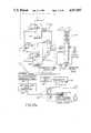
- FIG. 1is a system-type diagram of the ultrasonic imaging device of the invention, illustrating the use of the device to image a coronary artery during a PTCA procedure;
- FIG. 2is an enlarged and partially sectioned view of a portion of the coronary artery in FIG. 1, showing the probe assembly of the ultrasonic imaging device of the invention located at the tip of the catheter approaching an area of plaque buildup in the artery and the equivalent histologic view of the same to a surgeon;
- FIG. 3is the same view as illustrated in FIG. 2, except the catheter has been further drawn into the area of plaque buildup in the coronary artery so as to bring a balloon section of the catheter into the area, where the balloon is inflated in order to compress the plaque in accordance with a standard PTCA procedure;
- FIG. 4is the same view as illustrated in FIGS. 2 and 3, except the catheter has been repositioned so that the probe assembly of the ultrasonic imaging device is in the area of the plaque buildup, and it is providing the surgeon with an image of the cross-sectional area of the coronary artery that can be used to determine how well the PTCA procedure opened the artery for additional blood flow;
- FIG. 5is a cross-sectional view of the tip of the catheter in FIGS. 2-5, illustrating the probe assembly of the ultrasonic imaging device of the invention housed in the tip of the catheter and adjacent to its balloon section;
- FIG. 6is perspective view of the probe assembly of FIGS. 2-5 with the sheath and epoxy encapsulation covering the probe assembly removed to expose the underlying electronics and associated construction;
- FIG. 7is cross-sectional view of the probe assembly taken along the line 7--7 in FIG. 6;
- FIG. 8is a side view of the probe assembly with a portion cut away to expose the composition of the body of the assembly along its longitudinal axis;
- FIG. 9is a graph illustrating an exemplary frequency spectrum echo response for one of the transducer elements defined by a conductive trace on the probe assembly and an overlying portion of a band of a piezoelectric polymer, where the abscissa is the frequency of the acoustic waves impinging on the transducer element measured in Megahertz and the ordinate is the electrical response of the piezoelectric polymer measured in microamps;
- FIG. 10is a graph similar to that of FIG. 9, except the frequency response of the transducer element is measured after it has been converted by a transimpedance amplifier configuration incorporated in integrated circuitry on-board the probe assembly, where the abscissa is still measured in megahertz but the ordinate is now measured in volts;
- FIG. 11is a schematic block diagram of the electronic circuitry contained in each of the plurality of chips mounted to a carrier portion of the probe assembly;
- FIG. 12is a detailed component diagram of a delay buffer which provides important timing signals in the electronic circuitry of FIG. 11;
- FIGS. 13a and 13billustrate a schematic block diagram of the in vitro processing and imaging unit of the ultrasonic imaging device according to an exemplary embodiment of the invention
- FIG. 14is a diagrammatic representation of a portion of the array of acoustic transducers and one of a plurality of radial focus beams, each having a plurality of focus points for reconstructing an image derived from partial vectors associated with the ultrasonic signals received by the transducers;
- FIG. 15is a schematic illustration of the screen of a video display used to generate the images shown in FIGS. 2 and 4, showing how the plurality of radial focus beams are mapped onto the pixels of the screen;
- FIG. 16is an enlarged and partial view of the schematic in FIG. 15, illustrating how the points comprising the focus beams are matched with the pixels of the video display screen;
- FIG. 17is a graph in Cartesian coordinates of an exemplary beam profile for each element in the transducer array, where the normalized amplitude as plotted on the ordinate is measured at a constant radius and the beam angle plotted on the abscissa is measured from the center of the cylinder formed by the array;
- FIG. 18is a graph in Cartesian coordinates of the Hamming window profile for a single element in the transducer array, where the normalized amplitude is plotted on the ordinate and a circumferential distance from a central radial beam is plotted on the abscissa.
- an alternative applicationis the use of the invention on the end of a catheter without the incorporation of a balloon.
- a specific example of such a useis a pharmaceutically therapeutic use where cholesterol-inhibiting drugs are used for regional therapy and the imaging device of the invention is used to monitor the effectiveness of the drugs in removing plaque.
- Another specific example of an alternative useis a physical therapeutic use such as measuring blood flow rates (using Dopler sound imaging in conjunction with invention) or determining sizes and locations of gall stones and the like.
- Yet another example of an alternative applicationis the incorporation of the invention into a catheter in conjunction with a laser or like devices for burning plaque in the arteries.
- a buildup of fatty material or plaque 12 in a coronary artery 14 of a heart 16may be treated in certain situations by inserting a balloon 18, in a deflated state, into the artery via a catheter assembly 20.
- the catheter assembly 20is a three-part assembly, having a guide wire 19, a guide catheter 20a for threading through the large arteries such as the aorta 22 and a smaller diameter catheter 20b that fits inside the guide catheter.
- the smaller catheter 20bis inserted.
- the guide wireis first extended into the artery, followed by catheter 20b, which includes the balloon 18 at its tip.
- an ultrasonic imaging deviceincluding a probe assembly 24 housed in the tip of the catheter 20b provides a surgeon with a cross-sectional view of the artery on a video display 26.
- Signals from the probe assembly 24, indicative of reflected ultrasonic waves,are transferred along a cable 28 to a signal processor 30 located outside the patient.
- the catheter 20bends in a three-port junction 29 of conventional construction that couples the catheter to an inflation source 31, a guide wire source and the signal processor 30.
- the inflation and guide wire ports 29a and 29b, respectively,are of conventional PTCA catheter construction.
- the third port 29cprovides a path for the cable 28 to connect with the signal processor 30 and video display 26 via an electronic connector 33.
- the inventionis not intended to be limited to a PTCA environment.
- the port 29amay be an injection site for the drug instead of an inflation source and, of course, the balloon 18 at the end of the catheter 20b is not needed.
- the imaging deviceprovides an image 32 on the display 26 that indicates when the balloon 18 is within a partially blocked area of the coronary artery 14 as is best seen in FIGS. 2-4.
- the tip of the catheter 20a containing the probe assembly 24is moved past the blocked area in order to bring the following balloon 18 into the area as shown in FIG. 3.
- the balloon 18is thereafter inflated so as to compress the plaque 12 causing the blockage.
- the cardiologistmay check the results of the PTCA procedure, by slightly withdrawing the catheter 20a in order to bring the tip and the associated probe assembly 24 back into the blocked area as shown in FIG. 4. If the PTCA procedure was successful, the image 32 on the video display screen 26 will show the lumen of the artery 14 has increased in cross-sectional area.
- the probe assembly 24is constructed to be sufficiently small to fit in cavities of approximately the size of a human coronary artery as shown in the illustrated embodiment.
- a polymer piezoelectric materialis used to provide transducer elements for generating and receiving ultrasonic acoustical waves.
- the polymer piezoelectric materialis continuous in order to provide for ease of manufacture.
- the piezoelectric materialforms a ring 44 for viewing in a plane P (FIG. 5) passing through the material and normal to its surface; however, it will be appreciated that in other applications or for viewing in alternative planes, the piezoelectric material may take other forms.
- the natural frequency of the materialit is necessary that the natural frequency of the material be much higher than the chosen operating frequency. In the illustrated embodiment, a frequency of 20MHz is chosen as the operating frequency.
- piezoelectric polymersare suitable for use as the ring 44.
- An acceptable materialmust have the following characteristics. The material must, of course, have good sensitivity characteristics for detecting reflected ultrasonic waves. Because of the small size and cylindrical shape of the ring 44, however, the piezoelectric material must also be capable of being formed into a suitable shape of very small diameter (e.g., a cylinder of about 1.5mm. diameter). For example, the material may start as a flexible sheet or, if it is not flexible, it may be formed directly into the desired shaped by deposition or other well-known forming processes. Also, because the material is continuous, it must be characterized by good acoustic behavior.
- the inventionincludes electronics that aid in eliminating shear waves or ringing.
- the piezoelectric materialmust be well matched to the human tissue immediately surrounding the probe assembly 24.
- the copolymer P(VDF-T r FE)having a thickness of approximately nine (9) microns.
- PVDFpolyvinyl styrene
- copolymer P(VDF-TFE)having a thickness of approximately nine (9) microns.
- PZTpolymers and ceramics
- a depositable materialsuch as ZnO.
- a continuous ring 44 of materialis much more preferable than an individual piece of piezoelectric material for each transducer element.
- the manufacturing complexities avoided and the cost savings obtainedare considerable if a continuous ring of piezoelectric material is used. For example, using a continuous material, there is no need to cut individual elements. Cutting individual elements of the very small size required for the probe body 42 would be very difficult and expensive.
- the piezoelectric polymer material comprising ring 44must be supported, and the body 42 serves the purpose. Since acoustic energy is reflected at interfaces between regions of differing acoustic impedance, a hard backing for the transducer array is necessary to ensure that most of the ultrasonic energy is not absorbed by the backing.
- an alumina compositioni.e., Al 2 O 3 ) of the body 42 provides the necessary hard backing.
- the body 42 of the probe assembly 24has box-shaped and cylindrically-shaped sections 42a, 42b, respectively.
- a third transitional section 42cjoins the other two sections 42a, 42b by tapering the body 42 along its axial length from the cylindrical section to the box-shaped section.
- the probe assembly 24is sufficiently small to fit inside areas such as the coronary artery 14, it preferably has the following approximate dimensions: Diameter of cylindrical section 42b--1.5 millimeters; width of one side of box-shaped section 42a--3/4 millimeter; axial length--3.0 millimeters; diameter of axial bore 40 --1/2 millimeter.
- the body 42is formed by known injection molding techniques. Because the dimensions of the body 42 are small and the tolerances are small (e.g., the tolerance on the outer diameter of the cylindrically-shaped section 42b is 500 microinches), very precise machining is required for the injection mold. Furthermore, the small size of the body 42 makes it impractical to polish after molding. Therefore, it is important that the injection molding process provides a smooth surface.
- the body 42 of the probe assemblynot interfere with conventional PTCA, regional drug therapy and other therapeutic or diagnostic procedures that utilize catheters and may advantageously incorporate the invention in order to improve those procedures. Therefore, in order to secure the probe assembly 24 to the tip of the catheter 20b, a conventional guide wire lumen inside the catheter is telescopically fitted over a mating guide wire lumen 38 forming the central bore 40 in the probe assembly as best seen in FIG. 5. To further secure the probe assembly 24, the end of the catheter 20b is joined to the probe assembly by way of an epoxy material 41 encapsulating and protecting the integrated circuits 54 mounted on the rectangular section of the body.
- the ability of the catheter 20b to perform a conventional catheterization procedureis uneffected, since the bore 40 allows the guide wire to exit the tip of the probe assembly 24.
- the bore 40is lined with, for example, kapton.
- the outside of the probe assembly 24is covered by a protective sheath (not shown) made of, for example, parylene.
- the catheter 20bsupports the balloon 18 at its one end.
- the balloon 18is positioned adjacent the probe assembly 24 and is isolated from ambient conditions by sealing the two ends of the balloon to the catheter in a conventional manner.
- the area of the catheter 20b covered by the balloon 18includes a series of holes 43 for communicating fluid between the balloon and an inflation source 31 in FIG. 1.
- Each wire in the cable 28is formed of conventional "magnet" wire--i.e., a solid conductor protected by an insulating coating.
- a ribbon of copper(not shown) is spiraled in order to provide a ground shield for the signals carried by the cable 28.
- the copper ribbonis provided with a protective insulating coating.
- a plurality of underlying conductive traces 46are formed on the surface of the cylindrical section 42b of the body 42 and underlie the ring 44 of continuous piezoelectric material.
- the outer surface of the ring 44 of piezoelectric materialhas a thin coating of metallic material.
- Each element of the arrayis defined by an area of the ring 44 overlapping the conductive traces as generally indicated in FIG. 7.
- a film of an epoxy glueholds the inner surface of the ring of material to the surface of the probe body 24.
- the ring 44may be formed of the piezoelectric material as a cylinder or it may be a flat sheet that is rolled and joined at a seam. Preferably, the ring 44 is a seamless cylinder.
- the conductive traces 46are evenly spaced about the circumference of section 42c of the body 42. Such a construction results in the elements of the array being aligned with their length axes parallel to the length axis of the body 42. Preferably, there are 64 conductive traces 46 and, therefore, 64 transducer elements.
- the body 42is first coated with a well-known titanium and tungsten mixture, using conventional deposition techniques. Over the titanium and tungsten mixture, a layer of gold is deposited onto the body 42. To etch the conductive pattern, the body 42 is held in a jig (not shown) and state-of-the-art laser oblation methods are used to etch the pattern on each side of the box-shaped section 42a, proceeding one side at a time. For the cylindrically-shaped and transitional sections 42b and 42c, respectively, each is etched separately by incrementally rotating the body in the jig.
- the body 42In addition to not absorbing significant amounts of ultrasonic energy, the body 42 must not have resonant effects due to the energy reverberating in the cylindrically-shaped section 42b that are within the frequency region of operation. Such reverberation is evidenced by a notch in the frequency response of each element in the array. The frequency position of the notch is controlled by keeping the alumina under the transducer thin.
- the cylindrical section 42b of the probe body 42is recessed so that the body defines a thin annular wall 48 for supporting the ring 44 of piezoelectric material.
- the frequency response spectrum of the ring 44 of piezoelectric materialincludes a notch N whose frequency position in the spectrum is effected by the following factors: (1) the thickness of the wall 48, and (2) the acoustic velocity of the sound within the material comprising the wall.
- the notch Nis positioned outside the frequency region of the transducer array (e.g., 15-25MHz).
- the annular wall 48has a thickness d as illustrated in FIG. 8 and destructive interference forming the notch N in FIG. 9 occurs when the half-wavelength ⁇ /2 of the ultrasonic waves is approximately equal to the thickness d.
- nis an odd integer--i.e., 1, 3, 5, etc.
- the first notch(N in FIG. 9) should be at no lower a frequency than, for example, 28MHz. Knowing the velocity V of the ultrasound waves through the alumina, equation (1) can be rewritten as ##EQU2## where f is the frequency of the ultrasound waves. Substituting the values for equation (3) gives ##EQU3## Therefore, the thickness of the annular wall 48 should be 0.182 mm or less. In order to fill the recess 50 formed by the annular wall 48 without significantly effecting the acoustic properties of the probe body, an acoustic backing material 52 such as urethane is used.
- small piezoelectric transducers made from copolymers such as P(VDF-T r FE)are characterized by very high electrical impedance values (e.g., 30K ohms for one element), very low current signal levels are generated by each array element in response to reflected acoustic waves.
- transimpedance amplifiersare located on-board the probe assembly 24 and in close physical proximity to the ring 44 of piezoelectric material.
- the amplifiersprovide current-to-voltage amplification in a linear relationship where one microamp produces approximately 750 microvolts.
- the probe assembly 24includes a plurality of the integrated circuit chips 54 (four in the preferred embodiment).
- Each chip 54includes current amplifiers as discussed in greater detail in connection with FIG. 11 that receive low current signals from the high impedance transducer elements and provide the low impedance (e.g., 50 ohms) cable 28 with a high voltage signal.
- the actual amplifier devices for each channelare current amplifiers with an approximate gain of 15 from transducer element to cable, the overall effect of the amplifiers is one of transimpedance since the signal is received from a high impedance current source (the element) and delivered to a low impedance load as a voltage (the cable and its termination).
- FIG. 10illustrates the frequency response of an element in the transducer array with the transimpedance amplifier and additional voltage amplification.
- the four integrated circuit chips 54are of an inverted chip design and are bonded to conductive pads 56 formed on the box-shaped section 42a of the probe body.
- the pads 56interconnect each of the four chips 54 and also provide a connection between the chips and the cable 28 within the catheter 20a that connects the chips to the signal processor 30 outside of the patient.
- the stripsextend along the axial length of the probe 24, beyond the ring 44 of piezoelectric material and down the transitional section 42c to conductors 58 on the underside of the chips 54.
- the cable 28 from the signal processor 30provides communication channels between the processor and the integrated circuits 54, using a minimum number of wires.
- the four integrated circuit chips 54provide a multiplexing function that distributes excitation pulses from the signal processor 30 to a predetermined one or ones of the transducer elements.
- a single pair of wires T+, T- in the cablecarry the excitation signals as differential pulses in series format from the signal processor 30 to the chips 54.
- each excitation signalis routed to an appropriate one of the transducer elements in order to execute an excitation sequence used by the preferred image reconstruction technique.
- Each chip 54 as illustrated in FIG. 11has 16 channels 60 associated with 16 of the 64 transducer elements XD 1 -XD 64 defined by the ring 44 of piezoelectric material and the conductive traces 46. Each chip 54 is responsible for sequentially transmitting and receiving ultrasonic signals on one of its associated 16 channels. At any given time, exactly one of the chips 54 will be designated as active, where "active" indicates the one chip 54 that is currently exciting one of its associated transducer elements XD N . Furthermore, at any given time only one of the 16 channels 60 on an active chip 54 is free to be excited by an excitation signal or to receive reflections or echos. The electrical signals generated from the reflections impinging on the free transducer element are amplified and sent via the transmission cable line 28, to the externally located signal processor 30 as explained more fully hereinafter.
- Each excitation signal intended for one of the transducer elements XD Ntravels down the transmission lines T+, T- as a differential pulse.
- the excitation signalconsists of two closely spaced short duration (of approximately 25 nanoseconds) pulses.
- An excitation signal of this formgenerally provides significantly more transmitted acoustic energy from an excited transducer than would a single pulse.
- an optimizationis realized between maximizing the transmitted acoustic amplitude and maintaining reasonable image resolution.
- the particular form of this signalcan be modified to maximize the desired features of the signal.
- this differential pulseis received and amplified by the differential pulse receiver amplifier 62 as shown in FIG. 11.
- the differential pulseis supplied to the T+ and T- transmission cable lines 28 via an analog buffer (not shown) which converts a received unipolar excitation signal from the signal processor 30 into the desired differential pulse.
- only one of the chips 54receives timing signals on lines CDATA and CCLK and an excitation signal on line T+,T- from the transmission cable 28, although all four of the chips are capable of receiving these signals because of their identical structure.
- This one chip 54 receiving timing and excitation signalscooperates with the other three chips in a master-slave relationship where the signal lines CDATA, CCLK and T+,T- are used to generate a system clock (i.e., SYS CLK) for synchronizing all four chips 54, and to distribute the excitation signal T+,T- by way of line SYSTRAN .
- SYS CLKsystem clock
- bus linesare common to all the chips and are connected between adjacent chips by extensions 56a of conductive pads 56, which are formed around the box-shaped section 42a of the body 42 (FIGS. 6 and 8).
- the buscomprises lines I REF , SYSTRAN, ANA OUT, SYS CLK, V+ and V-.
- the schematic diagram of one of the chips in FIG. 11will be treated as the master chip which receives the signal lines CDATA, CCLK, T+,T- and V+, V- from the transmission cable 28.
- the SYSTRAN linedelivers the excitation signals to all the chips 54, and as will be described in more detail later, other signals are used to control the application of the excitation signals to the 64 transducer elements XD 1 -XD 64 .
- FIG. 11shows 16 elements on one of four chips for a total of 64.
- a receiver amplifier 62 on the chip 54receives the excitation signal in its differential pulse form and converts it to a unipolar form. From the receiver amplifier 62, the excitation signal is passed through an inverting buffer 64 which supplies an inverted version of the excitation signal to all the chips through the common SYSTRAN line.
- the master chip 54responds to external bias currents on lines T+, T- by generating a cable bias current I CABLE BIAS which is used as a bias reference signal for indicating which chip 54 is the master chip receiving the timing and excitation signals.
- the reference current I REFis generated and distributed to all the chips 54 for producing the necessary bias voltages on the other chips. Specifically, the current I REF is generated at the drain of MOSFET 66 in the transistor current mirror 64, 66 on the master chip 54.
- the reference current I REFis used by bias generators 70, 72 to produce bias voltages for a delay buffer 74 and the individual channel amplifiers 60b which are discussed more fully hereinafter.
- the cable bias current I CABLE BIASis generated by a current mirror transistor configuration comprising two p-channel MOSFET transistors 64, 66 with their gates connected in common, and their sources connected to a positive supply voltage V+, as shown in FIG. 11.
- the gate of one MOSFET transistoris also connected to its drain which in turn is connected to the T+ and T- lines of cable 28.
- the voltage of the T+ and T- transmission cable lines of the master chip 54are held at a voltage lower than the positive supply voltage V+, and as a result of this lower voltage, the cable bias current I CABLE BIAS flows from the common gate and drain connection of the transistor 64 located on the master chip 54.
- the cable bias current I CABLE BIASis utilized to assert a "M" line on the master chip 54.
- the other chips 54will have no cable bias current flowing, due to the absence of the T+ and T- transmission cable connections, and will have a negated "M” line.
- a comparator 68is used to compare the voltage level of the cable bias current on the line I CABLE BIAS to a predetermined comparator reference voltage V R1 derived from series resistors R 1 and R 2 .
- the line for a cable bias current I CABLE BIASremains at the supply voltage V+ which is greater than the reference voltage V R1 , thereby causing the comparator 68 to negate the "M" line which designates the chip as a slave chip. Otherwise, if the T+ and T- transmission lines of the cable 28 are connected, there will be a voltage drop on the I CABLE BIAS line. This reduced voltage level will be lower in magnitude than the comparator reference voltage V R1 , thereby causing the comparator 68 to activate the "M" line which designates the chip as the master chip.
- Timing signals received by the CDATA and CCLK linesare also dependent upon reference voltages generated by the current I REF or I CURRENT BIAS.
- the signal on the CDATA lineis input to an amplifier 76 along with a reference voltage V R2 generated at the node connecting resistors R 3 and R 4 from the I CABLE BIAS circuitry.
- This input amplifier 76insures the proper voltage levels on the chip 54.
- the output of this input amplifier 76is sent to an inverting buffer 78 that acts as a transmission gate which is controlled by the state of the "M" line.
- the CCLK transmission line from cable 28it is connected through an input amplifier 80 along with the aforementioned reference voltage V R2 .
- the output of amplifier 80is sent to a non-inverting transmission gate buffer 82, which in turn produces the clock signal SYS CLK on the common bus line for distribution to all the chips 54.
- This clock signal SYS CLKis used to sequence the shift register 84 on each chip 54 in order to sequentially activate the 64 channels 60 on the probe assembly 24 as explained more fully hereinafter.
- the sequential stepping through the 16 channels 60 on each of the chips 54is accomplished by shifting a single logic bit through the 16 bit shift register 84.
- the logic outputs of the shift register 84 of an inactive chip 54are all negated. Therefore, at any given time exactly one of the 16 outputs of the shift register 84 on one of the chips 54 is "active" and all the other 63 outputs are disabled.
- the CLK input to the shift register 84driven by the SYS CLK bus line, allows the logic bit to be sequenced from one output Q N to the next Q N+1 .
- Each of the output lines Q N of the shift register 84is used to sequentially and individually enable the transducer channels 60 on the chip 54 by way of a NAND gate 60a and an enable input to the corresponding channel amplifier 60b. As indicated in FIG. 11, there is a one-to-one correspondence between the individual outputs Q N of the shift register 84 and the individual transducer channels 60. For example, output Q 1 is associated with channel 1, output Q 2 is associated with channel 2, etc.
- a separate chip select signal CSis asserted by the one of the four chips 54 that is currently activating one of its channels 60 for the generation and detection of ultrasonic acoustic signals. At this time, chip select lines CS of the other three chips 54 are negated.
- the CS signalis asserted by using one clocked SR flip-flop 88 and one unclocked SR flip-flop 90 as explained more fully hereinafter.
- the first bias generator 70receives as an input the common reference current I REF which is generated on the master chip 54, and utilizes this signal to produce the desired bias voltage on a BUF BIAS line for the delay buffer 74. Since the presence of a bias voltage on the BUF BIAS line is only needed for a particular chip 54 when one of its channels 60 is active, the CS (inverted chip select) line is used to selectively activate and de-activate the bias generator 70.
- the second bias generator 72is used to provide the proper bias voltage on a AMP BIAS line for the transducer channel amplifiers 60b.
- the second bias generator 72is selectively activated and de-activated by the logical ORing of the CHIP TRANS line (an inverted SYSTRAN line) and a WAIT line from the delay buffer 74 at OR gate 73.
- the amplifieris activated only after a channel 60 has generated ultrasonic acoustic waves.
- the bias voltage AMP BIAS lineis supplied to the amplifiers by the second bias generator 72 after the associated transducer element XD N has been excited to generate ultrasonic acoustic waves.
- the delay buffer 74serves an important timing role in the operation of the chips 54.
- a particular embodiment of the delay buffer 74is illustrated in FIG. 12. It will be appreciated, however, that many alternative designs may also provide the desired timing signals of WAIT and BUF RESET.
- the delay buffer 74uses the excitation signal on the CHIP TRANS line as its input along with the bias voltage BUF BIAS from the first bias generator 70, the delay buffer 74 produces three important output signals. Specifically, upon receiving an excitation signal on the CHIP TRANS line (via the lines T+ and T- of the transmission cable 28), the delay buffer 74 sets the WAIT output line active, thereby disabling the second bias generator 72 from producing a bias voltage AMP BIAS for the channel amplifiers 60b of the channels 60. After sufficient time has passed to ensure the WAIT line is high and the channel amplifiers 60b are deactivated (a delay is provided by the inverters 101 in FIG.
- the delay buffer 74sends the excitation signal on the BUF TRANS bus line, thereby sending the excitation signal to all of the transducer channels 60.
- the BUF TRANS lineis NANDed with one of the Q N outputs of shift register 84 by the NAND gate 60a and buffer FET 60e. Because only one NAND gate 60a in the channels 60 of chip 54 has both inputs active, only one of the transducer element XD 1 -XD 16 is excited.
- the beam pattern formed by the excitation of an elementis optimized during both transmission and reception of ultrasonic waves by providing low impedance paths through elements adjacent the excited element.
- the low impedance characteristic of adjacent elementsminimizes the aperture width, thereby creating a beam of maximum width.
- the widest beamis most desirable since it provides the greatest overlap with adjacent beams and hence the most information during reconstruction of an image.
- each channel 60includes a MOSFET 60d controlled at its gate by a Q n signal (i.e., Q n from shift register 84 inverted by inverter 60f).
- an active Qn signalcauses the node of the transducer element (i.e., the conductive trace 46) to be effectively grounded, thereby shunting the high impedance transducer element.
- the node for the transducer elementremains grounded and the element shunted until the associated Qn line from the shift register 84 becomes active.
- Qn activethe FET 60d is turned off and the transducer node is released from a ground potential so that it may deliver an excitation signal to the transducer element XD N .
- the BUF RESET lineis briefly asserted by the delay buffer 74 in order to clamp the MOSFET transistors 60c to ground such that the excited transducer element is effectively shunted in order to sweep off any charge at the node of the excited element (to rapidly return the amplifier 60b to its quiescent bias state) and quell any transient signals or "ringing" at the input to the amplifier 60b.
- the signal on the BUF RESET lineresumes its normally negated state until the next transmission cycle, thereby freeing the just excited transducer element to respond to reflected ultrasonic acoustic waves.
- the delay buffer 74negates the WAIT line which in turn asserts the AMP BIAS line from the second bias generator 72, thereby turning on the channel amplifiers 60b.
- the AMP BIAS lineactive, the one of the channel amplifiers 60b (as determined by the Q N outputs of shift register 84) amplifies the current signal received from the associated transducer element XD N and delivers a current signal at the AMPOUT line.
- an asynchronous RESET signalis generated by strobing the T+,T- and CCLK lines so as to bring the SYSTRAN and SYS CLK bus lines both to logic states necessary to produce an asserted RESET signal by logic gate 92.
- This asserted RESET signalis input to the S input of the unclocked SR flip-flop 88. It also clears the 16-bit shift register 84 and presets the clocked SR flip-flop 90. In response to this RESET signal, the unclocked SR flip-flop 90 output is asserted as well as the clocked SR flip-flop output 88.
- a negated CS chip select signalis produced from an OR gate 94. Note that all chips are inactive during the reset. After the chips 54 have been reset and normal chip operation is desired, both the SYSTRAN and the SYS CLK lines are brought back to their quiescent active state.
- the first transducer channel 60 on the master chipis activated. This is accomplished by loading a data bit into the shift register 84 on the master chip 54 by asserting the CDATA line followed by one clock pulse.
- the "DSR IN" line from the Q 16 of the shift register 88 on the previous chip 54is asserted (if the presently active chip is a slave) and ANDed with the "M” line (inverted “M” signal) at AND gate 102 to produce a signal which is ORed with the CDATA signal at OR gate 104.
- the resulting signalis shifted into the DIN input of the shift register 84 of the master chip in response to clock pulse on the SYS CLK line.
- the process of transmitting and receiving sequentially through all the transducer channels 60 on the devicebegins.
- the data bit from CDATAis shifted through the Q N outputs of the shift registers 84 of the four chips 54, it sequentially activates the 64 channels 60 and their associated transducer elements XD 1 -XD 64 of which "Qn" denotes which transducer channel 60 is active.
- channel 1 of the master chip 54is made active in response to the presence of the data bit on the Q 1 line of the 16-bit shift register 84.
- An excitation signal in a differential pulse formatis then sent to the master chip 54 via the T+ and T- transmission lines of cable 28. As previously discussed, this signal is then converted to the SYSTRAN signal by way of amplifier 62 and inverting buffer 98.
- the SYSTRAN signalis inverted at the input to AND gate 100.
- the other input to the AND gate 100is an inverted chip select signal CS . Since the CS signal for the master chip 54 is currently asserted, the excitation signal passes through the AND gate 100 and into the delay buffer 74. As previously explained, the delay buffer 74 sends the excitation signal on the BUF TRANS line to the transducer channels 60.
- the transimpedance amplifiers included in each chip 54are implemented by series connected current amplifiers 60b and 86.
- Each of the amplifiers 60b and the amplifier 86has a nominal gain of approximately five for the amplifiers 60b and three for the amplifiers 86.
- Ultrasonic acoustic signals generated by a transducer element XD Nare reflected as they propagate through the coronary artery and into the surrounding tissue. These reflected acoustic waves impinge on the transducer element XD N , and are converted to electrical signals amplified by the channel amplifier 60b before being sent to the AMP OUT bus line as previously explained.
- the signals indicative of the reflected ultrasonic wavesare delivered to the amplifier 86, thereby multiplying the AMP OUT bus current to a level acceptable for transmitting on the analog output line ANA OUT of the transmission cable 28 for transmitting the signals to the external signal processing stage 30.
- the signals on the ANA OUT linerepresent the relative amplitudes of the reflected ultrasonic waves and accordingly contain important timing information about the path length of the reflected ultrasonic waves and the density of the reflecting medium.
- the master chipis deactivated and the next of the three slave chips is activated. This is accomplished through the connection of the Q 16 output of the shift register 84 to DSR OUT which is connected to the DSR IN input line of the next chip by means of the traces 56a around the body 42.
- the data bit at Q 16is shifted into Q 1 of the shift register 84 in the neighboring chip 54 upon the cycling of the CCLK line.
- the input line to the next chip (DSR IN)is ANDed with the "M" line at AND gate 102 which is then ORed with the CDATA line at OR gate 104 and input to the 16-bit shift register 84.
- the "M" linewill be asserted which allows the passage of the data bit on the DSR IN line from the Q 16 line of the previous chip to the input DIN line of the data shift register 84 of the next chip.
- the master chip 54is deactivated (i.e., its chip select CS is negated) and the next chip is activated (i.e., its chip select CS is asserted).
- the previous chipis deactivated due to the connection of the Q 16 output of the shift register 84 to the S input of the clocked flip-flop 88, thereby negating the CS signal.
- the next chip 54is activated as a result of the SYS CLK cycling and resetting both RS flip-flops 88, 90 which asserts the chip select line CS. Since the signal at the DIN line (which is in effect the Q 16 output from the previous chip) is also connected to the R input of the clocked flip-flop 88, an asserted CS signal results which designates this next chip 54 as active.
- the transmitting and receiving processis done in sequence for each of the 16 transducer channels 60 on this chip in the same manner previously described for the master chip. After this process is completed, this chip 54 will be deactivated and the next chip (second slave) will be activated in the same manner as previously described. The same process continues until all 64 transducer elements XD N have been excited. After all the transducer elements XD N of the last chip 54 have been sequenced through for transmitting and receiving, another data bit is sent via the transmission cable 28 to the CDATA line of the master chip 54 to begin the entire process again, starting from the first transducer channel 60 on the master chip.
- the chips 54 located on the probe assemblyuse the excitation and control signals supplied via the transmission cable 28 to sequentially generate and detect ultrasonic acoustic waves from individual transducer elements XD N .
- the detected reflections of ultrasonic wavesare first converted to electrical signals, amplified and then sent via a transmission line in cable 28 to the external signal processing stage 30.
- the signals sent to the external signal processing stage 30contain important amplitude and timing information which is essential to reconstruct images of the cavity in which the probe assembly 24 is operated.
- only one of the several chips 54is active at any given time, and only one of the transducer elements XD N associated with the active chip is transmitting and receiving.
- the chipis deactivated and the next chip is activated. This sequencing of the transducer elements XD N continues on each of the next chips 54, and then is repeated continuously in order to provide real-time signals for the external signal processing stage 30 to produce images.
- a first channel 60may transmit ultrasonic waves in response to the excitation signal and a second channel may be made available to receive the reflected ultrasonic waves. Also, it may prove desirable to transmit or receive on more than one channel 60. Because these alternatives involve changes to the illustrated embodiment of chip 54 that will be readily discernable to those skilled in the art, such changes are not discussed in detail herein.
- ultrasonic signalsare received by the processing system from the probe assembly via the line ANA OUT of the transmission cable 28.
- the received signalsare amplified at a receiving amplifier and then passed to an analog-to-digital (A/D) converter.
- A/Danalog-to-digital
- each transducer channel 60is controlled by the signal controller 30 to transmit and receive ultrasonic signals a plurality of times (e.g., 100 times) before the active shift register 84 sequences the associated chip 54 to the next channel. Because the probe assembly 24 is intended for imaging in very small areas such as a coronary artery, the two-way path of a generated and reflected signal is short (e.g., eight millimeters) and as a result of this short path the time delay for receiving a reflected signal is also very short (e.g., five to ten microseconds).
- each transducer element XD Nmay be excited multiple times, and the reflected signals are averaged to provide an increased dynamic range. Because the response characteristics of each transducer XD N can be improved by exciting it a number of successive times while maintaining an apparent real-time image of the display screen 26, the inherent poor sensitivity of the piezoelectric polymer chosen for the transducer material is overcome.
- a plurality of differential pulsed excitation signalsare transmitted on the T+ and T- transmission lines of cable 28 while keeping active the same transducer channel 60 (i.e., without sequencing shift register 84).
- sufficient timeis allowed for detecting reflected ultrasonic signals and delivering them to the ANA OUT line.
- the reflected ultrasonic signalsare detected, they are signal averaged at a dynamic signal averager in order to produce a single collective signal with a considerably higher dynamic range than any of the individually received signals.
- a pulseis sent from the signal processor 30 on the CCLK transmission line of cable 28, thereby producing a digital pulse on the CLK line of the chip 54 which is input to the 16-bit shift register 84.
- This CLK pulsecauses the shift register 84 to shift the single logic 1 value to the next output line, thereby deactivating the previous transducer channel 60 and activating the next transducer channel where the foregoing process is repeated.
- the digitized and averaged signal representing the detected acoustic reflection or echois collected, it is stored for a brief amount of time in an acoustic frame buffer which is essentially a high-speed memory system.
- a cross-point switch responsive to a focus map memory and a sequenceruses selective pieces of data from the acoustic frame buffer and combines this data with weighting factors W 0 -W 9 at multiplier elements.
- the resulting weighted signalsare then input to a summer which performs a summation of all the weighted inputs.
- a single data streamis then output from the summer to a digital rectifier and low pass filter. Depending on its proximity to a pixel when mapped onto a cartesian coordinate system (linked to the video display as explained hereinafter), this single data stream may be used to provide gray scale information for the pixel location on the screen of the video display 26.
- the reconstructed, rectified and filtered vector datais subjected to a two-pass process.
- the first passsamples each vector signal to the nearest vertical (Y) coordinate in a cartesian grid, according to the angle of the beam reconstruction as indicated by the placement of the vector signals on vertical grid lines in FIG. 15.
- the second passre-samples the resulting signal into the nearest horizontal (X) coordinate in the cartesian grid as indicated by the arrows in FIG. 15.
- This scan conversion processis accomplished by first passing each vector output from the digital filter through an angle-dependent sample rate converter and storing the results in a Y, ⁇ buffer.
- the concentric squares generator 128takes the Y, ⁇ converted data and fits it to the nearest point in the cartesian pixel matrix of a video system.
- a video systemprovides a memory interface between the concentric squares generator and the pixel memory.
- the video systemalso provides dynamic pixel memory refresh and video timing and sync signals for the video monitor 26.
- the pixel informationis passed through a gamma correction lookup table of well-known design and then to a digital-to-analog converter before it is displayed on the video monitor 26.
- the receiver 106functions to relay the signals from the probe assembly 24 to the A/D converter 108.
- the receiverprovides full scale voltage amplification of the signals from the probe assembly 24 to the A/D converter 108.
- the receiver 106provides impedance matching to the A/D conversion system 108.
- the analog-to-digital (A/D) converter 108takes the signal and converts it into 8-bit two's complement values at a frequency of 400 MHz.
- the center frequency of the ultrasonic signals being transmitted and received by the probe assembly 24is about 20 MHz.
- the corresponding bandwidth for these signalsis about 10 MHz, thereby placing the lower frequency at about 15 MHz and the upper frequency at about 25 MHz. From empirical study, it is found that the sampling rate should be sixteen times the maximum frequency or about 400 MHz. Using this sampling rate for the A/D conversion process allows for image reconstruction which is sufficient to produce very clear images with good resolution.
- the digital valuesafter the digital values have been produced by the A/D converter 108, they are input to a dynamic signal averager 110 which takes a number of these input 8-bit values and produces a collective 16-bit value.
- the dynamic signal averager 110operates to add a number J of the input 8-bit digital values together to produce the resulting 16-bit digital value, and as such the maximum number of 8-bit values which can be added together to produce one 16-bit value without an overflow occurring is 256. Therefore, the maximum acceptable number for J is 256.
- the dynamic range of the resulting 16-bit valueis increased by 3dB each time the total number of summations equals successive powers of two (e.g., 2, 4, 8, 16, etc.) Accordingly, at the maximum number of summations (J equal to 256), the dynamic range is effectively increased by 24dB.
- the number of times each of the input signals is summed in the signal averager 110is predetermined and corresponds exactly to the number of excitation signals sent to each individual transducer element XD N of the probe assembly 24. For example, in the preferred embodiment 100 individual excitation signals are sent to a particular transducer element XD N , and 100 individual receive signals are generated, each providing information relating to the small cavity. If these excitation signals are sent very close together in time, the corresponding received signals will provide information relating to the cavity during such a short time interval that the information may be considered for the practical purposes of a real-time display as having been simultaneously gathered.
- the averaging processserves to increase the dynamic range by cancelling any random component of the signals received or generated by the transducer and analog amplification stages of the receiver 106. Therefore, only the stationary parts of the signals are enhanced, thereby producing signals which relate to the particular configuration of the small cavity.
- the dynamic signal averager 110is of a conventional design that provides for the high speed transfer of the collected data to the acoustic frame buffer 112.
- the dynamic signal averager 110may be realized using an arithmetic logic unit (ALU) operating in conjunction with a 16-bit memory buffer.
- ALUarithmetic logic unit
- the ALUreads one 8-bit word from the A/D converter 108, adds this 8-bit value to the 16-bit buffer value and then stores the resultant value back into the 16-bit buffer.
- the ALUoperates in a read-modify-write mode wherein the read operation involves reading one 8-bit value from the A/D converter.
- the modify operationinvolves adding this 8-bit value to the 16-bit memory buffer value, and the write operation involves writing the resultant value back into the 16bit memory buffer.
- the acoustic frame buffer 112 of the present inventionis a high-speed memory that stores the digitized waveforms received from the dynamic signal averager 110, and allows these digitized waveforms to be organized such that they may be readily accessed by the cross-point switch 114 during the image reconstruction procedure.
- the bufferincludes a plurality of memories 112a, each including a full set of imaging data for the 64 transducer elements.
- the duplication of the memories 112aaccommodates a simultaneous parallel read of a number of data from the 64 digitized waveforms.
- the acoustic frame buffer 112is duplicated a total of ten times, thus allowing the cross-point switch 114 to simultaneously read ten different locations of the buffer.
- a pair of these duplicated sets of memories 112ais provided as illustrated in FIG. 13a. While one of these sets is being filled with digitized waveform information from the dynamic signal averager 110, the other set of memories, which has already been filled with waveform information, is utilized for reading by the cross-point switch 114 for the image reconstruction.
- the two sets of memories 112aare operatively alternated such that the set of memories which was previously being filled is now read by the cross-point switch while the other set of buffers which was previously being read is now refilled with new waveform information from the dynamic signal averager 110.
- This process of alternating the two sets of memories 112ais repeated continuously throughout the entire operating period of the system in order to maximize the speed of data flow.
- the mechanism for alternating between the two sets of memories 112ais shown as synchronized switches SW1 and SW2 in FIG. 13a.
- the switches SW1 and SW2are shown to be under the control of a sequencer 118 discussed more fully hereinafter. It will be appreciated by those skilled in the art that the actual implementation of a mechanism for alternating between the two sets of memories 112a is implemented by firmware of conventional design.
- each memory 112a in the acoustic frame buffer 112is partitioned into several different sections 113.
- Each individual section 113is associated with a particular transducer element XD N , and is used to store the digitized signal information received by the particular transducer element.
- Each of the individual storage sections 113is comprised of 2048 16-bit words of high-speed dynamic random access memory (DRAM) and represent a response time of the associated transducer element XD N from times t 0 to t 1 .
- DRAMhigh-speed dynamic random access memory
- These 16-bit words of the individual storage sections 113store the various discrete values of the signal received on the associated transducer elements XD N . Accordingly, there are as many individual storage sections 113 as the number of transducer elements XD N on the probe assembly 24 (e.g., 64).
- All of the plurality of memories 112a in one setare written to in a simultaneous manner from the dynamic signal averager 110, and therefore they all contain identical digitized waveform information.
- Each of the individual memories 112acontain all the signal information necessary to reconstruct a single complete image.
- the primary image reconstruction processuses a synthetic-aperture technique of beam-forming which involves delaying, weighting and summing information resulting from band-limited spherical acoustic waves impinging on the transducer elements XD N .
- a synthetic-aperture techniqueis known in Sonar environments. It has also been used to generate real-time images in ultrasonic imaging applications (see, for example, U.S. Pat. Nos. 4,325,257 to Kino et al. and 4,127,034 to Hederman et al.).
- the initial image informationis generated on a point-by-point basis where the focus points 138 in FIG. 14 are located along a plurality of radial beams or vectors 140 radiating from the geometric center of the array.
- Each vector or focus beam 140is positioned such that it intersects a point on a square 144 (corresponding to the edge of the video screen) circumscribed about the outer focus radius 142 which has 440 points on a side.
- FIG. 14there is shown the array of cylindrical transducers XD N along with one of the 1756 beams or vectors 140.
- the 400 focus points 138are evenly spaced on the vector 140, starting from the surface 146 of the probe assembly 24 and extending to the outer focus radius 142.
- the ultrasonic signals received from a plurality of individual transducer elements XD Nare used to reconstruct the focus points 138 along the selected beam vector 140.
- the first step in reconstructing a beam 140is the determination of these ten transducer elements XD N , which is done by selecting the ten transducer elements XD N which are closest to the selected beam.
- This beam reconstruction focus point informationis stored in the focus map 116 which is a high-speed memory and is utilized by the cross-point switch 114 and the weighting elements 119 to properly combine the signals stored in the acoustic frame 112 buffer and to calculate the values of each of the beam focus points 138.
- an element angle ⁇defines the angle between the selected beam 140 and the transducer element as measured from the center of the probe assembly 24.
- An angle ⁇is defined by the line normal to the surface of the transducer XD N being considered and a line L from the transducer element to the focus point 138.
- the distance L between the selected transducer element XD N and the point of focus 138 on the beam 140is calculated. These distances L are calculated for each of the focus points 138 along the beam 140.
- the calculated distances Lare used to compute delays, which are used to determine which of the 16-bit words in the storage section 112a corresponding to the transducer XD N under consideration should be selected for weighting in the multipliers 119 and combining in the summer 120.
- the delay valuesare converted to memory addresses for the appropriate 16-bit words and the addresses are stored into the focus map memory 116. Therefore, in reference to the FIG. 14 which utilizes the information from ten selected transducer elements XD N to reconstruct each beam, there are calculated ten separate delay values (i.e., addresses) for each focus point 138--one for each of the selected transducer elements used to reconstruct the particular beam under consideration.
- apodizing the apertureis simply controlling the distribution of system sensitivity across the aperture.
- a synthetic apertureis constructed with the length of the aperture determined by the number of elements which are summed together for a particular focus point. In the illustrated embodiment, ten elements have been chosen. However, it will be appreciated by those skilled in the art of ultrasonic imaging that the particular number of elements chosen is dependent on the beam profile of each transducer element XD N as illustrated in FIG. 17 and the depth of the focus points 138.
- the apodization valueis computed as follows: First, a particular focus point 138 is selected and the number of elements to form the synthetic aperture is selected (ten in the illustrated embodiment). Second, a standard Hamming window for the synthetic aperture as illustrated in FIG. 18 is referenced. In the illustrated embodiment, the width of the ten transducer elements is approximately 0.7mm (see FIG. 18). Third, for each transducer element, the position within the Hamming window of FIG. 18 is determined. The normalized amplitude value is the desired apodization value. Fourth, the sensitivity of the element to the focus point is determined by the angle ⁇ from the surface of the transducer to the focus point 138. For example, if the value of the angle ⁇ in FIG.
- the transmission beam profile in FIG. 17indicates that the normalized response amplitude is approximately 0.85. This beam profile corresponds to a natural apodization for the aperture.
- the raw weight assigned to each delay valueis computed from the relationship: ##EQU4## where i is 0 through 9 for the ten elements used for each focal point.
- the focus map informationonly needs to be computed for one octant of the focus area.
- the focus map information for the remaining octantsmay be determined from the information computed in the initial octant through very simple manipulations of the data that need not be detailed herein.
- the focus map informationAfter the focus map information has been computed, it is stored in the focus map memory 116.
- This focus map informationis utilized by the sequencer 118 to operate the cross-point switch 114 so as to select the proper 16-bit words from the appropriate ten transducer signals stored in the acoustic frame buffer 112 for application of the proper weighting factors W N at the multipliers 119.
- the conventional video RAMs or VRAMs (not shown) of the bufferhave the desirable feature of operating like high-speed serial shift registers which can be configured to deliver a 16-bit word by simply having 16 VRAMs.
- An additional one-bit VRAM(not shown) is used to contain time sampling or clocking information and is designed to run synchronously with the output of the acoustic frame buffer 112 for each of the ten transducer elements involved in a beam reconstruction. This sampling information is the time delay portion of the focus map memory 116 and eliminates the need to store actual memory addresses.
- the re-sequencing of the signal data of the ten transducer elements with a timing signalis equivalent to providing a sequence of addresses which identify the proper 16-bit words in the memory sections 113 during reconstruction of a beam or vector 140.
- weighting factors W 0 -W 9they are also preferably implemented by VRAMs (not shown). There is one weighting factor W n for each transducer element XD N , each reconstruction vector, and each point on the reconstruction vector. Each weighting factor W n corresponds to one timing bit in the one-bit VRAM. Therefore, an 8-bit parallel VRAM arrangement, containing apodization values, is clocked by the timing information from the one-bit VRAM to provide to the multiplier 119 a sequence of corresponding weights W n at the appropriate times.
- each of the ten transducer channels from the cross-point switch 114 used to reconstruct a focus point 138is not synchronous.
- the final output to the summer circuit 120must be synchronous, however, and therefore each parallel channel from the cross-point switch 114 is first passed through a FIFO (not shown) to realign the data.
- the sequencer 118is preferably a multi-PAL based hardware sequencer. It also optimizes the symmetrical aspects of the reconstruction according to the pre-computed focus map parameters.
- the sequencer 118starts with the focus beam 140 at angle zero and sweeps around the 360 degree circle in 1756 steps as implied in FIG. 15.
- the sequencer 118loads the appropriate VRAM shift registers for each of the nine element channels in focus range. The shift registers are then allowed to clock and data is re-sequenced according to the pre-computed focus parameters of the focus map memory 116.
- the sequencer 118steps to the next focus beam and the process is repeated until all beams are done.
- the information from the summer 120is rectified and filtered in the digital rectification and filter 122 in FIG. 13b.
- the digital filter 122is based upon FIR filter coefficient computations found in standard digital filter literature.
- the filteris a four-point FIR filter with symmetrical coefficients of [0.21,0.5,0.5,0.21]which has been found to be effective in producing the desired low-pass filter characteristics.
- the focus beams 140comprising a plurality of focus points 138 have been formed through delays and weighting (in the cross-point switch 114 and multipliers 119), and have additionally been rectified and low-pass filtered (in filter 122) to result in beams containing discrete values which represent tissue information gathered from the received ultrasonic signals.
- filter 122the attenuation of the reflected ultrasonic waves caused by the distance of travel through a medium is negligible. Therefore, there is no compensation for this type of attenuation in the preferred image reconstruction technique. However, distance attenuation may be dealt with in a digital manner in the focus map memory 116 if desired.
- the radial focus beams 140After the radial focus beams 140 have been formed, they are mapped to a cartesian grid so the information may be presented on a standard video display 26.
- the X, Y pixel points 150 in FIGS. 15 and 16 comprising the cartesian gridmust be filled with data from the focus points 138 on the beams 140.
- the angle-dependent sample rate converter 124In order to fill the grid with focus points 138, the angle-dependent sample rate converter 124 first maps each of the focus points 138 either up or down so as to place them on the nearest vertical grid crossings as shown in FIG. 16. At this point, the vector data which is now referenced by a "Y" cartesian coordinate and an angle ⁇ , is converted to an 8-bit value since this is much more practical for modern display devices. This allows the various points to take on 256 different "gray" values for display, which is more than adequate for normal visual perception of the images.
- the resultant pointsthen are stored in the Y, ⁇ memory buffer 126.
- each cartesian pixel point 150is filled with information from the nearest point in the Y, ⁇ buffer as shown in FIG. 16.
- each cartesian pixel point 150will contain an 8-bit value representative of the value of the nearest focus point 138 produced by the beam reconstruction.
- the pixel informationis placed in the proper area of the pixel memory system 132 by the video system 130, and the information is then passed through a gamma correction lookup table 134 of known construction and a digital-to-analog converter 135 before it is displayed on the video monitor 26.
- a new ultrasonic imaging deviceis provided for imaging inside cavities whose small sizes have heretofore made such imaging impossible.
- the inventionis intended to find most usefulness in medical diagnostic and therapeutic techniques.
- the precise nature of the imaging plane Pmay be subject to the problems addressed and any suggested solutions.
- the axes of the transducer elementsmay be angled with respect to the longitudinal axis of the probe in order to provide forward viewing in the cavity.
- Such forward viewingmay be necessary if a laser device is used in connection with the invention. Forward viewing would allow the laser device to be guided using the visual aid of a real-time image of the target area as provided by the invention. It is anticipated that in such forward viewing applications, the apparatus and method of accumulating the imaging data and its processing remain essentially the same.
Landscapes
- Health & Medical Sciences (AREA)
- Life Sciences & Earth Sciences (AREA)
- Engineering & Computer Science (AREA)
- Physics & Mathematics (AREA)
- Surgery (AREA)
- Animal Behavior & Ethology (AREA)
- Radiology & Medical Imaging (AREA)
- Nuclear Medicine, Radiotherapy & Molecular Imaging (AREA)
- Biomedical Technology (AREA)
- Heart & Thoracic Surgery (AREA)
- Medical Informatics (AREA)
- Molecular Biology (AREA)
- Biophysics (AREA)
- Pathology (AREA)
- General Health & Medical Sciences (AREA)
- Public Health (AREA)
- Veterinary Medicine (AREA)
- Computer Networks & Wireless Communication (AREA)
- General Physics & Mathematics (AREA)
- Radar, Positioning & Navigation (AREA)
- Remote Sensing (AREA)
- Ultra Sonic Daignosis Equipment (AREA)
- Magnetic Resonance Imaging Apparatus (AREA)
- Apparatus For Radiation Diagnosis (AREA)
Abstract
Description
λ/2≃d (1)
Claims (38)
Priority Applications (7)
| Application Number | Priority Date | Filing Date | Title |
|---|---|---|---|
| US07/114,351US4917097A (en) | 1987-10-27 | 1987-10-27 | Apparatus and method for imaging small cavities |
| AT89901828TATE132026T1 (en) | 1987-10-27 | 1988-10-20 | DEVICE FOR IMAGING SMALL CAVITIES |
| DE3854838TDE3854838T2 (en) | 1987-10-27 | 1988-10-20 | DEVICE FOR IMAGING SMALL CAVITIES |
| EP89901828AEP0339087B1 (en) | 1987-10-27 | 1988-10-20 | Device for imaging small cavities |
| JP1501770AJPH0741040B2 (en) | 1987-10-27 | 1988-10-20 | Imaging device |
| PCT/US1988/004036WO1989004143A1 (en) | 1987-10-27 | 1988-10-20 | Apparatus and method for imaging small cavities |
| CA000581371ACA1306050C (en) | 1987-10-27 | 1988-10-26 | Apparatus and method for imaging small cavities |
Applications Claiming Priority (1)
| Application Number | Priority Date | Filing Date | Title |
|---|---|---|---|
| US07/114,351US4917097A (en) | 1987-10-27 | 1987-10-27 | Apparatus and method for imaging small cavities |
Publications (1)
| Publication Number | Publication Date |
|---|---|
| US4917097Atrue US4917097A (en) | 1990-04-17 |
Family
ID=22354714
Family Applications (1)
| Application Number | Title | Priority Date | Filing Date |
|---|---|---|---|
| US07/114,351Expired - LifetimeUS4917097A (en) | 1987-10-27 | 1987-10-27 | Apparatus and method for imaging small cavities |
Country Status (7)
| Country | Link |
|---|---|
| US (1) | US4917097A (en) |
| EP (1) | EP0339087B1 (en) |
| JP (1) | JPH0741040B2 (en) |
| AT (1) | ATE132026T1 (en) |
| CA (1) | CA1306050C (en) |
| DE (1) | DE3854838T2 (en) |
| WO (1) | WO1989004143A1 (en) |
Cited By (377)
| Publication number | Priority date | Publication date | Assignee | Title |
|---|---|---|---|---|
| WO1991002489A1 (en)* | 1989-08-18 | 1991-03-07 | Intertherapy, Inc. | Intravascular ultrasonic imaging probe |
| US5060651A (en)* | 1989-10-02 | 1991-10-29 | Hitachi Medical Corporation | Ultrasonic diagnostic apparatus |
| US5105813A (en)* | 1989-08-25 | 1992-04-21 | Kabushiki Kaisha Toshiba | Ultrasonic diagnosing apparatus with steerable ultrasonic beams |
| US5109859A (en)* | 1989-10-04 | 1992-05-05 | Beth Israel Hospital Association | Ultrasound guided laser angioplasty |
| US5109861A (en)* | 1989-04-28 | 1992-05-05 | Thomas Jefferson University | Intravascular, ultrasonic imaging catheters and methods for making same |
| US5125410A (en)* | 1989-10-13 | 1992-06-30 | Olympus Optical Co., Ltd. | Integrated ultrasonic diagnosis device utilizing intra-blood-vessel probe |
| WO1992016147A1 (en)* | 1991-03-13 | 1992-10-01 | Scimed Life Systems, Inc. | Intravascular imaging apparatus and method |
| US5167233A (en)* | 1991-01-07 | 1992-12-01 | Endosonics Corporation | Dilating and imaging apparatus |
| US5183048A (en)* | 1991-06-24 | 1993-02-02 | Endosonics Corporation | Method and apparatus for removing artifacts from an ultrasonically generated image of a small cavity |
| US5186177A (en)* | 1991-12-05 | 1993-02-16 | General Electric Company | Method and apparatus for applying synthetic aperture focusing techniques to a catheter based system for high frequency ultrasound imaging of small vessels |
| US5190046A (en)* | 1992-05-01 | 1993-03-02 | Shturman Cardiology Systems, Inc. | Ultrasound imaging balloon catheter |
| US5201315A (en)* | 1991-10-08 | 1993-04-13 | Griffith James M | Ultrasound imaging sheath |
| US5226847A (en)* | 1989-12-15 | 1993-07-13 | General Electric Company | Apparatus and method for acquiring imaging signals with reduced number of interconnect wires |
| US5243988A (en)* | 1991-03-13 | 1993-09-14 | Scimed Life Systems, Inc. | Intravascular imaging apparatus and methods for use and manufacture |
| US5249580A (en)* | 1991-10-08 | 1993-10-05 | Griffith James M | Method for ultrasound imaging |
| US5257629A (en)* | 1989-05-26 | 1993-11-02 | Intravascular Research Limited | Methods and apparatus for the examination and treatment of internal organs |
| US5267954A (en)* | 1991-01-11 | 1993-12-07 | Baxter International Inc. | Ultra-sound catheter for removing obstructions from tubular anatomical structures such as blood vessels |
| US5269309A (en)* | 1991-12-11 | 1993-12-14 | Fort J Robert | Synthetic aperture ultrasound imaging system |
| US5271403A (en)* | 1991-09-05 | 1993-12-21 | Paulos John J | Ultrasound imaging system |
| GB2268806A (en)* | 1992-07-14 | 1994-01-19 | Intravascular Res Ltd | Methods and apparatus for the examination and treatment of internal organs |
| US5291893A (en)* | 1992-10-09 | 1994-03-08 | Acoustic Imaging Technologies Corporation | Endo-luminal ultrasonic instrument and method for its use |
| US5297553A (en)* | 1992-09-23 | 1994-03-29 | Acuson Corporation | Ultrasound transducer with improved rigid backing |
| US5304115A (en)* | 1991-01-11 | 1994-04-19 | Baxter International Inc. | Ultrasonic angioplasty device incorporating improved transmission member and ablation probe |
| US5307815A (en)* | 1992-12-04 | 1994-05-03 | Hewlett-Packard Company | Ultrasonic transducer with integrated variable gain amplifier |
| US5312427A (en)* | 1992-10-16 | 1994-05-17 | Shturman Cardiology Systems, Inc. | Device and method for directional rotational atherectomy |
| US5313949A (en)* | 1986-02-28 | 1994-05-24 | Cardiovascular Imaging Systems Incorporated | Method and apparatus for intravascular two-dimensional ultrasonography |
| US5324255A (en)* | 1991-01-11 | 1994-06-28 | Baxter International Inc. | Angioplasty and ablative devices having onboard ultrasound components and devices and methods for utilizing ultrasound to treat or prevent vasopasm |
| US5323778A (en)* | 1991-11-05 | 1994-06-28 | Brigham & Women's Hospital | Method and apparatus for magnetic resonance imaging and heating tissues |
| US5327885A (en)* | 1991-10-08 | 1994-07-12 | Griffith James M | Combination catheter for invasive probe delivery and balloon dilation |
| US5331947A (en)* | 1992-05-01 | 1994-07-26 | Shturman Cardiology Systems, Inc. | Inflatable sheath for introduction of ultrasonic catheter through the lumen of a fiber optic endoscope |
| WO1994017734A1 (en)* | 1993-02-01 | 1994-08-18 | Endosonics Corporation | Ultrasound catheter |
| US5342292A (en)* | 1991-11-04 | 1994-08-30 | Baxter International Inc. | Ultrasonic ablation device adapted for guidewire passage |
| US5349960A (en)* | 1991-10-01 | 1994-09-27 | Olympus Optical Co., Ltd. | Ultrasonic diagnosis apparatus |
| US5353798A (en)* | 1991-03-13 | 1994-10-11 | Scimed Life Systems, Incorporated | Intravascular imaging apparatus and methods for use and manufacture |
| US5356418A (en)* | 1992-10-28 | 1994-10-18 | Shturman Cardiology Systems, Inc. | Apparatus and method for rotational atherectomy |
| US5360432A (en)* | 1992-10-16 | 1994-11-01 | Shturman Cardiology Systems, Inc. | Abrasive drive shaft device for directional rotational atherectomy |
| US5368557A (en)* | 1991-01-11 | 1994-11-29 | Baxter International Inc. | Ultrasonic ablation catheter device having multiple ultrasound transmission members |
| US5368558A (en)* | 1991-01-11 | 1994-11-29 | Baxter International Inc. | Ultrasonic ablation catheter device having endoscopic component and method of using same |
| US5377685A (en)* | 1993-12-17 | 1995-01-03 | Baylis Medical Company, Inc. | Ultrasound catheter with mechanically steerable beam |
| US5380274A (en)* | 1991-01-11 | 1995-01-10 | Baxter International Inc. | Ultrasound transmission member having improved longitudinal transmission properties |
| US5379772A (en)* | 1993-09-14 | 1995-01-10 | Intelliwire, Inc. | Flexible elongate device having forward looking ultrasonic imaging |
| US5382228A (en)* | 1992-07-09 | 1995-01-17 | Baxter International Inc. | Method and device for connecting ultrasound transmission member (S) to an ultrasound generating device |
| US5390678A (en)* | 1993-10-12 | 1995-02-21 | Baxter International Inc. | Method and device for measuring ultrasonic activity in an ultrasound delivery system |
| WO1995005775A1 (en)* | 1993-08-27 | 1995-03-02 | Stern Roger A | Ultrasound microscope for imaging living tissues |
| US5405318A (en)* | 1992-05-05 | 1995-04-11 | Baxter International Inc. | Ultra-sound catheter for removing obstructions from tubular anatomical structures such as blood vessels |
| US5417672A (en)* | 1993-10-04 | 1995-05-23 | Baxter International Inc. | Connector for coupling an ultrasound transducer to an ultrasound catheter |
| US5425710A (en)* | 1993-10-26 | 1995-06-20 | Medtronic, Inc. | Coated sleeve for wrapping dilatation catheter balloons |
| US5427118A (en)* | 1993-10-04 | 1995-06-27 | Baxter International Inc. | Ultrasonic guidewire |
| US5438995A (en)* | 1994-11-22 | 1995-08-08 | General Electric Company | Method for obtaining temporal equity with varying vector locations |
| US5438997A (en)* | 1991-03-13 | 1995-08-08 | Sieben; Wayne | Intravascular imaging apparatus and methods for use and manufacture |
| US5447509A (en)* | 1991-01-11 | 1995-09-05 | Baxter International Inc. | Ultrasound catheter system having modulated output with feedback control |
| WO1995024157A1 (en)* | 1994-03-08 | 1995-09-14 | Cardiovascular Imaging System, Incorporated | Low profile intravascular ultrasound imaging transducer |
| US5456259A (en)* | 1991-07-30 | 1995-10-10 | Intravascular Research Limited | Ultrasonic transducer arrangement and catheter |
| US5457359A (en)* | 1993-08-06 | 1995-10-10 | Olin Corporation | Control for electroluminescent loads |
| WO1995029633A1 (en) | 1994-04-28 | 1995-11-09 | Endosonics Corporation | Ultrasonic apparatus and method for intravascular imaging |
| US5485845A (en)* | 1995-05-04 | 1996-01-23 | Hewlett Packard Company | Rotary encoder for intravascular ultrasound catheter |
| US5511550A (en)* | 1994-10-14 | 1996-04-30 | Parallel Design, Inc. | Ultrasonic transducer array with apodized elevation focus |
| US5536250A (en)* | 1994-04-01 | 1996-07-16 | Localmed, Inc. | Perfusion shunt device and method |
| US5548564A (en)* | 1992-10-16 | 1996-08-20 | Duke University | Multi-layer composite ultrasonic transducer arrays |
| US5562620A (en)* | 1994-04-01 | 1996-10-08 | Localmed, Inc. | Perfusion shunt device having non-distensible pouch for receiving angioplasty balloon |
| US5571130A (en)* | 1994-10-04 | 1996-11-05 | Advanced Cardiovascular Systems, Inc. | Atherectomy and prostectomy system |
| US5571086A (en)* | 1992-11-02 | 1996-11-05 | Localmed, Inc. | Method and apparatus for sequentially performing multiple intraluminal procedures |
| US5582178A (en)* | 1986-02-28 | 1996-12-10 | Cardiovascular Imaging Systems, Inc. | Method and apparatus for intravascular ultrasonography |
| US5590659A (en)* | 1994-09-15 | 1997-01-07 | Intravascular Research Limited | Ultrasonic visualization method and apparatus |
| US5599306A (en)* | 1994-04-01 | 1997-02-04 | Localmed, Inc. | Method and apparatus for providing external perfusion lumens on balloon catheters |
| US5606975A (en)* | 1994-09-19 | 1997-03-04 | The Board Of Trustees Of The Leland Stanford Junior University | Forward viewing ultrasonic imaging catheter |
| DE19625649A1 (en)* | 1995-09-25 | 1997-03-27 | Hewlett Packard Co | Focusing ultrasound beam onto target region of object esp. for intravascular ultrasound imaging |
| US5619230A (en)* | 1993-11-05 | 1997-04-08 | International Business Machines Corporation | System and method for real-time image display palette mapping |
| WO1997023865A1 (en)* | 1995-12-26 | 1997-07-03 | Endosonics Corporation | A high resolution intravascular ultrasound transducer assembly having a flexible substrate |
| US5647365A (en)* | 1995-11-13 | 1997-07-15 | Siemens Medical Systems, Inc. | Apodization parameter generator for ultrasound medical imaging system |
| US5699806A (en)* | 1996-10-01 | 1997-12-23 | Hewlett-Packard Company | Ultrasound system with nonuniform rotation corrector |
| US5699805A (en)* | 1996-06-20 | 1997-12-23 | Mayo Foundation For Medical Education And Research | Longitudinal multiplane ultrasound transducer underfluid catheter system |
| US5704361A (en)* | 1991-11-08 | 1998-01-06 | Mayo Foundation For Medical Education And Research | Volumetric image ultrasound transducer underfluid catheter system |
| US5713363A (en)* | 1991-11-08 | 1998-02-03 | Mayo Foundation For Medical Education And Research | Ultrasound catheter and method for imaging and hemodynamic monitoring |
| WO1998011823A1 (en) | 1996-09-20 | 1998-03-26 | Cardiovascular Imaging Systems, Inc. | Three-dimensional intraluminal ultrasound image reconstruction |
| WO1998012967A1 (en) | 1996-09-27 | 1998-04-02 | Boston Scientific Corporation | Catheter system and drive assembly thereof |
| WO1998012968A1 (en) | 1996-09-27 | 1998-04-02 | Boston Scientific Corporation | Device for controlled longitudinal movement of an operative element within a catheter sheath and method |
| US5744898A (en)* | 1992-05-14 | 1998-04-28 | Duke University | Ultrasound transducer array with transmitter/receiver integrated circuitry |
| WO1998018388A1 (en) | 1996-10-28 | 1998-05-07 | Ep Technologies, Inc. | Systems and methods for visualizing interior tissue regions |
| US5762609A (en)* | 1992-09-14 | 1998-06-09 | Sextant Medical Corporation | Device and method for analysis of surgical tissue interventions |
| US5769791A (en)* | 1992-09-14 | 1998-06-23 | Sextant Medical Corporation | Tissue interrogating device and methods |
| EP0853919A2 (en) | 1997-01-08 | 1998-07-22 | Endosonics Corporation | A high resolution intravascular ultrasound transducer assembly having a flexible substrate and method for manufacture thereof |
| EP0871043A2 (en) | 1997-04-08 | 1998-10-14 | EndoSonics Corporation | A method and apparatus for creating a color blood flow image based upon ultrasonic echo signals received by an intravascular ultrasound imaging probe |
| US5846205A (en)* | 1997-01-31 | 1998-12-08 | Acuson Corporation | Catheter-mounted, phased-array ultrasound transducer with improved imaging |
| US5865748A (en)* | 1998-01-16 | 1999-02-02 | Guidant Corporation | Guided directional coronary atherectomy distal linear encoder |
| US5876345A (en)* | 1997-02-27 | 1999-03-02 | Acuson Corporation | Ultrasonic catheter, system and method for two dimensional imaging or three-dimensional reconstruction |
| EP0920883A1 (en) | 1997-12-09 | 1999-06-09 | EndoSonics Corporation | Modular imaging/treatment catheter assembly and method |
| US5916170A (en)* | 1996-09-24 | 1999-06-29 | The Board Of Trustees Of The Leland Stanford Junior University | Method and apparatus for curvature detection in vessels from phase shifts of a plurality of input electrical signals |
| US5924993A (en)* | 1997-10-15 | 1999-07-20 | Advanced Coronary Intervention, Inc. | Intravascular ultrasound mixed signal multiplexer/pre-amplifier asic |
| US5938616A (en)* | 1997-01-31 | 1999-08-17 | Acuson Corporation | Steering mechanism and steering line for a catheter-mounted ultrasonic transducer |
| US5947905A (en)* | 1997-10-15 | 1999-09-07 | Advanced Coronary Intervention, Inc. | Ultrasound transducer array probe for intraluminal imaging catheter |
| US5957882A (en)* | 1991-01-11 | 1999-09-28 | Advanced Cardiovascular Systems, Inc. | Ultrasound devices for ablating and removing obstructive matter from anatomical passageways and blood vessels |
| US5976089A (en)* | 1998-03-24 | 1999-11-02 | Hewlett-Packard Company | Increasing the frame rate of a phased array imaging system |
| US5989191A (en)* | 1998-06-19 | 1999-11-23 | Hewlettt-Packard Company | Using doppler techniques to measure non-uniform rotation of an ultrasound transducer |
| US5997479A (en)* | 1998-05-28 | 1999-12-07 | Hewlett-Packard Company | Phased array acoustic systems with intra-group processors |
| US6014473A (en)* | 1996-02-29 | 2000-01-11 | Acuson Corporation | Multiple ultrasound image registration system, method and transducer |
| US6019726A (en)* | 1998-06-10 | 2000-02-01 | Hewlett-Packard Company | Catheter having probes for correcting for non-uniform rotation of a transducer located within the catheter |
| US6024718A (en)* | 1996-09-04 | 2000-02-15 | The Regents Of The University Of California | Intraluminal directed ultrasound delivery device |
| WO2000007500A1 (en) | 1998-08-05 | 2000-02-17 | Boston Scientific Limited | Automatic/manual longitudinal position translator and rotary drive system for catheters |
| US6029671A (en)* | 1991-07-16 | 2000-02-29 | Heartport, Inc. | System and methods for performing endovascular procedures |
| US6036650A (en)* | 1998-09-15 | 2000-03-14 | Endosonics Corporation | Ultrasonic imaging system and method with ringdown reduction |
| US6045508A (en)* | 1997-02-27 | 2000-04-04 | Acuson Corporation | Ultrasonic probe, system and method for two-dimensional imaging or three-dimensional reconstruction |
| WO2000024310A1 (en) | 1998-10-23 | 2000-05-04 | Amundson David C | Infrared endoscopic imaging in a liquid with suspended particles: method and apparatus |
| US6059731A (en)* | 1998-08-19 | 2000-05-09 | Mayo Foundation For Medical Education And Research | Simultaneous side-and-end viewing underfluid catheter |
| US6083167A (en)* | 1998-02-10 | 2000-07-04 | Emory University | Systems and methods for providing radiation therapy and catheter guides |
| US6110314A (en)* | 1994-03-11 | 2000-08-29 | Intravascular Research Limited | Ultrasonic transducer array and method of manufacturing the same |
| US6110121A (en)* | 1999-01-25 | 2000-08-29 | Lenker; Jay Alan | Method and apparatus for obtaining improved resolution from intraluminal ultrasound |
| WO2000061007A1 (en)* | 1999-04-13 | 2000-10-19 | Deltex (Guernsey) Limited | Interconnect cable for an ultrasound monitoring apparatus |
| US6165127A (en)* | 1988-03-21 | 2000-12-26 | Boston Scientific Corporation | Acoustic imaging catheter and the like |
| US6171247B1 (en) | 1997-06-13 | 2001-01-09 | Mayo Foundation For Medical Education And Research | Underfluid catheter system and method having a rotatable multiplane transducer |
| US6174286B1 (en) | 1998-11-25 | 2001-01-16 | Acuson Corporation | Medical diagnostic ultrasound method and system for element switching |
| WO2001008561A1 (en) | 1999-07-30 | 2001-02-08 | Boston Scientific Limited | Rotational and translational drive coupling for catheter assembly |
| US6199423B1 (en)* | 1998-04-17 | 2001-03-13 | Lorex Industries, Inc. | Apparatus and methods for performing acoustical measurements |
| US6206831B1 (en) | 1999-01-06 | 2001-03-27 | Scimed Life Systems, Inc. | Ultrasound-guided ablation catheter and methods of use |
| US6217518B1 (en)* | 1998-10-01 | 2001-04-17 | Situs Corporation | Medical instrument sheath comprising a flexible ultrasound transducer |
| US6224556B1 (en) | 1998-11-25 | 2001-05-01 | Acuson Corporation | Diagnostic medical ultrasound system and method for using a sparse array |
| US6254542B1 (en) | 1995-07-17 | 2001-07-03 | Intravascular Research Limited | Ultrasonic visualization method and apparatus |
| US6264608B1 (en)* | 1996-04-02 | 2001-07-24 | Siemens Aktiengesellschaft | Acoustic therapy apparatus comprising a source of therapeutic acoustic waves and an ultrasound locating means |
| US6306096B1 (en) | 1991-11-08 | 2001-10-23 | Mayo Foundation For Medical Education And Research | Volumetric image ultrasound transducer underfluid catheter system |
| US6315732B1 (en) | 1999-07-20 | 2001-11-13 | Scimed Life Systems, Inc. | Imaging catheter and methods of use for ultrasound-guided ablation |
| US6327490B1 (en) | 1998-02-27 | 2001-12-04 | Varian Medical Systems, Inc. | Brachytherapy system for prostate cancer treatment with computer implemented systems and processes to facilitate pre-implantation planning and post-implantation evaluations with storage of multiple plan variations for a single patient |
| US6341172B1 (en)* | 1997-02-28 | 2002-01-22 | Siemens Medical Systems, Inc. | Acquisition scheme for an electron portal imaging system |
| US6360116B1 (en) | 1998-02-27 | 2002-03-19 | Varian Medical Systems, Inc. | Brachytherapy system for prostate cancer treatment with computer implemented systems and processes to facilitate pre-operative planning and post-operative evaluations |
| US20020042565A1 (en)* | 1999-08-05 | 2002-04-11 | Cooper Joel D. | Conduits for maintaining openings in tissue |
| US6375615B1 (en)* | 1995-10-13 | 2002-04-23 | Transvascular, Inc. | Tissue penetrating catheters having integral imaging transducers and their methods of use |
| US6396198B1 (en) | 1999-06-16 | 2002-05-28 | Ngk Spark Plug Co. Ltd. | Wave transmission-reception element for use in ultrasound probe, method for manufacturing the wave transmission-reception element and ultrasound probe incorporating the transmission-reception element |
| US6398736B1 (en) | 1999-03-31 | 2002-06-04 | Mayo Foundation For Medical Education And Research | Parametric imaging ultrasound catheter |
| US20020111620A1 (en)* | 2001-02-14 | 2002-08-15 | Broncus Technologies, Inc. | Devices and methods for maintaining collateral channels in tissue |
| US6440077B1 (en) | 1999-06-02 | 2002-08-27 | Matthew T. Jung | Apparatus and method for the intravascular ultrasound-guided placement of a vena cava filter |
| US20020138002A1 (en)* | 1999-08-20 | 2002-09-26 | Umit Tarakci | System and method for coupling ultrasound generating elements to circuitry |
| US20020138074A1 (en)* | 1999-08-05 | 2002-09-26 | Thomas Keast | Devices for applying energy to tissue |
| US20020156496A1 (en)* | 2001-03-29 | 2002-10-24 | Cardiosafe Ltd. | Balloon catheter device |
| US6546270B1 (en)* | 2000-07-07 | 2003-04-08 | Biosense, Inc. | Multi-electrode catheter, system and method |
| US6546276B1 (en) | 2000-09-12 | 2003-04-08 | Claudio I. Zanelli | Ultrasonic based detection of interventional medical device contact and alignment |
| US20030125630A1 (en)* | 2001-12-31 | 2003-07-03 | Furnish Simon M. | Catheter probe arrangement for tissue analysis by radiant energy delivery and radiant energy collection |
| US20030125719A1 (en)* | 2001-12-31 | 2003-07-03 | Furnish Simon M. | Multi-fiber catheter probe arrangement for tissue analysis or treatment |
| US6592526B1 (en) | 1999-01-25 | 2003-07-15 | Jay Alan Lenker | Resolution ultrasound devices for imaging and treatment of body lumens |
| US6633658B1 (en)* | 2000-03-17 | 2003-10-14 | Senorx, Inc. | System and method for managing intermittent interference on imaging systems |
| US20030195415A1 (en)* | 2002-02-14 | 2003-10-16 | Iddan Gavriel J. | Device, system and method for accoustic in-vivo measuring |
| US6641540B2 (en) | 2000-12-01 | 2003-11-04 | The Cleveland Clinic Foundation | Miniature ultrasound transducer |
| US6645147B1 (en) | 1998-11-25 | 2003-11-11 | Acuson Corporation | Diagnostic medical ultrasound image and system for contrast agent imaging |
| US6645152B1 (en) | 1999-06-02 | 2003-11-11 | Matthew T. Jung | Apparatus for the intravascular ultrasound-guided placement of a vena cava filter |
| US20030229286A1 (en)* | 1999-01-25 | 2003-12-11 | Lenker Jay A. | Resolution optical and ultrasound devices for imaging and treatment of body lumens |
| US6679849B2 (en) | 2001-07-31 | 2004-01-20 | Koninklijke Philips Electronics N.V. | Ultrasonic tee probe with two dimensional array transducer |
| US20040015065A1 (en)* | 1999-01-06 | 2004-01-22 | Scimed Life Systems, Inc. | Multi-functional medical catheter and methods of use |
| US6689086B1 (en) | 1994-10-27 | 2004-02-10 | Advanced Cardiovascular Systems, Inc. | Method of using a catheter for delivery of ultrasonic energy and medicament |
| US20040039286A1 (en)* | 2002-08-26 | 2004-02-26 | The Cleveland Clinic Foundation | System and method of aquiring blood-vessel data |
| US20040054287A1 (en)* | 2002-08-29 | 2004-03-18 | Stephens Douglas Neil | Ultrasonic imaging devices and methods of fabrication |
| US6712767B2 (en) | 2002-08-29 | 2004-03-30 | Volcano Therapeutics, Inc. | Ultrasonic imaging devices and methods of fabrication |
| US6712812B2 (en) | 1999-08-05 | 2004-03-30 | Broncus Technologies, Inc. | Devices for creating collateral channels |
| US20040067000A1 (en)* | 2002-10-07 | 2004-04-08 | Bates Kenneth N. | Systems and methods for minimally-invasive optical-acoustic imaging |
| US20040073155A1 (en)* | 2000-01-14 | 2004-04-15 | Broncus Technologies, Inc. | Methods and devices for maintaining patency of surgically created channels in tissue |
| US20040082844A1 (en)* | 1998-03-05 | 2004-04-29 | Vardi Gil M. | Optical-acoustic imaging device |
| US6749606B2 (en) | 1999-08-05 | 2004-06-15 | Thomas Keast | Devices for creating collateral channels |
| US20040122319A1 (en)* | 2002-10-10 | 2004-06-24 | Mehi James I. | High frequency, high frame-rate ultrasound imaging system |
| US20040133076A1 (en)* | 2002-07-23 | 2004-07-08 | Pentax Corporation | Capsule endoscope guidance system, capsule endoscope holder, and capsule endoscope |
| US20040147841A1 (en)* | 1999-08-20 | 2004-07-29 | Mclaughlin Glen | Broad-beam imaging methods |
| US20040158149A1 (en)* | 2001-05-31 | 2004-08-12 | Mclaughlin Glen | System for phase inversion ultrasonic imaging |
| US20040186368A1 (en)* | 2003-03-21 | 2004-09-23 | Scimed Life Systems, Inc. | Systems and methods for internal tissue penetration |
| US20040186380A1 (en)* | 2001-05-19 | 2004-09-23 | Kristiansen Niels Kristian | Method and an apparatus for recording bladder volume |
| US6835178B1 (en)* | 1999-06-23 | 2004-12-28 | Hologic, Inc. | Ultrasonic bone testing with copolymer transducers |
| US20050020914A1 (en)* | 2002-11-12 | 2005-01-27 | David Amundson | Coronary sinus access catheter with forward-imaging |
| US20050054929A1 (en)* | 2003-09-02 | 2005-03-10 | Angelsen Bjorn A.J. | Ultrasound imaging with syntheric receive aperture and wide aperture, focused transmit beam |
| US20050060042A1 (en)* | 2001-09-04 | 2005-03-17 | Broncus Technologies, Inc. | Methods and devices for maintaining surgically created channels in a body organ |
| US20050068416A1 (en)* | 1999-06-15 | 2005-03-31 | Arkady Glukhovsky | In-vivo imaging device, optical system and method |
| US20050080336A1 (en)* | 2002-07-22 | 2005-04-14 | Ep Medsystems, Inc. | Method and apparatus for time gating of medical images |
| US20050085716A1 (en)* | 2003-10-20 | 2005-04-21 | Scimed Life Systems, Inc. | Transducer/sensor assembly |
| US20050103107A1 (en)* | 2003-11-14 | 2005-05-19 | Morris Richard F. | Thin film ultrasonic transmitter/receiver |
| US20050124899A1 (en)* | 2002-01-16 | 2005-06-09 | Ep Medsystems, Inc. | Safety systems and methods for ensuring safe use of intra-cardiac ultrasound catheters |
| US20050124898A1 (en)* | 2002-01-16 | 2005-06-09 | Ep Medsystems, Inc. | Method and apparatus for isolating a catheter interface |
| US20050137712A1 (en)* | 2002-04-19 | 2005-06-23 | Michael Biggs | Devices for maintaining surgically created openings |
| US20050143657A1 (en)* | 2003-11-26 | 2005-06-30 | Roth Scott L. | Transesophageal ultrasound using a narrow probe |
| US20050171478A1 (en)* | 1998-01-13 | 2005-08-04 | Selmon Matthew R. | Catheter system for crossing total occlusions in vasculature |
| US20050194012A1 (en)* | 2004-03-08 | 2005-09-08 | Pentax Corporation | Wearable jacket for diagnosis and endoscope system employing wearable jacket |
| US20050195785A1 (en)* | 2004-03-08 | 2005-09-08 | Pentax Corporation | Image signal processing device |
| US20050195118A1 (en)* | 2004-03-08 | 2005-09-08 | Pentax Corporation | Wearable jacket having communication function, and endoscope system employing wearable jacket |
| US20050203410A1 (en)* | 2004-02-27 | 2005-09-15 | Ep Medsystems, Inc. | Methods and systems for ultrasound imaging of the heart from the pericardium |
| US20050228290A1 (en)* | 2004-04-07 | 2005-10-13 | Ep Medsystems, Inc. | Steerable ultrasound catheter |
| US20050240103A1 (en)* | 2004-04-20 | 2005-10-27 | Ep Medsystems, Inc. | Method and apparatus for ultrasound imaging with autofrequency selection |
| US20050245822A1 (en)* | 2002-07-22 | 2005-11-03 | Ep Medsystems, Inc. | Method and apparatus for imaging distant anatomical structures in intra-cardiac ultrasound imaging |
| US20060052707A1 (en)* | 2000-10-14 | 2006-03-09 | Robert Dickinson | Intravascular ultrasonic catheter arrangements |
| US20060084875A1 (en)* | 2004-10-14 | 2006-04-20 | Scimed Life Systems, Inc. | Integrated bias circuitry for ultrasound imaging devices |
| US7048716B1 (en)* | 1997-05-15 | 2006-05-23 | Stanford University | MR-compatible devices |
| US20060122514A1 (en)* | 2004-11-23 | 2006-06-08 | Ep Medsystems, Inc. | Method and apparatus for localizing an ultrasound catheter |
| US20060122505A1 (en)* | 2004-11-23 | 2006-06-08 | Ep Medsystems, Inc. | M-Mode presentation of an ultrasound scan |
| US20060122461A1 (en)* | 1999-06-15 | 2006-06-08 | Given Imaging | Optical system |
| US20060173310A1 (en)* | 2003-07-03 | 2006-08-03 | Satoshi Tamano | Ultrasonic probe and ultrasonic diagnostic device |
| US20060184035A1 (en)* | 2004-12-13 | 2006-08-17 | Fuji Photo Film Co., Ltd. | Ultrasonic probe for intra-cavity diagnosis and manufacturing method thereof |
| US20060224766A1 (en)* | 2005-03-31 | 2006-10-05 | Malackowski Donald W | Operating room communication bus and method |
| US20060224040A1 (en)* | 2005-03-31 | 2006-10-05 | Given Imaging Ltd. | In vivo imaging device and method of manufacture thereof |
| US20060239531A1 (en)* | 2005-04-26 | 2006-10-26 | Siemens Aktiengesellschaft | Device for recording cross-sectional images |
| US20060280773A1 (en)* | 1999-08-05 | 2006-12-14 | Broncus Technologies, Inc. | Methods and devices for maintaining patency of surgically created channels in a body organ |
| US20060282087A1 (en)* | 2005-06-09 | 2006-12-14 | Binmoeller Kenneth F | Methods and devices for endosonography-guided fundopexy |
| US20060282148A1 (en)* | 2005-06-08 | 2006-12-14 | Xtent,Inc., A Delaware Corporation | Apparatus and methods for deployment of multiple custom-length prostheses (III) |
| US20060282150A1 (en)* | 2005-06-08 | 2006-12-14 | Xtent, Inc. | Devices and methods for operating and controlling interventional apparatus |
| US20070002135A1 (en)* | 1999-06-15 | 2007-01-04 | Arkady Glukhovsky | In-vivo imaging device, optical system and method |
| US20070016071A1 (en)* | 1993-02-01 | 2007-01-18 | Volcano Corporation | Ultrasound transducer assembly |
| US20070083118A1 (en)* | 2002-07-22 | 2007-04-12 | Ep Medsystems, Inc. | Method and System For Estimating Cardiac Ejection Volume Using Ultrasound Spectral Doppler Image Data |
| US20070106155A1 (en)* | 2005-10-31 | 2007-05-10 | Novelis, Inc. | System and method for reducing angular geometric distortion in an imaging device |
| US20070135825A1 (en)* | 2005-06-09 | 2007-06-14 | Binmoeller Kenneth F | Methods and devices for anchoring to tissue |
| US7245959B1 (en)* | 2001-03-02 | 2007-07-17 | Scimed Life Systems, Inc. | Imaging catheter for use inside a guiding catheter |
| US20070167809A1 (en)* | 2002-07-22 | 2007-07-19 | Ep Medsystems, Inc. | Method and System For Estimating Cardiac Ejection Volume And Placing Pacemaker Electrodes Using Speckle Tracking |
| US20070167794A1 (en)* | 2005-12-14 | 2007-07-19 | Ep Medsystems, Inc. | Method and system for evaluating valvular function |
| US20070167793A1 (en)* | 2005-12-14 | 2007-07-19 | Ep Medsystems, Inc. | Method and system for enhancing spectral doppler presentation |
| US20070232949A1 (en)* | 2006-03-31 | 2007-10-04 | Ep Medsystems, Inc. | Method For Simultaneous Bi-Atrial Mapping Of Atrial Fibrillation |
| US20070250000A1 (en)* | 2006-03-30 | 2007-10-25 | Novelis, Inc. | Method and system for imaging, diagnosing, and/or treating an area of interest in a patient's body |
| US20070268287A1 (en)* | 2006-05-22 | 2007-11-22 | Magnin Paul A | Apparatus and method for rendering for display forward-looking image data |
| US20070299479A1 (en)* | 2006-06-27 | 2007-12-27 | Ep Medsystems, Inc. | Method for Reversing Ventricular Dyssynchrony |
| US20080009745A1 (en)* | 2006-04-04 | 2008-01-10 | Volcano Corporation | Ultrasound catheter and hand-held device for manipulating a transducer on the catheter's distal end |
| US20080009733A1 (en)* | 2006-06-27 | 2008-01-10 | Ep Medsystems, Inc. | Method for Evaluating Regional Ventricular Function and Incoordinate Ventricular Contraction |
| EP1536727A4 (en)* | 2002-08-26 | 2008-06-18 | Cleveland Clinic Foundation | System and method of acquiring blood-vessel data |
| US20080146942A1 (en)* | 2006-12-13 | 2008-06-19 | Ep Medsystems, Inc. | Catheter Position Tracking Methods Using Fluoroscopy and Rotational Sensors |
| US20080146943A1 (en)* | 2006-12-14 | 2008-06-19 | Ep Medsystems, Inc. | Integrated Beam Former And Isolation For An Ultrasound Probe |
| US20080146940A1 (en)* | 2006-12-14 | 2008-06-19 | Ep Medsystems, Inc. | External and Internal Ultrasound Imaging System |
| US20080146928A1 (en)* | 2006-12-14 | 2008-06-19 | Ep Medsystems, Inc. | Method and System for Configuration of a Pacemaker and For Placement of Pacemaker Electrodes |
| US7422563B2 (en) | 1999-08-05 | 2008-09-09 | Broncus Technologies, Inc. | Multifunctional tip catheter for applying energy to tissue and detecting the presence of blood flow |
| US20080287801A1 (en)* | 2006-08-14 | 2008-11-20 | Novelis, Inc. | Imaging device, imaging system, and methods of imaging |
| US7462162B2 (en) | 2001-09-04 | 2008-12-09 | Broncus Technologies, Inc. | Antiproliferative devices for maintaining patency of surgically created channels in a body organ |
| US20080312536A1 (en)* | 2007-06-16 | 2008-12-18 | Ep Medsystems, Inc. | Oscillating Phased-Array Ultrasound Imaging Catheter System |
| US20090043191A1 (en)* | 2007-07-12 | 2009-02-12 | Volcano Corporation | Oct-ivus catheter for concurrent luminal imaging |
| US20090091077A1 (en)* | 2007-10-03 | 2009-04-09 | Akihiko Ito | Printer and issuing apparatus |
| US20090143702A1 (en)* | 2001-01-26 | 2009-06-04 | Lake Region Manufacturing, Inc. | Non-metallic guide wire |
| US20090157174A1 (en)* | 2005-12-15 | 2009-06-18 | Georgia Tech Reasearch Corporation | Systems and methods for enabling heart valve replacement |
| US7599588B2 (en) | 2005-11-22 | 2009-10-06 | Vascular Imaging Corporation | Optical imaging probe connector |
| US20090264759A1 (en)* | 2008-04-22 | 2009-10-22 | Ep Medsystems, Inc. | Ultrasound Imaging Catheter With Pivoting Head |
| US20090281379A1 (en)* | 2008-05-12 | 2009-11-12 | Xlumena, Inc. | System and method for transluminal access |
| US20100023117A1 (en)* | 2005-12-15 | 2010-01-28 | Georgia Tech Research Corporation | Papillary muscle position control devices, systems, & methods |
| US20100087732A1 (en)* | 2008-10-02 | 2010-04-08 | Vascular Imaging Corporation | Optical ultrasound receiver |
| US7708712B2 (en) | 2001-09-04 | 2010-05-04 | Broncus Technologies, Inc. | Methods and devices for maintaining patency of surgically created channels in a body organ |
| US20100174190A1 (en)* | 2009-01-08 | 2010-07-08 | Volcano Corporation | System and method for equalizing received intravascular ultrasound echo signals |
| US20100268029A1 (en)* | 2009-04-21 | 2010-10-21 | Xlumena, Inc. | Methods and apparatus for advancing a device from one body lumen to another |
| US20100268175A1 (en)* | 2009-04-21 | 2010-10-21 | Xlumena, Inc. | System and method for delivering expanding trocar through a sheath |
| US7819915B2 (en) | 2000-07-27 | 2010-10-26 | Edwards Lifesciences Corporation | Heart valve holders and handling clips therefor |
| US20110071395A1 (en)* | 2001-07-31 | 2011-03-24 | Koninklijke Philips Electronics N.V. | Transesophageal and transnasal, transesophageal ultrasound imaging systems |
| US7959673B2 (en) | 2007-02-09 | 2011-06-14 | Edwards Lifesciences Corporation | Degenerative valvular disease specific annuloplasty rings |
| US8021161B2 (en) | 2006-05-01 | 2011-09-20 | Edwards Lifesciences Corporation | Simulated heart valve root for training and testing |
| US8025695B2 (en) | 2002-12-20 | 2011-09-27 | Medtronic, Inc. | Biologically implantable heart valve system |
| US8057394B2 (en) | 2007-06-30 | 2011-11-15 | St. Jude Medical, Atrial Fibrillation Division, Inc. | Ultrasound image processing to render three-dimensional images from two-dimensional images |
| US20120022379A1 (en)* | 2009-04-01 | 2012-01-26 | Analogic Corporation | Ultrasound probe |
| US8142495B2 (en) | 2006-05-15 | 2012-03-27 | Edwards Lifesciences Ag | System and a method for altering the geometry of the heart |
| US8211169B2 (en) | 2005-05-27 | 2012-07-03 | Medtronic, Inc. | Gasket with collar for prosthetic heart valves and methods for using them |
| US8409167B2 (en) | 2004-07-19 | 2013-04-02 | Broncus Medical Inc | Devices for delivering substances through an extra-anatomic opening created in an airway |
| US8500802B2 (en) | 2005-04-08 | 2013-08-06 | Medtronic, Inc. | Two-piece prosthetic valves with snap-in connection and methods for use |
| US8506625B2 (en) | 2005-07-13 | 2013-08-13 | Edwards Lifesciences Corporation | Contoured sewing ring for a prosthetic mitral heart valve |
| US8574257B2 (en) | 2005-02-10 | 2013-11-05 | Edwards Lifesciences Corporation | System, device, and method for providing access in a cardiovascular environment |
| US8603161B2 (en) | 2003-10-08 | 2013-12-10 | Medtronic, Inc. | Attachment device and methods of using the same |
| US8617196B2 (en) | 2004-12-08 | 2013-12-31 | Xlumena, Inc. | Method and apparatus for performing needle guided interventions |
| US20140024945A1 (en)* | 2012-07-23 | 2014-01-23 | ClariTrac Inc. | Ultrasound device for needle procedures |
| US8685083B2 (en) | 2005-06-27 | 2014-04-01 | Edwards Lifesciences Corporation | Apparatus, system, and method for treatment of posterior leaflet prolapse |
| US8709034B2 (en) | 2011-05-13 | 2014-04-29 | Broncus Medical Inc. | Methods and devices for diagnosing, monitoring, or treating medical conditions through an opening through an airway wall |
| US20140146637A1 (en)* | 2012-11-23 | 2014-05-29 | Innervision Medical Technologies Inc. | Synthetic aperture doppler ultrasound methods and apparatus |
| US8747463B2 (en) | 2003-08-22 | 2014-06-10 | Medtronic, Inc. | Methods of using a prosthesis fixturing device |
| US20140172007A1 (en)* | 2012-12-19 | 2014-06-19 | Muffin Incorporated | Apparatus and method for the delivery of an intravascular filter |
| WO2014100579A1 (en) | 2012-12-21 | 2014-06-26 | David Anderson | Functional gain measurement technique and representation |
| WO2014113188A2 (en) | 2012-12-20 | 2014-07-24 | Jeremy Stigall | Locating intravascular images |
| US8986374B2 (en) | 2010-05-10 | 2015-03-24 | Edwards Lifesciences Corporation | Prosthetic heart valve |
| WO2015106197A2 (en) | 2014-01-10 | 2015-07-16 | Volcano Corporation | Detecting endoleaks associated with aneurysm repair |
| WO2015106188A1 (en) | 2014-01-10 | 2015-07-16 | Volcano Corporation | Detecting endoleaks associated with aneurysm repair |
| WO2015108984A1 (en) | 2014-01-14 | 2015-07-23 | Volcano Corporation | Catheter assembly for vascular access site creation |
| WO2015108973A1 (en) | 2014-01-14 | 2015-07-23 | Volcano Corporation | Methods and systems for clearing thrombus from a vascular access site |
| WO2015108941A1 (en) | 2014-01-14 | 2015-07-23 | Volcano Corporation | Devices and methods for forming vascular access |
| WO2015108942A1 (en) | 2014-01-14 | 2015-07-23 | Volcano Corporation | Vascular access evaluation and treatment |
| US9101472B2 (en) | 2007-09-07 | 2015-08-11 | Edwards Lifesciences Corporation | Active holder for annuloplasty ring delivery |
| US9149359B2 (en) | 2001-08-28 | 2015-10-06 | Edwards Lifesciences Corporation | Three-dimensional annuloplasty ring |
| WO2015156945A1 (en) | 2014-04-11 | 2015-10-15 | Jeremy Stigall | Imaging and treatment device |
| CN105026953A (en)* | 2013-02-28 | 2015-11-04 | 波士顿科学国际有限公司 | Imaging device with transducer array, method of manufacture and use thereof |
| WO2016009337A2 (en) | 2014-07-15 | 2016-01-21 | Koninklijke Philips N.V. | Devices and methods for intrahepatic shunts |
| WO2016027198A1 (en) | 2014-08-21 | 2016-02-25 | Koninklijke Philips N.V. | Device and methods for crossing occlusions |
| US9286673B2 (en) | 2012-10-05 | 2016-03-15 | Volcano Corporation | Systems for correcting distortions in a medical image and methods of use thereof |
| US9292918B2 (en) | 2012-10-05 | 2016-03-22 | Volcano Corporation | Methods and systems for transforming luminal images |
| US9295447B2 (en) | 2011-08-17 | 2016-03-29 | Volcano Corporation | Systems and methods for identifying vascular borders |
| US9301687B2 (en) | 2013-03-13 | 2016-04-05 | Volcano Corporation | System and method for OCT depth calibration |
| US9307926B2 (en) | 2012-10-05 | 2016-04-12 | Volcano Corporation | Automatic stent detection |
| US9324141B2 (en) | 2012-10-05 | 2016-04-26 | Volcano Corporation | Removal of A-scan streaking artifact |
| US9326858B2 (en) | 2010-08-24 | 2016-05-03 | Edwards Lifesciences Corporation | Flexible annuloplasty ring |
| US9345532B2 (en) | 2011-05-13 | 2016-05-24 | Broncus Medical Inc. | Methods and devices for ablation of tissue |
| US9360630B2 (en) | 2011-08-31 | 2016-06-07 | Volcano Corporation | Optical-electrical rotary joint and methods of use |
| US9367965B2 (en) | 2012-10-05 | 2016-06-14 | Volcano Corporation | Systems and methods for generating images of tissue |
| US9381041B2 (en) | 2009-04-21 | 2016-07-05 | Xlumena, Inc. | Methods and devices for access across adjacent tissue layers |
| US9383263B2 (en) | 2012-12-21 | 2016-07-05 | Volcano Corporation | Systems and methods for narrowing a wavelength emission of light |
| EP2938265A4 (en)* | 2012-12-28 | 2016-08-17 | Volcano Corp | INTRAVASCULAR ECHOGRAPHIC IMAGING APPARATUS, INTERFACE ARCHITECTURE, AND METHOD OF MANUFACTURING |
| WO2016132241A1 (en) | 2015-02-20 | 2016-08-25 | Koninklijke Philips N.V. | Atherectomy apparatus with imaging |
| US9474607B2 (en) | 2010-11-30 | 2016-10-25 | Edwards Lifesciences Corporation | Methods of implanting an annuloplasty ring for reduced dehiscence |
| US9478940B2 (en) | 2012-10-05 | 2016-10-25 | Volcano Corporation | Systems and methods for amplifying light |
| US9486143B2 (en) | 2012-12-21 | 2016-11-08 | Volcano Corporation | Intravascular forward imaging device |
| US9533128B2 (en) | 2003-07-18 | 2017-01-03 | Broncus Medical Inc. | Devices for maintaining patency of surgically created channels in tissue |
| US9533123B2 (en) | 2008-10-31 | 2017-01-03 | Vascular Imaging Corporation | Optical imaging probe connector method by deforming a cross section and cutting at an oblique angle |
| US9596993B2 (en) | 2007-07-12 | 2017-03-21 | Volcano Corporation | Automatic calibration systems and methods of use |
| US9612105B2 (en) | 2012-12-21 | 2017-04-04 | Volcano Corporation | Polarization sensitive optical coherence tomography system |
| US9622706B2 (en) | 2007-07-12 | 2017-04-18 | Volcano Corporation | Catheter for in vivo imaging |
| US9687346B2 (en) | 2013-03-14 | 2017-06-27 | Edwards Lifesciences Corporation | Multi-stranded heat set annuloplasty rings |
| US9709379B2 (en) | 2012-12-20 | 2017-07-18 | Volcano Corporation | Optical coherence tomography system that is reconfigurable between different imaging modes |
| US9770172B2 (en) | 2013-03-07 | 2017-09-26 | Volcano Corporation | Multimodal segmentation in intravascular images |
| WO2017198800A1 (en) | 2016-05-20 | 2017-11-23 | Koninklijke Philips N.V. | Devices and methods for stratification of patients for renal denervation based on intravascular pressure and cross-sectional lumen measurements |
| US9829766B2 (en) | 2009-02-17 | 2017-11-28 | Analog Devices, Inc. | Electro-optic beam deflector device |
| US9858668B2 (en) | 2012-10-05 | 2018-01-02 | Volcano Corporation | Guidewire artifact removal in images |
| US9867530B2 (en) | 2006-08-14 | 2018-01-16 | Volcano Corporation | Telescopic side port catheter device with imaging system and method for accessing side branch occlusions |
| US9888926B2 (en) | 2009-05-29 | 2018-02-13 | Boston Scientific Scimed, Inc. | Apparatus and method for deploying stent across adjacent tissue layers |
| US9936881B2 (en) | 2012-10-04 | 2018-04-10 | Vascular Imaging Corporation | Polarization scrambling for intra-body fiber optic sensor |
| WO2018130449A1 (en)* | 2017-01-12 | 2018-07-19 | Koninklijke Philips N.V. | Support members for connection of components in intraluminal devices, systems, and methods |
| US10039531B2 (en) | 2005-12-15 | 2018-08-07 | Georgia Tech Research Corporation | Systems and methods to control the dimension of a heart valve |
| US10058284B2 (en) | 2012-12-21 | 2018-08-28 | Volcano Corporation | Simultaneous imaging, monitoring, and therapy |
| US10070827B2 (en) | 2012-10-05 | 2018-09-11 | Volcano Corporation | Automatic image playback |
| US10076330B2 (en) | 2008-05-12 | 2018-09-18 | Xlumena, Inc. | Tissue anchor for securing tissue layers |
| EP3384852A1 (en) | 2017-04-03 | 2018-10-10 | Biosense Webster (Israel) Ltd. | Balloon catheter with ultrasonic transducers |
| US10166003B2 (en) | 2012-12-21 | 2019-01-01 | Volcano Corporation | Ultrasound imaging with variable line density |
| US10166101B2 (en) | 2001-05-17 | 2019-01-01 | Edwards Lifesciences Corporation | Methods for repairing mitral valves |
| US10175421B2 (en) | 2013-03-14 | 2019-01-08 | Vascular Imaging Corporation | Optical fiber ribbon imaging guidewire and methods |
| US10191220B2 (en) | 2012-12-21 | 2019-01-29 | Volcano Corporation | Power-efficient optical circuit |
| US10219887B2 (en) | 2013-03-14 | 2019-03-05 | Volcano Corporation | Filters with echogenic characteristics |
| US10226597B2 (en) | 2013-03-07 | 2019-03-12 | Volcano Corporation | Guidewire with centering mechanism |
| US10238367B2 (en) | 2012-12-13 | 2019-03-26 | Volcano Corporation | Devices, systems, and methods for targeted cannulation |
| US10251606B2 (en) | 2014-01-14 | 2019-04-09 | Volcano Corporation | Systems and methods for evaluating hemodialysis arteriovenous fistula maturation |
| US10258240B1 (en) | 2014-11-24 | 2019-04-16 | Vascular Imaging Corporation | Optical fiber pressure sensor |
| US10272260B2 (en) | 2011-11-23 | 2019-04-30 | Broncus Medical Inc. | Methods and devices for diagnosing, monitoring, or treating medical conditions through an opening through an airway wall |
| US10278616B2 (en) | 2015-05-12 | 2019-05-07 | Navix International Limited | Systems and methods for tracking an intrabody catheter |
| US10292677B2 (en) | 2013-03-14 | 2019-05-21 | Volcano Corporation | Endoluminal filter having enhanced echogenic properties |
| US10314707B2 (en) | 2015-06-09 | 2019-06-11 | Edwards Lifesciences, Llc | Asymmetric mitral annuloplasty band |
| US10332228B2 (en) | 2012-12-21 | 2019-06-25 | Volcano Corporation | System and method for graphical processing of medical data |
| CN109925004A (en)* | 2017-12-19 | 2019-06-25 | 苏州国科昂卓医疗科技有限公司 | Conduit and imaging device are peeped in snooping head and ultrasound with it in a kind of ultrasound |
| US10327645B2 (en) | 2013-10-04 | 2019-06-25 | Vascular Imaging Corporation | Imaging techniques using an imaging guidewire |
| US10413317B2 (en) | 2012-12-21 | 2019-09-17 | Volcano Corporation | System and method for catheter steering and operation |
| WO2019174984A1 (en) | 2018-03-15 | 2019-09-19 | Koninklijke Philips N.V. | Variable intraluminal ultrasound transmit pulse generation and control devices, systems, and methods |
| US10420530B2 (en) | 2012-12-21 | 2019-09-24 | Volcano Corporation | System and method for multipath processing of image signals |
| US10426590B2 (en) | 2013-03-14 | 2019-10-01 | Volcano Corporation | Filters with echogenic characteristics |
| US10506934B2 (en) | 2012-05-25 | 2019-12-17 | Phyzhon Health Inc. | Optical fiber pressure sensor |
| WO2020002179A1 (en) | 2018-06-28 | 2020-01-02 | Koninklijke Philips N.V. | External targeted delivery of active therapeutic agents |
| WO2020002177A1 (en) | 2018-06-28 | 2020-01-02 | Koninklijke Philips N.V. | Internal ultrasound assisted local therapeutic delivery |
| WO2020002061A1 (en) | 2018-06-27 | 2020-01-02 | Koninklijke Philips N.V. | Dynamic resource reconfiguration for patient interface module (pim) in intraluminal medical ultrasound imaging |
| US10537255B2 (en) | 2013-11-21 | 2020-01-21 | Phyzhon Health Inc. | Optical fiber pressure sensor |
| US10568586B2 (en) | 2012-10-05 | 2020-02-25 | Volcano Corporation | Systems for indicating parameters in an imaging data set and methods of use |
| US10595820B2 (en) | 2012-12-20 | 2020-03-24 | Philips Image Guided Therapy Corporation | Smooth transition catheters |
| WO2020070021A1 (en) | 2018-10-04 | 2020-04-09 | Koninklijke Philips N.V. | Fluid flow detection for ultrasound imaging devices, systems, and methods |
| US10638939B2 (en) | 2013-03-12 | 2020-05-05 | Philips Image Guided Therapy Corporation | Systems and methods for diagnosing coronary microvascular disease |
| US10687832B2 (en) | 2013-11-18 | 2020-06-23 | Koninklijke Philips N.V. | Methods and devices for thrombus dispersal |
| US10709507B2 (en) | 2016-11-16 | 2020-07-14 | Navix International Limited | Real-time display of treatment-related tissue changes using virtual material |
| US10724082B2 (en) | 2012-10-22 | 2020-07-28 | Bio-Rad Laboratories, Inc. | Methods for analyzing DNA |
| US10758207B2 (en) | 2013-03-13 | 2020-09-01 | Philips Image Guided Therapy Corporation | Systems and methods for producing an image from a rotational intravascular ultrasound device |
| US10828106B2 (en) | 2015-05-12 | 2020-11-10 | Navix International Limited | Fiducial marking for image-electromagnetic field registration |
| US10881455B2 (en) | 2015-05-12 | 2021-01-05 | Navix International Limited | Lesion assessment by dielectric property analysis |
| US10905394B2 (en) | 2015-04-20 | 2021-02-02 | Philips Image Guided Therapy Corporation | Dual lumen diagnostic catheter |
| US10925684B2 (en) | 2015-05-12 | 2021-02-23 | Navix International Limited | Contact quality assessment by dielectric property analysis |
| US10942022B2 (en) | 2012-12-20 | 2021-03-09 | Philips Image Guided Therapy Corporation | Manual calibration of imaging system |
| US10939826B2 (en) | 2012-12-20 | 2021-03-09 | Philips Image Guided Therapy Corporation | Aspirating and removing biological material |
| US10945735B2 (en) | 2004-04-12 | 2021-03-16 | Boston Scientific Scimed, Inc. | Luminal structure anchoring devices and methods |
| US10952732B2 (en) | 2013-02-21 | 2021-03-23 | Boston Scientific Scimed Inc. | Devices and methods for forming an anastomosis |
| US10966628B2 (en)* | 2014-11-19 | 2021-04-06 | Canon Medical Systems Corporation | Ultrasound diagnosis apparatus |
| WO2021069216A1 (en) | 2019-10-10 | 2021-04-15 | Koninklijke Philips N.V. | Vascular tissue characterization devices, systems, and methods |
| US10993694B2 (en) | 2012-12-21 | 2021-05-04 | Philips Image Guided Therapy Corporation | Rotational ultrasound imaging catheter with extended catheter body telescope |
| US11010983B2 (en) | 2016-11-16 | 2021-05-18 | Navix International Limited | Tissue model dynamic visual rendering |
| USRE48587E1 (en)* | 2014-12-26 | 2021-06-08 | Samsung Medison Co., Ltd. | Ultrasonic probe apparatus and ultrasonic imaging apparatus using the same |
| US11026591B2 (en) | 2013-03-13 | 2021-06-08 | Philips Image Guided Therapy Corporation | Intravascular pressure sensor calibration |
| US11040140B2 (en) | 2010-12-31 | 2021-06-22 | Philips Image Guided Therapy Corporation | Deep vein thrombosis therapeutic methods |
| US11141063B2 (en) | 2010-12-23 | 2021-10-12 | Philips Image Guided Therapy Corporation | Integrated system architectures and methods of use |
| US11154313B2 (en) | 2013-03-12 | 2021-10-26 | The Volcano Corporation | Vibrating guidewire torquer and methods of use |
| US11224403B2 (en) | 2014-08-01 | 2022-01-18 | Philips Image Guided Therapy Corporation | Intravascular ultrasound imaging apparatus, interface architecture, and method of manufacturing |
| US11224407B2 (en)* | 2016-03-30 | 2022-01-18 | Koninklijke Philips N.V. | Conductive support member for intravascular imaging device and associated devices, systems, and methods |
| US11260160B2 (en) | 2014-01-14 | 2022-03-01 | Philips Image Guided Therapy Corporation | Systems and methods for improving an AV access site |
| US11272845B2 (en) | 2012-10-05 | 2022-03-15 | Philips Image Guided Therapy Corporation | System and method for instant and automatic border detection |
| US11284813B2 (en) | 2016-11-16 | 2022-03-29 | Navix International Limited | Real-time display of tissue deformation by interactions with an intra-body probe |
| US11311271B2 (en)* | 2014-04-23 | 2022-04-26 | Philips Image Guided Therapy Corporation | Catheter with integrated controller for imaging and pressure sensing |
| US11331029B2 (en) | 2016-11-16 | 2022-05-17 | Navix International Limited | Esophagus position detection by electrical mapping |
| US11350996B2 (en) | 2016-07-14 | 2022-06-07 | Navix International Limited | Characteristic track catheter navigation |
| US11406498B2 (en) | 2012-12-20 | 2022-08-09 | Philips Image Guided Therapy Corporation | Implant delivery system and implants |
| US11445998B2 (en) | 2013-03-14 | 2022-09-20 | Philips Image Guided Therapy Corporation | System and method of adventitial tissue characterization |
| US11554015B2 (en) | 2018-07-30 | 2023-01-17 | Edwards Lifesciences Corporation | Minimally-invasive low strain annuloplasty ring |
| US11596469B2 (en) | 2012-12-21 | 2023-03-07 | Philips Image Guided Therapy Corporation | Device, system, and method for imaging and tissue characterization of ablated tissue |
| US11622713B2 (en) | 2016-11-16 | 2023-04-11 | Navix International Limited | Estimators for ablation effectiveness |
| US11707258B2 (en) | 2016-10-28 | 2023-07-25 | Zed Medical, Inc. | Device and method for intravascular imaging and sensing |
| US11832877B2 (en) | 2017-04-03 | 2023-12-05 | Broncus Medical Inc. | Electrosurgical access sheath |
| US11890025B2 (en) | 2013-11-18 | 2024-02-06 | Philips Image Guided Therapy Corporation | Guided thrombus dispersal catheter |
| US12144677B2 (en)* | 2012-12-28 | 2024-11-19 | Philips Image Guided Therapy Corporation | Synthetic aperture image reconstruction system in a patient interface module (PIM) |
| US12201477B2 (en) | 2012-10-05 | 2025-01-21 | Philips Image Guided Therapy Corporation | Methods and systems for establishing parameters for three-dimensional imaging |
| US12226185B2 (en) | 2015-02-09 | 2025-02-18 | Erasmus University Medical Center Rotterdam | Intravascular photoacoustic imaging |
| US12303105B2 (en) | 2004-04-12 | 2025-05-20 | Boston Scientific Scimed, Inc. | Luminal structure anchoring devices and methods |
| US12343200B2 (en) | 2015-10-09 | 2025-07-01 | Boston Scientific Scimed, Inc. | Intravascular ultrasound systems, catheters, and methods with a manual pullback arrangement |
| US12343198B2 (en) | 2013-03-14 | 2025-07-01 | Philips Image Guided Therapy Corporation | Delivery catheter having imaging capabilities |
Families Citing this family (9)
| Publication number | Priority date | Publication date | Assignee | Title |
|---|---|---|---|---|
| GB2212267B (en)* | 1987-11-11 | 1992-07-29 | Circulation Res Ltd | Methods and apparatus for the examination and treatment of internal organs |
| US5095911A (en)* | 1990-05-18 | 1992-03-17 | Cardiovascular Imaging Systems, Inc. | Guidewire with imaging capability |
| US5254112A (en)* | 1990-10-29 | 1993-10-19 | C. R. Bard, Inc. | Device for use in laser angioplasty |
| US5135001A (en)* | 1990-12-05 | 1992-08-04 | C. R. Bard, Inc. | Ultrasound sheath for medical diagnostic instruments |
| US5156151A (en)* | 1991-02-15 | 1992-10-20 | Cardiac Pathways Corporation | Endocardial mapping and ablation system and catheter probe |
| US5738100A (en)* | 1995-06-30 | 1998-04-14 | Terumo Kabushiki Kaisha | Ultrasonic imaging catheter |
| GB2315020A (en)* | 1996-07-11 | 1998-01-21 | Intravascular Res Ltd | Ultrasonic visualisation catheters |
| GB2319841A (en)* | 1996-11-29 | 1998-06-03 | Imperial College | Ultrasound scanning of tissue |
| US5902244A (en)* | 1997-02-05 | 1999-05-11 | Olympus Optical Co., Ltd. | Ultrasonic diagnosis apparatus including simple digital scan converter |
Citations (21)
| Publication number | Priority date | Publication date | Assignee | Title |
|---|---|---|---|---|
| US3605723A (en)* | 1969-09-03 | 1971-09-20 | Hoffmann La Roche | Blood pressure monitor |
| US3640271A (en)* | 1969-06-30 | 1972-02-08 | Ibm | Blood flow pressure measurement technique employing injected bubbled and ultrasonic frequency scanning |
| US3827115A (en)* | 1972-02-22 | 1974-08-06 | Univ Erasmus | Method of manufacturing a catheter |
| US3938502A (en)* | 1972-02-22 | 1976-02-17 | Nicolaas Bom | Apparatus with a catheter for examining hollow organs or bodies with the ultrasonic waves |
| US4127034A (en)* | 1977-12-23 | 1978-11-28 | General Electric Company | Digital rectilinear ultrasonic imaging system |
| US4191193A (en)* | 1976-02-29 | 1980-03-04 | Mitsubishi Petrochemical Co. Ltd. | Catheter head-type transducer |
| US4211949A (en)* | 1978-11-08 | 1980-07-08 | General Electric Company | Wear plate for piezoelectric ultrasonic transducer arrays |
| US4237900A (en)* | 1979-02-14 | 1980-12-09 | Pacesetter Systems, Inc. | Implantable calibration means and calibration method for an implantable body transducer |
| US4274423A (en)* | 1977-12-15 | 1981-06-23 | Kabushiki Kaisha Toyota Chuo Kenkyusho | Catheter tip pressure transducer |
| US4325257A (en)* | 1980-02-20 | 1982-04-20 | Kino Gordon S | Real-time digital, synthetic-focus, acoustic imaging system |
| US4386339A (en)* | 1980-03-31 | 1983-05-31 | Hewlett-Packard Company | Direct flash analog-to-digital converter and method |
| US4456013A (en)* | 1981-09-08 | 1984-06-26 | Brown University Research Foundation | Catheter |
| US4505156A (en)* | 1983-06-21 | 1985-03-19 | Sound Products Company L.P. | Method and apparatus for switching multi-element transducer arrays |
| US4576177A (en)* | 1983-02-18 | 1986-03-18 | Webster Wilton W Jr | Catheter for removing arteriosclerotic plaque |
| US4589419A (en)* | 1984-11-01 | 1986-05-20 | University Of Iowa Research Foundation | Catheter for treating arterial occlusion |
| US4641657A (en)* | 1985-02-08 | 1987-02-10 | University Patents, Inc. | Probe swivel mechanism |
| US4665925A (en)* | 1985-09-13 | 1987-05-19 | Pfizer Hospital Products Group, Inc. | Doppler catheter |
| US4671293A (en)* | 1985-10-15 | 1987-06-09 | North American Philips Corporation | Biplane phased array for ultrasonic medical imaging |
| US4771788A (en)* | 1986-07-18 | 1988-09-20 | Pfizer Hospital Products Group, Inc. | Doppler tip wire guide |
| US4771782A (en)* | 1986-11-14 | 1988-09-20 | Millar Instruments, Inc. | Method and assembly for introducing multiple catheters into a biological vessel |
| US4794931A (en)* | 1986-02-28 | 1989-01-03 | Cardiovascular Imaging Systems, Inc. | Catheter apparatus, system and method for intravascular two-dimensional ultrasonography |
- 1987
- 1987-10-27USUS07/114,351patent/US4917097A/ennot_activeExpired - Lifetime
- 1988
- 1988-10-20ATAT89901828Tpatent/ATE132026T1/ennot_activeIP Right Cessation
- 1988-10-20JPJP1501770Apatent/JPH0741040B2/ennot_activeExpired - Lifetime
- 1988-10-20DEDE3854838Tpatent/DE3854838T2/ennot_activeExpired - Lifetime
- 1988-10-20EPEP89901828Apatent/EP0339087B1/ennot_activeExpired - Lifetime
- 1988-10-20WOPCT/US1988/004036patent/WO1989004143A1/enactiveIP Right Grant
- 1988-10-26CACA000581371Apatent/CA1306050C/ennot_activeExpired - Fee Related
Patent Citations (22)
| Publication number | Priority date | Publication date | Assignee | Title |
|---|---|---|---|---|
| US3640271A (en)* | 1969-06-30 | 1972-02-08 | Ibm | Blood flow pressure measurement technique employing injected bubbled and ultrasonic frequency scanning |
| US3605723A (en)* | 1969-09-03 | 1971-09-20 | Hoffmann La Roche | Blood pressure monitor |
| US3827115A (en)* | 1972-02-22 | 1974-08-06 | Univ Erasmus | Method of manufacturing a catheter |
| GB1402192A (en)* | 1972-02-22 | 1975-08-06 | Univ Erasmus | Apparatus for ultrasonically examining a hollow organ |
| US3938502A (en)* | 1972-02-22 | 1976-02-17 | Nicolaas Bom | Apparatus with a catheter for examining hollow organs or bodies with the ultrasonic waves |
| US4191193A (en)* | 1976-02-29 | 1980-03-04 | Mitsubishi Petrochemical Co. Ltd. | Catheter head-type transducer |
| US4274423A (en)* | 1977-12-15 | 1981-06-23 | Kabushiki Kaisha Toyota Chuo Kenkyusho | Catheter tip pressure transducer |
| US4127034A (en)* | 1977-12-23 | 1978-11-28 | General Electric Company | Digital rectilinear ultrasonic imaging system |
| US4211949A (en)* | 1978-11-08 | 1980-07-08 | General Electric Company | Wear plate for piezoelectric ultrasonic transducer arrays |
| US4237900A (en)* | 1979-02-14 | 1980-12-09 | Pacesetter Systems, Inc. | Implantable calibration means and calibration method for an implantable body transducer |
| US4325257A (en)* | 1980-02-20 | 1982-04-20 | Kino Gordon S | Real-time digital, synthetic-focus, acoustic imaging system |
| US4386339A (en)* | 1980-03-31 | 1983-05-31 | Hewlett-Packard Company | Direct flash analog-to-digital converter and method |
| US4456013A (en)* | 1981-09-08 | 1984-06-26 | Brown University Research Foundation | Catheter |
| US4576177A (en)* | 1983-02-18 | 1986-03-18 | Webster Wilton W Jr | Catheter for removing arteriosclerotic plaque |
| US4505156A (en)* | 1983-06-21 | 1985-03-19 | Sound Products Company L.P. | Method and apparatus for switching multi-element transducer arrays |
| US4589419A (en)* | 1984-11-01 | 1986-05-20 | University Of Iowa Research Foundation | Catheter for treating arterial occlusion |
| US4641657A (en)* | 1985-02-08 | 1987-02-10 | University Patents, Inc. | Probe swivel mechanism |
| US4665925A (en)* | 1985-09-13 | 1987-05-19 | Pfizer Hospital Products Group, Inc. | Doppler catheter |
| US4671293A (en)* | 1985-10-15 | 1987-06-09 | North American Philips Corporation | Biplane phased array for ultrasonic medical imaging |
| US4794931A (en)* | 1986-02-28 | 1989-01-03 | Cardiovascular Imaging Systems, Inc. | Catheter apparatus, system and method for intravascular two-dimensional ultrasonography |
| US4771788A (en)* | 1986-07-18 | 1988-09-20 | Pfizer Hospital Products Group, Inc. | Doppler tip wire guide |
| US4771782A (en)* | 1986-11-14 | 1988-09-20 | Millar Instruments, Inc. | Method and assembly for introducing multiple catheters into a biological vessel |
Non-Patent Citations (34)
| Title |
|---|
| "A Digital Signal Processing Approach to Interpolation", R. W. Schafer and L. R. Rabiner, IEEE, vol. 61, No. 6, Jun. 1973, pp. 692-702. |
| "An Ultrasonic Catheter for Intravascular Measurement of Blood Flow: Technical Details"; R. W. Martin and D. W. Watkins, IEEE, vol. SU-27, No. 6, 11/1980, pp. 277-286. |
| "Analysis of a Scan Conversion Algorithm for a Real-Time Sector Scanner", M. H. Lee, J. H. Kim & S. B. Park; IEEE, vol. M1-5, No. 2, Jun. 1986, pp. 96-105. |
| "Digital Reconstruction of Multidimensional Signals from Their Projections"; Mersereau and Oppenheim, IEEE, vol. 62, No. 10, Oct. 1974, pp. 1319-1338. |
| "Signal Enhancement for Automatic Identification of Arterial Wall Echos from an Intravessel Scanner", R. W. Martin et al., Ultrasound in Medicine, vol. 4, (New York, 1978), pp. 417-431. |
| A Digital Signal Processing Approach to Interpolation , R. W. Schafer and L. R. Rabiner, IEEE, vol. 61, No. 6, Jun. 1973, pp. 692 702.* |
| A. B. Glaser, G. E. Subak Sharpe: Integrated Circuit Engineering: Section 6.6 Inverted Chips , Addison Wesley, MA, 1979.* |
| A. B. Glaser, G. E. Subak-Sharpe: "Integrated Circuit Engineering: Section 6.6 Inverted Chips", Addison Wesley, MA, 1979. |
| A. Macovski, "Ultrasonic Imaging Using Arrays", Proc. IEEE, vol. 67, #4, pp. 484-495, Apr. 1979. |
| A. Macovski, Ultrasonic Imaging Using Arrays , Proc. IEEE, vol. 67, 4, pp. 484 495, Apr. 1979.* |
| An Ultrasonic Catheter for Intravascular Measurement of Blood Flow: Technical Details ; R. W. Martin and D. W. Watkins, IEEE, vol. SU 27, No. 6, 11/1980, pp. 277 286.* |
| Analysis of a Scan Conversion Algorithm for a Real Time Sector Scanner , M. H. Lee, J. H. Kim & S. B. Park; IEEE, vol. M1 5, No. 2, Jun. 1986, pp. 96 105.* |
| Bennet, Peterson, Corl & Kino, "A Real-Time Synthetic Aperture Digital Acoustic Imaging System", Acoustical Imaging, vol. 10, pp. 669-692, Plenum Press, N.Y., 1982. |
| Bennet, Peterson, Corl & Kino, A Real Time Synthetic Aperture Digital Acoustic Imaging System , Acoustical Imaging, vol. 10, pp. 669 692, Plenum Press, N.Y., 1982.* |
| Black, William C., Jr., "High Speed CMOS A/D Conversion Techniques", University of California, Berkeley, Electronics Research Laboratory, Mem. No. UCB/ERL M80/54, Nov. 1980, pp. 180-243. |
| Black, William C., Jr., "Time Interleaved Converter Arrays", IEEE Journal of Solid-State Circuits, vol. SC-15, No. 6, Dec. 1980, pp. 1022-1029. |
| Black, William C., Jr., High Speed CMOS A/D Conversion Techniques , University of California, Berkeley, Electronics Research Laboratory, Mem. No. UCB/ERL M80/54, Nov. 1980, pp. 180 243.* |
| Black, William C., Jr., Time Interleaved Converter Arrays , IEEE Journal of Solid State Circuits, vol. SC 15, No. 6, Dec. 1980, pp. 1022 1029.* |
| Corcoran et al., "A 1 GHz 6b ADC System", Proceedings of IEEE International Solid-State Circuits Conference; IEEE 1987, pp. 102-103, 359-360. |
| Corcoran et al., "A 400 MHz 6b ADC", Proceedings of IEEE International Solid-State Circuits Conference; IEEE 1987, pp. 294-297, 357. |
| Corcoran et al., A 1 GHz 6b ADC System , Proceedings of IEEE International Solid State Circuits Conference; IEEE 1987, pp. 102 103, 359 360.* |
| Corcoran et al., A 400 MHz 6b ADC , Proceedings of IEEE International Solid State Circuits Conference; IEEE 1987, pp. 294 297, 357.* |
| D. G. Weinstein: "Polyvinylidene Fluoride Acoustic Transducers and Imaging Arrays", Ph.D. Thesis, Stanford University, Oct. 1982. |
| D. G. Weinstein: Polyvinylidene Fluoride Acoustic Transducers and Imaging Arrays , Ph.D. Thesis, Stanford University, Oct. 1982.* |
| D. K. Peterson, G. S. Kino: "Real Time Digital Image Reconstruction: A Description of Imaging Hardware & An Analysis of Quantization Errors"; IEEE T-SU#31, pp. 337-351; 7/84. |
| D. K. Peterson, G. S. Kino: Real Time Digital Image Reconstruction: A Description of Imaging Hardware & An Analysis of Quantization Errors ; IEEE T SU 31, pp. 337 351; 7/84.* |
| Digital Reconstruction of Multidimensional Signals from Their Projections ; Mersereau and Oppenheim, IEEE, vol. 62, No. 10, Oct. 1974, pp. 1319 1338.* |
| Ohigashi et al., "Piezoelectric & Ferroelectric Properties of P(VDF-TrFE) Copolymers & Their Application to Ultrasonic Transducers", Ferroelectrics, vol. 60, pp. 263-276, 1984. |
| Ohigashi et al., Piezoelectric & Ferroelectric Properties of P(VDF TrFE) Copolymers & Their Application to Ultrasonic Transducers , Ferroelectrics, vol. 60, pp. 263 276, 1984.* |
| R. G. Swartz, J. D. Plummer: "On the Generation of High-Frequency Acoustic Energy with Polyvinylidene Fluoride", IEEE T-SU #27, Nov. 1980. |
| R. G. Swartz, J. D. Plummer: On the Generation of High Frequency Acoustic Energy with Polyvinylidene Fluoride , IEEE T SU 27, Nov. 1980.* |
| S. J. Norton, "Reconstruction of a Reflectivity Field from Line Integrals Over Circular Paths", J. Acous. Soc. Am., vol. 67, #3, pp. 853-863, Mar. 1980. |
| S. J. Norton, Reconstruction of a Reflectivity Field from Line Integrals Over Circular Paths , J. Acous. Soc. Am., vol. 67, 3, pp. 853 863, Mar. 1980.* |
| Signal Enhancement for Automatic Identification of Arterial Wall Echos from an Intravessel Scanner , R. W. Martin et al., Ultrasound in Medicine, vol. 4, (New York, 1978), pp. 417 431.* |
Cited By (683)
| Publication number | Priority date | Publication date | Assignee | Title |
|---|---|---|---|---|
| US7131948B2 (en) | 1986-02-28 | 2006-11-07 | Scimed Life Systems, Inc. | Method and apparatus for intravascular two-dimensional ultrasonography |
| US6572554B2 (en) | 1986-02-28 | 2003-06-03 | Scimed Life Systems, Inc. | Method and apparatus for intravascular two-dimensional ultrasonography |
| US6221015B1 (en) | 1986-02-28 | 2001-04-24 | Cardiovascular Imaging Systems, Inc. | Method and apparatus for intravascular two-dimensional ultrasonography |
| US20040087859A1 (en)* | 1986-02-28 | 2004-05-06 | Yock Paul G. | Method and apparatus for intravascular two-dimensional ultrasonography |
| US6409673B2 (en) | 1986-02-28 | 2002-06-25 | Cardiovasular Imaging Systems, Inc. | Method and apparatus for intravascular two-dimensional ultrasonography |
| US6764450B2 (en) | 1986-02-28 | 2004-07-20 | Scimed Life Systems, Inc. | Method and apparatus for intravascular two-dimensional ultrasonography |
| US5582178A (en)* | 1986-02-28 | 1996-12-10 | Cardiovascular Imaging Systems, Inc. | Method and apparatus for intravascular ultrasonography |
| US5865178A (en)* | 1986-02-28 | 1999-02-02 | Cardiovascular Imaging System, Inc. | Method and apparatus for intravascular ultrasonography |
| US5313949A (en)* | 1986-02-28 | 1994-05-24 | Cardiovascular Imaging Systems Incorporated | Method and apparatus for intravascular two-dimensional ultrasonography |
| US20070015998A1 (en)* | 1986-02-28 | 2007-01-18 | Yock Paul G | Method And Apparatus For Intravascular Two-Dimensional Ultrasonography |
| US5902245A (en)* | 1986-02-28 | 1999-05-11 | Cardiovascular Imaging Systems, Inc. | Method and apparatus for intravascular ultrasonography |
| US5651364A (en)* | 1986-02-28 | 1997-07-29 | Cardiovascular Imaging Systems, Inc. | Method and apparatus for intravascular |
| US5676151A (en)* | 1986-02-28 | 1997-10-14 | Cardiovascular Imaging Systems, Inc. | Method and apparatus for intravascular ultrasonography |
| US6572553B2 (en) | 1988-03-21 | 2003-06-03 | Scimed Life Systems, Inc. | Medical imaging device |
| US6165127A (en)* | 1988-03-21 | 2000-12-26 | Boston Scientific Corporation | Acoustic imaging catheter and the like |
| US20030208119A1 (en)* | 1988-03-21 | 2003-11-06 | Crowley Robert J. | Medical imaging device |
| US6585655B2 (en) | 1988-03-21 | 2003-07-01 | Scimed Life Systems, Inc. | Medical imaging device |
| US7037271B2 (en) | 1988-03-21 | 2006-05-02 | Boston Scientific Corporation | Medical imaging device |
| US5109861A (en)* | 1989-04-28 | 1992-05-05 | Thomas Jefferson University | Intravascular, ultrasonic imaging catheters and methods for making same |
| US5257629A (en)* | 1989-05-26 | 1993-11-02 | Intravascular Research Limited | Methods and apparatus for the examination and treatment of internal organs |
| WO1991002489A1 (en)* | 1989-08-18 | 1991-03-07 | Intertherapy, Inc. | Intravascular ultrasonic imaging probe |
| US5115814A (en)* | 1989-08-18 | 1992-05-26 | Intertherapy, Inc. | Intravascular ultrasonic imaging probe and methods of using same |
| US5105813A (en)* | 1989-08-25 | 1992-04-21 | Kabushiki Kaisha Toshiba | Ultrasonic diagnosing apparatus with steerable ultrasonic beams |
| US5060651A (en)* | 1989-10-02 | 1991-10-29 | Hitachi Medical Corporation | Ultrasonic diagnostic apparatus |
| US5109859A (en)* | 1989-10-04 | 1992-05-05 | Beth Israel Hospital Association | Ultrasound guided laser angioplasty |
| US5125410A (en)* | 1989-10-13 | 1992-06-30 | Olympus Optical Co., Ltd. | Integrated ultrasonic diagnosis device utilizing intra-blood-vessel probe |
| US5226847A (en)* | 1989-12-15 | 1993-07-13 | General Electric Company | Apparatus and method for acquiring imaging signals with reduced number of interconnect wires |
| US5167233A (en)* | 1991-01-07 | 1992-12-01 | Endosonics Corporation | Dilating and imaging apparatus |
| US20030009125A1 (en)* | 1991-01-11 | 2003-01-09 | Henry Nita | Ultrasonic devices and methods for ablating and removing obstructive matter from anatomical passageways and blood vessels |
| US5397301A (en)* | 1991-01-11 | 1995-03-14 | Baxter International Inc. | Ultrasonic angioplasty device incorporating an ultrasound transmission member made at least partially from a superelastic metal alloy |
| US6929632B2 (en) | 1991-01-11 | 2005-08-16 | Advanced Cardiovascular Systems, Inc. | Ultrasonic devices and methods for ablating and removing obstructive matter from anatomical passageways and blood vessels |
| US5304115A (en)* | 1991-01-11 | 1994-04-19 | Baxter International Inc. | Ultrasonic angioplasty device incorporating improved transmission member and ablation probe |
| US5474530A (en)* | 1991-01-11 | 1995-12-12 | Baxter International Inc. | Angioplasty and ablative devices having onboard ultrasound components and devices and methods for utilizing ultrasound to treat or prevent vasospasm |
| US5324255A (en)* | 1991-01-11 | 1994-06-28 | Baxter International Inc. | Angioplasty and ablative devices having onboard ultrasound components and devices and methods for utilizing ultrasound to treat or prevent vasopasm |
| US5380274A (en)* | 1991-01-11 | 1995-01-10 | Baxter International Inc. | Ultrasound transmission member having improved longitudinal transmission properties |
| US5957882A (en)* | 1991-01-11 | 1999-09-28 | Advanced Cardiovascular Systems, Inc. | Ultrasound devices for ablating and removing obstructive matter from anatomical passageways and blood vessels |
| US5267954A (en)* | 1991-01-11 | 1993-12-07 | Baxter International Inc. | Ultra-sound catheter for removing obstructions from tubular anatomical structures such as blood vessels |
| US5368557A (en)* | 1991-01-11 | 1994-11-29 | Baxter International Inc. | Ultrasonic ablation catheter device having multiple ultrasound transmission members |
| US5447509A (en)* | 1991-01-11 | 1995-09-05 | Baxter International Inc. | Ultrasound catheter system having modulated output with feedback control |
| US5368558A (en)* | 1991-01-11 | 1994-11-29 | Baxter International Inc. | Ultrasonic ablation catheter device having endoscopic component and method of using same |
| US5353798A (en)* | 1991-03-13 | 1994-10-11 | Scimed Life Systems, Incorporated | Intravascular imaging apparatus and methods for use and manufacture |
| US5438997A (en)* | 1991-03-13 | 1995-08-08 | Sieben; Wayne | Intravascular imaging apparatus and methods for use and manufacture |
| WO1992016147A1 (en)* | 1991-03-13 | 1992-10-01 | Scimed Life Systems, Inc. | Intravascular imaging apparatus and method |
| US5243988A (en)* | 1991-03-13 | 1993-09-14 | Scimed Life Systems, Inc. | Intravascular imaging apparatus and methods for use and manufacture |
| US5183048A (en)* | 1991-06-24 | 1993-02-02 | Endosonics Corporation | Method and apparatus for removing artifacts from an ultrasonically generated image of a small cavity |
| US6029671A (en)* | 1991-07-16 | 2000-02-29 | Heartport, Inc. | System and methods for performing endovascular procedures |
| US5456259A (en)* | 1991-07-30 | 1995-10-10 | Intravascular Research Limited | Ultrasonic transducer arrangement and catheter |
| US5271403A (en)* | 1991-09-05 | 1993-12-21 | Paulos John J | Ultrasound imaging system |
| US5349960A (en)* | 1991-10-01 | 1994-09-27 | Olympus Optical Co., Ltd. | Ultrasonic diagnosis apparatus |
| US5400789A (en)* | 1991-10-08 | 1995-03-28 | Griffith; James M. | Sheath for guide wire probe |
| US5201315A (en)* | 1991-10-08 | 1993-04-13 | Griffith James M | Ultrasound imaging sheath |
| US5327885A (en)* | 1991-10-08 | 1994-07-12 | Griffith James M | Combination catheter for invasive probe delivery and balloon dilation |
| US5249580A (en)* | 1991-10-08 | 1993-10-05 | Griffith James M | Method for ultrasound imaging |
| US5342292A (en)* | 1991-11-04 | 1994-08-30 | Baxter International Inc. | Ultrasonic ablation device adapted for guidewire passage |
| US5323778A (en)* | 1991-11-05 | 1994-06-28 | Brigham & Women's Hospital | Method and apparatus for magnetic resonance imaging and heating tissues |
| US6099475A (en)* | 1991-11-08 | 2000-08-08 | Mayo Foundation For Medical Education And Research | Volumetric image ultrasound transducer underfluid catheter system |
| US7156812B2 (en) | 1991-11-08 | 2007-01-02 | Mayo Foundation For Medical Education & Research | Volumetric image ultrasound transducer underfluid catheter system |
| US6306096B1 (en) | 1991-11-08 | 2001-10-23 | Mayo Foundation For Medical Education And Research | Volumetric image ultrasound transducer underfluid catheter system |
| US5713363A (en)* | 1991-11-08 | 1998-02-03 | Mayo Foundation For Medical Education And Research | Ultrasound catheter and method for imaging and hemodynamic monitoring |
| US6039693A (en)* | 1991-11-08 | 2000-03-21 | Mayo Foundation For Medical Education And Research | Volumetric image ultrasound transducer underfluid catheter system |
| US5704361A (en)* | 1991-11-08 | 1998-01-06 | Mayo Foundation For Medical Education And Research | Volumetric image ultrasound transducer underfluid catheter system |
| US20040068191A1 (en)* | 1991-11-08 | 2004-04-08 | Mayo Foundation For Medical Education Research | Volumetric image ultrasound transducer underfluid catheter system |
| US6129672A (en)* | 1991-11-08 | 2000-10-10 | Mayo Foundation For Medical Education And Research | Volumetric image ultrasound transducer underfluid catheter system |
| US5186177A (en)* | 1991-12-05 | 1993-02-16 | General Electric Company | Method and apparatus for applying synthetic aperture focusing techniques to a catheter based system for high frequency ultrasound imaging of small vessels |
| US5465722A (en)* | 1991-12-11 | 1995-11-14 | Fort; J. Robert | Synthetic aperture ultrasound imaging system |
| US5269309A (en)* | 1991-12-11 | 1993-12-14 | Fort J Robert | Synthetic aperture ultrasound imaging system |
| US5331947A (en)* | 1992-05-01 | 1994-07-26 | Shturman Cardiology Systems, Inc. | Inflatable sheath for introduction of ultrasonic catheter through the lumen of a fiber optic endoscope |
| US5190046A (en)* | 1992-05-01 | 1993-03-02 | Shturman Cardiology Systems, Inc. | Ultrasound imaging balloon catheter |
| US5405318A (en)* | 1992-05-05 | 1995-04-11 | Baxter International Inc. | Ultra-sound catheter for removing obstructions from tubular anatomical structures such as blood vessels |
| US5744898A (en)* | 1992-05-14 | 1998-04-28 | Duke University | Ultrasound transducer array with transmitter/receiver integrated circuitry |
| US5382228A (en)* | 1992-07-09 | 1995-01-17 | Baxter International Inc. | Method and device for connecting ultrasound transmission member (S) to an ultrasound generating device |
| GB2268806B (en)* | 1992-07-14 | 1997-02-26 | Intravascular Res Ltd | Methods and apparatus for the examination and treatment of internal organs |
| US5993393A (en)* | 1992-07-14 | 1999-11-30 | Intravascular Research Limited | Methods and apparatus for the examination and treatment of internal organs |
| GB2268806A (en)* | 1992-07-14 | 1994-01-19 | Intravascular Res Ltd | Methods and apparatus for the examination and treatment of internal organs |
| US5762609A (en)* | 1992-09-14 | 1998-06-09 | Sextant Medical Corporation | Device and method for analysis of surgical tissue interventions |
| US5769791A (en)* | 1992-09-14 | 1998-06-23 | Sextant Medical Corporation | Tissue interrogating device and methods |
| US5772597A (en)* | 1992-09-14 | 1998-06-30 | Sextant Medical Corporation | Surgical tool end effector |
| US5807261A (en)* | 1992-09-14 | 1998-09-15 | Sextant Medical Corporation | Noninvasive system for characterizing tissue in vivo |
| US5297553A (en)* | 1992-09-23 | 1994-03-29 | Acuson Corporation | Ultrasound transducer with improved rigid backing |
| US5291893A (en)* | 1992-10-09 | 1994-03-08 | Acoustic Imaging Technologies Corporation | Endo-luminal ultrasonic instrument and method for its use |
| US5312427A (en)* | 1992-10-16 | 1994-05-17 | Shturman Cardiology Systems, Inc. | Device and method for directional rotational atherectomy |
| US5548564A (en)* | 1992-10-16 | 1996-08-20 | Duke University | Multi-layer composite ultrasonic transducer arrays |
| US5360432A (en)* | 1992-10-16 | 1994-11-01 | Shturman Cardiology Systems, Inc. | Abrasive drive shaft device for directional rotational atherectomy |
| US5356418A (en)* | 1992-10-28 | 1994-10-18 | Shturman Cardiology Systems, Inc. | Apparatus and method for rotational atherectomy |
| US5855563A (en)* | 1992-11-02 | 1999-01-05 | Localmed, Inc. | Method and apparatus for sequentially performing multiple intraluminal procedures |
| US5571086A (en)* | 1992-11-02 | 1996-11-05 | Localmed, Inc. | Method and apparatus for sequentially performing multiple intraluminal procedures |
| US5609574A (en)* | 1992-11-02 | 1997-03-11 | Localmed, Inc. | Intravascular catheter with infusion array |
| US5713860A (en)* | 1992-11-02 | 1998-02-03 | Localmed, Inc. | Intravascular catheter with infusion array |
| US5307815A (en)* | 1992-12-04 | 1994-05-03 | Hewlett-Packard Company | Ultrasonic transducer with integrated variable gain amplifier |
| US20060058681A1 (en)* | 1993-02-01 | 2006-03-16 | Volcano Corporation | Ultrasound transducer assembly |
| US6283920B1 (en) | 1993-02-01 | 2001-09-04 | Endosonics Corporation | Ultrasound transducer assembly |
| US6962567B2 (en) | 1993-02-01 | 2005-11-08 | Volcano Therapeutics, Inc. | Ultrasound transducer assembly |
| US5603327A (en)* | 1993-02-01 | 1997-02-18 | Endosonics Corporation | Ultrasound catheter probe |
| US20070016071A1 (en)* | 1993-02-01 | 2007-01-18 | Volcano Corporation | Ultrasound transducer assembly |
| US5368037A (en)* | 1993-02-01 | 1994-11-29 | Endosonics Corporation | Ultrasound catheter |
| WO1994017734A1 (en)* | 1993-02-01 | 1994-08-18 | Endosonics Corporation | Ultrasound catheter |
| EP1327417A3 (en)* | 1993-02-01 | 2003-09-10 | EndoSonics Corporation | Ultrasound catheter |
| US5779644A (en)* | 1993-02-01 | 1998-07-14 | Endosonics Coporation | Ultrasound catheter probe |
| EP1327417A2 (en) | 1993-02-01 | 2003-07-16 | EndoSonics Corporation | Ultrasound catheter |
| US6123673A (en)* | 1993-02-01 | 2000-09-26 | Endosonics Corporation | Method of making an ultrasound transducer assembly |
| US5938615A (en)* | 1993-02-01 | 1999-08-17 | Endosonics Corporation | Ultrasound catheter probe |
| US5457359A (en)* | 1993-08-06 | 1995-10-10 | Olin Corporation | Control for electroluminescent loads |
| US5505088A (en)* | 1993-08-27 | 1996-04-09 | Stellartech Research Corp. | Ultrasound microscope for imaging living tissues |
| WO1995005775A1 (en)* | 1993-08-27 | 1995-03-02 | Stern Roger A | Ultrasound microscope for imaging living tissues |
| US5379772A (en)* | 1993-09-14 | 1995-01-10 | Intelliwire, Inc. | Flexible elongate device having forward looking ultrasonic imaging |
| US5427118A (en)* | 1993-10-04 | 1995-06-27 | Baxter International Inc. | Ultrasonic guidewire |
| US5417672A (en)* | 1993-10-04 | 1995-05-23 | Baxter International Inc. | Connector for coupling an ultrasound transducer to an ultrasound catheter |
| US5390678A (en)* | 1993-10-12 | 1995-02-21 | Baxter International Inc. | Method and device for measuring ultrasonic activity in an ultrasound delivery system |
| US5425710A (en)* | 1993-10-26 | 1995-06-20 | Medtronic, Inc. | Coated sleeve for wrapping dilatation catheter balloons |
| US5619230A (en)* | 1993-11-05 | 1997-04-08 | International Business Machines Corporation | System and method for real-time image display palette mapping |
| US5377685A (en)* | 1993-12-17 | 1995-01-03 | Baylis Medical Company, Inc. | Ultrasound catheter with mechanically steerable beam |
| US5474074A (en)* | 1994-03-08 | 1995-12-12 | Cardiovascular Imaging Systems, Incorporated | Low profile transducer for intravascular ultrasound imaging and method for mounting |
| WO1995024157A1 (en)* | 1994-03-08 | 1995-09-14 | Cardiovascular Imaging System, Incorporated | Low profile intravascular ultrasound imaging transducer |
| US6238347B1 (en) | 1994-03-11 | 2001-05-29 | Intravascular Research Limited | Ultrasonic transducer array and method of manufacturing the same |
| US6776763B2 (en)* | 1994-03-11 | 2004-08-17 | Volcano Therapeutic, Inc. | Ultrasonic transducer array and method of manufacturing the same |
| US6110314A (en)* | 1994-03-11 | 2000-08-29 | Intravascular Research Limited | Ultrasonic transducer array and method of manufacturing the same |
| US5536250A (en)* | 1994-04-01 | 1996-07-16 | Localmed, Inc. | Perfusion shunt device and method |
| US5599306A (en)* | 1994-04-01 | 1997-02-04 | Localmed, Inc. | Method and apparatus for providing external perfusion lumens on balloon catheters |
| US5562620A (en)* | 1994-04-01 | 1996-10-08 | Localmed, Inc. | Perfusion shunt device having non-distensible pouch for receiving angioplasty balloon |
| WO1995029633A1 (en) | 1994-04-28 | 1995-11-09 | Endosonics Corporation | Ultrasonic apparatus and method for intravascular imaging |
| US5935072A (en)* | 1994-09-15 | 1999-08-10 | Intravascular Research Limited | Ultrasonic visualisation method and apparatus |
| US5590659A (en)* | 1994-09-15 | 1997-01-07 | Intravascular Research Limited | Ultrasonic visualization method and apparatus |
| US5606975A (en)* | 1994-09-19 | 1997-03-04 | The Board Of Trustees Of The Leland Stanford Junior University | Forward viewing ultrasonic imaging catheter |
| US5571130A (en)* | 1994-10-04 | 1996-11-05 | Advanced Cardiovascular Systems, Inc. | Atherectomy and prostectomy system |
| US5511550A (en)* | 1994-10-14 | 1996-04-30 | Parallel Design, Inc. | Ultrasonic transducer array with apodized elevation focus |
| US6689086B1 (en) | 1994-10-27 | 2004-02-10 | Advanced Cardiovascular Systems, Inc. | Method of using a catheter for delivery of ultrasonic energy and medicament |
| US5438995A (en)* | 1994-11-22 | 1995-08-08 | General Electric Company | Method for obtaining temporal equity with varying vector locations |
| US5485845A (en)* | 1995-05-04 | 1996-01-23 | Hewlett Packard Company | Rotary encoder for intravascular ultrasound catheter |
| US6254542B1 (en) | 1995-07-17 | 2001-07-03 | Intravascular Research Limited | Ultrasonic visualization method and apparatus |
| US5640961A (en)* | 1995-09-25 | 1997-06-24 | Hewlett-Packard Company | Device with aspherical compensation for focusing ultrasound |
| DE19625649A1 (en)* | 1995-09-25 | 1997-03-27 | Hewlett Packard Co | Focusing ultrasound beam onto target region of object esp. for intravascular ultrasound imaging |
| US7637870B2 (en) | 1995-10-13 | 2009-12-29 | Medtronic Vascular, Inc. | Tissue penetrating catheters having integral imaging transducers and their methods of use |
| US20100121357A1 (en)* | 1995-10-13 | 2010-05-13 | Medtronic Vascular, Inc. | Tissue Penetrating Catheters having Integral Imaging Transducers and Their Methods of Use |
| US6375615B1 (en)* | 1995-10-13 | 2002-04-23 | Transvascular, Inc. | Tissue penetrating catheters having integral imaging transducers and their methods of use |
| US8727988B2 (en) | 1995-10-13 | 2014-05-20 | Medtronic Vascular, Inc. | Tissue penetrating catheters having integral imaging transducers and their methods of use |
| US5647365A (en)* | 1995-11-13 | 1997-07-15 | Siemens Medical Systems, Inc. | Apodization parameter generator for ultrasound medical imaging system |
| US20110034809A1 (en)* | 1995-12-26 | 2011-02-10 | Volcano Corporation | High Resolution Intravascular Ultrasound Transducer Assembly Having A Flexible Substrate |
| WO1997023865A1 (en)* | 1995-12-26 | 1997-07-03 | Endosonics Corporation | A high resolution intravascular ultrasound transducer assembly having a flexible substrate |
| US7846101B2 (en) | 1995-12-26 | 2010-12-07 | Volcano Corporation | High resolution intravascular ultrasound transducer assembly having a flexible substrate |
| US7226417B1 (en)* | 1995-12-26 | 2007-06-05 | Volcano Corporation | High resolution intravascular ultrasound transducer assembly having a flexible substrate |
| US6360027B1 (en)* | 1996-02-29 | 2002-03-19 | Acuson Corporation | Multiple ultrasound image registration system, method and transducer |
| US6201900B1 (en) | 1996-02-29 | 2001-03-13 | Acuson Corporation | Multiple ultrasound image registration system, method and transducer |
| US6102865A (en)* | 1996-02-29 | 2000-08-15 | Acuson Corporation | Multiple ultrasound image registration system, method and transducer |
| US6222948B1 (en) | 1996-02-29 | 2001-04-24 | Acuson Corporation | Multiple ultrasound image registration system, method and transducer |
| US6014473A (en)* | 1996-02-29 | 2000-01-11 | Acuson Corporation | Multiple ultrasound image registration system, method and transducer |
| US6132376A (en)* | 1996-02-29 | 2000-10-17 | Acuson Corporation | Multiple ultrasonic image registration system, method and transducer |
| US6264608B1 (en)* | 1996-04-02 | 2001-07-24 | Siemens Aktiengesellschaft | Acoustic therapy apparatus comprising a source of therapeutic acoustic waves and an ultrasound locating means |
| US5699805A (en)* | 1996-06-20 | 1997-12-23 | Mayo Foundation For Medical Education And Research | Longitudinal multiplane ultrasound transducer underfluid catheter system |
| US6024718A (en)* | 1996-09-04 | 2000-02-15 | The Regents Of The University Of California | Intraluminal directed ultrasound delivery device |
| WO1998011823A1 (en) | 1996-09-20 | 1998-03-26 | Cardiovascular Imaging Systems, Inc. | Three-dimensional intraluminal ultrasound image reconstruction |
| US5916170A (en)* | 1996-09-24 | 1999-06-29 | The Board Of Trustees Of The Leland Stanford Junior University | Method and apparatus for curvature detection in vessels from phase shifts of a plurality of input electrical signals |
| US5827313A (en)* | 1996-09-27 | 1998-10-27 | Boston Scientific Corporation | Device for controlled longitudinal movement of an operative element within a catheter sheath and method |
| US5957941A (en)* | 1996-09-27 | 1999-09-28 | Boston Scientific Corporation | Catheter system and drive assembly thereof |
| WO1998012967A1 (en) | 1996-09-27 | 1998-04-02 | Boston Scientific Corporation | Catheter system and drive assembly thereof |
| WO1998012968A1 (en) | 1996-09-27 | 1998-04-02 | Boston Scientific Corporation | Device for controlled longitudinal movement of an operative element within a catheter sheath and method |
| US5699806A (en)* | 1996-10-01 | 1997-12-23 | Hewlett-Packard Company | Ultrasound system with nonuniform rotation corrector |
| WO1998018388A1 (en) | 1996-10-28 | 1998-05-07 | Ep Technologies, Inc. | Systems and methods for visualizing interior tissue regions |
| US5857974A (en)* | 1997-01-08 | 1999-01-12 | Endosonics Corporation | High resolution intravascular ultrasound transducer assembly having a flexible substrate |
| US20050197574A1 (en)* | 1997-01-08 | 2005-09-08 | Volcano Corporation | Ultrasound transducer array having a flexible substrate |
| US6899682B2 (en) | 1997-01-08 | 2005-05-31 | Volcano Therapeutics, Inc. | Intravascular ultrasound transducer assembly having a flexible substrate and method for manufacturing such assembly |
| US6049958A (en)* | 1997-01-08 | 2000-04-18 | Endosonics Corporation | High resolution intravascular ultrasound transducer assembly having a flexible substrate and method for manufacture thereof |
| EP0853919A2 (en) | 1997-01-08 | 1998-07-22 | Endosonics Corporation | A high resolution intravascular ultrasound transducer assembly having a flexible substrate and method for manufacture thereof |
| US6618916B1 (en) | 1997-01-08 | 2003-09-16 | Jomed Inc. | Method for manufacturing a high resolution intravascular ultrasound transducer assembly having a flexible substrate |
| US5938616A (en)* | 1997-01-31 | 1999-08-17 | Acuson Corporation | Steering mechanism and steering line for a catheter-mounted ultrasonic transducer |
| US6228032B1 (en) | 1997-01-31 | 2001-05-08 | Acuson Corporation | Steering mechanism and steering line for a catheter-mounted ultrasonic transducer |
| US5846205A (en)* | 1997-01-31 | 1998-12-08 | Acuson Corporation | Catheter-mounted, phased-array ultrasound transducer with improved imaging |
| US6045508A (en)* | 1997-02-27 | 2000-04-04 | Acuson Corporation | Ultrasonic probe, system and method for two-dimensional imaging or three-dimensional reconstruction |
| US6171248B1 (en) | 1997-02-27 | 2001-01-09 | Acuson Corporation | Ultrasonic probe, system and method for two-dimensional imaging or three-dimensional reconstruction |
| US5876345A (en)* | 1997-02-27 | 1999-03-02 | Acuson Corporation | Ultrasonic catheter, system and method for two dimensional imaging or three-dimensional reconstruction |
| US6341172B1 (en)* | 1997-02-28 | 2002-01-22 | Siemens Medical Systems, Inc. | Acquisition scheme for an electron portal imaging system |
| EP0871043A2 (en) | 1997-04-08 | 1998-10-14 | EndoSonics Corporation | A method and apparatus for creating a color blood flow image based upon ultrasonic echo signals received by an intravascular ultrasound imaging probe |
| US7048716B1 (en)* | 1997-05-15 | 2006-05-23 | Stanford University | MR-compatible devices |
| US6171247B1 (en) | 1997-06-13 | 2001-01-09 | Mayo Foundation For Medical Education And Research | Underfluid catheter system and method having a rotatable multiplane transducer |
| US5947905A (en)* | 1997-10-15 | 1999-09-07 | Advanced Coronary Intervention, Inc. | Ultrasound transducer array probe for intraluminal imaging catheter |
| US5924993A (en)* | 1997-10-15 | 1999-07-20 | Advanced Coronary Intervention, Inc. | Intravascular ultrasound mixed signal multiplexer/pre-amplifier asic |
| US6080109A (en)* | 1997-12-09 | 2000-06-27 | Endosonics Corporation | Modular imaging/treatment catheter assembly |
| EP0920883A1 (en) | 1997-12-09 | 1999-06-09 | EndoSonics Corporation | Modular imaging/treatment catheter assembly and method |
| US20050171478A1 (en)* | 1998-01-13 | 2005-08-04 | Selmon Matthew R. | Catheter system for crossing total occlusions in vasculature |
| US5865748A (en)* | 1998-01-16 | 1999-02-02 | Guidant Corporation | Guided directional coronary atherectomy distal linear encoder |
| US6273858B1 (en) | 1998-02-10 | 2001-08-14 | Emory University | Systems and methods for providing radiation therapy and catheter guides |
| US6083167A (en)* | 1998-02-10 | 2000-07-04 | Emory University | Systems and methods for providing radiation therapy and catheter guides |
| US6327490B1 (en) | 1998-02-27 | 2001-12-04 | Varian Medical Systems, Inc. | Brachytherapy system for prostate cancer treatment with computer implemented systems and processes to facilitate pre-implantation planning and post-implantation evaluations with storage of multiple plan variations for a single patient |
| US6360116B1 (en) | 1998-02-27 | 2002-03-19 | Varian Medical Systems, Inc. | Brachytherapy system for prostate cancer treatment with computer implemented systems and processes to facilitate pre-operative planning and post-operative evaluations |
| US6539247B2 (en) | 1998-02-27 | 2003-03-25 | Varian Medical Systems, Inc. | Brachytherapy system for prostate cancer treatment with computer implemented systems and processes to facilitate pre-implantation planning and post-implantation evaluations with storage of multiple plan variations for a single patient |
| US7527594B2 (en) | 1998-03-05 | 2009-05-05 | Vascular Imaging Corporation | Optical-acoustic imaging device |
| US20040082844A1 (en)* | 1998-03-05 | 2004-04-29 | Vardi Gil M. | Optical-acoustic imaging device |
| US8926519B2 (en) | 1998-03-05 | 2015-01-06 | Vascular Imaging Corporation | Opitcal-acoustic imaging device |
| US9532766B2 (en) | 1998-03-05 | 2017-01-03 | Vascular Imaging Corporation | Optical-acoustic imaging device |
| US5976089A (en)* | 1998-03-24 | 1999-11-02 | Hewlett-Packard Company | Increasing the frame rate of a phased array imaging system |
| US6199423B1 (en)* | 1998-04-17 | 2001-03-13 | Lorex Industries, Inc. | Apparatus and methods for performing acoustical measurements |
| US5997479A (en)* | 1998-05-28 | 1999-12-07 | Hewlett-Packard Company | Phased array acoustic systems with intra-group processors |
| US6019726A (en)* | 1998-06-10 | 2000-02-01 | Hewlett-Packard Company | Catheter having probes for correcting for non-uniform rotation of a transducer located within the catheter |
| US5989191A (en)* | 1998-06-19 | 1999-11-23 | Hewlettt-Packard Company | Using doppler techniques to measure non-uniform rotation of an ultrasound transducer |
| US6814727B2 (en) | 1998-08-05 | 2004-11-09 | Scimed Life Systems, Inc. | Automatic/manual longitudinal position translator and rotary drive system for catheters |
| US20050043618A1 (en)* | 1998-08-05 | 2005-02-24 | Scimed Life Systems, Inc. | Automatic/manual longitudinal position translator and rotary drive system for catheters |
| US20020072704A1 (en)* | 1998-08-05 | 2002-06-13 | Idriss Mansouri-Ruiz | Automatic/manual longitudinal position translator and rotary drive system for catheters |
| US7613493B2 (en) | 1998-08-05 | 2009-11-03 | Boston Scientific Scimed, Inc. | Automatic/manual longitudinal position translator and rotary drive system for catheters |
| WO2000007500A1 (en) | 1998-08-05 | 2000-02-17 | Boston Scientific Limited | Automatic/manual longitudinal position translator and rotary drive system for catheters |
| US6059731A (en)* | 1998-08-19 | 2000-05-09 | Mayo Foundation For Medical Education And Research | Simultaneous side-and-end viewing underfluid catheter |
| US6036650A (en)* | 1998-09-15 | 2000-03-14 | Endosonics Corporation | Ultrasonic imaging system and method with ringdown reduction |
| US6217518B1 (en)* | 1998-10-01 | 2001-04-17 | Situs Corporation | Medical instrument sheath comprising a flexible ultrasound transducer |
| US6582368B2 (en) | 1998-10-01 | 2003-06-24 | Paul F. Zupkas | Medical instrument sheath comprising a flexible ultrasound transducer |
| US6178346B1 (en) | 1998-10-23 | 2001-01-23 | David C. Amundson | Infrared endoscopic imaging in a liquid with suspended particles: method and apparatus |
| WO2000024310A1 (en) | 1998-10-23 | 2000-05-04 | Amundson David C | Infrared endoscopic imaging in a liquid with suspended particles: method and apparatus |
| US6645147B1 (en) | 1998-11-25 | 2003-11-11 | Acuson Corporation | Diagnostic medical ultrasound image and system for contrast agent imaging |
| US6224556B1 (en) | 1998-11-25 | 2001-05-01 | Acuson Corporation | Diagnostic medical ultrasound system and method for using a sparse array |
| US6174286B1 (en) | 1998-11-25 | 2001-01-16 | Acuson Corporation | Medical diagnostic ultrasound method and system for element switching |
| US7194294B2 (en) | 1999-01-06 | 2007-03-20 | Scimed Life Systems, Inc. | Multi-functional medical catheter and methods of use |
| US20040015065A1 (en)* | 1999-01-06 | 2004-01-22 | Scimed Life Systems, Inc. | Multi-functional medical catheter and methods of use |
| US20070156048A1 (en)* | 1999-01-06 | 2007-07-05 | Dorin Panescu | Multi-Functional Medical Catheter And Methods Of Use |
| US7364546B2 (en) | 1999-01-06 | 2008-04-29 | Boston Scientific Scimed, Inc. | Multi-functional medical catheter and methods of use |
| US6508765B2 (en) | 1999-01-06 | 2003-01-21 | Scimed Life Systems, Inc. | Ultrasound-guided ablation catheter and methods of use |
| US6824515B2 (en) | 1999-01-06 | 2004-11-30 | Scimed Life Systems, Inc. | Ultrasound-guided ablation catheter and methods of use |
| US6206831B1 (en) | 1999-01-06 | 2001-03-27 | Scimed Life Systems, Inc. | Ultrasound-guided ablation catheter and methods of use |
| US6592526B1 (en) | 1999-01-25 | 2003-07-15 | Jay Alan Lenker | Resolution ultrasound devices for imaging and treatment of body lumens |
| US20030229286A1 (en)* | 1999-01-25 | 2003-12-11 | Lenker Jay A. | Resolution optical and ultrasound devices for imaging and treatment of body lumens |
| US7524289B2 (en) | 1999-01-25 | 2009-04-28 | Lenker Jay A | Resolution optical and ultrasound devices for imaging and treatment of body lumens |
| US8057395B2 (en) | 1999-01-25 | 2011-11-15 | Lenker Jay A | Resolution optical and ultrasound devices for imaging and treatment of body lumens |
| US6110121A (en)* | 1999-01-25 | 2000-08-29 | Lenker; Jay Alan | Method and apparatus for obtaining improved resolution from intraluminal ultrasound |
| US20090216125A1 (en)* | 1999-01-25 | 2009-08-27 | Lenker Jay A | Reslution optical & ultrasound devices for imaging and treatment of body lumens |
| US6544187B2 (en) | 1999-03-31 | 2003-04-08 | Mayo Foundation For Medical Education And Research | Parametric imaging ultrasound catheter |
| US6398736B1 (en) | 1999-03-31 | 2002-06-04 | Mayo Foundation For Medical Education And Research | Parametric imaging ultrasound catheter |
| WO2000061007A1 (en)* | 1999-04-13 | 2000-10-19 | Deltex (Guernsey) Limited | Interconnect cable for an ultrasound monitoring apparatus |
| US6645152B1 (en) | 1999-06-02 | 2003-11-11 | Matthew T. Jung | Apparatus for the intravascular ultrasound-guided placement of a vena cava filter |
| US6440077B1 (en) | 1999-06-02 | 2002-08-27 | Matthew T. Jung | Apparatus and method for the intravascular ultrasound-guided placement of a vena cava filter |
| US20080055404A9 (en)* | 1999-06-15 | 2008-03-06 | Arkady Glukhovsky | In-vivo imaging device, optical system and method |
| US20050068416A1 (en)* | 1999-06-15 | 2005-03-31 | Arkady Glukhovsky | In-vivo imaging device, optical system and method |
| US20060122461A1 (en)* | 1999-06-15 | 2006-06-08 | Given Imaging | Optical system |
| US20070002135A1 (en)* | 1999-06-15 | 2007-01-04 | Arkady Glukhovsky | In-vivo imaging device, optical system and method |
| US7996067B2 (en) | 1999-06-15 | 2011-08-09 | Given Imaging Ltd. | In-vivo imaging device, optical system and method |
| US7813789B2 (en) | 1999-06-15 | 2010-10-12 | Given Imaging Ltd. | In-vivo imaging device, optical system and method |
| US7327525B2 (en) | 1999-06-15 | 2008-02-05 | Given Imaging Ltd. | Optical system |
| US6396198B1 (en) | 1999-06-16 | 2002-05-28 | Ngk Spark Plug Co. Ltd. | Wave transmission-reception element for use in ultrasound probe, method for manufacturing the wave transmission-reception element and ultrasound probe incorporating the transmission-reception element |
| US6835178B1 (en)* | 1999-06-23 | 2004-12-28 | Hologic, Inc. | Ultrasonic bone testing with copolymer transducers |
| US20050101862A1 (en)* | 1999-06-23 | 2005-05-12 | Kevin Wilson | Ultrasonic bone testing with copolymer transducers |
| US20020107447A1 (en)* | 1999-07-20 | 2002-08-08 | Scimed Life Systems, Inc. | Imaging catheter and methods of use for ultrasound-guided ablation |
| US6315732B1 (en) | 1999-07-20 | 2001-11-13 | Scimed Life Systems, Inc. | Imaging catheter and methods of use for ultrasound-guided ablation |
| US7488289B2 (en) | 1999-07-20 | 2009-02-10 | Boston Scientific Scimed, Inc. | Imaging catheter and methods of use for ultrasound-guided ablation |
| WO2001008561A1 (en) | 1999-07-30 | 2001-02-08 | Boston Scientific Limited | Rotational and translational drive coupling for catheter assembly |
| US6712812B2 (en) | 1999-08-05 | 2004-03-30 | Broncus Technologies, Inc. | Devices for creating collateral channels |
| US7422563B2 (en) | 1999-08-05 | 2008-09-09 | Broncus Technologies, Inc. | Multifunctional tip catheter for applying energy to tissue and detecting the presence of blood flow |
| US7393330B2 (en) | 1999-08-05 | 2008-07-01 | Broncus Technologies, Inc. | Electrosurgical device having hollow tissue cutting member and transducer assembly |
| US20050049615A1 (en)* | 1999-08-05 | 2005-03-03 | Broncus Technologies, Inc. | Methods for treating chronic obstructive pulmonary disease |
| US20060142672A1 (en)* | 1999-08-05 | 2006-06-29 | Broncus Technologies, Inc. | Devices for applying energy to tissue |
| US20020138074A1 (en)* | 1999-08-05 | 2002-09-26 | Thomas Keast | Devices for applying energy to tissue |
| US6749606B2 (en) | 1999-08-05 | 2004-06-15 | Thomas Keast | Devices for creating collateral channels |
| US20050096529A1 (en)* | 1999-08-05 | 2005-05-05 | Broncus Technologies, Inc. | Methods for treating chronic obstructive pulmonary disease |
| US7022088B2 (en) | 1999-08-05 | 2006-04-04 | Broncus Technologies, Inc. | Devices for applying energy to tissue |
| US20060280773A1 (en)* | 1999-08-05 | 2006-12-14 | Broncus Technologies, Inc. | Methods and devices for maintaining patency of surgically created channels in a body organ |
| US20020042565A1 (en)* | 1999-08-05 | 2002-04-11 | Cooper Joel D. | Conduits for maintaining openings in tissue |
| US6629951B2 (en) | 1999-08-05 | 2003-10-07 | Broncus Technologies, Inc. | Devices for creating collateral in the lungs |
| US6692494B1 (en) | 1999-08-05 | 2004-02-17 | Broncus Technologies, Inc. | Methods and devices for creating collateral channels in the lungs |
| US20070213615A1 (en)* | 1999-08-20 | 2007-09-13 | Mclaughlin Glen | Broad-beam imaging |
| US7238157B2 (en) | 1999-08-20 | 2007-07-03 | Zonare Medical Systems, Inc. | Broad-beam imaging methods |
| US20040147841A1 (en)* | 1999-08-20 | 2004-07-29 | Mclaughlin Glen | Broad-beam imaging methods |
| US20020138002A1 (en)* | 1999-08-20 | 2002-09-26 | Umit Tarakci | System and method for coupling ultrasound generating elements to circuitry |
| US20100268082A1 (en)* | 1999-08-20 | 2010-10-21 | Mclaughlin Glen | Ultrasound Imaging System |
| US6936008B2 (en)* | 1999-08-20 | 2005-08-30 | Zonare Medical Systems, Inc. | Ultrasound system with cableless coupling assembly |
| US20100268083A1 (en)* | 1999-08-20 | 2010-10-21 | Mclaughlin Glen | Echolocation Data Generation |
| US8679018B2 (en) | 1999-08-20 | 2014-03-25 | Zonare Medical Systems, Inc. | Broad-beam imaging |
| US20060036178A1 (en)* | 1999-08-20 | 2006-02-16 | Umit Tarakci | Cableless coupling methods for ultrasound |
| US20040073155A1 (en)* | 2000-01-14 | 2004-04-15 | Broncus Technologies, Inc. | Methods and devices for maintaining patency of surgically created channels in tissue |
| US6633658B1 (en)* | 2000-03-17 | 2003-10-14 | Senorx, Inc. | System and method for managing intermittent interference on imaging systems |
| US6546270B1 (en)* | 2000-07-07 | 2003-04-08 | Biosense, Inc. | Multi-electrode catheter, system and method |
| US7819915B2 (en) | 2000-07-27 | 2010-10-26 | Edwards Lifesciences Corporation | Heart valve holders and handling clips therefor |
| US6546276B1 (en) | 2000-09-12 | 2003-04-08 | Claudio I. Zanelli | Ultrasonic based detection of interventional medical device contact and alignment |
| US20060052707A1 (en)* | 2000-10-14 | 2006-03-09 | Robert Dickinson | Intravascular ultrasonic catheter arrangements |
| US8118742B2 (en)* | 2000-10-14 | 2012-02-21 | Volcano Corporation | Intravascular ultrasonic catheter arrangements |
| US6641540B2 (en) | 2000-12-01 | 2003-11-04 | The Cleveland Clinic Foundation | Miniature ultrasound transducer |
| US20090143702A1 (en)* | 2001-01-26 | 2009-06-04 | Lake Region Manufacturing, Inc. | Non-metallic guide wire |
| US20020111620A1 (en)* | 2001-02-14 | 2002-08-15 | Broncus Technologies, Inc. | Devices and methods for maintaining collateral channels in tissue |
| US20070123922A1 (en)* | 2001-02-14 | 2007-05-31 | Broncus Technologies, Inc. | Devices and methods for maintaining collateral channels in tissue |
| US7175644B2 (en) | 2001-02-14 | 2007-02-13 | Broncus Technologies, Inc. | Devices and methods for maintaining collateral channels in tissue |
| US7245959B1 (en)* | 2001-03-02 | 2007-07-17 | Scimed Life Systems, Inc. | Imaging catheter for use inside a guiding catheter |
| US7147655B2 (en) | 2001-03-29 | 2006-12-12 | Xtent, Inc. | Balloon catheter for multiple adjustable stent deployment |
| US9980839B2 (en) | 2001-03-29 | 2018-05-29 | J.W. Medical Systems Ltd. | Balloon catheter for multiple adjustable stent deployment |
| US8147536B2 (en) | 2001-03-29 | 2012-04-03 | Xtent, Inc. | Balloon catheter for multiple adjustable stent deployment |
| US20020156496A1 (en)* | 2001-03-29 | 2002-10-24 | Cardiosafe Ltd. | Balloon catheter device |
| US8142487B2 (en) | 2001-03-29 | 2012-03-27 | Xtent, Inc. | Balloon catheter for multiple adjustable stent deployment |
| US20070118203A1 (en)* | 2001-03-29 | 2007-05-24 | Xtent, Inc. | Balloon catheter for multiple adjustable stent deployment |
| US9119739B2 (en) | 2001-03-29 | 2015-09-01 | J.W. Medical Systems Ltd. | Balloon catheter for multiple adjustable stent deployment |
| US10912665B2 (en) | 2001-03-29 | 2021-02-09 | J.W. Medical Systems Ltd. | Balloon catheter for multiple adjustable stent deployment |
| US20090299461A1 (en)* | 2001-03-29 | 2009-12-03 | Xtent, Inc. | Balloon catheter for multiple adjustable stent deployment |
| US20090299458A1 (en)* | 2001-03-29 | 2009-12-03 | Xtent, Inc. | Balloon catheter for multiple adjustable stent deployment |
| US10166101B2 (en) | 2001-05-17 | 2019-01-01 | Edwards Lifesciences Corporation | Methods for repairing mitral valves |
| US20070167768A1 (en)* | 2001-05-19 | 2007-07-19 | Kristiansen Niels K | Method and an apparatus for recording bladder volume |
| US20040186380A1 (en)* | 2001-05-19 | 2004-09-23 | Kristiansen Niels Kristian | Method and an apparatus for recording bladder volume |
| US8398553B2 (en) | 2001-05-19 | 2013-03-19 | Urodan Aps | Method and an apparatus for recording bladder volume |
| US10222461B2 (en)* | 2001-05-31 | 2019-03-05 | Shenzhen Mindray Bio-Medical Electronics Co., Ltd. | Phase inversion ultrasonic imaging |
| US7699781B2 (en)* | 2001-05-31 | 2010-04-20 | Zonare Medical Systems, Inc. | System for phase inversion ultrasonic imaging |
| US20080103394A1 (en)* | 2001-05-31 | 2008-05-01 | Mclaughlin Glen | Phase Inversion Ultrasonic Imaging |
| USRE46931E1 (en)* | 2001-05-31 | 2018-07-03 | Shenzhen Mindray Bio-Medical Electronics Co., Ltd. | System for phase inversion ultrasonic imaging |
| US20040158149A1 (en)* | 2001-05-31 | 2004-08-12 | Mclaughlin Glen | System for phase inversion ultrasonic imaging |
| US6679849B2 (en) | 2001-07-31 | 2004-01-20 | Koninklijke Philips Electronics N.V. | Ultrasonic tee probe with two dimensional array transducer |
| USRE45759E1 (en) | 2001-07-31 | 2015-10-20 | Koninklijke Philips N.V. | Transesophageal and transnasal, transesophageal ultrasound imaging systems |
| US20110071395A1 (en)* | 2001-07-31 | 2011-03-24 | Koninklijke Philips Electronics N.V. | Transesophageal and transnasal, transesophageal ultrasound imaging systems |
| US9149359B2 (en) | 2001-08-28 | 2015-10-06 | Edwards Lifesciences Corporation | Three-dimensional annuloplasty ring |
| US9414922B2 (en) | 2001-08-28 | 2016-08-16 | Edwards Lifesciences Corporation | Three-dimensional annuloplasty ring |
| US10188518B2 (en) | 2001-08-28 | 2019-01-29 | Edwards Lifesciences Corporation | Annuloplasty ring with variable cross-section |
| US7708712B2 (en) | 2001-09-04 | 2010-05-04 | Broncus Technologies, Inc. | Methods and devices for maintaining patency of surgically created channels in a body organ |
| US7462162B2 (en) | 2001-09-04 | 2008-12-09 | Broncus Technologies, Inc. | Antiproliferative devices for maintaining patency of surgically created channels in a body organ |
| US20050060042A1 (en)* | 2001-09-04 | 2005-03-17 | Broncus Technologies, Inc. | Methods and devices for maintaining surgically created channels in a body organ |
| US6873868B2 (en)* | 2001-12-31 | 2005-03-29 | Infraredx, Inc. | Multi-fiber catheter probe arrangement for tissue analysis or treatment |
| US8386023B2 (en) | 2001-12-31 | 2013-02-26 | Infraredx, Inc. | Catheter probe arrangement for tissue analysis by radiant energy delivery and radiant energy collection |
| US20110230770A1 (en)* | 2001-12-31 | 2011-09-22 | Furnish Simon M | Catheter Probe Arrangement for Tissue Analysis by Radiant Energy Delivery and Radiant Energy Collection |
| US20030125719A1 (en)* | 2001-12-31 | 2003-07-03 | Furnish Simon M. | Multi-fiber catheter probe arrangement for tissue analysis or treatment |
| US20030125630A1 (en)* | 2001-12-31 | 2003-07-03 | Furnish Simon M. | Catheter probe arrangement for tissue analysis by radiant energy delivery and radiant energy collection |
| US20050124899A1 (en)* | 2002-01-16 | 2005-06-09 | Ep Medsystems, Inc. | Safety systems and methods for ensuring safe use of intra-cardiac ultrasound catheters |
| US7648462B2 (en) | 2002-01-16 | 2010-01-19 | St. Jude Medical, Atrial Fibrillation Division, Inc. | Safety systems and methods for ensuring safe use of intra-cardiac ultrasound catheters |
| US20050124898A1 (en)* | 2002-01-16 | 2005-06-09 | Ep Medsystems, Inc. | Method and apparatus for isolating a catheter interface |
| US20030195415A1 (en)* | 2002-02-14 | 2003-10-16 | Iddan Gavriel J. | Device, system and method for accoustic in-vivo measuring |
| US20050137518A1 (en)* | 2002-04-19 | 2005-06-23 | Broncus Technologies, Inc. | Devices for maintaining surgically created openings |
| US20050137712A1 (en)* | 2002-04-19 | 2005-06-23 | Michael Biggs | Devices for maintaining surgically created openings |
| US20070083118A1 (en)* | 2002-07-22 | 2007-04-12 | Ep Medsystems, Inc. | Method and System For Estimating Cardiac Ejection Volume Using Ultrasound Spectral Doppler Image Data |
| US7314446B2 (en) | 2002-07-22 | 2008-01-01 | Ep Medsystems, Inc. | Method and apparatus for time gating of medical images |
| US20050080336A1 (en)* | 2002-07-22 | 2005-04-14 | Ep Medsystems, Inc. | Method and apparatus for time gating of medical images |
| US20070167809A1 (en)* | 2002-07-22 | 2007-07-19 | Ep Medsystems, Inc. | Method and System For Estimating Cardiac Ejection Volume And Placing Pacemaker Electrodes Using Speckle Tracking |
| US20050245822A1 (en)* | 2002-07-22 | 2005-11-03 | Ep Medsystems, Inc. | Method and apparatus for imaging distant anatomical structures in intra-cardiac ultrasound imaging |
| US7001329B2 (en) | 2002-07-23 | 2006-02-21 | Pentax Corporation | Capsule endoscope guidance system, capsule endoscope holder, and capsule endoscope |
| US20040133076A1 (en)* | 2002-07-23 | 2004-07-08 | Pentax Corporation | Capsule endoscope guidance system, capsule endoscope holder, and capsule endoscope |
| US20040039286A1 (en)* | 2002-08-26 | 2004-02-26 | The Cleveland Clinic Foundation | System and method of aquiring blood-vessel data |
| EP1536727A4 (en)* | 2002-08-26 | 2008-06-18 | Cleveland Clinic Foundation | System and method of acquiring blood-vessel data |
| US7927275B2 (en) | 2002-08-26 | 2011-04-19 | The Cleveland Clinic Foundation | System and method of aquiring blood-vessel data |
| US8622910B2 (en) | 2002-08-26 | 2014-01-07 | The Cleveland Clinic Foundation | System and method of aquiring blood-vessel data |
| US20110208017A1 (en)* | 2002-08-26 | 2011-08-25 | Kuban Barry D | System and method of aquiring blood-vessel data |
| US6712767B2 (en) | 2002-08-29 | 2004-03-30 | Volcano Therapeutics, Inc. | Ultrasonic imaging devices and methods of fabrication |
| WO2004020018A3 (en)* | 2002-08-29 | 2004-05-13 | Volcano Therapeutics Inc | Ultrasonic imaging devices and methods of fabrication |
| US20040054287A1 (en)* | 2002-08-29 | 2004-03-18 | Stephens Douglas Neil | Ultrasonic imaging devices and methods of fabrication |
| US20040067000A1 (en)* | 2002-10-07 | 2004-04-08 | Bates Kenneth N. | Systems and methods for minimally-invasive optical-acoustic imaging |
| US7447388B2 (en) | 2002-10-07 | 2008-11-04 | Vascular Imaging Corporation | Systems and methods for minimally-invasive optical-acoustic imaging |
| US9339192B2 (en) | 2002-10-07 | 2016-05-17 | Vascular Imaging Corporation | Systems and methods for minimally-invasive optical-acoustic imaging |
| US8731340B2 (en) | 2002-10-07 | 2014-05-20 | Vascular Imaging Corporation | Systems and methods for minimally-invasive optical-acoustic imaging |
| US20100135111A1 (en)* | 2002-10-07 | 2010-06-03 | Vascular Imaging Corporation | Systems and methods for minimally-invasive optical-acoustic imaging |
| US8391652B2 (en) | 2002-10-07 | 2013-03-05 | Vascular Imaging Corporation | Systems and methods for minimally-invasive optical-acoustic imaging |
| US20090059727A1 (en)* | 2002-10-07 | 2009-03-05 | Vascular Imaging Corporation | Systems and methods for minimally-invasive optical-acoustic imaging |
| US8059923B2 (en) | 2002-10-07 | 2011-11-15 | Vascular Imaging Corporation | Systems and methods for minimally-invasive optical-acoustic imaging |
| US7245789B2 (en) | 2002-10-07 | 2007-07-17 | Vascular Imaging Corporation | Systems and methods for minimally-invasive optical-acoustic imaging |
| US7660492B2 (en) | 2002-10-07 | 2010-02-09 | Vascular Imaging Corporation | Systems and methods for minimally-invasive optical-acoustic imaging |
| US9192307B2 (en) | 2002-10-07 | 2015-11-24 | Vascular Imaging Corporation | Systems and methods for minimally-invasive optical-acoustic imaging |
| US20040122319A1 (en)* | 2002-10-10 | 2004-06-24 | Mehi James I. | High frequency, high frame-rate ultrasound imaging system |
| US20050020914A1 (en)* | 2002-11-12 | 2005-01-27 | David Amundson | Coronary sinus access catheter with forward-imaging |
| US8025695B2 (en) | 2002-12-20 | 2011-09-27 | Medtronic, Inc. | Biologically implantable heart valve system |
| US8460373B2 (en) | 2002-12-20 | 2013-06-11 | Medtronic, Inc. | Method for implanting a heart valve within an annulus of a patient |
| US9333078B2 (en) | 2002-12-20 | 2016-05-10 | Medtronic, Inc. | Heart valve assemblies |
| US8005529B2 (en) | 2003-03-21 | 2011-08-23 | Stryker Corporation | Systems and methods for internal tissue penetration |
| US7715896B2 (en) | 2003-03-21 | 2010-05-11 | Boston Scientific Scimed, Inc. | Systems and methods for internal tissue penetration |
| US20040186368A1 (en)* | 2003-03-21 | 2004-09-23 | Scimed Life Systems, Inc. | Systems and methods for internal tissue penetration |
| US7691065B2 (en)* | 2003-07-03 | 2010-04-06 | Hitachi Medical Corporation | Ultrasonic probe and ultrasonic diagnostic device |
| EP1642532A4 (en)* | 2003-07-03 | 2010-07-07 | Hitachi Medical Corp | ECHOGRAPHIC PROBE AND ULTRASONOGRAPHIC DEVICE |
| US20060173310A1 (en)* | 2003-07-03 | 2006-08-03 | Satoshi Tamano | Ultrasonic probe and ultrasonic diagnostic device |
| US9533128B2 (en) | 2003-07-18 | 2017-01-03 | Broncus Medical Inc. | Devices for maintaining patency of surgically created channels in tissue |
| US8747463B2 (en) | 2003-08-22 | 2014-06-10 | Medtronic, Inc. | Methods of using a prosthesis fixturing device |
| US8157739B2 (en)* | 2003-09-02 | 2012-04-17 | Surf Technology As | Ultrasound imaging with synthetic receive aperture and wide aperture, focused transmit beam |
| US20050054929A1 (en)* | 2003-09-02 | 2005-03-10 | Angelsen Bjorn A.J. | Ultrasound imaging with syntheric receive aperture and wide aperture, focused transmit beam |
| US8603161B2 (en) | 2003-10-08 | 2013-12-10 | Medtronic, Inc. | Attachment device and methods of using the same |
| US8175682B2 (en) | 2003-10-20 | 2012-05-08 | Boston Scientific Scimed, Inc. | Transducer/sensor assembly |
| US20110208041A1 (en)* | 2003-10-20 | 2011-08-25 | Boston Scientific Scimed, Inc. | Transducer/sensor assembly |
| US7951081B2 (en) | 2003-10-20 | 2011-05-31 | Boston Scientific Scimed, Inc. | Transducer/sensor assembly |
| US8052603B2 (en) | 2003-10-20 | 2011-11-08 | Boston Scientific Scimed, Inc. | Transducer/sensor assembly |
| US20050085716A1 (en)* | 2003-10-20 | 2005-04-21 | Scimed Life Systems, Inc. | Transducer/sensor assembly |
| US7223243B2 (en)* | 2003-11-14 | 2007-05-29 | General Electric Co. | Thin film ultrasonic transmitter/receiver |
| US20050103107A1 (en)* | 2003-11-14 | 2005-05-19 | Morris Richard F. | Thin film ultrasonic transmitter/receiver |
| US20100125210A1 (en)* | 2003-11-26 | 2010-05-20 | Hastings Harold M | Ultrasound transducer for transesophageal imaging |
| US20100125200A1 (en)* | 2003-11-26 | 2010-05-20 | Hastings Harold M | Transesophageal ultrasound using a narrow probe |
| US20050143657A1 (en)* | 2003-11-26 | 2005-06-30 | Roth Scott L. | Transesophageal ultrasound using a narrow probe |
| US8641627B2 (en)* | 2003-11-26 | 2014-02-04 | Imacor Inc. | Transesophageal ultrasound using a narrow probe |
| US20050203410A1 (en)* | 2004-02-27 | 2005-09-15 | Ep Medsystems, Inc. | Methods and systems for ultrasound imaging of the heart from the pericardium |
| US20050195785A1 (en)* | 2004-03-08 | 2005-09-08 | Pentax Corporation | Image signal processing device |
| US7109933B2 (en) | 2004-03-08 | 2006-09-19 | Pentax Corporation | Wearable jacket having communication function, and endoscope system employing wearable jacket |
| US20050195118A1 (en)* | 2004-03-08 | 2005-09-08 | Pentax Corporation | Wearable jacket having communication function, and endoscope system employing wearable jacket |
| US20050194012A1 (en)* | 2004-03-08 | 2005-09-08 | Pentax Corporation | Wearable jacket for diagnosis and endoscope system employing wearable jacket |
| US7507205B2 (en) | 2004-04-07 | 2009-03-24 | St. Jude Medical, Atrial Fibrillation Division, Inc. | Steerable ultrasound catheter |
| US20050228290A1 (en)* | 2004-04-07 | 2005-10-13 | Ep Medsystems, Inc. | Steerable ultrasound catheter |
| US12303105B2 (en) | 2004-04-12 | 2025-05-20 | Boston Scientific Scimed, Inc. | Luminal structure anchoring devices and methods |
| US11857160B2 (en) | 2004-04-12 | 2024-01-02 | Boston Scientific Scimed, Inc. | Luminal structure anchoring devices and methods |
| US10945735B2 (en) | 2004-04-12 | 2021-03-16 | Boston Scientific Scimed, Inc. | Luminal structure anchoring devices and methods |
| US20050240103A1 (en)* | 2004-04-20 | 2005-10-27 | Ep Medsystems, Inc. | Method and apparatus for ultrasound imaging with autofrequency selection |
| US7654958B2 (en) | 2004-04-20 | 2010-02-02 | St. Jude Medical, Atrial Fibrillation Division, Inc. | Method and apparatus for ultrasound imaging with autofrequency selection |
| US8409167B2 (en) | 2004-07-19 | 2013-04-02 | Broncus Medical Inc | Devices for delivering substances through an extra-anatomic opening created in an airway |
| US11357960B2 (en) | 2004-07-19 | 2022-06-14 | Broncus Medical Inc. | Devices for delivering substances through an extra-anatomic opening created in an airway |
| US8784400B2 (en) | 2004-07-19 | 2014-07-22 | Broncus Medical Inc. | Devices for delivering substances through an extra-anatomic opening created in an airway |
| US8608724B2 (en) | 2004-07-19 | 2013-12-17 | Broncus Medical Inc. | Devices for delivering substances through an extra-anatomic opening created in an airway |
| US10369339B2 (en) | 2004-07-19 | 2019-08-06 | Broncus Medical Inc. | Devices for delivering substances through an extra-anatomic opening created in an airway |
| US7967754B2 (en)* | 2004-10-14 | 2011-06-28 | Scimed Life Systems, Inc. | Integrated bias circuitry for ultrasound imaging devices configured to image the interior of a living being |
| US8313438B2 (en) | 2004-10-14 | 2012-11-20 | Scimed Life Systems, Inc. | Integrated bias circuitry for ultrasound imaging devices configured to image the interior of a living being |
| US20060084875A1 (en)* | 2004-10-14 | 2006-04-20 | Scimed Life Systems, Inc. | Integrated bias circuitry for ultrasound imaging devices |
| US20110218442A1 (en)* | 2004-10-14 | 2011-09-08 | Scimed Life Systems, Inc. | Integrated bias circuitry for ultrasound imaging devices configured to image the interior of a living being |
| US20060122505A1 (en)* | 2004-11-23 | 2006-06-08 | Ep Medsystems, Inc. | M-Mode presentation of an ultrasound scan |
| US10639004B2 (en) | 2004-11-23 | 2020-05-05 | St. Jude Medical, Atrial Fibrillation Division, Inc. | Method and apparatus for localizing an ultrasound catheter |
| US7713210B2 (en) | 2004-11-23 | 2010-05-11 | St. Jude Medical, Atrial Fibrillation Division, Inc. | Method and apparatus for localizing an ultrasound catheter |
| US20060122514A1 (en)* | 2004-11-23 | 2006-06-08 | Ep Medsystems, Inc. | Method and apparatus for localizing an ultrasound catheter |
| US8617196B2 (en) | 2004-12-08 | 2013-12-31 | Xlumena, Inc. | Method and apparatus for performing needle guided interventions |
| US20080154135A1 (en)* | 2004-12-13 | 2008-06-26 | Fujinon Corporation | Ultrasonic probe for intra-cavity diagnosis and manufacturing method thereof |
| US20060184035A1 (en)* | 2004-12-13 | 2006-08-17 | Fuji Photo Film Co., Ltd. | Ultrasonic probe for intra-cavity diagnosis and manufacturing method thereof |
| US7794401B2 (en) | 2004-12-13 | 2010-09-14 | Fujinon Corporation | Ultrasonic probe for intra-cavity diagnosis and manufacturing method thereof |
| US8574257B2 (en) | 2005-02-10 | 2013-11-05 | Edwards Lifesciences Corporation | System, device, and method for providing access in a cardiovascular environment |
| US20060224766A1 (en)* | 2005-03-31 | 2006-10-05 | Malackowski Donald W | Operating room communication bus and method |
| US20060224040A1 (en)* | 2005-03-31 | 2006-10-05 | Given Imaging Ltd. | In vivo imaging device and method of manufacture thereof |
| US8500802B2 (en) | 2005-04-08 | 2013-08-06 | Medtronic, Inc. | Two-piece prosthetic valves with snap-in connection and methods for use |
| US20060239531A1 (en)* | 2005-04-26 | 2006-10-26 | Siemens Aktiengesellschaft | Device for recording cross-sectional images |
| US7706854B2 (en)* | 2005-04-26 | 2010-04-27 | Siemens Aktiengesellschaft | Device for recording cross-sectional images |
| US8211169B2 (en) | 2005-05-27 | 2012-07-03 | Medtronic, Inc. | Gasket with collar for prosthetic heart valves and methods for using them |
| US20070027521A1 (en)* | 2005-06-08 | 2007-02-01 | Xtent, Inc., A Delaware Corporation | Apparatus and methods for deployment of multiple custom-length prostheses |
| US20060282150A1 (en)* | 2005-06-08 | 2006-12-14 | Xtent, Inc. | Devices and methods for operating and controlling interventional apparatus |
| US11439524B2 (en) | 2005-06-08 | 2022-09-13 | J.W. Medical Systems Ltd. | Apparatus and methods for deployment of multiple custom-length prostheses (III) |
| US20060282147A1 (en)* | 2005-06-08 | 2006-12-14 | Xtent, Inc., A Delaware Corporation | Apparatus and methods for deployment of multiple custom-length prostheses (1) |
| US7938851B2 (en) | 2005-06-08 | 2011-05-10 | Xtent, Inc. | Devices and methods for operating and controlling interventional apparatus |
| US20090276031A1 (en)* | 2005-06-08 | 2009-11-05 | Xtent, Inc. | Apparatus and methods for deployment of multiple custom-length prostheses (ii) |
| US8157851B2 (en) | 2005-06-08 | 2012-04-17 | Xtent, Inc. | Apparatus and methods for deployment of multiple custom-length prostheses |
| US7320702B2 (en) | 2005-06-08 | 2008-01-22 | Xtent, Inc. | Apparatus and methods for deployment of multiple custom-length prostheses (III) |
| US9198784B2 (en) | 2005-06-08 | 2015-12-01 | J.W. Medical Systems Ltd. | Apparatus and methods for deployment of multiple custom-length prostheses |
| US10219923B2 (en) | 2005-06-08 | 2019-03-05 | J.W. Medical Systems Ltd. | Apparatus and methods for deployment of multiple custom-length prostheses (III) |
| US20060282148A1 (en)* | 2005-06-08 | 2006-12-14 | Xtent,Inc., A Delaware Corporation | Apparatus and methods for deployment of multiple custom-length prostheses (III) |
| US20060282149A1 (en)* | 2005-06-08 | 2006-12-14 | Xtent, Inc., A Delaware Corporation | Apparatus and methods for deployment of multiple custom-length prostheses (II) |
| US8777967B2 (en) | 2005-06-09 | 2014-07-15 | Xlumena, Inc. | Methods and devices for anchoring to tissue |
| US8784437B2 (en) | 2005-06-09 | 2014-07-22 | Xlumena, Inc. | Methods and devices for endosonography-guided fundoplexy |
| US20070135825A1 (en)* | 2005-06-09 | 2007-06-14 | Binmoeller Kenneth F | Methods and devices for anchoring to tissue |
| US20060282087A1 (en)* | 2005-06-09 | 2006-12-14 | Binmoeller Kenneth F | Methods and devices for endosonography-guided fundopexy |
| US8685083B2 (en) | 2005-06-27 | 2014-04-01 | Edwards Lifesciences Corporation | Apparatus, system, and method for treatment of posterior leaflet prolapse |
| US8506625B2 (en) | 2005-07-13 | 2013-08-13 | Edwards Lifesciences Corporation | Contoured sewing ring for a prosthetic mitral heart valve |
| US20070106155A1 (en)* | 2005-10-31 | 2007-05-10 | Novelis, Inc. | System and method for reducing angular geometric distortion in an imaging device |
| US8047996B2 (en) | 2005-10-31 | 2011-11-01 | Volcano Corporation | System and method for reducing angular geometric distortion in an imaging device |
| US8414496B2 (en) | 2005-10-31 | 2013-04-09 | Volcano Corporation | System and method for reducing angular geometric distortion in an imaging device |
| US7599588B2 (en) | 2005-11-22 | 2009-10-06 | Vascular Imaging Corporation | Optical imaging probe connector |
| US20100014810A1 (en)* | 2005-11-22 | 2010-01-21 | Vascular Imaging Corporation | Optical imaging probe connector |
| US7881573B2 (en) | 2005-11-22 | 2011-02-01 | Vascular Imaging Corporation | Optical imaging probe connector |
| US9198581B2 (en) | 2005-11-22 | 2015-12-01 | Vascular Imaging Corporation | Optical imaging probe |
| US8320723B2 (en) | 2005-11-22 | 2012-11-27 | Vascular Imaging Corporation | Optical imaging probe connector |
| US9557490B2 (en) | 2005-11-22 | 2017-01-31 | Vascular Imaging Corporation | Optical imaging probe |
| US8861908B2 (en) | 2005-11-22 | 2014-10-14 | Vascular Imaging Corporation | Optical imaging probe |
| US20110123154A1 (en)* | 2005-11-22 | 2011-05-26 | Vascular Imaging Corporation | Optical imaging probe connector |
| US20070167794A1 (en)* | 2005-12-14 | 2007-07-19 | Ep Medsystems, Inc. | Method and system for evaluating valvular function |
| US20070167793A1 (en)* | 2005-12-14 | 2007-07-19 | Ep Medsystems, Inc. | Method and system for enhancing spectral doppler presentation |
| US8070684B2 (en) | 2005-12-14 | 2011-12-06 | St. Jude Medical, Atrial Fibrillation Division, Inc. | Method and system for evaluating valvular function |
| US9125742B2 (en) | 2005-12-15 | 2015-09-08 | Georgia Tech Research Foundation | Papillary muscle position control devices, systems, and methods |
| US10039531B2 (en) | 2005-12-15 | 2018-08-07 | Georgia Tech Research Corporation | Systems and methods to control the dimension of a heart valve |
| US20100023117A1 (en)* | 2005-12-15 | 2010-01-28 | Georgia Tech Research Corporation | Papillary muscle position control devices, systems, & methods |
| US10010419B2 (en) | 2005-12-15 | 2018-07-03 | Georgia Tech Research Corporation | Papillary muscle position control devices, systems, and methods |
| US8568473B2 (en) | 2005-12-15 | 2013-10-29 | Georgia Tech Research Corporation | Systems and methods for enabling heart valve replacement |
| US20090157174A1 (en)* | 2005-12-15 | 2009-06-18 | Georgia Tech Reasearch Corporation | Systems and methods for enabling heart valve replacement |
| US10512446B2 (en) | 2006-03-30 | 2019-12-24 | Volcano Corporation | Method and system for imaging, diagnosing, and/or treating an area of interest in a patient's body |
| US20070250000A1 (en)* | 2006-03-30 | 2007-10-25 | Novelis, Inc. | Method and system for imaging, diagnosing, and/or treating an area of interest in a patient's body |
| US8491567B2 (en) | 2006-03-30 | 2013-07-23 | Volcano Corporation | Method and system for imaging, diagnosing, and/or treating an area of interest in a patient's body |
| US10039522B2 (en) | 2006-03-30 | 2018-08-07 | Volcano Corporation | Method and system for imaging, diagnosing, and/or treating an area of interest in a patient's body |
| US7785286B2 (en) | 2006-03-30 | 2010-08-31 | Volcano Corporation | Method and system for imaging, diagnosing, and/or treating an area of interest in a patient's body |
| US20070232949A1 (en)* | 2006-03-31 | 2007-10-04 | Ep Medsystems, Inc. | Method For Simultaneous Bi-Atrial Mapping Of Atrial Fibrillation |
| US8840560B2 (en) | 2006-04-04 | 2014-09-23 | Volcano Corporation | Ultrasound catheter and hand-held device for manipulating a transducer on the catheter's distal end |
| US20080009745A1 (en)* | 2006-04-04 | 2008-01-10 | Volcano Corporation | Ultrasound catheter and hand-held device for manipulating a transducer on the catheter's distal end |
| US8021161B2 (en) | 2006-05-01 | 2011-09-20 | Edwards Lifesciences Corporation | Simulated heart valve root for training and testing |
| US8591576B2 (en) | 2006-05-15 | 2013-11-26 | Edwards Lifesciences Ag | Method for altering the geometry of the heart |
| US8142495B2 (en) | 2006-05-15 | 2012-03-27 | Edwards Lifesciences Ag | System and a method for altering the geometry of the heart |
| US20070268287A1 (en)* | 2006-05-22 | 2007-11-22 | Magnin Paul A | Apparatus and method for rendering for display forward-looking image data |
| US7612773B2 (en) | 2006-05-22 | 2009-11-03 | Magnin Paul A | Apparatus and method for rendering for display forward-looking image data |
| US20070299479A1 (en)* | 2006-06-27 | 2007-12-27 | Ep Medsystems, Inc. | Method for Reversing Ventricular Dyssynchrony |
| US20080009733A1 (en)* | 2006-06-27 | 2008-01-10 | Ep Medsystems, Inc. | Method for Evaluating Regional Ventricular Function and Incoordinate Ventricular Contraction |
| US20080287801A1 (en)* | 2006-08-14 | 2008-11-20 | Novelis, Inc. | Imaging device, imaging system, and methods of imaging |
| US9867530B2 (en) | 2006-08-14 | 2018-01-16 | Volcano Corporation | Telescopic side port catheter device with imaging system and method for accessing side branch occlusions |
| US9913969B2 (en) | 2006-10-05 | 2018-03-13 | Broncus Medical Inc. | Devices for delivering substances through an extra-anatomic opening created in an airway |
| US20080146942A1 (en)* | 2006-12-13 | 2008-06-19 | Ep Medsystems, Inc. | Catheter Position Tracking Methods Using Fluoroscopy and Rotational Sensors |
| US8187190B2 (en) | 2006-12-14 | 2012-05-29 | St. Jude Medical, Atrial Fibrillation Division, Inc. | Method and system for configuration of a pacemaker and for placement of pacemaker electrodes |
| US20080146940A1 (en)* | 2006-12-14 | 2008-06-19 | Ep Medsystems, Inc. | External and Internal Ultrasound Imaging System |
| US20080146943A1 (en)* | 2006-12-14 | 2008-06-19 | Ep Medsystems, Inc. | Integrated Beam Former And Isolation For An Ultrasound Probe |
| US20080146928A1 (en)* | 2006-12-14 | 2008-06-19 | Ep Medsystems, Inc. | Method and System for Configuration of a Pacemaker and For Placement of Pacemaker Electrodes |
| US7959673B2 (en) | 2007-02-09 | 2011-06-14 | Edwards Lifesciences Corporation | Degenerative valvular disease specific annuloplasty rings |
| US9011529B2 (en) | 2007-02-09 | 2015-04-21 | Edwards Lifesciences Corporation | Mitral annuloplasty rings with sewing cuff |
| US8764821B2 (en) | 2007-02-09 | 2014-07-01 | Edwards Lifesciences Corporation | Degenerative vavlular disease specific annuloplasty ring sets |
| US8317711B2 (en) | 2007-06-16 | 2012-11-27 | St. Jude Medical, Atrial Fibrillation Division, Inc. | Oscillating phased-array ultrasound imaging catheter system |
| US20080312536A1 (en)* | 2007-06-16 | 2008-12-18 | Ep Medsystems, Inc. | Oscillating Phased-Array Ultrasound Imaging Catheter System |
| US9697634B2 (en) | 2007-06-30 | 2017-07-04 | St. Jude Medical, Atrial Fibrillation Division, Inc. | Ultrasound image processing to render three-dimensional images from two-dimensional images |
| US11217000B2 (en) | 2007-06-30 | 2022-01-04 | St. Jude Medical, Atrial Fibrillation Division, Inc. | Ultrasound image processing to render three-dimensional images from two-dimensional images |
| US8622915B2 (en) | 2007-06-30 | 2014-01-07 | St. Jude Medical, Atrial Fibrillation Division, Inc. | Ultrasound image processing to render three-dimensional images from two-dimensional images |
| US8057394B2 (en) | 2007-06-30 | 2011-11-15 | St. Jude Medical, Atrial Fibrillation Division, Inc. | Ultrasound image processing to render three-dimensional images from two-dimensional images |
| US10219780B2 (en) | 2007-07-12 | 2019-03-05 | Volcano Corporation | OCT-IVUS catheter for concurrent luminal imaging |
| US11350906B2 (en) | 2007-07-12 | 2022-06-07 | Philips Image Guided Therapy Corporation | OCT-IVUS catheter for concurrent luminal imaging |
| US9622706B2 (en) | 2007-07-12 | 2017-04-18 | Volcano Corporation | Catheter for in vivo imaging |
| US20090043191A1 (en)* | 2007-07-12 | 2009-02-12 | Volcano Corporation | Oct-ivus catheter for concurrent luminal imaging |
| US9596993B2 (en) | 2007-07-12 | 2017-03-21 | Volcano Corporation | Automatic calibration systems and methods of use |
| US10842629B2 (en) | 2007-09-07 | 2020-11-24 | Edwards Lifesciences Corporation | Active holder for annuloplasty ring delivery |
| US9101472B2 (en) | 2007-09-07 | 2015-08-11 | Edwards Lifesciences Corporation | Active holder for annuloplasty ring delivery |
| US11576784B2 (en) | 2007-09-07 | 2023-02-14 | Edwards Lifesciences Corporation | Active holder for annuloplasty ring delivery |
| US20090091077A1 (en)* | 2007-10-03 | 2009-04-09 | Akihiko Ito | Printer and issuing apparatus |
| US8052607B2 (en) | 2008-04-22 | 2011-11-08 | St. Jude Medical, Atrial Fibrillation Division, Inc. | Ultrasound imaging catheter with pivoting head |
| US20090264759A1 (en)* | 2008-04-22 | 2009-10-22 | Ep Medsystems, Inc. | Ultrasound Imaging Catheter With Pivoting Head |
| US20090281379A1 (en)* | 2008-05-12 | 2009-11-12 | Xlumena, Inc. | System and method for transluminal access |
| US10076330B2 (en) | 2008-05-12 | 2018-09-18 | Xlumena, Inc. | Tissue anchor for securing tissue layers |
| US9579026B2 (en) | 2008-10-02 | 2017-02-28 | Vascular Imaging Corporation | Optical ultrasound receiver |
| US8560048B2 (en) | 2008-10-02 | 2013-10-15 | Vascular Imaging Corporation | Optical ultrasound receiver |
| US9078561B2 (en) | 2008-10-02 | 2015-07-14 | Vascular Imaging Corporation | Optical ultrasound receiver |
| US20100087732A1 (en)* | 2008-10-02 | 2010-04-08 | Vascular Imaging Corporation | Optical ultrasound receiver |
| US9820632B2 (en) | 2008-10-31 | 2017-11-21 | Vascular Imaging Corporation | Optical imaging probe having a handle with a cleaning mechanism |
| US9533123B2 (en) | 2008-10-31 | 2017-01-03 | Vascular Imaging Corporation | Optical imaging probe connector method by deforming a cross section and cutting at an oblique angle |
| US20100174190A1 (en)* | 2009-01-08 | 2010-07-08 | Volcano Corporation | System and method for equalizing received intravascular ultrasound echo signals |
| US9265481B2 (en) | 2009-01-08 | 2016-02-23 | Volcano Corporation | System and method for equalizing received intravascular ultrasound echo signals |
| US8187191B2 (en)* | 2009-01-08 | 2012-05-29 | Volcano Corporation | System and method for equalizing received intravascular ultrasound echo signals |
| US9885892B2 (en) | 2009-02-17 | 2018-02-06 | Analog Devices, Inc. | Electro-optic beam deflector device |
| US9880443B2 (en)* | 2009-02-17 | 2018-01-30 | Analog Devices, Inc. | Electro-optic beam deflector device having adjustable in-plane beam control |
| US9829766B2 (en) | 2009-02-17 | 2017-11-28 | Analog Devices, Inc. | Electro-optic beam deflector device |
| US10736602B2 (en)* | 2009-04-01 | 2020-08-11 | Bk Medical Holding Company, Inc. | Ultrasound probe |
| US20120022379A1 (en)* | 2009-04-01 | 2012-01-26 | Analogic Corporation | Ultrasound probe |
| US9381041B2 (en) | 2009-04-21 | 2016-07-05 | Xlumena, Inc. | Methods and devices for access across adjacent tissue layers |
| US9364259B2 (en) | 2009-04-21 | 2016-06-14 | Xlumena, Inc. | System and method for delivering expanding trocar through a sheath |
| US20100268029A1 (en)* | 2009-04-21 | 2010-10-21 | Xlumena, Inc. | Methods and apparatus for advancing a device from one body lumen to another |
| US20100268175A1 (en)* | 2009-04-21 | 2010-10-21 | Xlumena, Inc. | System and method for delivering expanding trocar through a sheath |
| US9888926B2 (en) | 2009-05-29 | 2018-02-13 | Boston Scientific Scimed, Inc. | Apparatus and method for deploying stent across adjacent tissue layers |
| US8986374B2 (en) | 2010-05-10 | 2015-03-24 | Edwards Lifesciences Corporation | Prosthetic heart valve |
| US10182912B2 (en) | 2010-08-24 | 2019-01-22 | Edwards Lifesciences Corporation | Methods of delivering a flexible annuloplasty ring |
| US10940003B2 (en) | 2010-08-24 | 2021-03-09 | Edwards Lifesciences Corporation | Methods of delivering a flexible annuloplasty ring |
| US9326858B2 (en) | 2010-08-24 | 2016-05-03 | Edwards Lifesciences Corporation | Flexible annuloplasty ring |
| US10543089B2 (en) | 2010-11-30 | 2020-01-28 | Edwards Lifesciences Corporation | Annuloplasty ring with reduced dehiscence |
| US11872132B2 (en) | 2010-11-30 | 2024-01-16 | Edwards Lifesciences Corporation | Methods of implanting an annuloplasty ring for reduced dehiscence |
| US9474607B2 (en) | 2010-11-30 | 2016-10-25 | Edwards Lifesciences Corporation | Methods of implanting an annuloplasty ring for reduced dehiscence |
| US11141063B2 (en) | 2010-12-23 | 2021-10-12 | Philips Image Guided Therapy Corporation | Integrated system architectures and methods of use |
| US11040140B2 (en) | 2010-12-31 | 2021-06-22 | Philips Image Guided Therapy Corporation | Deep vein thrombosis therapeutic methods |
| US10631938B2 (en) | 2011-05-13 | 2020-04-28 | Broncus Medical Inc. | Methods and devices for diagnosing, monitoring, or treating medical conditions through an opening through an airway wall |
| US12016640B2 (en) | 2011-05-13 | 2024-06-25 | Broncus Medical Inc. | Methods and devices for diagnosing, monitoring, or treating medical conditions through an opening through an airway wall |
| US9993306B2 (en) | 2011-05-13 | 2018-06-12 | Broncus Medical Inc. | Methods and devices for diagnosing, monitoring, or treating medical conditions through an opening through an airway wall |
| US9345532B2 (en) | 2011-05-13 | 2016-05-24 | Broncus Medical Inc. | Methods and devices for ablation of tissue |
| US9486229B2 (en) | 2011-05-13 | 2016-11-08 | Broncus Medical Inc. | Methods and devices for excision of tissue |
| US9421070B2 (en) | 2011-05-13 | 2016-08-23 | Broncus Medical Inc. | Methods and devices for diagnosing, monitoring, or treating medical conditions through an opening through an airway wall |
| US8932316B2 (en) | 2011-05-13 | 2015-01-13 | Broncus Medical Inc. | Methods and devices for diagnosing, monitoring, or treating medical conditions through an opening through an airway wall |
| US8709034B2 (en) | 2011-05-13 | 2014-04-29 | Broncus Medical Inc. | Methods and devices for diagnosing, monitoring, or treating medical conditions through an opening through an airway wall |
| US9295447B2 (en) | 2011-08-17 | 2016-03-29 | Volcano Corporation | Systems and methods for identifying vascular borders |
| US9360630B2 (en) | 2011-08-31 | 2016-06-07 | Volcano Corporation | Optical-electrical rotary joint and methods of use |
| US10272260B2 (en) | 2011-11-23 | 2019-04-30 | Broncus Medical Inc. | Methods and devices for diagnosing, monitoring, or treating medical conditions through an opening through an airway wall |
| US12343072B2 (en) | 2012-05-17 | 2025-07-01 | Boston Scientific Scimed, Inc. | Methods and devices for access across adjacent tissue layers |
| US11172833B2 (en) | 2012-05-25 | 2021-11-16 | Phyzhon Health Inc. | Optical fiber pressure sensor guidewire |
| US10506934B2 (en) | 2012-05-25 | 2019-12-17 | Phyzhon Health Inc. | Optical fiber pressure sensor |
| US9289185B2 (en)* | 2012-07-23 | 2016-03-22 | ClariTrac, Inc. | Ultrasound device for needle procedures |
| US20140024945A1 (en)* | 2012-07-23 | 2014-01-23 | ClariTrac Inc. | Ultrasound device for needle procedures |
| US9936881B2 (en) | 2012-10-04 | 2018-04-10 | Vascular Imaging Corporation | Polarization scrambling for intra-body fiber optic sensor |
| US9286673B2 (en) | 2012-10-05 | 2016-03-15 | Volcano Corporation | Systems for correcting distortions in a medical image and methods of use thereof |
| US12201477B2 (en) | 2012-10-05 | 2025-01-21 | Philips Image Guided Therapy Corporation | Methods and systems for establishing parameters for three-dimensional imaging |
| US9858668B2 (en) | 2012-10-05 | 2018-01-02 | Volcano Corporation | Guidewire artifact removal in images |
| US9292918B2 (en) | 2012-10-05 | 2016-03-22 | Volcano Corporation | Methods and systems for transforming luminal images |
| US11864870B2 (en) | 2012-10-05 | 2024-01-09 | Philips Image Guided Therapy Corporation | System and method for instant and automatic border detection |
| US10070827B2 (en) | 2012-10-05 | 2018-09-11 | Volcano Corporation | Automatic image playback |
| US9307926B2 (en) | 2012-10-05 | 2016-04-12 | Volcano Corporation | Automatic stent detection |
| US11510632B2 (en) | 2012-10-05 | 2022-11-29 | Philips Image Guided Therapy Corporation | Systems for indicating parameters in an imaging data set and methods of use |
| US12226189B2 (en) | 2012-10-05 | 2025-02-18 | Philips Image Guided Therapy Corporation | System and method for instant and automatic border detection |
| US9324141B2 (en) | 2012-10-05 | 2016-04-26 | Volcano Corporation | Removal of A-scan streaking artifact |
| US9478940B2 (en) | 2012-10-05 | 2016-10-25 | Volcano Corporation | Systems and methods for amplifying light |
| US10568586B2 (en) | 2012-10-05 | 2020-02-25 | Volcano Corporation | Systems for indicating parameters in an imaging data set and methods of use |
| US9367965B2 (en) | 2012-10-05 | 2016-06-14 | Volcano Corporation | Systems and methods for generating images of tissue |
| US11272845B2 (en) | 2012-10-05 | 2022-03-15 | Philips Image Guided Therapy Corporation | System and method for instant and automatic border detection |
| US11890117B2 (en) | 2012-10-05 | 2024-02-06 | Philips Image Guided Therapy Corporation | Systems for indicating parameters in an imaging data set and methods of use |
| US10724082B2 (en) | 2012-10-22 | 2020-07-28 | Bio-Rad Laboratories, Inc. | Methods for analyzing DNA |
| US9658331B2 (en)* | 2012-11-23 | 2017-05-23 | Carestream Health, Inc. | Synthetic aperture doppler ultrasound methods and apparatus |
| US20140146637A1 (en)* | 2012-11-23 | 2014-05-29 | Innervision Medical Technologies Inc. | Synthetic aperture doppler ultrasound methods and apparatus |
| US10238367B2 (en) | 2012-12-13 | 2019-03-26 | Volcano Corporation | Devices, systems, and methods for targeted cannulation |
| US20140172007A1 (en)* | 2012-12-19 | 2014-06-19 | Muffin Incorporated | Apparatus and method for the delivery of an intravascular filter |
| US9649183B2 (en)* | 2012-12-19 | 2017-05-16 | Muffin Incorporated | Apparatus and method for the delivery of an intravascular filter |
| US9730613B2 (en) | 2012-12-20 | 2017-08-15 | Volcano Corporation | Locating intravascular images |
| US9709379B2 (en) | 2012-12-20 | 2017-07-18 | Volcano Corporation | Optical coherence tomography system that is reconfigurable between different imaging modes |
| US11141131B2 (en) | 2012-12-20 | 2021-10-12 | Philips Image Guided Therapy Corporation | Smooth transition catheters |
| US11892289B2 (en) | 2012-12-20 | 2024-02-06 | Philips Image Guided Therapy Corporation | Manual calibration of imaging system |
| WO2014113188A2 (en) | 2012-12-20 | 2014-07-24 | Jeremy Stigall | Locating intravascular images |
| US11406498B2 (en) | 2012-12-20 | 2022-08-09 | Philips Image Guided Therapy Corporation | Implant delivery system and implants |
| US10939826B2 (en) | 2012-12-20 | 2021-03-09 | Philips Image Guided Therapy Corporation | Aspirating and removing biological material |
| US10595820B2 (en) | 2012-12-20 | 2020-03-24 | Philips Image Guided Therapy Corporation | Smooth transition catheters |
| US10942022B2 (en) | 2012-12-20 | 2021-03-09 | Philips Image Guided Therapy Corporation | Manual calibration of imaging system |
| US9486143B2 (en) | 2012-12-21 | 2016-11-08 | Volcano Corporation | Intravascular forward imaging device |
| WO2014100579A1 (en) | 2012-12-21 | 2014-06-26 | David Anderson | Functional gain measurement technique and representation |
| US10058284B2 (en) | 2012-12-21 | 2018-08-28 | Volcano Corporation | Simultaneous imaging, monitoring, and therapy |
| US10413317B2 (en) | 2012-12-21 | 2019-09-17 | Volcano Corporation | System and method for catheter steering and operation |
| US10332228B2 (en) | 2012-12-21 | 2019-06-25 | Volcano Corporation | System and method for graphical processing of medical data |
| US10420530B2 (en) | 2012-12-21 | 2019-09-24 | Volcano Corporation | System and method for multipath processing of image signals |
| US11253225B2 (en) | 2012-12-21 | 2022-02-22 | Philips Image Guided Therapy Corporation | System and method for multipath processing of image signals |
| US9612105B2 (en) | 2012-12-21 | 2017-04-04 | Volcano Corporation | Polarization sensitive optical coherence tomography system |
| US10166003B2 (en) | 2012-12-21 | 2019-01-01 | Volcano Corporation | Ultrasound imaging with variable line density |
| US10191220B2 (en) | 2012-12-21 | 2019-01-29 | Volcano Corporation | Power-efficient optical circuit |
| US10993694B2 (en) | 2012-12-21 | 2021-05-04 | Philips Image Guided Therapy Corporation | Rotational ultrasound imaging catheter with extended catheter body telescope |
| US11596469B2 (en) | 2012-12-21 | 2023-03-07 | Philips Image Guided Therapy Corporation | Device, system, and method for imaging and tissue characterization of ablated tissue |
| US10327695B2 (en) | 2012-12-21 | 2019-06-25 | Volcano Corporation | Functional gain measurement technique and representation |
| US11786213B2 (en) | 2012-12-21 | 2023-10-17 | Philips Image Guided Therapy Corporation | System and method for multipath processing of image signals |
| US9383263B2 (en) | 2012-12-21 | 2016-07-05 | Volcano Corporation | Systems and methods for narrowing a wavelength emission of light |
| US20200196980A1 (en)* | 2012-12-28 | 2020-06-25 | Philips Image Guided Therapy Corporation | Intravascular ultrasound imaging apparatus, interface architecture, and method of manufacturing |
| US20170265841A1 (en)* | 2012-12-28 | 2017-09-21 | Volcano Corporation | Intravascular ultrasound imaging apparatus, interface architecture, and method of manufacturing |
| US10575815B2 (en)* | 2012-12-28 | 2020-03-03 | Philips Image Guided Therapy Corporation | Intravascular ultrasound imaging apparatus, interface architecture, and method of manufacturing |
| US11759169B2 (en)* | 2012-12-28 | 2023-09-19 | Philips Image Guided Therapy Corporation | Intravascular ultrasound imaging apparatus, interface architecture, and method of manufacturing |
| US12295783B2 (en)* | 2012-12-28 | 2025-05-13 | Philips Image Guided Therapy Corporation | Intravascular ultrasound imaging apparatus, interface architecture, and method of manufacturing |
| US10555720B2 (en) | 2012-12-28 | 2020-02-11 | Volcano Corporation | Intravascular ultrasound imaging apparatus, interface, architecture, and method of manufacturing |
| US20240000422A1 (en)* | 2012-12-28 | 2024-01-04 | Philips Image Guided Therapy Corporation | Intravascular ultrasound imaging apparatus, interface architecture, and method of manufacturing |
| US10674996B2 (en)* | 2012-12-28 | 2020-06-09 | Philips Image Guided Therapy Corporation | Intravascular ultrasound imaging apparatus, interface architecture, and method of manufacturing |
| EP2938265A4 (en)* | 2012-12-28 | 2016-08-17 | Volcano Corp | INTRAVASCULAR ECHOGRAPHIC IMAGING APPARATUS, INTERFACE ARCHITECTURE, AND METHOD OF MANUFACTURING |
| US12144677B2 (en)* | 2012-12-28 | 2024-11-19 | Philips Image Guided Therapy Corporation | Synthetic aperture image reconstruction system in a patient interface module (PIM) |
| US12201299B2 (en) | 2013-02-21 | 2025-01-21 | Boston Scientific Scimed, Inc. | Devices and methods for forming an anastomosis |
| US10952732B2 (en) | 2013-02-21 | 2021-03-23 | Boston Scientific Scimed Inc. | Devices and methods for forming an anastomosis |
| CN105026953A (en)* | 2013-02-28 | 2015-11-04 | 波士顿科学国际有限公司 | Imaging device with transducer array, method of manufacture and use thereof |
| US10226597B2 (en) | 2013-03-07 | 2019-03-12 | Volcano Corporation | Guidewire with centering mechanism |
| US9770172B2 (en) | 2013-03-07 | 2017-09-26 | Volcano Corporation | Multimodal segmentation in intravascular images |
| US11154313B2 (en) | 2013-03-12 | 2021-10-26 | The Volcano Corporation | Vibrating guidewire torquer and methods of use |
| US12350018B2 (en) | 2013-03-12 | 2025-07-08 | Philips Image Guided Therapy Corporation | Systems and methods for diagnosing coronary microvascular disease |
| US10638939B2 (en) | 2013-03-12 | 2020-05-05 | Philips Image Guided Therapy Corporation | Systems and methods for diagnosing coronary microvascular disease |
| US10758207B2 (en) | 2013-03-13 | 2020-09-01 | Philips Image Guided Therapy Corporation | Systems and methods for producing an image from a rotational intravascular ultrasound device |
| US11026591B2 (en) | 2013-03-13 | 2021-06-08 | Philips Image Guided Therapy Corporation | Intravascular pressure sensor calibration |
| US9301687B2 (en) | 2013-03-13 | 2016-04-05 | Volcano Corporation | System and method for OCT depth calibration |
| US12186190B2 (en) | 2013-03-14 | 2025-01-07 | Edwards Lifesciences Corporation | Methods of forming heat set annuloplasty rings |
| US10426590B2 (en) | 2013-03-14 | 2019-10-01 | Volcano Corporation | Filters with echogenic characteristics |
| US10292677B2 (en) | 2013-03-14 | 2019-05-21 | Volcano Corporation | Endoluminal filter having enhanced echogenic properties |
| US10175421B2 (en) | 2013-03-14 | 2019-01-08 | Vascular Imaging Corporation | Optical fiber ribbon imaging guidewire and methods |
| US10219887B2 (en) | 2013-03-14 | 2019-03-05 | Volcano Corporation | Filters with echogenic characteristics |
| US11445998B2 (en) | 2013-03-14 | 2022-09-20 | Philips Image Guided Therapy Corporation | System and method of adventitial tissue characterization |
| US9687346B2 (en) | 2013-03-14 | 2017-06-27 | Edwards Lifesciences Corporation | Multi-stranded heat set annuloplasty rings |
| US10265171B2 (en) | 2013-03-14 | 2019-04-23 | Edwards Lifesciences Corporation | Multi-stranded heat set annuloplasty rings |
| US10983270B2 (en) | 2013-03-14 | 2021-04-20 | Phyzhon Health foc. | Optical fiber ribbon imaging guidewire and methods |
| US12343198B2 (en) | 2013-03-14 | 2025-07-01 | Philips Image Guided Therapy Corporation | Delivery catheter having imaging capabilities |
| US11567259B2 (en) | 2013-03-14 | 2023-01-31 | Phyzhon Health Inc. | Optical fiber ribbon imaging guidewire and methods |
| US10578798B2 (en) | 2013-03-14 | 2020-03-03 | Phyzhon Health Inc. | Optical fiber ribbon imaging guidewire and methods |
| US11045319B2 (en) | 2013-03-14 | 2021-06-29 | Edwards Lifesciences Corporation | Methods of forming heat set annuloplasty rings |
| US11298026B2 (en) | 2013-10-04 | 2022-04-12 | Phyzhon Health Inc. | Imaging techniques using an imaging guidewire |
| US10327645B2 (en) | 2013-10-04 | 2019-06-25 | Vascular Imaging Corporation | Imaging techniques using an imaging guidewire |
| US10687832B2 (en) | 2013-11-18 | 2020-06-23 | Koninklijke Philips N.V. | Methods and devices for thrombus dispersal |
| US11890025B2 (en) | 2013-11-18 | 2024-02-06 | Philips Image Guided Therapy Corporation | Guided thrombus dispersal catheter |
| US10537255B2 (en) | 2013-11-21 | 2020-01-21 | Phyzhon Health Inc. | Optical fiber pressure sensor |
| US11696692B2 (en) | 2013-11-21 | 2023-07-11 | Phyzhon Health Inc. | Optical fiber pressure sensor |
| WO2015106197A2 (en) | 2014-01-10 | 2015-07-16 | Volcano Corporation | Detecting endoleaks associated with aneurysm repair |
| WO2015106188A1 (en) | 2014-01-10 | 2015-07-16 | Volcano Corporation | Detecting endoleaks associated with aneurysm repair |
| WO2015108984A1 (en) | 2014-01-14 | 2015-07-23 | Volcano Corporation | Catheter assembly for vascular access site creation |
| US10874409B2 (en) | 2014-01-14 | 2020-12-29 | Philips Image Guided Therapy Corporation | Methods and systems for clearing thrombus from a vascular access site |
| WO2015108942A1 (en) | 2014-01-14 | 2015-07-23 | Volcano Corporation | Vascular access evaluation and treatment |
| US11234649B2 (en) | 2014-01-14 | 2022-02-01 | Philips Image Guided Therapy Corporation | Systems and methods for evaluating hemodialysis arteriovenous fistula maturation |
| WO2015108973A1 (en) | 2014-01-14 | 2015-07-23 | Volcano Corporation | Methods and systems for clearing thrombus from a vascular access site |
| US11260160B2 (en) | 2014-01-14 | 2022-03-01 | Philips Image Guided Therapy Corporation | Systems and methods for improving an AV access site |
| US11426534B2 (en) | 2014-01-14 | 2022-08-30 | Koninklijke Philips N.V. | Devices and methods for forming vascular access |
| US10238816B2 (en) | 2014-01-14 | 2019-03-26 | Volcano Corporation | Devices and methods for forming vascular access |
| US10251606B2 (en) | 2014-01-14 | 2019-04-09 | Volcano Corporation | Systems and methods for evaluating hemodialysis arteriovenous fistula maturation |
| WO2015108941A1 (en) | 2014-01-14 | 2015-07-23 | Volcano Corporation | Devices and methods for forming vascular access |
| WO2015156945A1 (en) | 2014-04-11 | 2015-10-15 | Jeremy Stigall | Imaging and treatment device |
| US11311271B2 (en)* | 2014-04-23 | 2022-04-26 | Philips Image Guided Therapy Corporation | Catheter with integrated controller for imaging and pressure sensing |
| US12144678B2 (en) | 2014-04-23 | 2024-11-19 | Philips Image Guided Therapy Corporation | Catheter with integrated controller for imaging and pressure sensing |
| WO2016009337A2 (en) | 2014-07-15 | 2016-01-21 | Koninklijke Philips N.V. | Devices and methods for intrahepatic shunts |
| US11369346B2 (en) | 2014-07-15 | 2022-06-28 | Philips Image Guided Therapy Corporation | Devices and methods for intrahepatic shunts |
| US11224403B2 (en) | 2014-08-01 | 2022-01-18 | Philips Image Guided Therapy Corporation | Intravascular ultrasound imaging apparatus, interface architecture, and method of manufacturing |
| WO2016027198A1 (en) | 2014-08-21 | 2016-02-25 | Koninklijke Philips N.V. | Device and methods for crossing occlusions |
| US10966628B2 (en)* | 2014-11-19 | 2021-04-06 | Canon Medical Systems Corporation | Ultrasound diagnosis apparatus |
| US10258240B1 (en) | 2014-11-24 | 2019-04-16 | Vascular Imaging Corporation | Optical fiber pressure sensor |
| USRE48587E1 (en)* | 2014-12-26 | 2021-06-08 | Samsung Medison Co., Ltd. | Ultrasonic probe apparatus and ultrasonic imaging apparatus using the same |
| US12226185B2 (en) | 2015-02-09 | 2025-02-18 | Erasmus University Medical Center Rotterdam | Intravascular photoacoustic imaging |
| WO2016132241A1 (en) | 2015-02-20 | 2016-08-25 | Koninklijke Philips N.V. | Atherectomy apparatus with imaging |
| US10905394B2 (en) | 2015-04-20 | 2021-02-02 | Philips Image Guided Therapy Corporation | Dual lumen diagnostic catheter |
| US10828106B2 (en) | 2015-05-12 | 2020-11-10 | Navix International Limited | Fiducial marking for image-electromagnetic field registration |
| US10925684B2 (en) | 2015-05-12 | 2021-02-23 | Navix International Limited | Contact quality assessment by dielectric property analysis |
| US11039888B2 (en) | 2015-05-12 | 2021-06-22 | Navix International Limited | Calculation of an ablation plan |
| US10278616B2 (en) | 2015-05-12 | 2019-05-07 | Navix International Limited | Systems and methods for tracking an intrabody catheter |
| US10881455B2 (en) | 2015-05-12 | 2021-01-05 | Navix International Limited | Lesion assessment by dielectric property analysis |
| US10314707B2 (en) | 2015-06-09 | 2019-06-11 | Edwards Lifesciences, Llc | Asymmetric mitral annuloplasty band |
| US11324593B2 (en) | 2015-06-09 | 2022-05-10 | Edwards Lifesciences, Llc | Asymmetric mitral annuloplasty band |
| US11938027B2 (en) | 2015-06-09 | 2024-03-26 | Edwards Lifesciences, Llc | Asymmetric mitral annuloplasty band |
| US12350154B2 (en) | 2015-06-09 | 2025-07-08 | Edwards Lifesciences, Llc | Method for implanting an asymmetric mitral annuloplasty band |
| US11471280B2 (en) | 2015-06-09 | 2022-10-18 | Edwards Lifesciences, Llc | Asymmetric mitral annuloplasty band |
| US12343200B2 (en) | 2015-10-09 | 2025-07-01 | Boston Scientific Scimed, Inc. | Intravascular ultrasound systems, catheters, and methods with a manual pullback arrangement |
| US11224407B2 (en)* | 2016-03-30 | 2022-01-18 | Koninklijke Philips N.V. | Conductive support member for intravascular imaging device and associated devices, systems, and methods |
| WO2017198800A1 (en) | 2016-05-20 | 2017-11-23 | Koninklijke Philips N.V. | Devices and methods for stratification of patients for renal denervation based on intravascular pressure and cross-sectional lumen measurements |
| US11350996B2 (en) | 2016-07-14 | 2022-06-07 | Navix International Limited | Characteristic track catheter navigation |
| US11707258B2 (en) | 2016-10-28 | 2023-07-25 | Zed Medical, Inc. | Device and method for intravascular imaging and sensing |
| US12138121B2 (en) | 2016-10-28 | 2024-11-12 | Zed Medical, Inc. | Device and method for intravascular imaging and sensing |
| US11622713B2 (en) | 2016-11-16 | 2023-04-11 | Navix International Limited | Estimators for ablation effectiveness |
| US11331029B2 (en) | 2016-11-16 | 2022-05-17 | Navix International Limited | Esophagus position detection by electrical mapping |
| US10709507B2 (en) | 2016-11-16 | 2020-07-14 | Navix International Limited | Real-time display of treatment-related tissue changes using virtual material |
| US11793571B2 (en) | 2016-11-16 | 2023-10-24 | Navix International Limited | Real-time display of treatment-related tissue changes using virtual material |
| US11010983B2 (en) | 2016-11-16 | 2021-05-18 | Navix International Limited | Tissue model dynamic visual rendering |
| US11631226B2 (en) | 2016-11-16 | 2023-04-18 | Navix International Limited | Tissue model dynamic visual rendering |
| US11284813B2 (en) | 2016-11-16 | 2022-03-29 | Navix International Limited | Real-time display of tissue deformation by interactions with an intra-body probe |
| WO2018130449A1 (en)* | 2017-01-12 | 2018-07-19 | Koninklijke Philips N.V. | Support members for connection of components in intraluminal devices, systems, and methods |
| US20210128105A1 (en)* | 2017-01-12 | 2021-05-06 | Koninklijke Philips N.V. | Support members for connection of components in intraluminal devices, systems, and methods |
| US11832877B2 (en) | 2017-04-03 | 2023-12-05 | Broncus Medical Inc. | Electrosurgical access sheath |
| US12409317B2 (en) | 2017-04-03 | 2025-09-09 | Biosense Webster (Israel) Ltd. | Balloon catheter with ultrasonic transducers |
| EP3384852A1 (en) | 2017-04-03 | 2018-10-10 | Biosense Webster (Israel) Ltd. | Balloon catheter with ultrasonic transducers |
| CN109925004A (en)* | 2017-12-19 | 2019-06-25 | 苏州国科昂卓医疗科技有限公司 | Conduit and imaging device are peeped in snooping head and ultrasound with it in a kind of ultrasound |
| EP4275609A2 (en) | 2018-03-15 | 2023-11-15 | Koninklijke Philips N.V. | Variable intraluminal ultrasound transmit pulse generation and control devices, systems, and methods |
| US11517291B2 (en) | 2018-03-15 | 2022-12-06 | Philips Image Guided Therapy Corporation | Variable intraluminal ultrasound transmit pulse generation and control devices systems and methods |
| US12171619B2 (en) | 2018-03-15 | 2024-12-24 | Philips Image Guided Therapy Corporation | Variable intraluminal ultrasound transmit pulse generation and control devices, systems, and methods |
| WO2019174984A1 (en) | 2018-03-15 | 2019-09-19 | Koninklijke Philips N.V. | Variable intraluminal ultrasound transmit pulse generation and control devices, systems, and methods |
| US12310796B2 (en) | 2018-06-27 | 2025-05-27 | Philips Image Guided Therapy Corporation | Dynamic resource reconfiguration for patient interface module (PIM) in intraluminal medical ultrasound imaging |
| WO2020002061A1 (en) | 2018-06-27 | 2020-01-02 | Koninklijke Philips N.V. | Dynamic resource reconfiguration for patient interface module (pim) in intraluminal medical ultrasound imaging |
| US11771405B2 (en) | 2018-06-27 | 2023-10-03 | Philips Image Guided Therapy Corporation | Dynamic resource reconfiguration for patient interface module (PIM) in intraluminal medical ultrasound imaging |
| EP4386708A2 (en) | 2018-06-27 | 2024-06-19 | Koninklijke Philips N.V. | Dynamic resource reconfiguration for patient interface module (pim) in intraluminal medical ultrasound imaging |
| WO2020002177A1 (en) | 2018-06-28 | 2020-01-02 | Koninklijke Philips N.V. | Internal ultrasound assisted local therapeutic delivery |
| WO2020002179A1 (en) | 2018-06-28 | 2020-01-02 | Koninklijke Philips N.V. | External targeted delivery of active therapeutic agents |
| US11554015B2 (en) | 2018-07-30 | 2023-01-17 | Edwards Lifesciences Corporation | Minimally-invasive low strain annuloplasty ring |
| US12167964B2 (en) | 2018-07-30 | 2024-12-17 | Edwards Lifesciences Corporation | Minimally-invasive low strain annuloplasty ring |
| WO2020070021A1 (en) | 2018-10-04 | 2020-04-09 | Koninklijke Philips N.V. | Fluid flow detection for ultrasound imaging devices, systems, and methods |
| WO2021069216A1 (en) | 2019-10-10 | 2021-04-15 | Koninklijke Philips N.V. | Vascular tissue characterization devices, systems, and methods |
Also Published As
| Publication number | Publication date |
|---|---|
| EP0339087A1 (en) | 1989-11-02 |
| EP0339087A4 (en) | 1990-04-10 |
| DE3854838D1 (en) | 1996-02-08 |
| EP0339087B1 (en) | 1995-12-27 |
| JPH02502078A (en) | 1990-07-12 |
| JPH0741040B2 (en) | 1995-05-10 |
| DE3854838T2 (en) | 1996-10-31 |
| WO1989004143A1 (en) | 1989-05-18 |
| ATE132026T1 (en) | 1996-01-15 |
| CA1306050C (en) | 1992-08-04 |
Similar Documents
| Publication | Publication Date | Title |
|---|---|---|
| US4917097A (en) | Apparatus and method for imaging small cavities | |
| US5453575A (en) | Apparatus and method for detecting blood flow in intravascular ultrasonic imaging | |
| US4841977A (en) | Ultra-thin acoustic transducer and balloon catheter using same in imaging array subassembly | |
| US5921931A (en) | Method and apparatus for creating a color blood flow image based upon ultrasonic echo signals received by an intravascular ultrasound imaging probe | |
| JP4495343B2 (en) | Equipment for ringdown removal | |
| KR101812492B1 (en) | Intravascular Ultrasound System for Co-Registered Imaging | |
| O'Donnell et al. | Synthetic phased arrays for intraluminal imaging of coronary arteries | |
| US8469893B2 (en) | Portable ultrasound imaging system | |
| US6102863A (en) | Ultrasonic diagnostic imaging system with thin cable ultrasonic probes | |
| EP0035213B1 (en) | Ultrasonic diagnosing apparatus | |
| US7500952B1 (en) | Portable ultrasound imaging system | |
| JP3194582B2 (en) | Apparatus for removing artifacts from ultrasound created images of small cavities | |
| US20180310913A9 (en) | Portable ultrasound imaging system | |
| US20020045823A1 (en) | Ultrasonic diagnostic imaging system with dynamic microbeamforming | |
| JPH11508461A (en) | Portable ultrasonic imaging system | |
| US6652463B2 (en) | System and method for non-linear detection of ultrasonic contrast agents at a fundamental frequency | |
| JP2004506498A (en) | Ultrasound diagnostic imaging system with dynamic microbeamforming | |
| O'Donnell et al. | Catheter arrays: Can intravascular ultrasound make a difference in managing coronary artery disease | |
| JPH11244291A (en) | Ultrasonic measuring device, ultrasonic system and use of them | |
| US20200268345A1 (en) | Ultrasound pulse sequences for controllable frame rates and associated devices, systems, and methods | |
| JP2004506497A (en) | Three-dimensional ultrasound imaging with interpolated scan lines | |
| JPH03277353A (en) | Ultrasound diagnostic equipment | |
| Bom et al. | Intravascular scanning devices and their clinical value | |
| Bom et al. | Introduction—Historical Aspects of Intravascular Imaging | |
| Piel Jr et al. | 1G. E. Corporate Research & Development |
Legal Events
| Date | Code | Title | Description |
|---|---|---|---|
| AS | Assignment | Owner name:ENDOSONICS, A CORP. OF CA,CALIFORNIA Free format text:ASSIGNMENT OF ASSIGNORS INTEREST;ASSIGNORS:ZANELLI, CLAUDIO;EBERLE, MICHAEL J.;SAVAKUS, ADAM D.;AND OTHERS;SIGNING DATES FROM 19880803 TO 19880817;REEL/FRAME:004941/0680 Owner name:ENDOSONICS, 3078 B PROSPECT PARK DRIVE, RANCHO COR Free format text:ASSIGNMENT OF ASSIGNORS INTEREST.;ASSIGNORS:ZANELLI, CLAUDIO;EBERLE, MICHAEL J.;SAVAKUS, ADAM D.;AND OTHERS;REEL/FRAME:004941/0680;SIGNING DATES FROM 19880803 TO 19880817 | |
| STCF | Information on status: patent grant | Free format text:PATENTED CASE | |
| FEPP | Fee payment procedure | Free format text:PAYOR NUMBER ASSIGNED (ORIGINAL EVENT CODE: ASPN); ENTITY STATUS OF PATENT OWNER: LARGE ENTITY | |
| FPAY | Fee payment | Year of fee payment:4 | |
| FPAY | Fee payment | Year of fee payment:8 | |
| FEPP | Fee payment procedure | Free format text:PAT HLDR NO LONGER CLAIMS SMALL ENT STAT AS SMALL BUSINESS (ORIGINAL EVENT CODE: LSM2); ENTITY STATUS OF PATENT OWNER: LARGE ENTITY | |
| FPAY | Fee payment | Year of fee payment:12 | |
| AS | Assignment | Owner name:JOMED INC., CALIFORNIA Free format text:CHANGE OF NAME;ASSIGNOR:ENDOSONICS CORPORATION;REEL/FRAME:012884/0106 Effective date:20001122 | |
| AS | Assignment | Owner name:VOLCANO THERAPEUTICS, INC., CALIFORNIA Free format text:ASSIGNMENT OF ASSIGNORS INTEREST;ASSIGNOR:JOMED INC.;REEL/FRAME:014539/0729 Effective date:20030717 Owner name:VOLCANO THERAPEUTICS, INC.,CALIFORNIA Free format text:ASSIGNMENT OF ASSIGNORS INTEREST;ASSIGNOR:JOMED INC.;REEL/FRAME:014539/0729 Effective date:20030717 | |
| AS | Assignment | Owner name:VOLCANO CORPORATION,CALIFORNIA Free format text:ASSIGNMENT OF ASSIGNORS INTEREST;ASSIGNOR:VOLCANO THERAPEUTICS, INC.;REEL/FRAME:017759/0057 Effective date:20041021 Owner name:VOLCANO CORPORATION, CALIFORNIA Free format text:ASSIGNMENT OF ASSIGNORS INTEREST;ASSIGNOR:VOLCANO THERAPEUTICS, INC.;REEL/FRAME:017759/0057 Effective date:20041021 | |
| AS | Assignment | Owner name:VOLCANO CORPORATION A DELAWARE CORPORATION,CALIFOR Free format text:CHANGE OF NAME;ASSIGNOR:VOLCANO THERAPEUTICS, INC.;REEL/FRAME:017575/0094 Effective date:20041014 Owner name:VOLCANO CORPORATION A DELAWARE CORPORATION, CALIFO Free format text:CHANGE OF NAME;ASSIGNOR:VOLCANO THERAPEUTICS, INC.;REEL/FRAME:017575/0094 Effective date:20041014 |