US4915490A - Optical fibre cable with crush-resistant tube - Google Patents
Optical fibre cable with crush-resistant tubeDownload PDFInfo
- Publication number
- US4915490A US4915490AUS07/363,487US36348789AUS4915490AUS 4915490 AUS4915490 AUS 4915490AUS 36348789 AUS36348789 AUS 36348789AUS 4915490 AUS4915490 AUS 4915490A
- Authority
- US
- United States
- Prior art keywords
- wires
- circular cross
- section
- crush
- optical fibre
- Prior art date
- Legal status (The legal status is an assumption and is not a legal conclusion. Google has not performed a legal analysis and makes no representation as to the accuracy of the status listed.)
- Expired - Fee Related
Links
Images


Classifications
- G—PHYSICS
- G02—OPTICS
- G02B—OPTICAL ELEMENTS, SYSTEMS OR APPARATUS
- G02B6/00—Light guides; Structural details of arrangements comprising light guides and other optical elements, e.g. couplings
- G02B6/44—Mechanical structures for providing tensile strength and external protection for fibres, e.g. optical transmission cables
- G02B6/4401—Optical cables
- G02B6/4429—Means specially adapted for strengthening or protecting the cables
- G02B6/443—Protective covering
- D—TEXTILES; PAPER
- D07—ROPES; CABLES OTHER THAN ELECTRIC
- D07B—ROPES OR CABLES IN GENERAL
- D07B1/00—Constructional features of ropes or cables
- D07B1/14—Ropes or cables with incorporated auxiliary elements, e.g. for marking, extending throughout the length of the rope or cable
- D07B1/147—Ropes or cables with incorporated auxiliary elements, e.g. for marking, extending throughout the length of the rope or cable comprising electric conductors or elements for information transfer
- G—PHYSICS
- G02—OPTICS
- G02B—OPTICAL ELEMENTS, SYSTEMS OR APPARATUS
- G02B6/00—Light guides; Structural details of arrangements comprising light guides and other optical elements, e.g. couplings
- G02B6/44—Mechanical structures for providing tensile strength and external protection for fibres, e.g. optical transmission cables
- G02B6/4401—Optical cables
- G02B6/4402—Optical cables with one single optical waveguide
- G—PHYSICS
- G02—OPTICS
- G02B—OPTICAL ELEMENTS, SYSTEMS OR APPARATUS
- G02B6/00—Light guides; Structural details of arrangements comprising light guides and other optical elements, e.g. couplings
- G02B6/44—Mechanical structures for providing tensile strength and external protection for fibres, e.g. optical transmission cables
- G02B6/4479—Manufacturing methods of optical cables
- G02B6/4486—Protective covering
- D—TEXTILES; PAPER
- D07—ROPES; CABLES OTHER THAN ELECTRIC
- D07B—ROPES OR CABLES IN GENERAL
- D07B2201/00—Ropes or cables
- D07B2201/20—Rope or cable components
- D07B2201/2001—Wires or filaments
- D07B2201/2002—Wires or filaments characterised by their cross-sectional shape
- D—TEXTILES; PAPER
- D07—ROPES; CABLES OTHER THAN ELECTRIC
- D07B—ROPES OR CABLES IN GENERAL
- D07B2201/00—Ropes or cables
- D07B2201/20—Rope or cable components
- D07B2201/2095—Auxiliary components, e.g. electric conductors or light guides
- D07B2201/2096—Light guides
Definitions
- This inventionrelates to optical fibre cables and cable elements and is concerned with constructions affording good crush resistance for one or more optical fibres contained within such structures.
- the size of the structurecould be reduced by housing the or each packaged fibre in the interstice formed by a square array of four circular cross-section steel wires, each in line contact with its two fibres.
- a helical laysuch a structure is inherently unstable insofar as there is no constraint against two non-adjacent wires driving the other two slightly further apart by themselves coming together in the centre of array.
- This problemcan be resolved by imparting a helical lay to the four wires, and the result is a strong structure that is slightly smaller than the structure using three wires.
- an optical fibre cable or cable elementconsisting of or including an optical fibre encased in a crush-resistant tube constituted by a set of at least five helically stranded non-circular cross-section wires, in which method the non-circular cross-section wires are created from circular cross-section wires as the wires are stranded to form the tube.
- the resulting structurecomprising an optical fibre encased within a crush resistant tube, may be used as a single fibre cable, such a cable typically being provided with a plastics sheath; or alternatively it may be used as a cable element for inclusion with other cable elements to form a larger cable that will normally include a number of optical fibres.
- the space between the packaged fibre and the crush-resistant tubemay, if desired, be filled with a suitable gel.
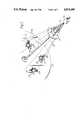
- FIG. 1is a perspective view of a part cut-away piece of cable made by a method, according to the present invention
- FIG. 2is a perspective view of part of a planetary strander used in the making of the cable of FIG. 1,
- FIG. 3is a schematic cross-sectional view of the crush-resistant tube of a piece of cable made using a modification of the method employed in the manufacture of the cable of FIG. 1, and
- FIG. 4is a sectional view of a cable whose crush-resistant tube is made using a further modification of the method employed in the manufacture of the cable of FIG. 1.
- An optical fibre package 20 for enclosure within the crush-resistant tube to be made by the method of the present inventiontypically comprises an optical fibre 11 encased within one or more plastics protective layers 12.
- the plastics packaged fibremay be encased loosely within a metal tube 13 that provides a hermetic barrier.
- the crush-resistant tubeis provided using a planetary strander.
- This stranderhas a hollow rotating shaft 21 through which the optical fibre package 20 is fed. Secured to this shaft is a plate 22 loaded with a set of spools 23 of circular cross-section wire. Wires 24 from these spools are paid-off and drawn through individual dies 25 which are mounted on cradles 26 that carry the spools 23 of the planetary strander. These dies 13 are employed to work the individual wires 24, changing their cross-section from circular symmetry into a non-circular form that will cause the wires to lock together in a stable crush-resistant manner when they are helically stranded by the planetary strander to form a tube.
- a convenient cross-section to which to work the fibresis that of a regular hexagon.
- Control over the laying-up of the wiresis exercised by passing them through individual apertures in a lay-plate 27 that rotates with the shaft 20, and bringing them down into contact with each other by passing them through a stationary closing die 28.
- the pitch of the helical stranding of the wires 24is controlled by relating the rotational speed of the shaft 21 to the linear speed at which the wires are drawn through the closing die 28.
- the resulting crush-resistant tubeis then usually provided with an extruded plastics sheath. This sheath is conveniently provided on-line with the laying-up of the wires to form the crush-resistant tube. Such a sheath is depicted at 15 in FIG. 1. In this figure the six wires 24 that go to make the crush-resistant tube have been worked by the dies 25 from circular cross-section into hexagonal cross-section.
- the use of individual dies 25 for each wire 24is dispensed with, and instead their place is taken by fairings which allow free passage of the wires through their orifices.
- the individual wiresare worked into a non-circular cross-section in the closing die 28.
- the closing diemay co-operate with a point (not separately illustrated) in such a way as to define an annulus through which the wires have the pass.
- the dimensions of this annulusare such as to cause the individual wires to be deformed by contact with the point, with the die, and with the other members of the set, from a circular cross-section, as depicted by the broken line 30 (FIG. 3), to a wedge-shaped one 31.
- the pointis hollow so as to permit the optical fibre package to pass freely through its middle.
- the use of the co-operating pointis not essential for deformation of the wires to be accomplished by means of the closing die 28, and in FIG. 4 there is depicted a tracing of a photograph of a section of cable whose crush-resistant tube is formed of six copper wires deformed from circular cross-section by the closing die without the aid of a co-operating point.
- the hermetic barrier tube 13has an external diameter of 0.8mm.
- the six wedge-shaped wires 24 co-operating to form the crush-resistant tubeare formed from 16 gauge British Standard Wire gauge (64.00 mils diameter) copper wire, and the closing die provides the resulting crush-resistant tube with an external diameter of 4.lmm.
- On line with the laying-up of this tubeit is provided with a first extruded layer 40 of semiconductive polymer and a second extruded layer 41 of medium density polyethylene.
- the material of the tubeis also required to provide a significant proportion of the tensile strength of the cable, it will generally be preferred to use wire of a material with a higher tensile modulus than copper.
- a preferred materialis steel.
- Steel wiresmay be copper-clad in order to reduce the force necessary to draw them through the dies or die by virtue of the more ductile surface coating on the wires.
- a crush-resistance tube constructed from wires composed entirely of coppermay generally be preferred.
Landscapes
- Physics & Mathematics (AREA)
- General Physics & Mathematics (AREA)
- Optics & Photonics (AREA)
- Engineering & Computer Science (AREA)
- Manufacturing & Machinery (AREA)
- Communication Cables (AREA)
- Light Guides In General And Applications Therefor (AREA)
Abstract
Description
Claims (5)
Applications Claiming Priority (2)
| Application Number | Priority Date | Filing Date | Title |
|---|---|---|---|
| GB8700681 | 1987-01-13 | ||
| GB8700681AGB2199961B (en) | 1987-01-13 | 1987-01-13 | Optical fibre cable containing non-circular cross section wires. |
Publications (1)
| Publication Number | Publication Date |
|---|---|
| US4915490Atrue US4915490A (en) | 1990-04-10 |
Family
ID=10610608
Family Applications (1)
| Application Number | Title | Priority Date | Filing Date |
|---|---|---|---|
| US07/363,487Expired - Fee RelatedUS4915490A (en) | 1987-01-13 | 1989-06-08 | Optical fibre cable with crush-resistant tube |
Country Status (2)
| Country | Link |
|---|---|
| US (1) | US4915490A (en) |
| GB (1) | GB2199961B (en) |
Cited By (17)
| Publication number | Priority date | Publication date | Assignee | Title |
|---|---|---|---|---|
| US4984869A (en)* | 1988-09-09 | 1991-01-15 | Satcables (Societe En Nom Collectif) | Optical fibre cable and method of making same |
| US5155788A (en)* | 1990-08-29 | 1992-10-13 | American Telephone & Telegraph Company | Optical fiber disposed in and decoupled from a reinforcing member |
| US5463711A (en)* | 1994-07-29 | 1995-10-31 | At&T Ipm Corp. | Submarine cable having a centrally located tube containing optical fibers |
| US5649043A (en)* | 1995-07-25 | 1997-07-15 | Alcatel Na Cable Systems, Inc. | Optical fiber cable having truncated triangular profile tubes |
| US6169834B1 (en)* | 1998-05-13 | 2001-01-02 | Alcatel | Slotted composite cable having a cable housing with a tubular opening for copper pairs and a slot for an optical fiber |
| US20040097965A1 (en)* | 2002-11-19 | 2004-05-20 | Gardeski Kenneth C. | Multilumen body for an implantable medical device |
| US20050004642A1 (en)* | 1998-11-09 | 2005-01-06 | Medtronic, Inc. | Implantable medical lead including overlay |
| US20080031578A1 (en)* | 2006-08-02 | 2008-02-07 | Joseph Varkey | Packaging for encasing an optical fiber in a cable |
| US20100116510A1 (en)* | 2006-08-02 | 2010-05-13 | Joseph Varkey | Packaging for encasing an optical fiber in a cable |
| WO2017167319A1 (en)* | 2016-03-31 | 2017-10-05 | Predistribuce, A.S. | Combined power cable |
| US10062476B2 (en) | 2012-06-28 | 2018-08-28 | Schlumberger Technology Corporation | High power opto-electrical cable with multiple power and telemetry paths |
| US10080862B2 (en) | 2015-08-14 | 2018-09-25 | Medtronic, Inc. | Tubular bodies for medical delivery devices and related manufacturing methods |
| US10087717B2 (en) | 2011-10-17 | 2018-10-02 | Schlumberger Technology Corporation | Dual use cable with fiber optics for use in wellbore operations |
| US20190097351A1 (en)* | 2017-09-23 | 2019-03-28 | Luxshare Precision Industry Co., Ltd. | Round cable |
| CN110140259A (en)* | 2016-12-05 | 2019-08-16 | 莱尼电缆有限公司 | Route and method for manufacturing route |
| US10522271B2 (en) | 2016-06-09 | 2019-12-31 | Schlumberger Technology Corporation | Compression and stretch resistant components and cables for oilfield applications |
| US11725468B2 (en) | 2015-01-26 | 2023-08-15 | Schlumberger Technology Corporation | Electrically conductive fiber optic slickline for coiled tubing operations |
Families Citing this family (5)
| Publication number | Priority date | Publication date | Assignee | Title |
|---|---|---|---|---|
| GB2199961B (en)* | 1987-01-13 | 1990-09-26 | Stc Plc | Optical fibre cable containing non-circular cross section wires. |
| US4938560A (en)* | 1988-05-17 | 1990-07-03 | At&T Bell Laboratories | Animal-resistant cable |
| DE4206652A1 (en)* | 1992-03-03 | 1993-09-09 | Siemens Ag | OPTICAL CABLE AND METHOD FOR THE PRODUCTION THEREOF |
| KR100217717B1 (en)* | 1996-09-16 | 1999-09-01 | 윤종용 | Optical cable |
| AT518541B1 (en)* | 2016-05-09 | 2017-11-15 | Teufelberger Seil Ges M B H | steel cable |
Citations (20)
| Publication number | Priority date | Publication date | Assignee | Title |
|---|---|---|---|---|
| US3131469A (en)* | 1960-03-21 | 1964-05-05 | Tyler Wayne Res Corp | Process of producing a unitary multiple wire strand |
| US3234722A (en)* | 1963-04-12 | 1966-02-15 | American Chain & Cable Co | Compacted stranded cable |
| US3444684A (en)* | 1967-01-10 | 1969-05-20 | Southwire Co | Method of forming a multi-strand cable |
| US3778993A (en)* | 1971-12-07 | 1973-12-18 | M Glushko | Method of manufacturing twisted wire products |
| US3872659A (en)* | 1971-04-26 | 1975-03-25 | British Ropes Ltd | Method and apparatus for production of tubular strand and rope |
| US3956877A (en)* | 1975-04-02 | 1976-05-18 | American Chain & Cable Company, Inc. | Spliceless cable and method of forming same |
| GB1486764A (en)* | 1976-07-27 | 1977-09-21 | Standard Telephones Cables Ltd | Cable |
| GB2017968A (en)* | 1978-03-31 | 1979-10-10 | Kokusai Denshin Denwa Co Ltd | Submarine optical fibre cable |
| GB2043936A (en)* | 1978-12-12 | 1980-10-08 | Cables De Lyon Geoffroy Delore | Undersea optical fibre telecommunications cable and a method and apparatus for manufacture thereof |
| GB1598438A (en)* | 1977-05-13 | 1981-09-23 | Bicc Ltd | Overhead electric transmission systems |
| GB2088584A (en)* | 1980-11-28 | 1982-06-09 | Pirelli Cavi Spa | Overhead electric cable |
| GB2090995A (en)* | 1981-01-13 | 1982-07-21 | Standard Telephones Cables Ltd | Pressure-resistant Cable Strength Member |
| EP0060061A1 (en)* | 1981-03-06 | 1982-09-15 | Bridon Limited | Strain cables |
| GB2105484A (en)* | 1981-09-01 | 1983-03-23 | Standard Telephones Cables Ltd | Optical fibre cables |
| WO1984000820A1 (en)* | 1982-08-17 | 1984-03-01 | Chevron Res | A hermetically sealed tube incorporating an optical fiber surrounded by an armored cable |
| GB2125984A (en)* | 1982-07-19 | 1984-03-14 | Bicc Plc | An improved flexible elongate body |
| GB2165662A (en)* | 1984-10-08 | 1986-04-16 | Ass Elect Ind | Optical cable |
| GB2173034A (en)* | 1985-03-01 | 1986-10-01 | Int Standard Electric Corp | Oil well logging cable |
| GB2199961A (en)* | 1987-01-13 | 1988-07-20 | Stc Plc | Optical fibre cable containing non circular cross section wires |
| US4778246A (en)* | 1985-05-15 | 1988-10-18 | Acco Babcock Industries, Inc. | High tensile strength compacted towing cable with signal transmission element and method of making the same |
Family Cites Families (1)
| Publication number | Priority date | Publication date | Assignee | Title |
|---|---|---|---|---|
| JPS622412A (en)* | 1985-06-28 | 1987-01-08 | 株式会社フジクラ | Optical fiber composite overhead line |
- 1987
- 1987-01-13GBGB8700681Apatent/GB2199961B/ennot_activeExpired - Fee Related
- 1989
- 1989-06-08USUS07/363,487patent/US4915490A/ennot_activeExpired - Fee Related
Patent Citations (20)
| Publication number | Priority date | Publication date | Assignee | Title |
|---|---|---|---|---|
| US3131469A (en)* | 1960-03-21 | 1964-05-05 | Tyler Wayne Res Corp | Process of producing a unitary multiple wire strand |
| US3234722A (en)* | 1963-04-12 | 1966-02-15 | American Chain & Cable Co | Compacted stranded cable |
| US3444684A (en)* | 1967-01-10 | 1969-05-20 | Southwire Co | Method of forming a multi-strand cable |
| US3872659A (en)* | 1971-04-26 | 1975-03-25 | British Ropes Ltd | Method and apparatus for production of tubular strand and rope |
| US3778993A (en)* | 1971-12-07 | 1973-12-18 | M Glushko | Method of manufacturing twisted wire products |
| US3956877A (en)* | 1975-04-02 | 1976-05-18 | American Chain & Cable Company, Inc. | Spliceless cable and method of forming same |
| GB1486764A (en)* | 1976-07-27 | 1977-09-21 | Standard Telephones Cables Ltd | Cable |
| GB1598438A (en)* | 1977-05-13 | 1981-09-23 | Bicc Ltd | Overhead electric transmission systems |
| GB2017968A (en)* | 1978-03-31 | 1979-10-10 | Kokusai Denshin Denwa Co Ltd | Submarine optical fibre cable |
| GB2043936A (en)* | 1978-12-12 | 1980-10-08 | Cables De Lyon Geoffroy Delore | Undersea optical fibre telecommunications cable and a method and apparatus for manufacture thereof |
| GB2088584A (en)* | 1980-11-28 | 1982-06-09 | Pirelli Cavi Spa | Overhead electric cable |
| GB2090995A (en)* | 1981-01-13 | 1982-07-21 | Standard Telephones Cables Ltd | Pressure-resistant Cable Strength Member |
| EP0060061A1 (en)* | 1981-03-06 | 1982-09-15 | Bridon Limited | Strain cables |
| GB2105484A (en)* | 1981-09-01 | 1983-03-23 | Standard Telephones Cables Ltd | Optical fibre cables |
| GB2125984A (en)* | 1982-07-19 | 1984-03-14 | Bicc Plc | An improved flexible elongate body |
| WO1984000820A1 (en)* | 1982-08-17 | 1984-03-01 | Chevron Res | A hermetically sealed tube incorporating an optical fiber surrounded by an armored cable |
| GB2165662A (en)* | 1984-10-08 | 1986-04-16 | Ass Elect Ind | Optical cable |
| GB2173034A (en)* | 1985-03-01 | 1986-10-01 | Int Standard Electric Corp | Oil well logging cable |
| US4778246A (en)* | 1985-05-15 | 1988-10-18 | Acco Babcock Industries, Inc. | High tensile strength compacted towing cable with signal transmission element and method of making the same |
| GB2199961A (en)* | 1987-01-13 | 1988-07-20 | Stc Plc | Optical fibre cable containing non circular cross section wires |
Cited By (23)
| Publication number | Priority date | Publication date | Assignee | Title |
|---|---|---|---|---|
| US4984869A (en)* | 1988-09-09 | 1991-01-15 | Satcables (Societe En Nom Collectif) | Optical fibre cable and method of making same |
| US5155788A (en)* | 1990-08-29 | 1992-10-13 | American Telephone & Telegraph Company | Optical fiber disposed in and decoupled from a reinforcing member |
| US5463711A (en)* | 1994-07-29 | 1995-10-31 | At&T Ipm Corp. | Submarine cable having a centrally located tube containing optical fibers |
| US5649043A (en)* | 1995-07-25 | 1997-07-15 | Alcatel Na Cable Systems, Inc. | Optical fiber cable having truncated triangular profile tubes |
| US6169834B1 (en)* | 1998-05-13 | 2001-01-02 | Alcatel | Slotted composite cable having a cable housing with a tubular opening for copper pairs and a slot for an optical fiber |
| US20050004642A1 (en)* | 1998-11-09 | 2005-01-06 | Medtronic, Inc. | Implantable medical lead including overlay |
| US20040097965A1 (en)* | 2002-11-19 | 2004-05-20 | Gardeski Kenneth C. | Multilumen body for an implantable medical device |
| US7130700B2 (en)* | 2002-11-19 | 2006-10-31 | Medtronic, Inc. | Multilumen body for an implantable medical device |
| US9201207B2 (en) | 2006-08-02 | 2015-12-01 | Schlumberger Technology Corporation | Packaging for encasing an optical fiber in a cable |
| US20100116510A1 (en)* | 2006-08-02 | 2010-05-13 | Joseph Varkey | Packaging for encasing an optical fiber in a cable |
| US20080031578A1 (en)* | 2006-08-02 | 2008-02-07 | Joseph Varkey | Packaging for encasing an optical fiber in a cable |
| US10087717B2 (en) | 2011-10-17 | 2018-10-02 | Schlumberger Technology Corporation | Dual use cable with fiber optics for use in wellbore operations |
| US10062476B2 (en) | 2012-06-28 | 2018-08-28 | Schlumberger Technology Corporation | High power opto-electrical cable with multiple power and telemetry paths |
| US11725468B2 (en) | 2015-01-26 | 2023-08-15 | Schlumberger Technology Corporation | Electrically conductive fiber optic slickline for coiled tubing operations |
| US10080862B2 (en) | 2015-08-14 | 2018-09-25 | Medtronic, Inc. | Tubular bodies for medical delivery devices and related manufacturing methods |
| WO2017167319A1 (en)* | 2016-03-31 | 2017-10-05 | Predistribuce, A.S. | Combined power cable |
| PL71351Y1 (en)* | 2016-03-31 | 2020-04-30 | Predistribuce A S | Combined power cable |
| US10522271B2 (en) | 2016-06-09 | 2019-12-31 | Schlumberger Technology Corporation | Compression and stretch resistant components and cables for oilfield applications |
| US11335478B2 (en) | 2016-06-09 | 2022-05-17 | Schlumberger Technology Corporation | Compression and stretch resistant components and cables for oilfield applications |
| US11776712B2 (en) | 2016-06-09 | 2023-10-03 | Schlumberger Technology Corporation | Compression and stretch resistant components and cables for oilfield applications |
| CN110140259A (en)* | 2016-12-05 | 2019-08-16 | 莱尼电缆有限公司 | Route and method for manufacturing route |
| US10424868B2 (en)* | 2017-09-23 | 2019-09-24 | Luxshare Precision Industry Co., Ltd. | Round cable |
| US20190097351A1 (en)* | 2017-09-23 | 2019-03-28 | Luxshare Precision Industry Co., Ltd. | Round cable |
Also Published As
| Publication number | Publication date |
|---|---|
| GB2199961B (en) | 1990-09-26 |
| GB2199961A (en) | 1988-07-20 |
| GB8700681D0 (en) | 1987-02-18 |
Similar Documents
| Publication | Publication Date | Title |
|---|---|---|
| US4915490A (en) | Optical fibre cable with crush-resistant tube | |
| US4166670A (en) | Optical fiber cable | |
| CA1187147A (en) | Cable comprising interlocking metallic support members | |
| US4606604A (en) | Optical fiber submarine cable and method of making | |
| US4997257A (en) | Optical cable | |
| EP0139166B1 (en) | Optical fiber cable | |
| DE2355855A1 (en) | OPTICAL CABLE | |
| CH656970A5 (en) | HIGHLY FLEXIBLE INSULATED ELECTRIC CABLE, METHOD FOR THE PRODUCTION AND USE OF THE CABLE. | |
| CA1090636A (en) | Fiber optic cable and method of making same | |
| US3760093A (en) | Compact conductor | |
| US3823542A (en) | Method of making compact conductor | |
| JP3805407B2 (en) | Optical cable having U-shaped carrier with improved crushing performance | |
| EP0840331A1 (en) | Flexible line | |
| DE2948757A1 (en) | REINFORCED OPTICAL FIBER LADDER AND OPTICAL FIBER CABLE | |
| DE2509547A1 (en) | Optic fibre transmission cable construction - has steel cord reinforcement of elastic-sided inner chambers for stress reduction | |
| US4809492A (en) | Torsionally balanced wire rope or cable | |
| DE2511019C2 (en) | Basic element for the construction of optical cables | |
| EP0311751B1 (en) | Flexible power line, particularly heavy-duty cable with integrated lightwave conductors. | |
| GB2164471A (en) | Optical fibre cables | |
| EP0819312B1 (en) | Power cable with optical fibers | |
| EP0211107B1 (en) | Non-metallic waveguide cable with a cable core | |
| DE3810714C2 (en) | ||
| DE2508315A1 (en) | Optical cable for signal transmission - has several optical transmission elements applied on strong core of stranded steel wires | |
| JPS6143683B2 (en) | ||
| DE19820075C2 (en) | Optical cable for message transmission |
Legal Events
| Date | Code | Title | Description |
|---|---|---|---|
| AS | Assignment | Owner name:STC PLC, 10, MALTRAVERS STREET, LONDON. WC2R 3HA, Free format text:ASSIGNMENT OF ASSIGNORS INTEREST.;ASSIGNORS:RAMSAY, MELVIN M.;BLACK, PHILIP W.;JONES, IOWA D. L.;REEL/FRAME:005088/0516;SIGNING DATES FROM 19890524 TO 19890530 | |
| FEPP | Fee payment procedure | Free format text:PAYOR NUMBER ASSIGNED (ORIGINAL EVENT CODE: ASPN); ENTITY STATUS OF PATENT OWNER: LARGE ENTITY | |
| FPAY | Fee payment | Year of fee payment:4 | |
| FEPP | Fee payment procedure | Free format text:PAYOR NUMBER ASSIGNED (ORIGINAL EVENT CODE: ASPN); ENTITY STATUS OF PATENT OWNER: LARGE ENTITY Free format text:PAYER NUMBER DE-ASSIGNED (ORIGINAL EVENT CODE: RMPN); ENTITY STATUS OF PATENT OWNER: LARGE ENTITY | |
| AS | Assignment | Owner name:ANSAFONE INVESTMENT BV, NETHERLANDS Free format text:ASSIGNMENT OF ASSIGNORS INTEREST;ASSIGNORS:STC LIMITED;STC SUBMARINE SYSTEMS LIMITED;NORTHERN TELECOM LIMITED;REEL/FRAME:007427/0337;SIGNING DATES FROM 19940301 TO 19940303 Owner name:ALCATEL SUBMARINE SYSTEMS B.V., NETHERLANDS Free format text:CHANGE OF NAME;ASSIGNOR:ANSAFONE INVESTMENT B.V.;REEL/FRAME:007427/0341 Effective date:19940714 | |
| FPAY | Fee payment | Year of fee payment:8 | |
| REMI | Maintenance fee reminder mailed | ||
| LAPS | Lapse for failure to pay maintenance fees | ||
| STCH | Information on status: patent discontinuation | Free format text:PATENT EXPIRED DUE TO NONPAYMENT OF MAINTENANCE FEES UNDER 37 CFR 1.362 | |
| FP | Lapsed due to failure to pay maintenance fee | Effective date:20020410 |