US4915019A - Mechanism for transforming the reciprocal movement of a piston into a circular movement of a shaft - Google Patents
Mechanism for transforming the reciprocal movement of a piston into a circular movement of a shaftDownload PDFInfo
- Publication number
- US4915019A US4915019AUS07/050,128US5012887AUS4915019AUS 4915019 AUS4915019 AUS 4915019AUS 5012887 AUS5012887 AUS 5012887AUS 4915019 AUS4915019 AUS 4915019A
- Authority
- US
- United States
- Prior art keywords
- shaft
- pistons
- piston
- racks
- toothed sector
- Prior art date
- Legal status (The legal status is an assumption and is not a legal conclusion. Google has not performed a legal analysis and makes no representation as to the accuracy of the status listed.)
- Expired - Fee Related
Links
Images

Classifications
- F—MECHANICAL ENGINEERING; LIGHTING; HEATING; WEAPONS; BLASTING
- F01—MACHINES OR ENGINES IN GENERAL; ENGINE PLANTS IN GENERAL; STEAM ENGINES
- F01B—MACHINES OR ENGINES, IN GENERAL OR OF POSITIVE-DISPLACEMENT TYPE, e.g. STEAM ENGINES
- F01B9/00—Reciprocating-piston machines or engines characterised by connections between pistons and main shafts, not specific to groups F01B1/00 - F01B7/00
- F01B9/04—Reciprocating-piston machines or engines characterised by connections between pistons and main shafts, not specific to groups F01B1/00 - F01B7/00 with rotary main shaft other than crankshaft
- F01B9/06—Reciprocating-piston machines or engines characterised by connections between pistons and main shafts, not specific to groups F01B1/00 - F01B7/00 with rotary main shaft other than crankshaft the piston motion being transmitted by curved surfaces
- F—MECHANICAL ENGINEERING; LIGHTING; HEATING; WEAPONS; BLASTING
- F01—MACHINES OR ENGINES IN GENERAL; ENGINE PLANTS IN GENERAL; STEAM ENGINES
- F01B—MACHINES OR ENGINES, IN GENERAL OR OF POSITIVE-DISPLACEMENT TYPE, e.g. STEAM ENGINES
- F01B7/00—Machines or engines with two or more pistons reciprocating within same cylinder or within essentially coaxial cylinders
- F01B7/02—Machines or engines with two or more pistons reciprocating within same cylinder or within essentially coaxial cylinders with oppositely reciprocating pistons
- F01B7/04—Machines or engines with two or more pistons reciprocating within same cylinder or within essentially coaxial cylinders with oppositely reciprocating pistons acting on same main shaft
- F—MECHANICAL ENGINEERING; LIGHTING; HEATING; WEAPONS; BLASTING
- F01—MACHINES OR ENGINES IN GENERAL; ENGINE PLANTS IN GENERAL; STEAM ENGINES
- F01B—MACHINES OR ENGINES, IN GENERAL OR OF POSITIVE-DISPLACEMENT TYPE, e.g. STEAM ENGINES
- F01B9/00—Reciprocating-piston machines or engines characterised by connections between pistons and main shafts, not specific to groups F01B1/00 - F01B7/00
- F01B9/04—Reciprocating-piston machines or engines characterised by connections between pistons and main shafts, not specific to groups F01B1/00 - F01B7/00 with rotary main shaft other than crankshaft
- F01B9/047—Reciprocating-piston machines or engines characterised by connections between pistons and main shafts, not specific to groups F01B1/00 - F01B7/00 with rotary main shaft other than crankshaft with rack and pinion
- F—MECHANICAL ENGINEERING; LIGHTING; HEATING; WEAPONS; BLASTING
- F16—ENGINEERING ELEMENTS AND UNITS; GENERAL MEASURES FOR PRODUCING AND MAINTAINING EFFECTIVE FUNCTIONING OF MACHINES OR INSTALLATIONS; THERMAL INSULATION IN GENERAL
- F16H—GEARING
- F16H19/00—Gearings comprising essentially only toothed gears or friction members and not capable of conveying indefinitely-continuing rotary motion
- F16H19/02—Gearings comprising essentially only toothed gears or friction members and not capable of conveying indefinitely-continuing rotary motion for interconverting rotary or oscillating motion and reciprocating motion
- F16H19/04—Gearings comprising essentially only toothed gears or friction members and not capable of conveying indefinitely-continuing rotary motion for interconverting rotary or oscillating motion and reciprocating motion comprising a rack
- F16H19/043—Gearings comprising essentially only toothed gears or friction members and not capable of conveying indefinitely-continuing rotary motion for interconverting rotary or oscillating motion and reciprocating motion comprising a rack for converting reciprocating movement in a continuous rotary movement or vice versa, e.g. by opposite racks engaging intermittently for a part of the stroke
- Y—GENERAL TAGGING OF NEW TECHNOLOGICAL DEVELOPMENTS; GENERAL TAGGING OF CROSS-SECTIONAL TECHNOLOGIES SPANNING OVER SEVERAL SECTIONS OF THE IPC; TECHNICAL SUBJECTS COVERED BY FORMER USPC CROSS-REFERENCE ART COLLECTIONS [XRACs] AND DIGESTS
- Y10—TECHNICAL SUBJECTS COVERED BY FORMER USPC
- Y10T—TECHNICAL SUBJECTS COVERED BY FORMER US CLASSIFICATION
- Y10T74/00—Machine element or mechanism
- Y10T74/15—Intermittent grip type mechanical movement
- Y10T74/1526—Oscillation or reciprocation to intermittent unidirectional motion
- Y10T74/1532—Rack actuator
- Y10T74/1534—Multiple acting
- Y—GENERAL TAGGING OF NEW TECHNOLOGICAL DEVELOPMENTS; GENERAL TAGGING OF CROSS-SECTIONAL TECHNOLOGIES SPANNING OVER SEVERAL SECTIONS OF THE IPC; TECHNICAL SUBJECTS COVERED BY FORMER USPC CROSS-REFERENCE ART COLLECTIONS [XRACs] AND DIGESTS
- Y10—TECHNICAL SUBJECTS COVERED BY FORMER USPC
- Y10T—TECHNICAL SUBJECTS COVERED BY FORMER US CLASSIFICATION
- Y10T74/00—Machine element or mechanism
- Y10T74/18—Mechanical movements
- Y10T74/18056—Rotary to or from reciprocating or oscillating
- Y10T74/18248—Crank and slide
- Y10T74/18256—Slidable connections [e.g., scotch yoke]
- Y—GENERAL TAGGING OF NEW TECHNOLOGICAL DEVELOPMENTS; GENERAL TAGGING OF CROSS-SECTIONAL TECHNOLOGIES SPANNING OVER SEVERAL SECTIONS OF THE IPC; TECHNICAL SUBJECTS COVERED BY FORMER USPC CROSS-REFERENCE ART COLLECTIONS [XRACs] AND DIGESTS
- Y10—TECHNICAL SUBJECTS COVERED BY FORMER USPC
- Y10T—TECHNICAL SUBJECTS COVERED BY FORMER US CLASSIFICATION
- Y10T74/00—Machine element or mechanism
- Y10T74/19—Gearing
- Y10T74/1987—Rotary bodies
- Y10T74/19874—Mutilated
Definitions
- the inventionrelates to the transformation of a reciprocal movement obtained from a piston by the thrust of a fluid, into a rotary movement recoverable on a shaft or reciprocally.
- the link-crank assemblymakes it necessary to use different expedients such as ignition and exhaust advance, movement of the piston in accordance with a rigid mathematical law.
- the present inventionproposes overcoming these drawbacks and provides a device for transforming a reciprocal movement into a rotary movement which, while being of great mechanical simplicity, allows optimum efficiency to be obtained without requiring the use of ignition and exhaust advance of the thermal engines.
- the device of the inventionincludes essentially two racks connected to the piston of the engine and which drive alternately a toothed sector carried by the drive shaft, two cams being also carried by the drive shaft and serving as guides for four rollers fixed to the mobile rack-piston assembly.
- the second and last but one teeth of each of the racksare partially truncated, as well as the end teeth of this toothed sector cooperating with the racks.
- the profile of the camis designed so as to provide ignition only at the end of compression and so as to have a variation of the volume of the chamber, so of the pressure of the ideal mixture, during the whole combustion time.
- FIG. 1shows a device having two racks cooperating with a toothed sector
- FIG. 2shows a front and vertical sectional view of one of the cams fixed on the output shaft
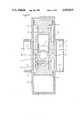
- FIG. 3shows one embodiment with two opposed pistons.
- FIG. 1there is shown the device of the invention formed of two racks 1, 2 integrally secured to pistons (not shown in this Figure) and moving as a single block for meshing alternately with a toothed sector 3 fixed on the output shaft.
- racks 1, 2have 9 teeth and the toothed sector 3 integrally secured to the output shaft has 8 teeth, for a pinion of the same modulus having 20 teeth.
- the second and last but one teeth of each rack 1, 2 as well as the end teeth of the toothed sector 3are truncated, as shown in FIG. 1.
- This Figureshows the toothed sector 3 in an intermediate position, separated from racks 1, 2.
- cams 4one of which is shown in FIG. 2, are fixed on the output shaft for taking over.
- a groove 5 formed in cam 4guides a roller fixed to the piston-rack assembly. Groove 5 is broken down into five zones:
- the linear speed of the pistonis constant and corresponds to the mean speed of link-crank drive systems. This linear speed may therefore be increased, while remaining below the jamming speed due to the friction of the segments on the cylinders, the rotational speed of the output shaft being increased in the same proportions.
- FIG. 3has been shown one embodiment with two opposed pistons.
- two half bodies 6are assembled together by four bolts 7 and sandwich therebetween two bronze slides 8 which guide the two racks 1, 2 joining the two pistons 9 together.
- On the output shaft 10are assembled the toothed sector 3 and cams 4, the groove 5 of these cams driving the pistons 9 through rollers 12 carried thereby.
- the cylinders inside which pistons 9 slideare shown by the two caps 13 which cover the two half bodies.
Landscapes
- Engineering & Computer Science (AREA)
- General Engineering & Computer Science (AREA)
- Mechanical Engineering (AREA)
- Transmission Devices (AREA)
- Reciprocating Pumps (AREA)
Abstract
Description
The invention relates to the transformation of a reciprocal movement obtained from a piston by the thrust of a fluid, into a rotary movement recoverable on a shaft or reciprocally.
Such transformation is traditionally obtained by a link-crank assembly with the drawbacks inherent in this system. In fact, the analysis of the force exerted on the link reveals a horizontal component, absorbing energy. In addition, for a constant rotational speed of the shaft, that of the piston follows a sinusoidal function, whence a reduced mean linear speed.
In use in thermal engines, the link-crank assembly makes it necessary to use different expedients such as ignition and exhaust advance, movement of the piston in accordance with a rigid mathematical law.
The present invention proposes overcoming these drawbacks and provides a device for transforming a reciprocal movement into a rotary movement which, while being of great mechanical simplicity, allows optimum efficiency to be obtained without requiring the use of ignition and exhaust advance of the thermal engines.
The device of the invention includes essentially two racks connected to the piston of the engine and which drive alternately a toothed sector carried by the drive shaft, two cams being also carried by the drive shaft and serving as guides for four rollers fixed to the mobile rack-piston assembly.
Advantageously, the second and last but one teeth of each of the racks are partially truncated, as well as the end teeth of this toothed sector cooperating with the racks.
The profile of the cam is designed so as to provide ignition only at the end of compression and so as to have a variation of the volume of the chamber, so of the pressure of the ideal mixture, during the whole combustion time.
Furthermore, a better exhaust and filling are obtained during the time when the piston is stopped at the end of its stroke, corresponding to a zone of the cam concentric with the axis of rotation of the output shaft.
For a better understanding of the invention, one embodiment thereof will be described hereafter with reference to the accompanying schematic drawings in which:
FIG. 1 shows a device having two racks cooperating with a toothed sector;
FIG. 2 shows a front and vertical sectional view of one of the cams fixed on the output shaft; and
FIG. 3 shows one embodiment with two opposed pistons.
In FIG. 1 there is shown the device of the invention formed of tworacks 1, 2 integrally secured to pistons (not shown in this Figure) and moving as a single block for meshing alternately with atoothed sector 3 fixed on the output shaft. In the example chosen, racks 1, 2 have 9 teeth and thetoothed sector 3 integrally secured to the output shaft has 8 teeth, for a pinion of the same modulus having 20 teeth. The second and last but one teeth of eachrack 1, 2 as well as the end teeth of thetoothed sector 3 are truncated, as shown in FIG. 1. This Figure shows thetoothed sector 3 in an intermediate position, separated fromracks 1, 2.
To provide drive continuity twocams 4, one of which is shown in FIG. 2, are fixed on the output shaft for taking over. Agroove 5 formed incam 4 guides a roller fixed to the piston-rack assembly. Groove 5 is broken down into five zones:
zone of angle α, corresponding to the simultaneous drive of the ouput shaft by cam and rack at a distance V,
zone of angle β, corresponding to a deceleration of the rack-piston assembly,
zone of angle γ, stopping of this assembly,
zone of angle δ, acceleration of the assembly,
zone of angle Ω, simultaneous drive by cam and rack at speed -V.
During the end of travel strokes, the possibility of modifying the path of the groove of the cams allows the speed of movement of the mobile assembly, and so the variation of the volume of the combustion chamber to be controlled at will, depending on the fuel used.
During the rack drive the linear speed of the piston is constant and corresponds to the mean speed of link-crank drive systems. This linear speed may therefore be increased, while remaining below the jamming speed due to the friction of the segments on the cylinders, the rotational speed of the output shaft being increased in the same proportions.
In FIG. 3 has been shown one embodiment with two opposed pistons. In this embodiment, two half bodies 6 are assembled together by fourbolts 7 and sandwich therebetween two bronze slides 8 which guide the tworacks 1, 2 joining the twopistons 9 together. On theoutput shaft 10 are assembled thetoothed sector 3 andcams 4, thegroove 5 of these cams driving thepistons 9 throughrollers 12 carried thereby. The cylinders inside whichpistons 9 slide are shown by the twocaps 13 which cover the two half bodies.
The operation will be immediately understood from the prceding description, the movement in one direction of the assembly formed bypistons 9 andracks 2, following the explosion in one of the cylinders, causing one of theracks 2 to mesh with thetoothed sector 3 and so rotatingshaft 10. At the end of this meshing period,cam 4 cooperates with theroller 12 of one of the pistons so as to ensure continuity of the drive, then the explosion occurs in the other cylinder causing the movement ofassembly sector 3 so as to continue the drive orshaft 10.
Claims (4)
1. A device for transforming a reciprocal movement of a piston into a continuous rotary movement of a shaft, which comprises:
(a) a pair of pistons, each said piston providing a stroke in an opposite direction;
(b) two racks, each rack integral with and travelling uniformly in response to a stroke from both of pistons;
(c) said shaft;
(d) a circular grear having a toothed sector fixed to said shaft and disposed between said two racks, said toothed sector being in meshing engagement with one of said racks during a stroke from one of said pistons in one direction and in meshing engagement with the other of said racks during a piston stroke from the other of said pistons in the opposite direction;
(e) two rollers disposed and fixed on opposite faces of each of said pistons, on the longitudinal axis thereof; and
(f) two cams fixed on said shaft, each cam having a groove having five different zones co-acting with one of said rollers one said zone being concentric with the rotational axis of said shaft and corresponding to the termination of the stroke of one of said pistons, said cams guiding said rollers.
2. Device according to claim 1, wherein the second and last but one teeth of said racks are partially truncated.
3. Device according to claim 1, wherein the end teeth of the toothed sector are partially truncated.
4. Device according to claim 2, wherein the end teeth of the toothed sector are partially truncated.
Applications Claiming Priority (2)
| Application Number | Priority Date | Filing Date | Title |
|---|---|---|---|
| FR8512436 | 1985-08-13 | ||
| FR8512436AFR2586280B1 (en) | 1985-08-13 | 1985-08-13 | MECHANISM FOR TRANSFORMING THE ALTERNATIVE MOTION OF A PISTON INTO A CIRCULAR MOTION OF A SHAFT |
Publications (1)
| Publication Number | Publication Date |
|---|---|
| US4915019Atrue US4915019A (en) | 1990-04-10 |
Family
ID=9322255
Family Applications (1)
| Application Number | Title | Priority Date | Filing Date |
|---|---|---|---|
| US07/050,128Expired - Fee RelatedUS4915019A (en) | 1985-08-13 | 1986-08-08 | Mechanism for transforming the reciprocal movement of a piston into a circular movement of a shaft |
Country Status (8)
| Country | Link |
|---|---|
| US (1) | US4915019A (en) |
| EP (1) | EP0233905B1 (en) |
| JP (1) | JPS63502048A (en) |
| CA (1) | CA1305338C (en) |
| DE (1) | DE3668362D1 (en) |
| ES (1) | ES2001507A6 (en) |
| FR (1) | FR2586280B1 (en) |
| WO (1) | WO1987001167A1 (en) |
Cited By (17)
| Publication number | Priority date | Publication date | Assignee | Title |
|---|---|---|---|---|
| US5078017A (en)* | 1990-05-04 | 1992-01-07 | Balanced Engines, Inc. | Motion translation device of scotch yoke type |
| US5351567A (en)* | 1993-11-08 | 1994-10-04 | Brackett Douglas C | Motion arrester for a conjugate drive mechanism |
| US5375566A (en)* | 1993-11-08 | 1994-12-27 | Brackett; Douglas C. | Internal combustion engine with improved cycle dynamics |
| US5431130A (en)* | 1993-11-08 | 1995-07-11 | Brackett; Douglas C. | Internal combustion engine with stroke specialized cylinders |
| US5445039A (en)* | 1994-03-18 | 1995-08-29 | Brackett; Douglas C. | Conjugate drive mechanism |
| US5513541A (en)* | 1994-03-18 | 1996-05-07 | Brackett; Douglas C. | Conjugate drive mechanism |
| US5546821A (en)* | 1993-11-08 | 1996-08-20 | Brackett; Douglas C. | Motion arrester for a conjugate drive mechanism |
| US5546897A (en)* | 1993-11-08 | 1996-08-20 | Brackett; Douglas C. | Internal combustion engine with stroke specialized cylinders |
| US5560327A (en)* | 1993-11-08 | 1996-10-01 | Brackett; Douglas C. | Internal combustion engine with improved cycle dynamics |
| RU2155269C1 (en)* | 1999-09-23 | 2000-08-27 | Ахунов Рашид Габдулназипович | Piston machine |
| US20040261750A1 (en)* | 2003-06-20 | 2004-12-30 | 3Rd Millennium Solutions, Ltd. | Internal combustion engine having dual piston cylinders and linear drive arrangement |
| US20070148016A1 (en)* | 2005-12-22 | 2007-06-28 | Newport Medical Instruments, Inc. | Reciprocating drive apparatus and method |
| CN100419213C (en)* | 2005-01-21 | 2008-09-17 | 刘战国 | Pinion-and-rack driving type engine |
| US20110197516A1 (en)* | 2010-02-17 | 2011-08-18 | Keihin Corporation | Sliding door device |
| US9611805B2 (en) | 2012-06-28 | 2017-04-04 | Oxford Two Stroke Limited | Piston arrangement and internal combustion engine |
| US9964030B1 (en)* | 2016-09-09 | 2018-05-08 | Nolton C. Johnson, Jr. | Tethered piston engine |
| WO2018210163A1 (en)* | 2017-05-18 | 2018-11-22 | 郑安庆 | Reciprocating linear motion and rotation motion transforming device, and cylinder device |
Families Citing this family (10)
| Publication number | Priority date | Publication date | Assignee | Title |
|---|---|---|---|---|
| KR910002899B1 (en)* | 1988-04-22 | 1991-05-09 | 박영근 | Internal combustion engine using rotary-reciprocating device |
| DE19538798A1 (en)* | 1995-10-18 | 1997-04-24 | Schwab Christian Dipl Designer | Rack gearing to convert reciprocating motion into rotary motion |
| RU2131528C1 (en)* | 1997-10-29 | 1999-06-10 | Смердов Геннадий Георгиевич | Internal combustion engine |
| FR2908854B1 (en)* | 2006-11-16 | 2009-01-16 | Jean Claude Keromnes | ALTERNATIVE MOTION CONVERSION MECHANISM IN ROTARY AND RECIPROCAL |
| FR2921694A1 (en)* | 2007-10-02 | 2009-04-03 | Jean Claude Keromnes | Heat engine e.g. double crankshaft and multi-cylinder two-stroke diesel engine, for e.g. power plant, has pistons whose alternating motion is transformed into rotary motion via mechanism constituted of toothed pinion intermeshed in cage |
| US8327819B2 (en)* | 2008-07-23 | 2012-12-11 | Cv Group, Llc | Constant velocity engine/technology |
| WO2010043231A1 (en)* | 2008-10-14 | 2010-04-22 | Lopez Jorge Vicente | Rack and pinion motor |
| FR3023893B1 (en)* | 2014-07-15 | 2017-10-20 | Andre Prieur | GEAR MECHANISM TO REDUCE UNDESIRABLE LATERAL EFFORTS |
| CN108757172A (en)* | 2018-05-21 | 2018-11-06 | 浙江大学 | A kind of half gear engine of four cylinders linkage |
| CN108798883A (en)* | 2018-06-13 | 2018-11-13 | 浙江大学 | A kind of novel horizontal gear rack engine |
Citations (9)
| Publication number | Priority date | Publication date | Assignee | Title |
|---|---|---|---|---|
| BE516059A (en)* | 1951-12-11 | |||
| GB190400068A (en)* | 1904-01-01 | 1904-11-24 | Edward Ellis Jackson | Improvements in Mechanism for Converting Substantially Continuous Circular Motion into Intermittent Reciprocating motion, or the Reverse |
| US1346139A (en)* | 1919-05-09 | 1920-07-13 | Robert W J Smith | Power-transmitting mechanism |
| DE374054C (en)* | 1921-01-11 | 1923-04-19 | Johannes Anton Beckmann | Gear for converting a straight back and forth movement into a uniform rotating movement |
| FR612889A (en)* | 1925-09-16 | 1926-11-03 | New device for transforming reciprocating motion into circular motion and vice versa | |
| GB516436A (en)* | 1938-06-24 | 1940-01-02 | Timothy Taylor | Improvements in and relating to driving gear for locomotives and other vehicles and engines |
| GB540986A (en)* | 1940-05-07 | 1941-11-07 | Timothy Taylor | Improvements in or relating to driving gear for locomotives and other vehicles and engines |
| US2513514A (en)* | 1945-10-08 | 1950-07-04 | Robert A Poage | Piston and crankshaft connecting means for internal-combustion engines |
| DE2936004A1 (en)* | 1979-09-06 | 1981-04-16 | Klöckner-Humboldt-Deutz AG, 5000 Köln | Rotary drive with alternate cam drives - has coaxial gears sequentially driven by half toothed cams |
Family Cites Families (3)
| Publication number | Priority date | Publication date | Assignee | Title |
|---|---|---|---|---|
| FR358129A (en)* | 1905-08-25 | 1906-01-29 | Fred Nevell Livingston | Mechanism for transforming reciprocating motion into continuous rotary motion and vice versa |
| FR33075E (en)* | 1927-03-03 | 1928-06-12 | Rack and pinion device for increasing the efficiency of piston engines, pumps and the like | |
| FR2093119A5 (en)* | 1970-06-03 | 1972-01-28 | Fuster Antoine |
- 1985
- 1985-08-13FRFR8512436Apatent/FR2586280B1/ennot_activeExpired - Lifetime
- 1986
- 1986-08-08USUS07/050,128patent/US4915019A/ennot_activeExpired - Fee Related
- 1986-08-08JPJP61504412Apatent/JPS63502048A/enactivePending
- 1986-08-08EPEP86904848Apatent/EP0233905B1/ennot_activeExpired - Lifetime
- 1986-08-08DEDE8686904848Tpatent/DE3668362D1/ennot_activeExpired - Fee Related
- 1986-08-08WOPCT/FR1986/000283patent/WO1987001167A1/enactiveIP Right Grant
- 1986-08-12CACA000515773Apatent/CA1305338C/ennot_activeExpired - Lifetime
- 1986-08-12ESES8601042Apatent/ES2001507A6/ennot_activeExpired
Patent Citations (9)
| Publication number | Priority date | Publication date | Assignee | Title |
|---|---|---|---|---|
| GB190400068A (en)* | 1904-01-01 | 1904-11-24 | Edward Ellis Jackson | Improvements in Mechanism for Converting Substantially Continuous Circular Motion into Intermittent Reciprocating motion, or the Reverse |
| US1346139A (en)* | 1919-05-09 | 1920-07-13 | Robert W J Smith | Power-transmitting mechanism |
| DE374054C (en)* | 1921-01-11 | 1923-04-19 | Johannes Anton Beckmann | Gear for converting a straight back and forth movement into a uniform rotating movement |
| FR612889A (en)* | 1925-09-16 | 1926-11-03 | New device for transforming reciprocating motion into circular motion and vice versa | |
| GB516436A (en)* | 1938-06-24 | 1940-01-02 | Timothy Taylor | Improvements in and relating to driving gear for locomotives and other vehicles and engines |
| GB540986A (en)* | 1940-05-07 | 1941-11-07 | Timothy Taylor | Improvements in or relating to driving gear for locomotives and other vehicles and engines |
| US2513514A (en)* | 1945-10-08 | 1950-07-04 | Robert A Poage | Piston and crankshaft connecting means for internal-combustion engines |
| BE516059A (en)* | 1951-12-11 | |||
| DE2936004A1 (en)* | 1979-09-06 | 1981-04-16 | Klöckner-Humboldt-Deutz AG, 5000 Köln | Rotary drive with alternate cam drives - has coaxial gears sequentially driven by half toothed cams |
Cited By (25)
| Publication number | Priority date | Publication date | Assignee | Title |
|---|---|---|---|---|
| US5078017A (en)* | 1990-05-04 | 1992-01-07 | Balanced Engines, Inc. | Motion translation device of scotch yoke type |
| US5351567A (en)* | 1993-11-08 | 1994-10-04 | Brackett Douglas C | Motion arrester for a conjugate drive mechanism |
| US5375566A (en)* | 1993-11-08 | 1994-12-27 | Brackett; Douglas C. | Internal combustion engine with improved cycle dynamics |
| US5431130A (en)* | 1993-11-08 | 1995-07-11 | Brackett; Douglas C. | Internal combustion engine with stroke specialized cylinders |
| US5546821A (en)* | 1993-11-08 | 1996-08-20 | Brackett; Douglas C. | Motion arrester for a conjugate drive mechanism |
| US5546897A (en)* | 1993-11-08 | 1996-08-20 | Brackett; Douglas C. | Internal combustion engine with stroke specialized cylinders |
| US5560327A (en)* | 1993-11-08 | 1996-10-01 | Brackett; Douglas C. | Internal combustion engine with improved cycle dynamics |
| US5445039A (en)* | 1994-03-18 | 1995-08-29 | Brackett; Douglas C. | Conjugate drive mechanism |
| US5513541A (en)* | 1994-03-18 | 1996-05-07 | Brackett; Douglas C. | Conjugate drive mechanism |
| US5575173A (en)* | 1994-03-18 | 1996-11-19 | Brackett; Douglas C. | Conjugate drive mechanism |
| RU2155269C1 (en)* | 1999-09-23 | 2000-08-27 | Ахунов Рашид Габдулназипович | Piston machine |
| US7201133B2 (en) | 2003-06-20 | 2007-04-10 | 3Rd Millennium Solutions, Ltd. | Internal combustion engine having dual piston cylinders and linear drive arrangement |
| US20040261750A1 (en)* | 2003-06-20 | 2004-12-30 | 3Rd Millennium Solutions, Ltd. | Internal combustion engine having dual piston cylinders and linear drive arrangement |
| CN100419213C (en)* | 2005-01-21 | 2008-09-17 | 刘战国 | Pinion-and-rack driving type engine |
| US20070148016A1 (en)* | 2005-12-22 | 2007-06-28 | Newport Medical Instruments, Inc. | Reciprocating drive apparatus and method |
| US7654802B2 (en)* | 2005-12-22 | 2010-02-02 | Newport Medical Instruments, Inc. | Reciprocating drive apparatus and method |
| US20110197516A1 (en)* | 2010-02-17 | 2011-08-18 | Keihin Corporation | Sliding door device |
| US8939821B2 (en) | 2010-02-17 | 2015-01-27 | Keihin Corporation | Sliding door device |
| US9611805B2 (en) | 2012-06-28 | 2017-04-04 | Oxford Two Stroke Limited | Piston arrangement and internal combustion engine |
| US10240559B2 (en) | 2012-06-28 | 2019-03-26 | Joost Engines Ltd. | Piston arrangement and internal combustion engine |
| US9964030B1 (en)* | 2016-09-09 | 2018-05-08 | Nolton C. Johnson, Jr. | Tethered piston engine |
| WO2018210163A1 (en)* | 2017-05-18 | 2018-11-22 | 郑安庆 | Reciprocating linear motion and rotation motion transforming device, and cylinder device |
| KR20200003412A (en)* | 2017-05-18 | 2020-01-09 | 안칭 정 | Linear reciprocating and rotary motion converters and cylinder units |
| US10927930B2 (en) | 2017-05-18 | 2021-02-23 | Anqing ZHENG | Reciprocating linear/rotational motion conversion device and cylinder device |
| KR102290673B1 (en) | 2017-05-18 | 2021-08-19 | 안칭 정 | Linear reciprocating/rotary motion converter and cylinder device |
Also Published As
| Publication number | Publication date |
|---|---|
| WO1987001167A1 (en) | 1987-02-26 |
| CA1305338C (en) | 1992-07-21 |
| DE3668362D1 (en) | 1990-02-22 |
| EP0233905A1 (en) | 1987-09-02 |
| EP0233905B1 (en) | 1990-01-17 |
| FR2586280A1 (en) | 1987-02-20 |
| JPS63502048A (en) | 1988-08-11 |
| ES2001507A6 (en) | 1988-06-01 |
| FR2586280B1 (en) | 1990-04-13 |
Similar Documents
| Publication | Publication Date | Title |
|---|---|---|
| US4915019A (en) | Mechanism for transforming the reciprocal movement of a piston into a circular movement of a shaft | |
| EP0368955B1 (en) | Motion conversion mechanism for use between rotating motions and reciprocating motions, and internal combustion engine using the same mechanism | |
| WO1995013463A1 (en) | Internal combustion engine with stroke specialized cylinders | |
| DE2502709A1 (en) | FOUR-STROKE COMBUSTION ENGINE WITH RADIAL CYLINDERS ROTATING IN A HOUSING | |
| US5560327A (en) | Internal combustion engine with improved cycle dynamics | |
| US4363299A (en) | Crankless internal combustion engine | |
| US3739755A (en) | Rotary engine | |
| SK20162000A3 (en) | Method for energy conversion in a rotary piston engine or machine and a rotary piston engine or machine | |
| EP0494911A1 (en) | Rotary piston machine | |
| WO1995034750A1 (en) | Internal-combustion engine, compressor or pump | |
| RU2151894C1 (en) | Drive mechanism of internal combustion engine | |
| KR19990063602A (en) | Rotary internal combustion engine | |
| WO1987003042A1 (en) | Orbital engine with radial cylinders | |
| RU2109149C1 (en) | Rotary internal combustion engine | |
| EP0279967B1 (en) | Rotary piston machine utilizing dual action geneva cam | |
| CN1280647A (en) | Pendulum piston motor | |
| US5131359A (en) | Rotating head and piston engine | |
| RU2015376C1 (en) | Internal combustion engine | |
| US6065874A (en) | Linear bearing | |
| RU2122662C1 (en) | Crankshaft of two-stroke internal combustion engine | |
| EP0566072A1 (en) | Power transmitting device | |
| RU2043526C1 (en) | Internal combustion engine | |
| DE4239074C2 (en) | Rotating oscillating piston engine | |
| RU2026499C1 (en) | Heat engine | |
| SU1701959A1 (en) | Piston engine |
Legal Events
| Date | Code | Title | Description |
|---|---|---|---|
| AS | Assignment | Owner name:HOVETE SOCIETE CIVILE D'ETUDES D'INNOVATIONS DE RE Free format text:ASSIGNMENT OF ASSIGNORS INTEREST.;ASSIGNOR:HOVAGUIMIAN, JACQUES;REEL/FRAME:005471/0715 Effective date:19900131 | |
| REMI | Maintenance fee reminder mailed | ||
| FPAY | Fee payment | Year of fee payment:4 | |
| SULP | Surcharge for late payment | ||
| REMI | Maintenance fee reminder mailed | ||
| LAPS | Lapse for failure to pay maintenance fees | ||
| FP | Lapsed due to failure to pay maintenance fee | Effective date:19980415 | |
| STCH | Information on status: patent discontinuation | Free format text:PATENT EXPIRED DUE TO NONPAYMENT OF MAINTENANCE FEES UNDER 37 CFR 1.362 |