US4914652A - Method for transfer of data between a media access controller and buffer memory in a token ring network - Google Patents
Method for transfer of data between a media access controller and buffer memory in a token ring networkDownload PDFInfo
- Publication number
- US4914652A US4914652AUS07/226,610US22661088AUS4914652AUS 4914652 AUS4914652 AUS 4914652AUS 22661088 AUS22661088 AUS 22661088AUS 4914652 AUS4914652 AUS 4914652A
- Authority
- US
- United States
- Prior art keywords
- data
- packet
- buffer memory
- memory means
- packets
- Prior art date
- Legal status (The legal status is an assumption and is not a legal conclusion. Google has not performed a legal analysis and makes no representation as to the accuracy of the status listed.)
- Expired - Lifetime
Links
- 238000000034methodMethods0.000titleclaimsabstractdescription25
- 230000005540biological transmissionEffects0.000claimsabstractdescription62
- 230000007704transitionEffects0.000description36
- 230000001360synchronised effectEffects0.000description14
- 238000010586diagramMethods0.000description11
- 230000004044responseEffects0.000description8
- 230000003287optical effectEffects0.000description5
- 230000008520organizationEffects0.000description5
- 230000008901benefitEffects0.000description4
- 239000000835fiberSubstances0.000description4
- 238000006243chemical reactionMethods0.000description2
- 239000000284extractSubstances0.000description2
- 230000006870functionEffects0.000description2
- 230000003993interactionEffects0.000description2
- 230000002093peripheral effectEffects0.000description2
- 230000009471actionEffects0.000description1
- 238000004364calculation methodMethods0.000description1
- 239000000470constituentSubstances0.000description1
- 125000004122cyclic groupChemical class0.000description1
- 238000013500data storageMethods0.000description1
- 238000001514detection methodMethods0.000description1
- 238000011010flushing procedureMethods0.000description1
- 230000007246mechanismEffects0.000description1
- 230000004048modificationEffects0.000description1
- 238000012986modificationMethods0.000description1
- 238000012544monitoring processMethods0.000description1
Images


Classifications
- H—ELECTRICITY
- H04—ELECTRIC COMMUNICATION TECHNIQUE
- H04L—TRANSMISSION OF DIGITAL INFORMATION, e.g. TELEGRAPHIC COMMUNICATION
- H04L12/00—Data switching networks
- H04L12/28—Data switching networks characterised by path configuration, e.g. LAN [Local Area Networks] or WAN [Wide Area Networks]
- H04L12/42—Loop networks
- H04L12/427—Loop networks with decentralised control
- H04L12/433—Loop networks with decentralised control with asynchronous transmission, e.g. token ring, register insertion
Definitions
- the inventionrelates generally to Token ring networks including a plurality of stations serially connected by a transmission medium so as to form a closed loop on which packets of data are transferred, and more particularly to the transfer and storage of data within individual stations of such networks.
- a Token ring networkcomprises a collection of stations serially connected by a transmission medium so as to form a closed loop.
- Informationis transmitted sequentially, as a stream of symbols from one active station to the next. Inactive stations are bypassed.
- informationis serially transmitted from station S1 to S3 and from stations S3 through station Sn.
- Station S2is bypassed.
- Station S2is bypassed through the action of its bypass means b2.
- the transmission path of stations S1 through Sncan be reconfigured through the use of bypass means, b1 through bn.
- each stationregenerates and repeats symbols transmitted on the transmission medium and serves as a mechanism for attaching one or more devices to the network so that the attached devices can communicate with each other.
- attached devicescan be computers and associated peripheral equipment.
- Data circulated on the networkare transmitted onto the transmission medium by the individual stations.
- the datatypically circulate on the medium in packets.
- Each packetordinarily includes a destination address indicating the address of the station to which the data packet is destined.
- Token ring networkwhen a data packet reaches its destination station that station copies the data and repeats the packet onto the medium. Finally, the station that originally transmitted the data packet onto the transmission medium removes it from circulation.
- a Token ring networkIn a typical Token ring network, individual stations gain the right to transmit packets onto the medium by detecting a Token that circulates throughout the network.
- the Tokenis a control symbol. Any station, upon detecting the Token, may "capture" the Token and remove it from the transmission medium. Only a station that has captured the Token can transmit data packets to the transmission medium. After transmitting its data packets to the medium, a station transmits onto the network a new Token, which then may be captured by another station.
- a Token-holding timerlimits the length of time during which any individual station may use or occupy the medium before passing the Token.
- the American National Standard For Information Systemshas issued a proposed ANSI X3T9.5 Specification for Fiber-Distributed Data Interface (the FDDI Standard) which describes a media access control (MAC) protocol intended for use in high-performance multistation networks.
- the protocolis intended to be effective at 100 megabits per second using a Token Ring Architecture and Fiber Optics as the transmission medium.
- the FDDI Standardestablishes rules for the transmission of packets by individual stations to the transmission medium and for the reception of packets by individual stations from the transmission medium. For example, the Standard requires that a station transmit only complete packets, and not partial packets. If the allotted time during which a station can hold a Token expires during the transmission of a packet, the Standard requires the station to finish transmitting that packet before surrendering access to the medium and generating a new Token. Furthermore, for example, the Standard requires that each individual station extract packets from the transmission medium immediately upon their arrival at the station.
- a Token ring networkcan have relatively stringent rules governing packet transfers between individual stations and the transmission medium. Such rules are important for efficient operation of the overall network.
- the inventionprovides a method for use in a Token ring network which includes a plurality of stations serially connected by a transmission medium so as to form a closed loop on which packets of data are circulated.
- Each station of the networkincludes a media access controller for scheduling and routing data transmissions on the transmission medium.
- Each stationalso includes a buffer memory and a processor for controlling the operation of the station.
- the methodincludes a step of transferring data of a respective packet from the media access controller to a buffer.
- the data of the packetare stored in a sequence of contiguous memory locations.
- status informationis generated concerning the data.
- the status informationis stored in the buffer memory contiguously with the stored data at the beginning of the sequence of memory locations in which the data are stored.
- This first alternativeadvantageously permits the storage of status information provided by the media access controller at the beginning of a packet of data stored in the memory buffer despite the fact that the data in the packet was stored before the status information was complete.
- the storage of status information at the beginning of the packetfacilitates the use of the buffer memory as a FIFO.
- the inventionincludes the step of storing a plurality of packets of data in a buffer memory.
- the media access controlleris requested to accept a transfer from the buffer memory of at least one of the plurality of packets. After the capture of a Token from the closed loop, at least one of the packets of the plurality is transferred from the buffer memory to the media access controller. The media access controller is notified of the transfer of that packet before a next packet is transferred to it.
- This second alternativeadvantageously permits the media access controller to know when a complete packet has been transferred out of buffer memory. The media access controller then can interrupt a transmission between packet transmission and can thereby avoid compromising the integrity of any packets in the course of their transmission.
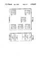
- FIG. 1is a block diagram of a typical Token ring network architecture
- FIG. 2is a block diagram of a representative station of a Token ring network
- FIG. 3is an illustration of the format of a Token packet that can circulate on the Token ring network of FIG. 1;
- FIG. 4is an illustration of the format of a data packet that can circulate on the Token ring network of FIG. 1;
- FIG. 5is an illustrative block diagram showing details of the RAM Buffer Controller of the station of FIG. 2;
- FIG. 6is an illustrative block diagram showing details of the Data Path Controller of the station of FIG. 2;
- FIG. 7is an illustrative drawing depicting the organization of data in the Receive Area of the buffer memory of the station of FIG. 2;
- FIG. 8is an illustrative drawing depicting the organization of data in the Transmit Area of the buffer memory of the station of FIG. 2;
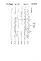
- FIG. 9is an illustrative timing diagram for the Receive protocol handshake between the MAC and the DPC of the station of FIG. 2;
- FIG. 10is an illustrative timing diagram for the Transmit protocol handshake between the MAC and the DPC of the station of FIG. 2;
- FIG. 11is an illustrative timing diagram for the transmit handshake protocol of FIG. 10 for the transmission of multiple linked chains of packets.
- the present inventioncomprises a novel method for monitoring and controlling transfers of data within individual stations of a Token ring network.
- the following descriptionis presented to enable any person skilled in the art to make and use the invention, and is provided in the context of a particular application and its requirements. Various modifications to the preferred embodiment will be readily apparent to those skilled in art, and the generic principles defined herein may be applied to other embodiments and applications without departing from the spirit and scope of the invention. Thus, the present invention is not intended to be limited to the embodiment shown, but is to be accorded the widest scope consistent with the principles and features disclosed herein.
- FIG. 2there is shown a block diagram illustrating a representative station 20 of a Token ring network which can use the method of the present invention.
- the station 20includes a Host processor 22 which, for example, can be a mainframe, work-station, minicomputer, or computer peripheral (such as a disk drive or a printer).
- the Host 22is interfaced to the transmission medium 24 of a Token ring network.
- the medium 24comprises a fiber optic medium which interconnects multiple stations in a Token ring network.
- the Host 22interfaces with the medium 24 through a data interface 26 which meets the ANSI X3T9.5 Fiber Distributed Data Interface (FDDI) Standard. It will be appreciated that the principles of the invention can apply to other data interfaces as well.
- FDDIFiber Distributed Data Interface
- the data interface 26includes a fiber optic transceiver (FOX) 28 which performs conversions between optical and electrical signals.
- the FOX 28serially receives optical bits from the transmission medium 24, and it serially transmits optical bits to the medium 24.
- the FOX 26converts optical bits received from the medium 24 to electrical bits for internal use by the station 20, and it converts electrical bits provided internally by the station 20 into optical bits for transmission onto the medium.
- An Encoder/Decoder ENDEC 30transfers data between the FOX 28 and a Media Access Controller (MAC) 32.
- the ENDEC 30can convert a serial bit stream received from the medium 24 by the FOX 28 into an 8-bit parallel stream which is transferred to the MAC 32.
- the ENDEC 30can convert an 8-bit parallel stream received from the MAC 32 into a serial bit stream for transfer to the FOX 28.
- the MAC 32performs functions which relate to the protocol involved in the transfer of packets between the station 20 and the transmission medium 24. For example, the MAC 32 determines when the station 20 can transmit onto the medium 24 and when it must receive from the medium 24. It also implements the logic required for Token handling and for the recognition of addresses in packets transmitted on the medium.
- the MAC 32When the station 20 transmits packets to the medium 24, the MAC 32 receives 8-bit bytes on Y-bus 34 from a Data Path Controller (DPC) 36 and provides 8-bit bytes to the ENDEC 30. Conversely, when the station 20 receives packets from the medium 24, the MAC 32 receives 8-bit bytes from the ENDEC 30, and transfers 8-bit bytes to the DPC 36 via Y-bus 34.
- DPCData Path Controller
- FIG. 3illustrates a format for Token transmission.
- FIG. 4illustrates a format for data packet transmission.
- the basic unit of information transmitted on the medium 24is a symbol.
- Data packetsare separated from each other by a prescribed number of Preamble (PA) symbols.
- the data (DATA) in the packetsis preceded by a start delimiter (SD) which establishes byte synchronization.
- SDstart delimiter
- FCframe control field
- DAdestination address
- SAsource address
- FCSframe check sequence
- Tterminator symbol
- Eerror
- Aaddress
- Ccopied
- Each of these threeis either in a Set or a Reset state.
- the E, A and C indicatorsare used by a destination station to provide information to a source station about the success of the packet reception.
- Erroris Set in case of a detected data corruption error.
- the address indicatoris Set to indicate that the destination station recognized the address as valid.
- the copied indicatoris Set to indicate the successful storage of the data (DATA) in buffer memory of the destination station.
- the MAC 32Upon receiving a data packet, the MAC 32 strips away all preamble and start delimiters, and transfers the data (DATA)in the data packet to the DPC 36 which, in turn, transfers the data to buffer memory 38 for storage. Similarly, the MAC 32 strips away all postamble and end-of-packet of delimiters. The MAC 32 checks incoming data packets for destination address and notifies the DPC 36 if an address mismatch is detected. The DPC causes stored data to be discarded or "flushed" from buffer memory 38, as explained below, upon detection by the MAC 32 of an address mismatch.
- the MAC 32also generates and checks CRC on the received data packets. Furthermore, it generates status bits which identify station conditions and packet status, such as the E, A and C bits which are transferred to the DPC 36. The packet status information is provided by the MAC 32 for storage in buffer memory 38. The MAC 32 and the DPC 36 coordinate transfers of data between the MAC 32 to the DPC 36 on Y-bus through the use of a novel handshake protocols described more fully below.
- Access to the medium 24is controlled by a rotating Token that determines which station has the right to transmit data packets on the medium 24 at any given time.
- the MAC 32transfers data packets received from the medium to the DPC 36 for storage in buffer memory provided, of course, that the packets are addressed to that station 20.
- the MAC 32also repeats data packets received from the medium 24, and it refrains from transmitting new packets onto the medium until it captures the Token.
- the MAC 32either repeats the Token on the medium 24 or holds it.
- the MAC 32can hold the Token for only a prescribed period of time. During that time it can transmit data packets onto the medium 24.
- the precise nature of the MAC 32depends upon the nature of the Token ring network in which it is employed. In essence, the MAC determines when the station 20 can transmit onto the medium 24, and it controls the interaction between the station 20 and the medium 24.
- the DPC 36converts data (DATA) received from the medium 24 from 8-bit bytes to 32-bit (long word) format. Conversely, it converts data (DATA) to be transmitted to the medium 24 from the 32-bit long word format in which it is stored in buffer memory 38 to the 8-bit byte format.
- the MAC 32When the station 20 is receiving a data packet from the medium 24, the MAC 32 provides 8-bit bytes of data on Y-bus 34.
- the DPC 36converts the 8-bit bytes into 32-bit long words, and provides the long words to D-bus 40 for storage in buffer memory 38.
- the DPC 36converts 32-bit long words transferred from the buffer memory 38 via D-bus 40 into 8-bit bytes for provision to the MAC 32.
- the DPC 36During receptions from the medium 24, the DPC 36 communicates with the MAC 32 through a novel handshake which facilitates the efficient storage of data in the buffer memory 38. Similarly, during transmissions to the medium 24, the DPC 36 communicates with the MAC 32 through a novel handshake which permits the MAC 32 to ascertain the appropriate time for terminating a transmission in the event that termination is required.
- a RAM buffer controller (RBC) 42generates addresses to the (RAM) buffer memory 38 for storage of packets which have been received from the medium 24 and for retrieval of packets which are to be transmitted to the medium 24.
- the illustrative drawings of FIG. 5show details of the RBC 42. It includes three direct memory access (DMA) channels for handling requests from the Host 22, the DPC 36 and a Node Processor (NP) 44.
- the RBC 42also includes a memory arbitrator 46 for arbitrating requests for access to the buffer memory 38. It will be appreciated that the drawings of FIG. 5 are merely illustrative and are provided to show that the buffer memory 38 can be addressed by three different entities.
- the buffer memoryis capable of inputting and outputting 32-bit data words at a rate of 200 megabits per second.
- the transfer rate on respective buses 34, 40 and 48(discussed below), however, is only 100 megabits per second.
- the Host 22 and NP 44take advantage of this speed differential by using "cycle stealing" to gain fast access to the memory 38. In the course of the storage or retrieval of data to or from the memory 38 by the DPC 36, the Host 22 or NP 44 can access the memory 38 by "stealing" cycles.
- the MAC 32, DPC 36 and RBC 42cooperate in data transfers from the medium 24 to the memory 38 so as to enable the buffer memory 38 to behave like a wrap-around FIFO.
- the MAC 32, DPC 36 and RBC 42also take advantage of a linked chain structure in which packets are stored for transmission onto the medium 24 to notify the MAC 32 each time a complete packet of data has been transmitted.
- the NP 44controls the overall operation of the data interface 26.
- the NP 44communicates with the other constituents of the data interface 26 using NP-bus 48.
- the main function of the NP 44is to initialize the devices comprising of the data interface 26, and to respond to various system level and packet level interrupts.
- the NP 44is assumed to have complete control over and knowledge of the states of the RBC 42 , DPC 36, MAC 32 and buffer memory 38. Each of these devices make its status available to the NP to enable it to maintain control.
- the 32-bit D-bus 40(not including four bits for parity), in addition to providing a data path between the DPC 36 and the buffer memory 38, provides a data path between the buffer memory 38 and the Host 22 and between the buffer memory 38 and the NP 44. As shown in FIG. 2, respective interface logic units 50 and 52 interface the D-bus 40 to the Host 22 and to the NP 44.
- the illustrative block diagram of FIG. 6shows further details of the DPC 32. It includes an internal FIFO 60 that performs the conversion between 8-bit bytes and 32-bit long words.
- the Y-bus 34 and the D-bus 40are coupled to the internal FIFO 60.
- Respective receiver and transmitter state machines 64 and 66 and FIFO control 68control the reception and transmission of data through the DPC 36.
- the state machines 64 and 66also control DPC interaction during RBC handshake protocols and MAC handshake protocols.
- RBC handshake logic 72completes sequential handshake protocols between the DPC 36 and RBC 42.
- MAC handshake logic 76completes handshake protocols between the MAC 32 and the DPC 36.
- a length counter 70counts the number of 8-bit bytes transferred through the DPC 36 during transmits and receives.
- the length counter 70is coupled to the D-bus 40 to facilitate storage of length as status information during receptions from the media 24 and to notify the RBC 42 as to the address of a next packet in a linked chain of packets during transmits to the media 24.
- the buffer memory 38is separated into two distinct areas.
- a Receive Areastores data packets which have been received from the medium 24.
- a Transmit Areastores data packets which are to be transmitted to the medium 24.
- FIG. 7there is shown a representation of the organization of data in the Receive Area of the buffer memory 38.
- the dataare conveniently organized as a FIFO. It will be appreciated that data packets extracted from the Receive Area typically are used by the Host 22 or the NP 44.
- data packetsare stored contiguously with each other, and within each data packet, long words of data are stored contiguously with each other.
- Each data packetbegins with a corresponding 32-bit long word which provides status information.
- the status informationincludes the length of the corresponding packet in terms of the number of 8-bit bytes contained in the packet.
- the present inventionprovides a novel method for receiving data packets from the medium 24 and for storing the data packets in the buffer memory 38 such that the stored data in the Receive Area are organized as a FIFO.
- FIG. 8show the organization of data stored in the Transmit Area of the buffer memory 38.
- Data packetsare stored in the Transmit Area as a linked chain of packets. Each respective packet begins with a long word that provides status information about the packet including the length of the packet. The data follow the status information. For each packet a pointer follows the data. The pointer points to the address in the Transmit Area of the next packet in the chain to be transmitted.
- Packetsare stored in the Transmit Area under control of the Host 22 or the NP 44. Storage in a linked chained facilitates efficient usage of limited memory space in the buffer memory 38. More particularly, under certain conditions, it is necessary to repeatedly transmit certain packet(s).
- the organization of data in linked chainspermits the storage of packets which must be transmitted repeatedly in a loop structure form.
- the FDDI Standardspecifies that when the network is initialized, each station in the ring must "bid” for priority. Each station presents its "bid” by repeatedly transmitting to the medium 24 its own claim packet. This claim packet is compared in a manner specified in the FDDI Standard with claim packets from other stations in order to establish a hierarchy of priority for access to the medium 24.
- the protocol handshake between the MAC 32 and the DPC 36facilitates the storage of received data packets in the buffer memory 38 such that data in the Receive Area is organized as a FIFO. That is, through the protocol, the status information corresponding to a received packet including the length of the received packet is stored in buffer memory 38 contiguously with the data of the packet at the beginning of the packet. Storage of the status information at the beginning of the packet is significant since the data of the packet are stored serially within the buffer memory in the sequence in which they are received, and since the status information is transferred from the MAC 32 after the data corresponding to that status information already have been stored in the memory 38.
- the protocol handshake between the MAC 32 and the DPC 36facilitates the identification of the status information so that the RBC 42 can cause that information to be stored at the beginning of data which have already been sequentially stored in memory 38 in the order in which they were received.
- the illustrative timing diagram of FIG. 9,shows details of the protocol handshake between the MAC 32 and the DPC 36 used during the reception of data.
- the MAC 32detects a received packet on the media 24, it transitions signal RECEIVE from lo to hi.
- the MAC 32transitions signal DAVALID (Data Valid) from lo to hi.
- the DPC 36detects these transitions, and in response, one clock cycle after they are both hi, it transitions signal BRCVPKT (Begin Receive Packet) from lo to hi, where it remains for only one clock cycle.
- the DPC 36provides BRCVPKT so as to notify the RBC 42 of the fact that a hi state DWRREQ (DPC Write Request) which will soon follow will be a request to store a first long word of a received packet.
- the DPC 36provides to the RBC 42 hi state signal DISNHRQ which requests the RBC 42 to disable the NP 44 and the Host 22 from accessing the buffer memory 38.
- the RBC 42calculates the start address for storage of received data packets.
- the Host 22 and NP 44are disabled from accessing the buffer memory 38 while the RBC 42 calculates the start address because otherwise their accessing of the memory might interfere with the timely calculation of the start address.
- the MAC 32 and therefore, the buffer memory 38must be prepared to receive packets immediately when the MAC 32 receives them.
- DISNHRQtransitions from hi to lo, and the Host 22 and the NP 44 can once again access the memory 38.
- Signal DWRREQis provided by the DPC to the RBC to request it to address a memory location for storage of a 32-bit long word to be transferred from the internal FIFO 60 of the DPC to buffer memory 38.
- Signal DWRREQpersists until the RBC 42 acknowledges to the DPC, through signal DWRACK, that the DPC 36 can transfer to the RBC the long word.
- Datais transferred from the internal FIFO 60 of the DPC 36 to the buffer memory 38 via D-bus 40.
- the sequence of DWRREQ and DWRACK signalscontinues until an entire packet of data has been transferred.
- the MAC 32When the MAC 32 is about to transfer the status information which it has generated, it transitions signal RECEIVE from hi to lo, and it transitions signal DAVALID from hi to lo for one clock cycle, and then it transitions DAVALID back from lo to hi for another clock cycle. RECEIVE stays low during the transition of DAVALID back to hi. It then transfers to the DPC 36 the status information. The transition of DAVALID just described informs the DPC 36 that the MAC 32 has completed the reception of an entire data packet, and that what follows is status information corresponding to that packet.
- the DPC 36In response to this transition of DAVALID, the DPC 36 causes signal DISNHRQ to once again transition from lo to hi. Consequently, access to the buffer memory 38 by the Host 22 and the NP 44 is disabled.
- the DPC 36also transitions signal ERCVPKT (End of Received Packet) from lo to hi to inform the RBC 42 that the long word that will be transferred is status information for the packet.
- ERCVPKTEnd of Received Packet
- the RBCmoves its internal pointer to before the start location in memory of the data in the packet, so that the status information can be stored contiguously with that packet and at the beginning of it.
- the DPC 36then provides to the RBC 42 the status information including the calculated length of the packet.
- the length of the packetis calculated by the DPC 36 through its length counter 70 in the course of the transfer of data in the packet by counting the number of 8-bit bytes transferred to the memory 38 for storage.
- the RBC 42moves its pointer to the end of the packet and awaits transfer of the next data packet to buffer memory 38.
- the MAC 32can cause data to be stored in buffer memory 38 before the MAC determines that the destination of the received data are actually another station. In that case, upon determining that the data are destined for elsewhere, the MAC 32 causes the DPC 36 to instruct the RBC 42 to "flush" the data. To accomplish such a flushing, the RBC 42 moves its internal pointer back to the start of the data to be flushed. Thus, a next received packet of data will be stored on top the "flushed" data packet.
- the Transmit protocol handshake between the MAC 32 and the DPC 36is illustrated in FIG. 10. It advantageously permits the transmission of packets of data on a packet-by- packet basis which can easily be interrupted between packets in the event that packet transmission must be terminated. Packet transmission, for example, may have to be terminated because of expiration of the Token-holding timer. Another reason the MAC 32 needs to know the end of the packet is so that it knows when to add postamble information to the transmitted packet.
- the DPCtransitions signal MEDREQS (Media Request-Synchronous) from lo to hi in order to provide a media request for a transmission to the media 24 of a synchronous packet.
- Signal MEDREQSremains in a hi state until all synchronous data packets to be transferred have been transmitted to the media 24. Thus, even if transmission is interrupted for some reason, signal MEDREQS remains hi until transmission of all packets is complete.
- the MAC 32Upon capturing from the medium 24 a Token, the MAC 32 transitions signal XMEDAVS from lo to hi. Signal XMEDAVS indicates to the DPC 36 that the media 24 now is available to for the transmission of packets.
- the DPC 36transitions signal DRDREQS (DPC Read Request-Synchronous) to a hi state in order to request permission from the RBC 42 to read a data packet from the buffer memory 38.
- the RBC 42transitions signal DRDACKS to a hi state to acknowledge the read request.
- the buffer memory 38then transfers the first long word containing digital status information from the buffer memory 38 to the DPC.
- the DPC 36extracts the length of the packet from the first long word of the packet which comprises the status information for the packet.
- the DPC 36then proceeds to receive from the buffer memory 38 the packet data.
- the DPC 36stores each 32-bit long word transferred from memory 38 in its internal FIFO 60. It transfers the stored long word from its internal FIFO 60 to the MAC 32 one 8-bit byte at a time.
- the internal FIFO 60can store two long words at a time. As one long word is received by the internal FIFO 60 from the buffer memory 38, a previously received long word is transferred from the internal FIFO 60 to Y-bus 34 for transfer to the MAC 32.
- the DPC 36transitions signal RDYBYT from lo to hi.
- the DPC 36after transitioning signal RDYBYT from lo to hi, actually begins transferring a packet to the MAC 32 after the MAC 32 transitions signal XFRBYT (Transfer Byte) from lo to hi.
- XFRBYTTransfer Byte
- RDYBYTtransitions from hi to lo.
- the DPC 36knows when to transition signal RDYBYT from hi to lo based upon the length of the packet which was extracted from the status information at the beginning of the packet.
- the DPC 36through its counter 70, counts the number of 8-bit bytes transferred through it to the MAC 32. When the number of transferred bytes equals the length of the packet indicated in the packet's status information, it transitions signal RDYBYT from hi to lo.
- the transitioning of signal RDYBYT from hi to loinforms the MAC 32 that an entire packet has been transferred.
- the FDDI Standardrequires that transmission of packets be interruptable, but it also requires that a transmission not be interrupted until an entire packet has been transferred.
- the transition of RDYBYT from hi to lo after each packetinforms the MAC 32 as to when an interruption of a transmission can occur in accordance with the FDDI Standard.
- the MAC 32After the transmission of an individual packet, and the transitioning of signal RDYBYT from hi to lo, the MAC 32 causes signals XMEDAVS and XFRBYT, to transition from hi to lo. Subsequently, in the event that the MAC 32 is ready to receive another packet, it causes signal XMEDAVS to transition once again from lo to hi. In response, the DPC 36 initiates the exchange of signals DRDREQS and DRDACKS with the RBC 42. Upon receiving ample data in its internal FIFO 60, the DPC causes signal RDYBYT to once again transition from lo to hi. In response, the MAC 32 transitions XFRBYT from lo to hi, and another complete data packet is transferred.
- the MAC 32can cause another linked chain of packets to be transferred. Alternately, it can pass the Token to another station.
- FIG. 11provides a timing diagram showing a sequence of signals used in the protocol handshake between the MAC 32 and the DPC 36 to transmit from buffer memory 38 to the medium 24 multiple packets of data in which some packets are synchronous and others asynchronous.
- the FDDI Standarddistinguishes between synchronous and asynchronous packets. The Standard ordinarily requires that synchronous packets be transmitted before asynchronous packets.
- the DPC 36first transitions signal MEDREQA (Media Request Asynchronous) to a hi state.
- the MAC 32transitions XMEDAVA to a hi state.
- the DPC 36 and the RBC 42exchange DRDREQA and DRDACKA signals.
- signal RDYBYTtransitions from lo to hi to indicate that asynchronous data are stored in internal FIFO 60 of the DPC 36 and are ready for transfer to the MAC 32.
- the MAC 32responds by transitioning signal XFRBYT from lo to hi so as to cause a transfer of a packet of asynchronous data.
- the DPC 36transitions to the signal MEDREQS to a hi state.
- a transfer of synchronous datahas been requested.
- synchronous transmissionstake precedence over asynchronous transitions. Consequently, after the transfer of one complete packet of the chain of asynchronous data, the MAC 32 transitions signal XMEDAVA from hi to lo, and transitions signal XMEDAVS from lo to hi.
- the data available in the DPC 36is synchronous data. Consequently, upon the next transition from lo to hi of signal XFRBYT, synchronous data is transferred from the internal FIFO 60 of the DPC 36 to the MAC 32.
- the transfer of synchronous datacontinues until each and every packet of synchronous data has been transmitted from the DPC 36 to the MAC 32.
- the transfer of the chain (CS1) of synchronous packetsis completed at arrow 1.
- the transmission of the first chain (CA1) of asynchronous packetscontinues with the transmission of the second packet in that chain. Transmission continues until the completion of the first chain (CA1) of asynchronous packets which is indicated by arrow 2.
- the DPCIn the course of transferring the packet from the DPC 36 to the MAC 32, the DPC counts the number of bytes transferred. When the last byte occurs, the DPC 36 knows that that byte is the pointer to the start address of the next packet in the chain. The DPC 36 indicates to the RBC 42 via hi state signals DRDREQS and LDRPXS that the address of the next packet is present on the D-bus 40. The RBC 42 stores that address and will use it for the next hi signal DRDREQS (i.e. for the next packet). (For asynchronous packets, signals DRDEQA and LDRPXA are used).
Landscapes
- Engineering & Computer Science (AREA)
- Computer Networks & Wireless Communication (AREA)
- Signal Processing (AREA)
- Small-Scale Networks (AREA)
Abstract
Description
Claims (12)
Priority Applications (5)
| Application Number | Priority Date | Filing Date | Title |
|---|---|---|---|
| US07/226,610US4914652A (en) | 1988-08-01 | 1988-08-01 | Method for transfer of data between a media access controller and buffer memory in a token ring network |
| EP89307532AEP0353927B1 (en) | 1988-08-01 | 1989-07-25 | Method for transfer of data between a media access controller and buffer memory in a token ring network |
| AT89307532TATE143203T1 (en) | 1988-08-01 | 1989-07-25 | METHOD FOR DATA TRANSMISSION BETWEEN A MEDIA ACCESS CONTROLLER AND A BUFFER MEMORY IN A TOKENRING NETWORK |
| DE68927214TDE68927214T2 (en) | 1988-08-01 | 1989-07-25 | Method for data transmission between a media access controller and a buffer memory in a token ring network |
| JP1200179AJPH02100439A (en) | 1988-08-01 | 1989-07-31 | Method for using in token ring network |
Applications Claiming Priority (1)
| Application Number | Priority Date | Filing Date | Title |
|---|---|---|---|
| US07/226,610US4914652A (en) | 1988-08-01 | 1988-08-01 | Method for transfer of data between a media access controller and buffer memory in a token ring network |
Publications (1)
| Publication Number | Publication Date |
|---|---|
| US4914652Atrue US4914652A (en) | 1990-04-03 |
Family
ID=22849626
Family Applications (1)
| Application Number | Title | Priority Date | Filing Date |
|---|---|---|---|
| US07/226,610Expired - LifetimeUS4914652A (en) | 1988-08-01 | 1988-08-01 | Method for transfer of data between a media access controller and buffer memory in a token ring network |
Country Status (5)
| Country | Link |
|---|---|
| US (1) | US4914652A (en) |
| EP (1) | EP0353927B1 (en) |
| JP (1) | JPH02100439A (en) |
| AT (1) | ATE143203T1 (en) |
| DE (1) | DE68927214T2 (en) |
Cited By (34)
| Publication number | Priority date | Publication date | Assignee | Title |
|---|---|---|---|---|
| US5043981A (en)* | 1990-05-29 | 1991-08-27 | Advanced Micro Devices, Inc. | Method of and system for transferring multiple priority queues into multiple logical FIFOs using a single physical FIFO |
| US5046182A (en)* | 1989-12-01 | 1991-09-03 | National Semiconductor Corporation | Code points for transferring data from a network transmission medium to a station on the network |
| US5051985A (en)* | 1988-10-28 | 1991-09-24 | International Business Machines Corporation | Contention resolution in a communications ring |
| US5065397A (en)* | 1989-08-14 | 1991-11-12 | Kabushiki Kaisha Toshiba | Data synchronous transfer system using a fiber distributed data exchange interface |
| WO1991017609A1 (en)* | 1990-05-08 | 1991-11-14 | Caterpillar Inc. | Fault tolerant serial communications network |
| US5068849A (en)* | 1989-03-09 | 1991-11-26 | Mitsubishi Denki Kabushiki Kaisha | Cyclic data transmission method |
| US5159592A (en)* | 1990-10-29 | 1992-10-27 | International Business Machines Corporation | Network address management for a wired network supporting wireless communication to a plurality of mobile users |
| US5187709A (en)* | 1990-05-08 | 1993-02-16 | Caterpillar Inc. | Fault tolerant serial communications network |
| US5210749A (en)* | 1990-05-29 | 1993-05-11 | Advanced Micro Devices, Inc. | Configuration of srams as logical fifos for transmit and receive of packet data |
| US5241540A (en)* | 1991-07-31 | 1993-08-31 | International Business Machines Corporation | Reverse ordered control information transmission |
| US5247626A (en)* | 1990-05-29 | 1993-09-21 | Advanced Micro Devices, Inc. | Fddi controller having flexible buffer management |
| JPH0677954A (en)* | 1990-06-29 | 1994-03-18 | Digital Equip Corp <Dec> | Apparatus and method for processing of code provided with arbitrary selective status encoding |
| US5305321A (en)* | 1992-02-24 | 1994-04-19 | Advanced Micro Devices | Ethernet media access controller with external address detection interface and associated method |
| US5351242A (en)* | 1992-04-14 | 1994-09-27 | Marian Kramarczyk | Method and apparatus for configuring and maintaining token ring networks |
| US5394390A (en)* | 1993-10-29 | 1995-02-28 | International Business Machines Corporation | FDDI network test adapter history store circuit (HSC) |
| US5434976A (en)* | 1992-09-28 | 1995-07-18 | Standard Microsystems Corporation | Communications controller utilizing an external buffer memory with plural channels between a host and network interface operating independently for transferring packets between protocol layers |
| US5442633A (en)* | 1992-07-08 | 1995-08-15 | International Business Machines Corporation | Shortcut network layer routing for mobile hosts |
| US5450564A (en)* | 1990-05-04 | 1995-09-12 | Unisys Corporation | Method and apparatus for cache memory access with separate fetch and store queues |
| US5481676A (en)* | 1993-07-09 | 1996-01-02 | Siemens Aktiengesellschaft | Arrangement for the decentralized control of access to a bus by units connected to the bus |
| US5519701A (en)* | 1995-03-29 | 1996-05-21 | International Business Machines Corporation | Architecture for high performance management of multiple circular FIFO storage means |
| US5539727A (en)* | 1992-04-14 | 1996-07-23 | Kramarczyk; Marian | Method and apparatus for configuring and maintaining token ring networks |
| US5546539A (en)* | 1993-12-29 | 1996-08-13 | Intel Corporation | Method and system for updating files of a plurality of storage devices through propogation of files over a nework |
| US5555380A (en)* | 1991-04-11 | 1996-09-10 | Nec Corporation | Data transfer system with buffer request including block length to update the buffer pointer prior to transferring of the block |
| US5687316A (en)* | 1994-07-29 | 1997-11-11 | International Business Machines Corporation | Communication apparatus and methods having P-MAC, I-MAC engines and buffer bypass for simultaneously transmitting multimedia and packet data |
| US5819113A (en)* | 1996-06-06 | 1998-10-06 | Advanced Micro Devices, Inc. | Method of identifying end of pocket by writing the address of last data into the first location of the memory |
| US5842003A (en)* | 1997-03-26 | 1998-11-24 | Unisys Corporation | Auxiliary message arbitrator for digital message transfer system in network of hardware modules |
| US5873089A (en)* | 1995-09-04 | 1999-02-16 | Hewlett-Packard Company | Data handling system with circular queue formed in paged memory |
| US5875442A (en)* | 1992-08-03 | 1999-02-23 | International Business Machines Corporation | Method and apparatus for enhancing access to a remote database employing dynamic buffer management |
| US6061767A (en)* | 1997-12-18 | 2000-05-09 | Advanced Micro Devices, Inc. | Apparatus and method in a network interface device for storing status information contiguous with a corresponding data frame in a buffer memory |
| US6304553B1 (en) | 1998-09-18 | 2001-10-16 | Lsi Logic Corporation | Method and apparatus for processing data packets |
| US6373841B1 (en)* | 1998-06-22 | 2002-04-16 | Agilent Technologies, Inc. | Integrated LAN controller and web server chip |
| US20020097731A1 (en)* | 2001-01-25 | 2002-07-25 | Ljubisa Tancevski | Distributed intelligence MAC protocols for DWDM ring networks |
| US6622198B2 (en)* | 2000-08-31 | 2003-09-16 | United Memories, Inc. | Look-ahead, wrap-around first-in, first-out integrated (FIFO) circuit device architecture |
| US20040151126A1 (en)* | 2002-11-29 | 2004-08-05 | Kabushiki Kaisha Toshiba | Communication system, communication control method and communication control method |
Families Citing this family (6)
| Publication number | Priority date | Publication date | Assignee | Title |
|---|---|---|---|---|
| DE3742748A1 (en)* | 1987-12-17 | 1989-07-06 | Philips Patentverwaltung | COUPLING AND COUPLING CONTROL FOR A SWITCHING NODE OF A BROADBAND SWITCHING SYSTEM |
| JPH03135133A (en)* | 1989-10-20 | 1991-06-10 | Toshiba Corp | Multimedia integrated network system |
| JP3085311B2 (en)* | 1990-05-25 | 2000-09-04 | 日本電信電話株式会社 | FIFO buffer |
| EP0459756A3 (en)* | 1990-05-29 | 1994-06-15 | Advanced Micro Devices Inc | Fiber distributed data interface network |
| US5153884A (en)* | 1990-08-15 | 1992-10-06 | Allen-Bradley Company, Inc. | Intelligent network interface circuit |
| US8060668B2 (en) | 2004-09-08 | 2011-11-15 | Fisher-Rosemount Systems, Inc. | Low latency data packet reception and processing |
Citations (1)
| Publication number | Priority date | Publication date | Assignee | Title |
|---|---|---|---|---|
| US4652874A (en)* | 1984-12-24 | 1987-03-24 | Motorola, Inc. | Serial communication interface for a local network controller |
Family Cites Families (1)
| Publication number | Priority date | Publication date | Assignee | Title |
|---|---|---|---|---|
| US4942515A (en)* | 1986-03-31 | 1990-07-17 | Wang Laboratories, Inc. | Serial communications controller with FIFO register for storing supplemental data and counter for counting number of words within each transferred frame |
- 1988
- 1988-08-01USUS07/226,610patent/US4914652A/ennot_activeExpired - Lifetime
- 1989
- 1989-07-25DEDE68927214Tpatent/DE68927214T2/ennot_activeExpired - Fee Related
- 1989-07-25ATAT89307532Tpatent/ATE143203T1/ennot_activeIP Right Cessation
- 1989-07-25EPEP89307532Apatent/EP0353927B1/ennot_activeExpired - Lifetime
- 1989-07-31JPJP1200179Apatent/JPH02100439A/enactivePending
Patent Citations (1)
| Publication number | Priority date | Publication date | Assignee | Title |
|---|---|---|---|---|
| US4652874A (en)* | 1984-12-24 | 1987-03-24 | Motorola, Inc. | Serial communication interface for a local network controller |
Cited By (37)
| Publication number | Priority date | Publication date | Assignee | Title |
|---|---|---|---|---|
| US5051985A (en)* | 1988-10-28 | 1991-09-24 | International Business Machines Corporation | Contention resolution in a communications ring |
| US5068849A (en)* | 1989-03-09 | 1991-11-26 | Mitsubishi Denki Kabushiki Kaisha | Cyclic data transmission method |
| US5065397A (en)* | 1989-08-14 | 1991-11-12 | Kabushiki Kaisha Toshiba | Data synchronous transfer system using a fiber distributed data exchange interface |
| US5046182A (en)* | 1989-12-01 | 1991-09-03 | National Semiconductor Corporation | Code points for transferring data from a network transmission medium to a station on the network |
| US5450564A (en)* | 1990-05-04 | 1995-09-12 | Unisys Corporation | Method and apparatus for cache memory access with separate fetch and store queues |
| US5187709A (en)* | 1990-05-08 | 1993-02-16 | Caterpillar Inc. | Fault tolerant serial communications network |
| WO1991017609A1 (en)* | 1990-05-08 | 1991-11-14 | Caterpillar Inc. | Fault tolerant serial communications network |
| US5247626A (en)* | 1990-05-29 | 1993-09-21 | Advanced Micro Devices, Inc. | Fddi controller having flexible buffer management |
| US5210749A (en)* | 1990-05-29 | 1993-05-11 | Advanced Micro Devices, Inc. | Configuration of srams as logical fifos for transmit and receive of packet data |
| US5043981A (en)* | 1990-05-29 | 1991-08-27 | Advanced Micro Devices, Inc. | Method of and system for transferring multiple priority queues into multiple logical FIFOs using a single physical FIFO |
| JPH0677954A (en)* | 1990-06-29 | 1994-03-18 | Digital Equip Corp <Dec> | Apparatus and method for processing of code provided with arbitrary selective status encoding |
| US5159592A (en)* | 1990-10-29 | 1992-10-27 | International Business Machines Corporation | Network address management for a wired network supporting wireless communication to a plurality of mobile users |
| US5555380A (en)* | 1991-04-11 | 1996-09-10 | Nec Corporation | Data transfer system with buffer request including block length to update the buffer pointer prior to transferring of the block |
| US5241540A (en)* | 1991-07-31 | 1993-08-31 | International Business Machines Corporation | Reverse ordered control information transmission |
| US5305321A (en)* | 1992-02-24 | 1994-04-19 | Advanced Micro Devices | Ethernet media access controller with external address detection interface and associated method |
| US5539727A (en)* | 1992-04-14 | 1996-07-23 | Kramarczyk; Marian | Method and apparatus for configuring and maintaining token ring networks |
| US5351242A (en)* | 1992-04-14 | 1994-09-27 | Marian Kramarczyk | Method and apparatus for configuring and maintaining token ring networks |
| US5442633A (en)* | 1992-07-08 | 1995-08-15 | International Business Machines Corporation | Shortcut network layer routing for mobile hosts |
| US5875442A (en)* | 1992-08-03 | 1999-02-23 | International Business Machines Corporation | Method and apparatus for enhancing access to a remote database employing dynamic buffer management |
| US5434976A (en)* | 1992-09-28 | 1995-07-18 | Standard Microsystems Corporation | Communications controller utilizing an external buffer memory with plural channels between a host and network interface operating independently for transferring packets between protocol layers |
| US5481676A (en)* | 1993-07-09 | 1996-01-02 | Siemens Aktiengesellschaft | Arrangement for the decentralized control of access to a bus by units connected to the bus |
| US5394390A (en)* | 1993-10-29 | 1995-02-28 | International Business Machines Corporation | FDDI network test adapter history store circuit (HSC) |
| US5546539A (en)* | 1993-12-29 | 1996-08-13 | Intel Corporation | Method and system for updating files of a plurality of storage devices through propogation of files over a nework |
| US5758075A (en)* | 1994-07-29 | 1998-05-26 | International Business Machines Corporation | Multimedia communication apparatus and methods |
| US5708779A (en)* | 1994-07-29 | 1998-01-13 | International Business Machines Corporation | Multimedia system and method of controlling data transfer between a host system and a network adapter using a DMA engine |
| US5687316A (en)* | 1994-07-29 | 1997-11-11 | International Business Machines Corporation | Communication apparatus and methods having P-MAC, I-MAC engines and buffer bypass for simultaneously transmitting multimedia and packet data |
| US5519701A (en)* | 1995-03-29 | 1996-05-21 | International Business Machines Corporation | Architecture for high performance management of multiple circular FIFO storage means |
| US5873089A (en)* | 1995-09-04 | 1999-02-16 | Hewlett-Packard Company | Data handling system with circular queue formed in paged memory |
| US5819113A (en)* | 1996-06-06 | 1998-10-06 | Advanced Micro Devices, Inc. | Method of identifying end of pocket by writing the address of last data into the first location of the memory |
| US5842003A (en)* | 1997-03-26 | 1998-11-24 | Unisys Corporation | Auxiliary message arbitrator for digital message transfer system in network of hardware modules |
| US6061767A (en)* | 1997-12-18 | 2000-05-09 | Advanced Micro Devices, Inc. | Apparatus and method in a network interface device for storing status information contiguous with a corresponding data frame in a buffer memory |
| US6373841B1 (en)* | 1998-06-22 | 2002-04-16 | Agilent Technologies, Inc. | Integrated LAN controller and web server chip |
| US6304553B1 (en) | 1998-09-18 | 2001-10-16 | Lsi Logic Corporation | Method and apparatus for processing data packets |
| US6622198B2 (en)* | 2000-08-31 | 2003-09-16 | United Memories, Inc. | Look-ahead, wrap-around first-in, first-out integrated (FIFO) circuit device architecture |
| US20020097731A1 (en)* | 2001-01-25 | 2002-07-25 | Ljubisa Tancevski | Distributed intelligence MAC protocols for DWDM ring networks |
| US7899066B2 (en)* | 2001-01-25 | 2011-03-01 | Alcatel Lucent | Distributed intelligence MAC protocols for DWDM ring networks |
| US20040151126A1 (en)* | 2002-11-29 | 2004-08-05 | Kabushiki Kaisha Toshiba | Communication system, communication control method and communication control method |
Also Published As
| Publication number | Publication date |
|---|---|
| EP0353927A2 (en) | 1990-02-07 |
| ATE143203T1 (en) | 1996-10-15 |
| EP0353927B1 (en) | 1996-09-18 |
| JPH02100439A (en) | 1990-04-12 |
| EP0353927A3 (en) | 1992-05-27 |
| DE68927214D1 (en) | 1996-10-24 |
| DE68927214T2 (en) | 1997-03-27 |
Similar Documents
| Publication | Publication Date | Title |
|---|---|---|
| US4914652A (en) | Method for transfer of data between a media access controller and buffer memory in a token ring network | |
| EP0459757B1 (en) | Network adapter | |
| JP3452590B2 (en) | Network adapter for controlling flow of data arranged in packets from system memory to network and method of controlling data flow | |
| US5247626A (en) | Fddi controller having flexible buffer management | |
| US4493021A (en) | Multicomputer communication system | |
| US5136582A (en) | Memory management system and method for network controller | |
| US5764895A (en) | Method and apparatus for directing data packets in a local area network device having a plurality of ports interconnected by a high-speed communication bus | |
| US5857075A (en) | Method and integrated circuit for high-bandwidth network server interfacing to a local area network | |
| EP0076880B1 (en) | A local area contention network data communication system | |
| US4715030A (en) | Local area network bridge | |
| US5058109A (en) | Exclusionary network adapter apparatus and related method | |
| US5619651A (en) | I/O data unit symmetry in a media access control/host system interface unit | |
| US5721955A (en) | System for transferring portion of data to host from buffer if size of packet is greater than first threshold value but less than second threshold value | |
| US5463762A (en) | I/O subsystem with header and error detection code generation and checking | |
| US5553302A (en) | Serial I/O channel having independent and asynchronous facilities with sequence recognition, frame recognition, and frame receiving mechanism for receiving control and user defined data | |
| EP0130206B1 (en) | Method and apparatus for bus contention resolution | |
| US5748634A (en) | Method and apparatus for implementing a two-port ethernet bridge using a semaphoring technique | |
| US4593281A (en) | Local area network interframe delay controller | |
| US5119374A (en) | Method of and system for implementing multiple levels of asynchronous priority in FDDI networks | |
| US4612541A (en) | Data transmission system having high-speed transmission procedures | |
| EP0459756A2 (en) | Fiber distributed data interface network | |
| EP0597030B1 (en) | Automatically deactivated no-owner frame removal mechanism for token ring networks | |
| KR100367138B1 (en) | Network Interface Controller | |
| JP2601914B2 (en) | Data transmission equipment | |
| JP2001502855A (en) | End-of-packet detection for storing multiple packets in SRAM |
Legal Events
| Date | Code | Title | Description |
|---|---|---|---|
| AS | Assignment | Owner name:ADVANCED MICRO DEVICES, INC., 901 THOMPSON PLACE, Free format text:ASSIGNMENT OF ASSIGNORS INTEREST.;ASSIGNOR:NGUYEN, HANG DIEM;REEL/FRAME:004957/0155 Effective date:19880819 Owner name:ADVANCED MICRO DEVICES, INC., A CORP. OF DE,CALIFO Free format text:ASSIGNMENT OF ASSIGNORS INTEREST;ASSIGNOR:NGUYEN, HANG DIEM;REEL/FRAME:004957/0155 Effective date:19880819 | |
| STCF | Information on status: patent grant | Free format text:PATENTED CASE | |
| FEPP | Fee payment procedure | Free format text:PAYOR NUMBER ASSIGNED (ORIGINAL EVENT CODE: ASPN); ENTITY STATUS OF PATENT OWNER: LARGE ENTITY | |
| FPAY | Fee payment | Year of fee payment:4 | |
| FPAY | Fee payment | Year of fee payment:8 | |
| AS | Assignment | Owner name:MORGAN STANLEY & CO. INCORPORATED, NEW YORK Free format text:SECURITY INTEREST;ASSIGNOR:LEGERITY, INC.;REEL/FRAME:011601/0539 Effective date:20000804 | |
| AS | Assignment | Owner name:LEGERITY, INC., TEXAS Free format text:ASSIGNMENT OF ASSIGNORS INTEREST;ASSIGNOR:ADVANCED MICRO DEVICES, INC.;REEL/FRAME:011700/0686 Effective date:20000731 | |
| FPAY | Fee payment | Year of fee payment:12 | |
| AS | Assignment | Owner name:MORGAN STANLEY & CO. INCORPORATED, AS FACILITY COL Free format text:SECURITY AGREEMENT;ASSIGNORS:LEGERITY, INC.;LEGERITY HOLDINGS, INC.;LEGERITY INTERNATIONAL, INC.;REEL/FRAME:013372/0063 Effective date:20020930 | |
| AS | Assignment | Owner name:SAXON IP ASSETS LLC, TEXAS Free format text:ASSIGNMENT OF ASSIGNORS INTEREST;ASSIGNOR:LEGERITY, INC.;REEL/FRAME:017537/0307 Effective date:20060324 | |
| AS | Assignment | Owner name:LEGERITY INTERNATIONAL, INC., TEXAS Free format text:RELEASE OF SECURITY INTEREST;ASSIGNOR:MORGAN STANLEY SENIOR FUNDING INC., AS ADMINISTRATIVE AGENT, SUCCESSOR TO MORGAN STANLEY & CO. INCORPORATED, AS FACILITY COLLATERAL AGENT;REEL/FRAME:019699/0854 Effective date:20070727 Owner name:LEGERITY, INC., TEXAS Free format text:RELEASE OF SECURITY INTEREST;ASSIGNOR:MORGAN STANLEY SENIOR FUNDING INC., AS ADMINISTRATIVE AGENT, SUCCESSOR TO MORGAN STANLEY & CO. INCORPORATED;REEL/FRAME:019690/0647 Effective date:20070727 Owner name:LEGERITY, INC., TEXAS Free format text:RELEASE OF SECURITY INTEREST;ASSIGNOR:MORGAN STANLEY SENIOR FUNDING INC., AS ADMINISTRATIVE AGENT, SUCCESSOR TO MORGAN STANLEY & CO. INCORPORATED, AS FACILITY COLLATERAL AGENT;REEL/FRAME:019699/0854 Effective date:20070727 Owner name:LEGERITY HOLDINGS, INC., TEXAS Free format text:RELEASE OF SECURITY INTEREST;ASSIGNOR:MORGAN STANLEY SENIOR FUNDING INC., AS ADMINISTRATIVE AGENT, SUCCESSOR TO MORGAN STANLEY & CO. INCORPORATED, AS FACILITY COLLATERAL AGENT;REEL/FRAME:019699/0854 Effective date:20070727 | |
| AS | Assignment | Owner name:SAXON INNOVATIONS, LLC, TEXAS Free format text:ASSIGNMENT OF ASSIGNORS INTEREST;ASSIGNOR:SAXON IP ASSETS, LLC;REEL/FRAME:020279/0496 Effective date:20071016 | |
| AS | Assignment | Owner name:RPX CORPORATION,CALIFORNIA Free format text:ASSIGNMENT OF ASSIGNORS INTEREST;ASSIGNOR:SAXON INNOVATIONS, LLC;REEL/FRAME:024202/0302 Effective date:20100324 |